1
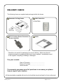
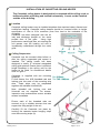
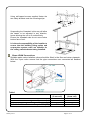
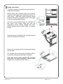
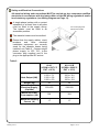
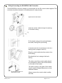
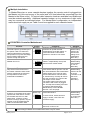
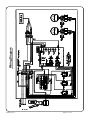
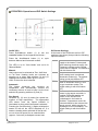
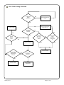
CASSETTAIR CEILING HEATER INSTALLATION, OPERATION & MAINTENANCE INSTRUCTIONS PLEASE READ THESE INSTRUCTIONS CAREFULLY BEFORE ATTEMPTING INSTALLATION Biddle Air Systems Ltd St. Mary’s Road Nuneaton Warwickshire England CV11 5AU Email: [email protected] Tel: +44 (0) 24 76 384233 Fax: +44 (0) 24 76 373621 www.biddle-air.co.uk January 2013 Page 1 of 15 DELIVERY CHECK The following items are supplied and packaged within the boxes. Cassettair Ceiling Heater Wall Controller ECONTROL Mounting Strips (x2) IEC C13 In-line Power Connector (screw terminal) Grille Check the unit and all its packaging for correct delivery. Make sure that all components and accompanying parts have been supplied. Immediately report to the supplier if anything is missing or damaged. For your records Date of Purchase…………………………….. Place of Purchase……………………………. Serial Number………………………………… For warranty purposes proof of purchase is necessary so please keep a copy of your invoice. (All documentation supplied with each unit should be stored and kept for future reference) January 2013 Page 2 of 15 INSTALLATION OF CASSETTAIR CEILING HEATER The Cassettair ceiling heater is designed to be recessed within ceiling voids or bulkheads within a building and located horizontally. It must not be installed outside of the building. Location Cassettair ceiling heaters may be installed anywhere that requires instant, discreet and trouble-free heating. Cassettair ceiling heaters should be mounted within its height specification of 1.8m to 3.5m maximum (from floor level to the underside of the unit/grille). Cassettair has been designed with the air inlet and discharge located on the same profiled face of the grille. Using high performance centrifugal fans, air entering the unit passes over the heating coil and is immediately redistributed through the outlet grille. Ceiling Suspension Cassettair can be mounted either before or after the ceiling suspended grid system is installed. The ceiling heater has been designed to easily fit universal suspended ceiling grid systems. Ensure there is sufficient height clearance in the ceiling void for the heater to be fitted, for dimensional details refer to Figure 1. Cassettair is supplied with two mounting strips (A). Fit and secure four M10 threaded rods and locking nuts into each of the mounting strip slots. These strips may be suspended together with suitable Unistrut® (B). Note: threaded rod, locking nuts and Unistrut® are not supplied. For access, inspection and maintenance ensure suitable access is available. Ensure each of the threaded rods are secured on to a suitable structure that can support the 36kg weight of the unit. Carefully lift the Cassettair into place by hooking the cassette heater hanging strips onto the mounting strips (A). January 2013 Page 3 of 15 Using self-tapped screws supplied fasten the two safety brackets onto the mounting strips. Suspending the Cassettair in this way will allow the heater to be adjusted in any direction, hence allowing the unit to fit unobtrusively. Ensure the threaded rods do not come below bottom face of unit. It is the sole responsibility of the installer to ensure that the building fixing points and suspension system used are suitable for the ceiling cassette heater being installed. 22mm LPHW Connections Suitable water mains isolation valves should be fitted in the flow and return pipework. With the 3-port valve ensure that the pipe connections are connected as detailed below. Table 1 Water Flow & Return Temperatures (°C) Entering Air Temperature (°C) Water Flow Rate at 150V (l/s) Coil + Valve Water Pressure Drop at 150V (kPa) January 2013 KLV1 (2 row coil) 82/71 18 0.16 7.2 KLV1-CB (4 row coil) 60/40 18 0.07 4.2 Page 4 of 15 January 2013 Page 5 of 15 180 Controls 570 740 - 840 620 Electrical Connection 610 Valve Cable Entry Point 570 Water Flow Figure 1 – Cassettair KLV1 & KLV1-CB 280 260 620 Water Return Fitting of the Grille The grille consists of a profile face with two fixed hinge mount brackets. Before lifting the recessed grille into position, locate the two hinge mount brackets fitted on the grille frame. With both mount brackets facing upwards towards the cassette heater, raise grille to the two spring loaded hinges. Push one spring loaded hinge, as indicated on the insert, and locate hinge pin into the appropriate mount bracket. Repeat with other spring loaded hinge and affix grille to cassette heater. Once the above is complete the recessed hinged grille can positioned into place. Fasten the recessed grille by twisting and locking the two tabs. For access and servicing the recessed grille is opened by pulling these two tabs outwards. Note: with the two tabs released the recessed grille frame will hinge downwards. With the grille hinged open caution should be taken. January 2013 Page 6 of 15 Safety and Electrical Connections All electrical wiring and connections MUST be carried out by a competent qualified electrician in accordance with the latest edition of the IEE wiring regulations and/or local statutory regulations (see Wiring Diagram on Page 11). A single phase isolator with a contact separation of at least 3mm in all poles must be fitted to the supply wiring. The isolator must be fitted in an accessible position. IEC In-line plug to be fitted to this socket The cassette heater must be earthed. Ensure that the supply cables, circuit breakers and other electrical installation equipment are correctly sized for the cassette heater being installed; see Table 2. Connect single phase supply to IEC C13 in-line connector plug supplied and fit the plug to the appropriate IEC socket. Table 2 January 2013 KLV1 (LPHW = 82/71°C EAT = 18°C) KLV1-CB (LPHW = 60/40°C EAT = 18°C) Heat Output (kW) 150V = 7.1 120V = 5.8 100V = 5.0 150V = 5.6 120V = 4.5 100V = 3.8 Weight (kg) 36 36 Electrical Supply (V/ph/Hz) 230/1/50 230/1/50 Maximum Power Consumption (W) 354 354 Maximum Running Current (A) 1.7 1.7 Page 7 of 15 Fitting/Connecting the ECONTROL Wall Controller The ECONTROL uses low voltage to communicate via the RJ control cable supplied. The controller should be located in a suitable place for easy access. Open the ECONTROL. Lead the control cable through an opening in the back casing. Fix the back casing to the wall and fasten the cable, leaving 9cm protruding. If required set the DIP switches in the front casing (refer to pages 9 and 12). Plug the control cable into the socket in the front casing. Re-attach the front casing to the back casing. The other end of the control cable should be connected to either one of the sockets on the side of the heater. The other socket on the side of the heater may be used to Master/Slave two or more cassette heaters. RJ plug from controller to be fitted to either socket January 2013 Always ensure the control cable is safely secured. Page 8 of 15 Multiple Installation To Master/Slave two or more cassette heaters together the remote control is plugged into the Master unit (this can be any of the units) and a RJ lead should be connected from the Master to the Slave unit(s). RJ control cable extension leads are available from Biddle and must be ordered separately. Additional cassette heaters, up to a maximum of eight units, may be connected as indicated below. For Master/Slave configuration an independent mains electrical supply as per Table 2 must be supplied to each cassette heater. ECONTROL Controller Motherboard Function Fan Heat Interlock – The heat output is governed by the fan speed. If low or medium fan speed is selected the heat output will operate on only first heat stage. Second stage heating will only operate on high fan speed. Disable Fan Run-on – Disable fan run-on. Control DIP1 Option ON OFF 1 2 3 4 DIP2 Option ON OFF 1 Thermostat Master – Only the air sensor thermistor in the master cassette heater will be used for measuring the reference air temperature for the whole master/slave installation. Overheat Fan Disable – If DIP4 is on and thermal cut-out(s) operate both heat and fan circuits are isolated and LED’s on wall switch flash. If DIP4 is off and thermal cut-out(s) operate, only the heating circuit is isolated and the LED’s on the wall switch flash. Fan run-on time set two minutes. 2 3 ON OFF 2 3 4 DIP4 Option (Electric only) ON OFF 1 2 Built-in 3 Must only be used for LPHW cassette heaters. Independently set-up DIP switch on each mother board. 4 DIP3 Option 1 Comments Maximum heat output achieved if maximum fan speed selected. Independently set-up DIP switch on each mother board. This feature operates in manual or auto mode. 4 The air sensor thermistors in all the slave heaters will be ignored. This will then avoid situations with master/slave heaters where some units can blow cold air whilst others can blow warm air, because they currently all refer to their own air sensor for control of the heat output of each heater. The master heater need not be the one that the wall control is plugged into. This dip switch setting must also be used for Global Switching (Master/Slave) via the INHIBIT terminal – see next page. Independently set-up DIP switch on each mother board. To remove fault, isolate electrical supply to heater, reset TOC and reconnect supply. Standard As supplied, the default setting would be for heat and fan settings to be independent (DIP1 OFF). As supplied, the default setting would disable fan run-on (DIP2 ON). As supplied, the default setting would be for the air sensor thermistor on all units to be measuring (DIP3 OFF). As supplied, the default setting would enable fan if TOC trips (DIP4 OFF). If “FAN ONLY” has been selected, at switch off, no fan run-on. - white rectangle indicates the moveable head of each 4 way DIP switch January 2013 Page 9 of 15 DIP switches fitted on the ECONTROL board provide a selection of optional features as described previously. Isolate and switch electrical power off before configuring and/or changing any DIP switch settings. Easy plug-in arrangement for remote air sensor thermistor on a 1m lead. Plugging-in the remote air sensor to J3 disables the standard air sensor thermistor already fitted on the ECONTROL power board. As supplied, the board will not have the remote air sensor fitted. An INHIBIT two screw terminal fitted on the ECONTROL board for BMS remote On/Off feature. If the terminal is linked, i.e. by 2 wires to a remote volt free contact, the unit will run. If it is open circuit across the terminal the unit will switch off. This remote On/Off feature has global switching logic, i.e. if you master/slave several units together you need connect the remote contact to only one of them to turn all units on and off in the master/slave system. As supplied, a wire link will be fitted to the terminal block on every unit. For summer settings place a 3.3kΩ resistance across the INHIBIT terminal, with these settings fans only will run even if controller is requesting for heat. Customer Building Management System ECONTROL board ECOPOWER BOARD January 2013 Page 10 of 15 Wiring Diagram January 2013 Page 11 of 15 ECONTROL Operation and DIP Switch Settings On/Off (I/O) Press Auto/Manual button (1) to turn the cassette heater On and operate as follows:Press the Auto/Manual button (1) to cycle between Manual and Automatic modes. DIP Switch Settings At the back of the PCB there are four DIP switches (see above) that provide the following optional features. DIP1 The LED is lit for "Auto Mode" and un-lit for "Manual Mode". Manual: Heat output can be selected as Zero, Half Heat or Full Heat. Heating levels are selected by stepping up or down with switches (3) and (2). Heating level indicator LED's go 0%, 50% or 100% to show the level selected. Automatic: The heater measures the incoming air temperature and automatically selects the necessary amount of heat to keep it at the level selected by pressing switches (2) and (3). Fan Speed Switches (6), (5) and (4) select fan speed low, medium or high respectively. The appropriate LED above each fan speed indicator is illuminated to show which fan speed is selected. Pressing the On/Off switch (1) again switches the heater off with all the LED’s switched off. If a heater is heating when switched off the fan will run-on at low fan speed for an extended time (approx. 2 minutes) to dissipate excess heat. January 2013 DIP2 DIP3 DIP4 Restart on Power-Up – If electrical supply to the heater is interrupted, upon restoring electrical supply, the customer’s settings on the remote control will be retained. The default is with this feature ON. Stop Fan on Cold – Fans switch off when heating level is achieved (Automatic mode only). The default setting is with this feature OFF. Never Blow Cold – Unit always heats in Automatic mode (i.e. will not go to ambient mode). The default setting is with this feature OFF. Air Sensor in Controller – The air sensor in the remote controller is enabled (DIP4 ON) and the air sensor on the ECONTROL motherboard in the heater is disabled. Temperature control for Automatic Mode is then done at the remote control, which may be an advantage to limit overheating. The default setting is with this feature OFF. Page 12 of 15 Commissioning Once the ceiling heater is functioning verify that the fans operate at Low, Medium and High speeds, that there is no excessive mechanical noise coming from the fans and that all fans are working. Establish that the air stream from the discharge grille warms up when heating is selected. Confirm that heating increases as higher heat is selected. Confirm the heater operates correctly in Manual Mode. Then select Auto Mode and increase the heating set point until the air stream warms up. Reduce the heating set point until the air stream goes cold. Persons using the ceiling heater must be given adequate instruction and supervision concerning the use of the appliance by a person responsible for their safety. The heater is not intended for use by persons (including children) with reduced physical, sensory or mental capabilities. Before leaving site it is important that the cassette heater installation is “Handed-Over” to the end user or his representative and the operation of it is fully explained and that they understand how it operates. Explain also the service intervals and that the unit must be regularly cleaned. Fault Conditions Cassettair ceiling heaters are fitted with two internal electrical fuses located on the ECONTROL board; 6.3A (T) supplies the fan motors within the cassette heater and 125mA (F) controls the operation of the ECONTROL power board. If J2 link on the ECONTROL power board is missing, the LED’s on the remote control will flash and the ECONTROL power board status LED on the board will be permanently red to indicate a fault. In the case of a fault condition (refer to flowchart), a Biddle appointed technician or certified electrician should attend the unit to investigate the reason for the fault. Once the cause has been determined and rectified, they will verify all the functions operate correctly. PCB Status Fitted on the PCB board inside of the ceiling cassette heater is an LED, shown as LED1 on the wiring diagram that will indicate the ECONTROL power control status. 1. 2. 3. LED flashing green – operation normal. LED flashing red – low supply voltage or controller not plugged into ECONTROL power motherboard. LED permanently red – for LPHW model J2 link missing. Remote Control LED’s will also flash to indicate a fault. January 2013 Page 13 of 15 User Fault Finding Flowchart Is Electrical Power switched on No Switch on Electrical Power Yes Connect remote control and push On/Off switch to turn unit on Contact Installer Are the fans operating correctly No No No Yes Is LED1 flashing green Yes Select heat output Do the LED’s light up on the remote control No Is the remote control plugged in and turned on Yes Yes Contact Installer Are the water flow and return temperatures adequate Yes No Is the unit discharging warm air Yes No Contact Installer January 2013 Unit is working satisfactorily Page 14 of 15 Service & Maintenance Always disconnect and isolate the mains electricity supply before installing, maintaining or repairing this equipment. Note: All maintenance/repairs should only be carried out by a competent electrician or Biddle appointed technician. To ensure the cassette heater operates at full efficiency the inlet/outlet grilles, fan impellers, housings and motors must be kept free of dust and debris. Build up of dust on the fan impellers can cause vibration, noise and excessive wear on the motor bearings. Frequency of cleaning will depend on the environment, but we would recommend that the unit be cleaned a minimum of every 3 months (failure to adequately maintain the unit and provide a suitable cleaning schedule will result in performance degradation and reduce the life expectancy of the heater). Open the hinged grille by pulling out the two tabs fitted on the side of the grille, see Page 6. Vacuum and clean the build-up of dirt and debris within the ceiling cassette heater (please note that the motor(s) are permanently lubricated and require no additional lubrication). Once the ceiling cassette heater has been cleaned check all electrical connections within the unit ensuring terminals are tight and that crimped connections have not become loose. Re-position the recessed grille ensuring the two tabs at the side of the grille are correctly locked into place. Reconnect the electrical supply and test all the functions operate correctly (See Commissioning). Warranty If any problems are encountered, please contact your installer/supplier. Failing this please contact Biddle. All units are covered by a two year warranty period. Care has been taken in compiling these instructions to ensure they are correct, although Biddle disclaims all liability for damage resulting from any inaccuracies and/or deficiencies in this documentation. Biddle retain the right to change the specifications stated in these instructions. Biddle Air Systems Ltd St. Mary’s Road Nuneaton Warwickshire England CV11 5AU Email: [email protected] Tel: +44 (0) 24 76 384233 Fax: +44 (0) 24 76 373621 www.biddle-air.co.uk January 2013 Page 15 of 15