1
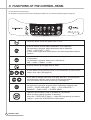
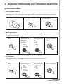
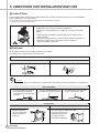
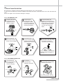
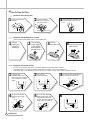
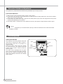
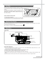
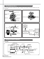
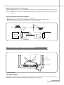
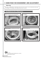
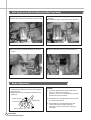
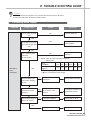
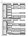
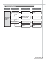
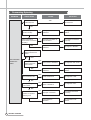
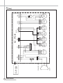
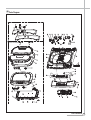
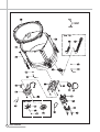
S/M No. : Service Manual Washing Machine Model: DWF-900S ✔ Caution : In this Manual, some parts can be changed for improving, their performance without notice in the parts list. So, if you need the latest parts information, please refer to PPL(Parts Price List) in Service Information Center (http://svc.dwe.co.kr). DAEWOO ELECTRONICS CORP. http : //svc.dwe.co.kr Aug. 2013 AUTO WASHER AUTO WASHER AUTO WASHER AUTO WASHER AUTO WASHER AUTO WASHER AUTO WASHER AUTO WASHER AUTO WASHER AUTO WASHER AUTO WASHER AUTO WASHER AUTO WASHER AUTO WASHER AUTO WASHER AUTO WASHER AUTO WASHER AUTO WASHER AUTO WASHER AUTO WASHER AUTO WASHER AUTO WASHER AUTO WASHER AUTO WASHER AUTO WASHER AUTO WASHER AUTO WASHER AUTO WASHER AUTO WASHER AUTO WASHER AUTO WASHER AUTO WASHER AUTO WASHER AUTO WASHER AUTO WASHER AUTO WASHER AUTO WASHER AUTO WASHER AUTO WASHER AUTO WASHER AUTO WASHER AUTO WASHER AUTO WASHER AUTO WASHER AUTO WASHER AUTO WASHER AUTO WASHER AUTO WASHER AUTO WASHER AUTO WASHER AUTO WASHER AUTO WASHER AUTO WASHER AUTO WASHER AUTO WASHER AUTO WASHER AUTO WASHER AUTO WASHER AUTO WASHER AUTO WASHER AUTO WASHER AUTO WASHER AUTO WASHER AUTO WASHER AUTO WASHER AUTO WASHER AUTO WASHER AUTO WASHER AUTO WASHER AUTO WASHER AUTO WASHER AUTO WASHER AUTO WASHER AUTO WASHER AUTO WASHER AUTO WASHER AUTO WASHER AUTO WASHER AUTO WASHER AUTO WASHER AUTO WASHER AUTO WASHER AUTO WASHER AUTO WASHER AUTO WASHER AUTO WASHER WASHING MACHINE Contents 1. SPECIFICATIONS................................................................................................................... 2 2. STRUCTURE OF THE WASHING MACHINE ....................................................................... 3 3. FUNCTIONS OF THE CONTROL PANEL............................................................................. 4 4. WASHING PROCEDURE AND PROGRAM SELECTION FULL AUTOMATIC PROGRAM ..................................................................................................... 5 RESERVED WASHING .................................................................................................................. 7 PARTIAL PROCESS & COMBINATION ........................................................................................ 7 5. DIRECTIONS FOR INSTALLATION AND USE LOCATION OF WASHER ............................................................................................................... 8 DRAIN SYSTEM.............................................................................................................................. 8 HOW TO CONNECT THE INLET HOSE ....................................................................................... 9 HOW TO CLEAN THE FILTER..................................................................................................... 10 6. FEATURE AND TECHNICAL EXPLANATION FEATURE OF THE WASHING MACHINE................................................................................... 11 WATER CURRENT TO ADJUST THE UNBALANCED LOAD.................................................... 11 AUTOMATIC WATER SUPPLY SYSTEM .................................................................................. 11 AUTOMATIC DRAINING TIME ADJUSTMENT........................................................................... 12 SOFTENER DISPENSER............................................................................................................. 13 AUTOMATIC UNBALANCE ADJUSTMENT ................................................................................ 14 CIRCULATING-WATER................................................................................................................ 14 LINT FILTER ................................................................................................................................. 15 RESIDUAL TIME DISPLAY .......................................................................................................... 15 DRAIN MOTOR............................................................................................................................. 15 GEAR MECHANISM ASS’Y ......................................................................................................... 16 PRINCIPLE OF BUBBLE GENERATOR...................................................................................... 16 FUNCTIONAL PRINCIPLE OF BUBBLE WASHING MACHINE................................................. 17 7. DIRECTIONS FOR DISASSEMBLY AND ADJUSTMENT GEAR MECHANISM ASS’Y REPLACEMENT............................................................................. 18 MOTOR SYNCHRONOUS AND VALVE REPLACEMENT......................................................... 20 BRAKE ADJUSTMENT................................................................................................................. 20 8. THE REPAIR METHOD OF GEAR MECHANISM FOR CLUTCH SPRING PROBLEM THE STRUCTURE OF GEAR MECHANISM............................................................................... 21 HOW TO CHECK THE CLUTCH SPRING PROBLEM................................................................ 22 THE PROCESS OF DISASSEMBLE............................................................................................ 23 THE PROCESS OF ASSEMBLE.................................................................................................. 25 9. TROUBLE SHOOTING GUIDE CONCERNING WATER SUPPLY .................................................................................................27 CONCERNING WASHING ........................................................................................................... 28 CONCERNING DRAINING........................................................................................................... 29 CONCERNING SPINNING ........................................................................................................... 30 CONCERNING OPERATION ....................................................................................................... 31 10. PRESENTATION OF THE P.C.B ASS’Y ........................................................................... 32 APPENDIX WIRING DIAGRAM ....................................................................................................................... 33 PARTS DIAGRAM & PARTS LIST ............................................................................................... 35 CIRCUIT DIAGRAM ...................................................................................................................... 44 1. SPECIFICATIONS NO. 1 2 3 ITEM DWF-8100 POWER SOURCE AVAILABLE IN ALL LOCAL VOLTAGE POWER 50Hz 320W CONSUMPTION 60Hz 300W(110~127V)/340W(220V) MACHINE NET 28Kg/28.5Kg(pump) WEIGHT GROSS 31.5Kg/32Kg(pump) 4 DIMENSION(WXHXD) 560 X 948.5 X 570 5 MATERIAL OF INTERNAL TUB 6 WASHING PROGRAM STAINLESS STEEL FULL AUTOMATIC 6 PROGRAMS ( FUZZY, DELICATE, ECONOMY, BLANKET, BABY CARE, SPORTS WEAR ) 7 WATER LEVEL SELECTOR 8 OPERATING WATER PRESSURE 9 MAXIMUM MASS OF TEXTILE REVOLUTION 10 2 HIGH(55L), MID(45L), LOW(31L) 0.3ß∏f/ß≤ ~ 8ß∏f/ß≤ ( 2.94N/ß≤ ~ 78.4 N/ß≤ ) 6.0Kg WASH 125~145(50Hz), 130~150(60Hz) SPIN 710~725(50Hz), 760~785(60Hz) SUIT 50(50Hz), 60(60Hz) PER MINUTE 11 WATER CONSUMPTION 12 WATER LEVEL CONTROL 13 ANTINOISE PLATE 14 GAER MECHANISM ASS'Y 15 LINT FILTER O 16 SOFTENER INLET O 17 ALARM SIGNAL O 18 AUTO WATER SUPPLY O 19 FUNCTION FOR BUBBLE OPTION 20 AUTO RE-FEED WATER O 21 AUTO POWER OFF O SPECIFICATIONS APPROX 1301/CYCLE ELECTRONICAL SENSOR OPTION SPUR GEAR 2. STRUCTURE OF THE WASHING MACHINE The parts and features of your washer are illustrated on this page. Become familiar with all parts and features before using your washer. NOTE • The drawing in this book may vary from your washer model. They are designed to show the different features of all models covered by this book, Your model may not include all features. • Page references are included next to same features. Refer to those pages for more information about the features. • HOT WATER TAP After using the washer, close the water tap. In case of the single valve model, there is no hot water valve. • COLD WATER TAP After using the washer, close the water tap. • BLEACH INLET • DETERGENT CASE • CONTROL PANEL • POWER SWITCH • GROUND WIRE In case of 3-wire power cord, ground wire will not be provided • POWER CORD • DRAIN HOSE • ADJUSTABLE LEG ■ Accessories HOSE ADAPTER UNDER COVER(OPTION) HOSE CONNECTOR(OPTION) P U In case of screw shaped inlet hoses water tap adapters will not be provided. DRAIN HOSE NON PUMP MODEL INLET HOSE(OPTION) CONNECTOR INLET(OPTION) PUMP MODEL STRUCTURE 3 3. FUNCTIONS OF THE CONTROL PANEL Control panel has micom sensor. As the buttons are pressed, the lamps indicating the selection of your desired washing program will light up. • Press this button to turn the power 'ON' or 'OFF'. • It can be used to choose water temperature to be suppliued. • As the button is pressed, water temperature will be repeated. COLD → COLD+HOT → HOT • In case of the single valve model, there is no wash temperature selector function. • It can be used to adjust amount of water according to the size of the load to be washed. • As the button is pressed, water level is selected by MID → HIGH → SMALL → LOW • It can be used to pre-engage time for wash. • It is the button for the partial process or the combination of each process (wash, rinse, spin) (See page 10) • If you want to change wash time, rinse time, spin time , you must press this button after selecing each process by the process button. Also, this button can be used to spin only. (See page 10) • It can be used to select the full-automatic program. • As the button is prassed, program will be selected by following order: FUZZY → FUZZY+DELICATE → ECO. → ECO.+DELICATE → BLANKET → BABY CARE → SPORTS WEAR • Operation and temporary stop is repeated as it is pressed. • When you want change program in operating; press the " START/HOLD" button → select the program that you want to change → press the "START/HOLD" button again. 4 CONTROL PANEL 4. WASHING PROCEDURE AND PROGRAM SELECTION ⏿ Full Auromatic Program 1. FUZZY PROGRAM ( SENSOR ); • This selection is for general washing except extraordinary clothes. • Artificial brain sensor selects properly the various kind of washing condition such as washing time, rinse times, spin time and water level. Procedure to press the button; 1. Put in the clothes. 2. Press the power switch. 3. Press the Start/Hold button, and close the lid. 2. DELICATE PROGRAM ; • This selection is effective for blue-jean, climbing clothes, rucksack, sports wear, etc ... • Procedure to press the button; 1. Press the power switch. 2. Press the program selection button for "DELICATE" ᵃ ᵄ ᵃ ᵃ ᵃ ᵃ fuzzy delicate economy blanket baby@care sprots@wear 3. Press the Start/Hold button, and close the lid. ᵃ ᵄ ᵃ ᵃ 4. Press the Start/Hold button, and close the lid. high mid low small 3. ECO. PROGRAM ; • This selection is useful to reduce water consumption and washing time for less dirty clothes. Procedure to press the button; 1. Press the power switch. 2. Press the program selection button for "ECO." ᵃ ᵃ ᵄ ᵃ ᵃ ᵃ fuzzy delicate economy blanket baby@care sprots@wear 3. Press the Start/Hold button, and close the lid. ᵃ ᵃ ᵄ ᵃ 4. Press the Start/Hold button, and close the lid. high mid low small PROCEDURE 5 4. BLANKET PROGRAM ; • This selection is effective for blanket or duvet. • If you want to soak, press the program button to adjust to " Blanket ". • Procedure to press the button; 1. Press the power switch. 2. Press the program selection button for "Blanket". ᵃ ᵃ ᵃ ᵄ ᵃ ᵃ fuzzy delicate economy blanket baby@care sprots@wear 3. Select the water level proper to the wash load. ᵃ ᵄ ᵃ ᵃ 4. Press the Start/Hold button, and close the lid. high mid low small 5. BABY CARE PROGRAM ; • This selection is effective for suit(wool) clothes. (1.2Kg's limitation for 1-time wash ) • Do not put leather clothes, or chamios clothes into the washing tub for washing. It may cause shringage or deforamation to the clothes. • Please use the neutral detergents only. • The water temperature is fixed to "COLD". • The water level "LOW" is not selected. Procedure to press the button; 1. Press the power switch. 2. Press the program selection button for "BABY CARE". ᵃ ᵃ ᵃ ᵃ ᵄ ᵃ fuzzy delicate economy blanket baby@care sprots@wear 3. Select the water level proper to the wash load. ᵃ ᵄ ᵃ ᵃ 4. Press the Start/Hold button, and close the lid. high mid low small 6. SPORTS WEAR PROGRAM ; •This selection is effective for heavily soiled clothes. • If you want to soak, press the program button to adjust to " Sports Wear" . Procedure to press the button; 1. Press the power switch. 2. Press the program selection button for "SOAK" ᵃ ᵃ ᵃ ᵃ ᵃ ᵄ 6 PROCEDURE fuzzy delicate economy blanket baby@care sprots@wear 3. Select the water level proper to the wash load. ᵃ ᵄ ᵃ ᵃ high mid low small 4. Press the Start/Hold button, and close the lid. ⏿ Reserved Washing 1. FUZZY PROGRAM ( SENSOR ); • Reservation can be made form 2 hours to 48 hours. • To make reservation to complete washing in 8 hours. spin time and water level. Procedure to press the button; Select the program Adjust to water level and water temperature "--" shall blink adjust to "8" • Now the reservation is made. • If you want to check the selected program, press the “START/HOLD” button again. ⏿ Partial Process & Combination • Press the Power button first. WASH TIME CONTROL • As the control button is pressed, wash time will be repeated as 12 → 13 → 14 → … → 20 → 30 → 0 → 0min. • If you don t want wash process, you must adjust wash time to 0 min. RINSE TIMES CONTROL • As the control button is pressed, Rinse time will be repeated as following; 2 → 3 → 4 → 0 → 1 time(s) • If you don t want Rinse process, you must adjust Rinse times to 0 times. SPIN TIME CONTROL • As the control button is pressed, spin time will be repeated as following; 5 → 7 → 9 → 0 → 1 → 3min. • If you don t want spin process, you must adjust spin time to 0 min. • Press the Start button. ⏿ Convenient Operation For Spin Only • If you want spin only, it is convinient to operate the button as following. PROCEDURE 7 5. DIRECTIONS FOR INSTALLATION AND USE ⏿ Location Of Washer Check location where washer will be installed. Make sure you have everything necessary for correct installation. Proper installation is your responsibility. • Do not place or store your washer below 0˚C(32˚F) to avoid any damage from freezing. • Install the washer on the horizontal sold foor. C If the washer is installed on an unsuitable floor, it could make considerable noise, vibrate and cause a malfunction. If washer is not level, adjust the front leg(A) up or down for horizontal setting. • Earthed electrical outlet(B) is required with 20cm of bottom back of washer cabinet. • Hot and cold water faucets (C) must be within 1M of the upper back of the washer cabinet and provide water pressure 0.3kgf/cm28kgf/cm2(2.94N/cm2-78.4N/cm2). B A UP DOWN ⏿ Drain System Never forget to install drain hose before operating your washer. The packing box is opened, there are a drain hose. • Conect the drain hose to the drain outlet at the back side of the washer. Non-Pump Model Pump Model Drain Outlet Drain hose Drain hose NOTES The opening must not be obstructed by carpeting when the washing machine is installed on a carpeted floor. Non-Pump Model 1 In case that it goes over a door sill. Don’t let the height of the drain hose exceed 20cm from the bottom of washer. 2 In case of extending the drain hose. Don’t let the total length exceed 3m. 3 Be careful that the end of the drain hose is not immersed in water. 3m 20Cm Pump Model Laundry tub drain system • Top of tub must be at least 86cm (34inches) high and no higher than 130cm from bottom of washer (A) 8 DIRECTIONS Standpipe drain system A • Needs a 3cm minimum diameter standpipe with minimum carry away capacity of 30liters per minute. • Top of tub must be at least 86cm(34inches) high and no higher than 130cm B from bottom of washer (B) ⏿ How to Connect the Inlet Hose Be careful not to mistake in supplying between the hot(maximum : 50˚C) and cold water. In using only one water tap or in case of attached one water inlet valve, connect the inlet hose to the cold water inlet valve. Do not over tighten : this could cause damage to couplings. FOR ORDINARY TAP 1 Pull down the collar of the inlet hose to separate it from the water tap adapter. 2 Loosen the four screws at the water tap adapter, but don’t loosen the screws until they are separated from the water tap adapter. 3 Connect the water tap adapter to the water tap and tighten the four screws evenly while pushing up the adapter so that the rubber packing can stick to the water tap tightly. ᵏ collar 4 Remove the tape, and screw connector B into connect A tightly. TAPE 5 Connect the inlet hose to the water tap adapter by pulling down the collar of the hose end. 6 Connect the inlet hose adapter of the hose to the water inlet of the washer by turning it clockwise to be fixed tightly. Connector A Connector B • Please check the rubber packing inside the inlet hose adapter of the hose. FOR SCREW-SHAPED TAP 1 Connect the inlet hose to the water tap by screwing the connector D tightly. 2 Connect the connector-inlet supplied if necessary. 3 Insert the inlet hose adapter into the water inlet of washer and turn it to be fixed. Connector Inlet Connector D Rubber Packing Connector D Inlet Hose Connector C Hose Rubber Packing Connector C • Assert the packing in the inlet CONNECTION 9 ⏿ How To Clean The Filter CLEANING THE LINT FILTER 1 2 Pull the Filter frame upward. Turn the lint filter inside out, wash the lint off with water. Lint Filter 3 Return the filter as it was, and insert the filter frame into the slot. Filter Frame CLEANING THE WATER INLET FILTER • Clean the filter when water leaks from the water inlet. 1 Pull the power plug out before cleaning it. 2 Turn off the water supply to the washer and separate the inlet hose. 3 Pull the inlet filter out. 4 Remove the dirt from the inlet filter with a brush. CLEANING THE DRAIN FILTER • In case of “U” shaped drain hose, this filter’s equipped at the back side of washer. • This drain filter is to screen the foreign stuffs such as threads, coins, pins, buttons etc .. • If the drain filter is not cleaned at proper time (every 10 times of use), drain problem could be caused. 1 Put down the remained water in the hose. And put a container under the filter to collect water. 2 Turn the cap counterclockwise. 3 Pull out the filter assembly off the case of the main body. FILTER SLIT CASE CAP CAP FILTER 4 CONTAINER Clean the drain filter removing the foreign stuffs. FILTER 5 Put in the filter along the guiding prominence of the case. Please note the left position of the filter adjusting the groove to the guide rib. FILTER GUIDE RIB CAP SLIT CONNECTION Turn the cap clockwise tightly. CASE CAP 10 6 CAP 6. FEATURE AND TECHNICAL EXPLANATION Feature of the Washing Machine 1 The first air bubble washing system in the world. 2 Quiet washing through the innovational low-noise design. 3 The wash effectiveness is much more enhanced because of the air bubble washing system. 4 The laundry detergent dissolves well in water because of the air bubble washing system. 5 The adoption of the water currents to adjust the unbalanced load. 6 One-touch operation system. Water Current to Adjust the Unbalanced Load It is a function to prevent eccentricity of the clothes after wash by rotating pulsator C.W and C.C.W for 35 seconds.(But, the SUIT course have no operation of the water currents to adjust the unbalnced load.) EFFECT It reduces vibration and noise effectively while spinning. WATER FLOW WASH DRAIN MOTOR C.W SINGAL C.C.W TIME(SEC.) SPIN 0.4 FILL RINSE 1 0.4 0.4 DRAIN 0.4 SPIN 0.4 FILL RINSE 2 0.4 ••••••• DRAIN ••• 40 SEC. (About 25 Times) * When the water level is “HIGH” Automatic Water Supply System The water level would be lowered because the clothes absorbs water at the beginning of washing. Therefore, after 60 seconds, the operation is interrupted to check the water level, and then the water is supplied again until the selected water level is reached. EXPLANATION 11 Automatic Drainning time Adjustment This system adjusts the draining time automatically according to the draining condition. Draining condition Good draining The washer begins spin process after drainage. Bad draining Draininig time is prolonged. No draining Program is stopped and gives the alarm. FUNCTIONAL PRINCIPLE 1 The micom can remember the time from the begining of drain to reset point when the pressure switch reaches to “OFF” point Drain Time Less than Movement of the Program Continue draining 10 minutes More than Program stops and gives the alarm with blinked on display lamp. 10 minutes 2 In case of continuous draining, residual drain time is determined by micom. Draining time as a whole = D + 40 Residual drain time. The time remembered by micom. 12 EXPLANATION Softener Dispenser This is the device to dispense the softener automatically by centrifugal force. This is installed inside the auto-balancer. FUNCTIONAL PRINCIPLE 1 Softener stays in room (A) when poured into softener inlet. 2 Softener moves from (A) to (B) by centrifugal force during intermittent spin process. 3 Softener flows from (B) to (C) during rinse process next to intermittent spin. 4 Softener moves from (C) to (D) by centrigfugal force during second intermittent spin. After spin process is finished, the softener is added into the tub through softener outlet. FLOW OF THE SOFTENER Wash Normal Program Intermittent Spin Centrifugal force (A) (B) Hold Intermittent Spin Rinse Flow in Centrifugal force Flow in (C) Spin (D) FLOW OF THE SOFTENER INSIDE OF THE BALANCER Room inside the balancer A B C D Centrifugal force Flowing by weight NOTES Softener moves into the next room when r.p.m of the tub is more than 100 r.p.m. HOW TO CHECK MOVEMENT Pour a reasonable amount of “MILK” into softener dispenser and operate the washer with no load. In final rinse cycle, make sure that the milk is added into the tub through softener outlet. Balancer Softener outlet B A D C Softener inlet EXPLANATION 13 Automatic Unbalance Adjustment This system is to prevent abnormal vibration during intermittent spin and spin process. FUNCTIONAL PRINCIPLE 1 When the lid is closed, the safety switch contact is “ON” position. 2 In case that wash loads get uneven during spin, the outer tub hits the safety switch due to the serious vibration, and the spin process is interrupted. 3 In case that P.C.B. ASS’Y gets “OFF” signal from the safety switch, spin process are stopped and rinse process is started automatically by P.C.B. ASS’Y. 4 If the safety switch is operated due to the unbalance of the tub, the program is stopped and the alarm is given. NOTES The alarm finished when you close the lid after opening it. Check the unbalance of the wash load and the installation condition. Circulating-Water CIRCULATING-WATER The washing and rinsing effects have been improved by adopting the water system in which water in the tub is circulated in a designed pattern. When the pulsator rotates during the washing or rinsing process, the water below the pulsator vanes creates a water currents as shown in figure. The water is then discharged from the upper part of the tub through the water channel. About 40 L/min. water is circulated at the ‘high’ water level, standard wash load and standard water currents. 14 EXPLANATION Filter Water channel Pulsator Tub Outer tub Lint Filter Much lint may be obtained according to the kind of clothes to be washed and some of the lint may also sticks to the clothes. To minimize this possibility a lint filter is provided on the upper part of the tub to filter the wash water as it is discharged from the water channel. It is good to use the lint filter during washing. Filter Filter Bleach Bleach Inlet Inlet Pulsator Pulsator HOW TO REPLACE LINT FILTER 1 Pull the filter frame upward. 2 Turn the lint filter inside out, and wash the lint off with water. 3 Return the filter as it was, and fix the filter frame to the slot. Residual Time Display When the START/HOLD button is pressed, the residual time (min.) is displayed on the time indicator, and it will be counted down according to process. When operation is finished, the TIME INDICATOR will light up . Drain Motor STRUCTURE Pull Loosen Pulley Lever Inductive ring Magnet Coil of motor Magnet of motor FUNCTIONAL PRINCIPLE 1 When the DRAIN MOTOR connected to the power source, the DRAIN MOTOR rotates with 900 r.p.m and revolves the pulley by gear assembly for reducing. 2 When the pulley is rotated, the pulley winds the wire to open the drain valve. 3 Therefore, rotation of pulley changed to the linear moving of wire. 4 The wire pulls the brake lever of Gear Mechanism Ass’y within 5 seconds. 5 After the wire pulled, gear assembly is separated from motor and condition of pulling is held by operation of the lever. 6 When the power is turned off, the drain valve is closed because the wire returns to original position. EXPLANATION 15 Gear Mechanism Ass’y The proper water currents is made by the rotation of pulsator at a low speed to prevent the damage to the small sized clothes. Pulsator shaft Spin shaft One way clutch bearing Gear unit as Sun gear Internal gear Planetary gear Clutch spring Brake lever Clutch boss Gear pulley Motor Pulsator 1490 r.p.m (50Hz) Gear unit as 1 revolution Motor Pulsator Gear Unit as Gear Pulley 5 revolutions 138 r.p.m 720 r.p.m Gear pulley Directly Tub 720 r.p.m V-belt Principle of Bubble Generator STRUCTURE Bobbin & coil Magnet Armature Bellows Trans core Air Air Air out hole Protector A Air in hole Protector B 16 EXPLANATION PRINCIPLE OF INTAKE & OUTLET OF THE AIR INTAKE : ARMATURE moves up, and BELLOWS inhales the air. At the same time, protector B is open and A is close. OUTLET : ARMATURE moves down, and BELLOWS exhausts the air. At the same time, protector B is close and A is opend. FUNCTIONAL PRINCIPLE OF TRANS & MAGNET ᵄ The phase of A.C electric power changes to 60 cycle/second. ᵄ The magnetic pole of trans core is changed by the change of the phase of A.C electric power. ᵄ The core repeats push and pull (3600 times/min.) of the armature magnet. A.C A.C N S LEAF SPRING NS TRANS CORE NS S N MAGNET Functional Principle of Bubble Washing Machine Air bubble Tub Outer tub Pulsator ACROSS SECTION FUNCTIONAL PRINCIPLE Bubble generator supplies the air from the bottom of outer tub to the inner space of pulsator, the air is dispersed by the rotation of pulsator. Air-bubble is created by the centrifugal force, and rises up. EXPLANATION 17 7. DIRECTIONS FOR DISASSEMBLY AND ADJUSTMENT Warning BEFORE ATTEMPTING TO SERVICE OR ADJUST ANY PART OF THE WASHING MACHINE, DISCONNECT THE POWER CORD FROM THE ELECTRIC OUTLET. Gear Mechanism Ass’y Replacement ᵄ Raise the top plate on the outer cabinet. ᵄ Remove outer tub cover from the tub ass’y. ᵄ Loosen the pulsator mounting screw and remove ᵄ Remove the spinner shaft flange nut by using ‘T’ ᵄ Remove the tub ass’y. type box wrench. NOTES To assemble the gear mechanism ass’y, reverse the disassembly procedure. 18 DIRECTIONS the pulsator. ᵄ Lay the front of the washer on the floor. ᵄ Remove four bolts mounting the plate-gear protect by ᵄ Remove four bolts mounting the gear mechanism ass’y by using a box wrench. using a box wrench and remove plate-gear protect. ᵄ Remove the V-belt. ᵄ Pull out the gear mechanism assy. DIRECTIONS 19 Motor Synchronous And Valve Replacement(Non Pump Model) ᵄ Lay the front of the floor. ᵄ Loosen two special screw and motor synchronous. ᵄ Take out the wire of motor synchonous from the bracket. ᵄ Separate the motor sycnchronous from the base. ᵄ Turn the valve by using screw driver as shown in picture. ᵄ Remove the valve lid from the valve drain assy. Brake Adjustment ᵄ Loosen the adjustment bolt and turn the adjustment bolt until the end of the bolt touches to the brake lever. ᵄ Tighten the lock nut and apply a small amount of paint-lock. Adjustment bolt Clutch lever Gear mechanism ass'y 20 DIRECTIONS Brake lever NOTES: 1. The brake adjustment has been made at the factory, so that it is not re-adjust. However, in case of insufficient brake operation, problem the upper procedure. 2. Overtightening of the adjustment bolt will cause poor brake performance. 3. Undertightening of the adjustment bolt will cause continuous braking and thereby. cause the problems of the motor during the spingcycle. 8. THE REPAIR METHOD OF GEAR MECHANISM FOR CLUTCH SPRING PROBLEM The structure of gear mechanism Clutch Lever Bearing Clutch Boss Clutch Tip Clutch spring Coupling Pulley Spring Washer Fastening Nut Pulley Shaft Clutch Boss Ass’y Pulley Shaft Fastening Nut Coupling Spring Washer Drum plate Pulley ᵄTOOL FOR REPLACING THE CLUTCH BOSS ASSEMBLEᵄ Tool name Specification Q’ty Fixing jig 1 Ratchet handle 1 Socket and extension bar Some cotton yarn socket : 10mm, 17mm per each some THE REPAIR 21 how to check the clutch spring Problem PROBLEM 1) THE LAUNDARY IS IN THE SPIN TUB UNEVENLY WHEN JUST STARTING SPIN PROCESS. 2) THEREFORE, IT CAUSE THE SERIOUS NOISE AND VIBRATION WHEN WASHING AND SPINNING PROCESS OR SUPPLING WATER IRREGULARY WHEN SPINNING PROCESS AND CAUSE SHORT OF SPIN PERFORMANCE. CHECKING METHOD IN THIS CASE, YOU MUST EMPTY THE SPIN TUB FIRST. 1) TO CHECK THE REVOLUTION OF SPIN TUB. IF THE SPIN TUB DOES NOT REVOLVE AND ONLY THE PULSATOR IS TURNING, THAT IS CLUTCH SPRING DEFECT. 2) TO CHECK THE SPIN SPEED(RPM) BETWEEN SPIN TUB AND PULSATOR. IF YOU FIND THE DIFFERENT SPIN SPEED BETWEEN SPIN TUB AND PUSATOR, THIS IS ALSO CLUTCH SPRING DEFECT. IN THIS CASE, WE ARE GOING TO SUPPLY THE CLUTCH BOSS ASSEMBLY INSTEAD OF GEAR MECHANISM ASSEMBLEY. PLEASE REFER TO FOLLOWING FIG. THE CLUTCH BOSS ASSEMBLY NO. PARTS NAME SPECIFICATION CODE Q’TY 1 CLUTCH SPRING 1.5*1.5 3615110000 1 2 CLUTCH BOSS PP 3619301300 1 3 GREASE beacon#325 3g PACKING PACKING THE CLUTCH BOSS ASS’Y METHOD BY USING VINYL PACK CLUTCH BOSS ASS’Y PART CORD : 3610028000 22 THE REPAIR 1 The Process Of Disassemble Disassemble 1 No. Process Notice Use wrench or driver - ratchet handle - extension bar - socket : 10mm 1 Remove the protector Release screws marked 4-point 2 Remove the v-belt Use fixing jig for pulley as to see fig 1. and 17mm-socket for nut 3 Loosen the fastening nut Take out plain washer if it has 4 Disassemble the spring washer THE REPAIR 23 Disassemble 2 No. 5 Process Notice Disassemble the pulley Catch the boss and pull upward with spiral rotate in the clockwise direction 6 Disassemble the clutch boss assembly 7 Separate coupling from clutch boss ass’y Clean the drum plate, coupling surface and contact face between drum plate and coupling 8 24 THE REPAIR Cleaning It is necessary to keep cotton piece goods being dry and clean The Process Of Assemble Assemble 1 No. Process Notice Check the uneven face of coupling is assembled upward 1 Assemble the coupling 2 Assemble the new clutch boss ass’y 3 Assemble the pulley - Push in the clutch boss ass’y with rotating on the clockwise direction. - After assembling, rotate on the clockwise more 2~3 teeth and pull out the pulley shaft upward If there was plain washer, you have to assemble plain washer the first and then assemble spring washer 4 Assemble the spring washer THE REPAIR 25 Assemble 2 No. Process Assemble the fastening nut 5 6 Notice - Use fixing jig and 17mm socket wrench as if disassembling, as fastening torque about 100~200kgf-cm. - Check the end-play, up and downward and check the binding force, too much or not on bi-direct of rotation. Assemble the Belt 7 Assemble the protector keep distance 2~3mm Synchronous Motor 8 Final checking Clutch Tip 3.5~4.5 26 Drain Valve THE REPAIR Finally, check the distance between brake lever and control bolt. (2~3mm) Also, check the interferance depth both clutch tip and clutch boss(3.5~4.5mm) 9. TROUBLE SHOOTING GUIDE NOTES 1. When replace the P.C.B. ASS’Y do not scratch the surface of the P.C.B. ASS’Y. 2. Disconnect the power cord from the electric outlet. Concerning Water Supply PROBLEM CHECK POINT CAUSE Do you open the water tap? NO SOLUTION Open the water tap. YES YES Is the filter of the water inlet valve clogged with dirt? Clean the filter. NO WATER IS NOT SUPPLIED. Increase the water pressure. NO Is the water pressure sufficient? (0.3~8 kgf/cm2) NOTE : Open the water tap fully and measure the flow rate. Flow rate(l/min.) Water pressure (kgf/cm2) YES 11.5 15.0 18.0 20.3 24.1 27.4 0.3 0.4 0.5 0.6 0.8 1.0 From the upper results, you know that the flow rate more than 11.5l/min. is essential for water supply. Does the water inlet valve make operating sound? NO Water inlet valve is defective. Change water inlet valve. Improper connection of the connector or the terminal. Connect the connector or the terminal properly. P.C.B AS is defective. Change the P.C.B AS. Lead wire is defective. Change the lead wires. YES Is the connector or the terminal connected properly? NO YES Is the output voltage of the P.C.B normal? NO YES TROUBLE SHOOTING 27 PROBLEM CHECK POINT Does the water supply continue while the power is turned off? CAUSE SOLUTION YES The water inlet valve is defective. Change the water inlet valve. YES The triac of P.C.B is defective. Change the P.C.B ASS’Y. NO Does the water supply start as soon as you press the power switch? NO WATER SUPPLY IS NOT STOPPED. Operate the washer after setting the water level to “HIGH” NO Does the water supply continue after the water reaches to the “HIGH” level? YES Is the air tube of water level switch kinked or deformed? Normal operation. YES NO Air tube is defective. Change the air tube. Pressure switch is defective. Change the pressure switch. Concerning Washing PROBLEM CHECK POINT CAUSE SOLUTION Does the motor operate after finishing water supply? NO YES Does pulsator rotate in only one direction? YES The triac of P.C.B is defective. NO THE PULSATOR DOES NOT ROTATE EVEN IF THE WATER IS SUPPLED. YES NO Is the motor coil disconnected? YES Is the V-belt worn out? NO TROUBLE SHOOTING Normal Does the motor make operating sound? Is the connection condition of capacitor terminal good? 28 Change the P.C.B ASS’Y. YES NO Motor is defective. Improper connection YES V-belt is defective. Change the motor. Connect the terminal properly. Change the V-belt. Change the motor. Concerning Draining PROBLEM CHECK POINT Do you install the drain hose properly? CAUSE NO SOLUTION Improper installation Install the drain hose properly. Malfunction of drainage by the foreign matter Remove the foreign matter from the pump housing Drain pump is defective Change the Drain pump P.C.B ASS’Y is defective. Change the P.C.B ASS’Y. YES THE WASHER DOES NOT DRAIN. Is the foreign matter accumulated inside the pump housing? YES NO Is the output voltage of the drain pump normal? NO YES TROUBLE SHOOTING 29 Concerning Spinning PROBLEM CHECK POINT CAUSE SOLUTION YES Close the lid. Is the lid open? NO Does the safety switch operate normally? NO Safety switch is defective. Change the safety switch. NO Improper connection of the connector. Connect the connector properly. P.C.B. ASS’Y is defective. Change P.C.B ASS’Y. Drain motor is defective. Change the drain motor. P.C.B ASS’Y is defective. Change the P.C.B ASS’Y. V-belt is defective. Change the V-belt. Motor is defective. Change the motor. Improper connection. Connect the terminal correctly. P.C.B ASS’Y is defective. Change the P.C.B ASS’Y. YES Is the connector of P.C.B ASS‘Y connected properly? YES Does the pulsator rotate while the tub does not rotate? NO THE WASHER DOES NOT SPIN. YES Is the input voltage of the drain motor normal? YES NO YES Is the V-belt worn out? NO Is the input voltage of motor normal? YES NO Is the connection condition of capacitor terminal good? YES 30 TROUBLE SHOOTING NO Concerning Operation PROBLEM CHECK POINT CAUSE SOLUTION NO Is the plug connect-ed to electric outlet? Connect the plug. YES YES THE INDICATOR LAMPS(L.E.D) DO NOT LIGHT UP WHEN THE POWER BUTTON IS PRESSED. Is Fuse opended? Change Fuse NO Is the condition of power button good? NO MOTOR ROTATES WHEN START/HOLD BUTTON IS NOT PRESSED. ABNORMAL NOISE DURING WASH PROCESS. Change P.C.B ASS’Y. Improper connection of the connector. Connect the connector properly. P.C.B. ASS’Y is defective. Change P.C.B ASS’Y. YES Is the connector of the P.C.B. ASS’Y connected properly? NO YES PROGRESS LAMPS(LED) DO NOT LIGHT UP. Power button is defective Do you press START/HOLD button? NO YES Does the pressure switch operate normally? NO Check the output voltage of P.C.B ASS’Y NO Is the V-belt worn out? P.C.B ASS’Y is defective. Replace P.C.B ASS’Y. Pressure switch is defective. Change the pressure switch. Abnormal YES Is the strange noise generated when the pulsator rotates in TEST MODE of P.C.B ASS’Y? Press START/HOLD button. YES YES P.C.B ASS’Y is defective Change P.C.B ASS’Y. There is foreign matter between pulsator and tub. Remove the foreign matter. V-belt is defective. Change the V-belt. TROUBLE SHOOTING 31 10. PRESENTATION OF THE P.C.B ASS'Y Concerning Error Message MESSAGE CAUSE SOLUTION Improper installation of drain hose. Install drain hose properly. The drain hose is blocked up by foreign matter. Remove foreign matter from drain hose. Drain motor is inferior. Change drain motor. The water tap is closed. Open the water tap. The water inlet filter clogged. Clean the water inlet filter. It passes over the 30 minutes, yet it doesn’t come to assigned water level. Check whether or not is comes to the assigned water level. Wash loads get uneven during spin. Re-set wash loads evenly. Poor installation of the unit. Proper installation. The lid is opened. Close the lid. The safety switch is inferior. Change the safety switch. The load sensing is inferior. After the load sensing operates about 7 seconds, the message is displayed during 1 second and water level is always fixed ‘high’. The water level sensing is inferior. Change the P.C.B. ASS’Y. Check the water level sensor and the contact part of the connector. * If the display error message shown UE or LE, please check the both message's causes and solutions. 32 PCB ASS'Y 110V~ POWER CORD 1 2 2 2 3 1 1 MOTOR 2 3 BL/YW 1 WH/RD FUSE WH 1 2 DRAIN MOTOR 1 2 CONDENSOR 2 1 1 1 3 COLD VALVE OR YW/BK 2 PRESSURE SENSOR 2 1 WH WH BL BK VT BL 2 1 YW 2 SWITCH SAFETY DOOR SWITCH BR GR RD VT 3 3 4 1 DOOR LOCK 3 4 SWITCH 2 2 NT 1 BL M - PCB BL BK WH F-PCB APPENDIX ⏿ Wiring Diagram [non-pump] WIRING DIAGRAM 33 220V~ POWER CORD 1 1 2 2 1 2 3 1 MOTOR 2 3 1 2 2 1 1 2 DRAIN DRAIN HOT MOTOR PUMP VALVE 1 2 2 BL/YW CONDENSOR 2 WH/RD FUSE 1 1 WH GR 2 1 BL VT VT 1 YW/BK RD/BL YW RD BL/WH 3 2 BL 3 COLD VALVE OR YW/BK M - PCB PRESSURE SENSOR 2 1 WH WH WIRING DIAGRAM BK 34 1 YW 2 SWITCH SAFETY DOOR SWITCH BR GR F-PCB ⏿ [Pump] ⏿ Parts Diagram OPTION : PANEL B A18 A21 A19 A17 A20 A34 A22 A15 OPTION : DOOR AS A33 A32 A37 A35 A36 A38 A39 A41 A16 A42 A43 A02 A31 A03 A01 A30 A04 A42 A05 A06 A44 A07 A24 A25 A16 A15 A26 A26 A08 A09 A23 A10 A06 A27 A11 A14 A28 A13 A29 A12 PARTS DIAGRAM 35 ⏿ Parts List NO PARTS CODE DESCRIPTION Q'TY REMARK A01 PLATE T 3614548300 PP 1 A02 MOLD DECO DOOR B 36116DXJ00 ABS 1 A03 MOLD DOOR B 36117YDV00 ABS 1 A04 MOLD DECO DOOR F 36116DXK00 ABS 1 A05 MOLD DOOR F 36117YDW00 ABS 1 A06 HOOK DOOR 3613102400 ABS 1 A07 MOLD CAP HANDLE 3612615800 ABS 1 A08 GLASS DOOR OUTER 36117YDS00 ABS 1 A09 GLASS DOOR F 36117YDU00 ABS 1 A10 GLASS 3611A14700 GLASS 1 A11 GLASS DOOR INNER 36117YDT00 ABS 1 A12 SCREW A13 CUSHION DOOR 3611559900 NR 2 A14 DOOR HANDDLE 3612615700 ABS 1 A15 SPRING DOOR L 3615121000 SUS 1 A16 SPRING DOOR R 3615121000 SUS 1 A17 PANEL B 36142T6B00 PP 1 A18 CAP DRY 3610922500 PP 1 A19 CONNECTOR HOSE 3619506600 PS 1 A20 PACKING 3614004100 SILICON 1 A21 CAP WATER 3610922600 PP 1 A22 PANEL B 36142T6A00 PP 1 A23 PANEL F 36142T6C00 ABS 1 A24 CAP HOOK 3610922700 ABS 1 A25 DECORATOR FILM 36116DXL00 PC 1 A26 CAP REAR 3610902600 NR 2 A27 CAP SVC 3610922200 ABS 1 8100 Ěڏ A28 PCB AS PRPSSWU___ AC 110-130V, 60Hz 1 NON-PUMP PRPSSWU___ AC 220-240V, 50/60Hz 8100 Ěڏ 11 ॶ҉ۑ 2 VALVE A29 SCREW A30 CASE DETERGENT 36111T5Q00 PP 1 A31 NOZZLE 3618114100 PP 1 A32 LEVER SAFETY S/W 3613701800 POM 1 A33 PLATE LEVER 3614521400 PP 1 A34 SENSOR PRESSURE AS 3614801630 CDN15N, 180 ,3PIN 1 A35 MICRO SWITCH 3619045400 GSM-V16183A4, 250V/16A 1 A36 VALVE INLET 3615403332 AC 100-130V, 50/60Hz COLD 1 UPWARD 3615403731 AC 220-240V, 50/60Hz COLD 3615403332 AC 100-130V, 50/60Hz HOT 1 BACKWARD 3615403831 AC 220-240V, 50/60Hz HOT 3619045400 GSM-V16183A4, 250V/16A A37 A38 36 PARTS NAME VALVE INLET MICRO SWITCH PARTS DIAGRAM 4 1 NO PARTS NAME A39 Z-AIR_BUBBLE A40 HARNESS AS A41 A42 CORD POWER AS UNIT CAPACITER PARTS CODE DESCRIPTION Q'TY REMARK 1 3612787922 8A COLD BUBBLE 1 SAINGLE VALVE 3612787926 5A COLD BUBBLE 3612787930 8A COLD/HOT BUBBLE 3612787936 5A COLD/HOT BUBBLE 3612787940 8A COLD/HOT NON-BUBBLE 3612787946 5A COLD/HOT NON-BUBBLE 3612787970 8A COLD/HOT BUBBLE 3612787975 5A COLD/HOT BUBBLE 3612787980 8A COLD/HOT NON-BUBBLE 3612787985 5A COLD/HOT NON-BUBBLE 3611337000 F H05VV 3X0.75 1.9M WH 3611337100 RVCT 3611337200 N LFC-3R 3X0.75 1.9M GY AUSTRALIA 3611337300 F H05VV 3X0.75 1.9M WH ITALY 3611337400 RW-300/500 3X0.75 1.9M PR.CHINA 3611337500 VCTF 3X0.75 1.9M INDIA 3611339000 U VCTF 3X0.75 1.9M GY SOUTH KOREA 3611338200 F H05VV 3X0.75 1.9M BK PERU 3611338200 F H05VV 3X0.75 1.9M BK KUWAIT, OMAN 3611337710 BS-1363A MALAYSIA 3611338000 H05VV-F 3X0.75 1.9M SINGGAPORE 3611338100 A-VCTFK 2X0.75 1.9M GY TAIWAN 3611338200 F H05VV 3X0.75 1.9M BK EUROPEAN NATIONS 3611338300 C SJT 3X18AWG 1.9M GY PANAMA, USA 3611338400 H05VV-F 3X0.75 1.9M GY ARGENTINA 3611338500 H05VV-F 3X0.75 1.9M GY SOUTH AFRICA 3611337710 BS-1363A UAE 3618911600 8.4 400VAC CAN-TYPE 3618911900 30 200VAC CAN-TYPE 3618912000 33.6 3618959700 7.5 DUAL-VALVE, PUMP DUAL-VALVE 1 2X0.75 1.9M GY CHILE JAPAN 1 AC120-230V, 50/60Hz AC120-127V, 50/60Hz 200VAC CAN-TYPE AC110V, 60Hz 400VAC CAN-TYPE AC240V, 50Hz A43 HINGE DOOR 3612902400 POLYACETAL 2 A44 SWITH DOOR LOCK 3619048900 ENTI TECH 1 PARTS DIAGRAM 37 B08 B08 B07 B03 B07 B02 B09 B01 B02 B02 B04 B06 B06 B05 B10 38 PARTS DIAGRAM ⏿ Parts List NO PARTS NAME PARTS CODE DESCRIPTION Q'TY REMARK B01 CABINET 361081WS00 SGCC T=0.57 1 B02 HANDLE CABINET 3612603310 PP 2 B03 PLATE UPPER 3614521600 PP 1 B04 BASE U 3610396300 PP 1 B05 LEG ADJUST AS 3617702122 DWF-1089W2 1 B06 LEF FIX 3617703000 SBR 3 B07 HOLDER SUPPORT FL 3615306200 POM 1 HOLDER SUPPORT FR 3615306400 POM 1 HOLDER SUPPORT BL 3615306300 POM 1 HOLDER SUPPORT BR 3615306500 POM 1 B09 COVER BACK 3611413605 SPG 0.35T 1 B10 COVER UNDER 3611418500 PP 1 OPTION B11 HARNESS OUTER 3610068700 50/0.18GREEN ST710489-2 1 2-WIRE POWER CORD B12 HOSE DRAIN O AS 3613213560 LDPE L=950 1 NON-PUMP B13 HOSE DRAIN O AS 3613218860 LDPE/EVA L=1600 PUMP 1 PUMP B14 GUIDE DRAN HOSE 3612502300 PP 1 B15 UNIT DRAIN PUMP AS 3618962815 AC 220-240V/50Hz 1 B16 3618963015 AC 220V/60Hz B17 3618962905 AC 110-127V/60Hz B08 B18 PARTS DIAGRAM 39 C01 C11 C11 C02 C04 C05 C03 C12 C06 C13 C14 C15 40 PARTS DIAGRAM ⏿ Parts List NO PARTS NAME PARTS CODE DESCRIPTION C01 BALANCER AS 36161___00 DWF-900S C02 TUB I 3618832400 SUS 0.4T C03 TUB U 3618832500 HIPS C04 GUIDE FILTER 3612514100 DWF-900S C05 SPECIAL SCREW 3616051629 AUA 5.5X16 C06 PULSATOR AS 37197___00 DWF-900S C07 BALANCER AS 3616104500 DWF-5510PN C08 TUB I 3618808100 PP C09 GUIDE FILTER 3612503910 PP C10 PULSATOR AS 3619706600 DWF-750WTP C11 FILTER AS 4505E82002 POLYESTER 90X120 INSERT C12 SPECIAL SCREW 3616002901 SUS 304 NON-SILOCK C13 SPECIAL NUT 4507D83080 SUS 304 C14 FLANGE TUB 3617201100 5KG 3-FOOT C15 SPECIAL SCREW 3616007000 SCM24H,6.5X24 REMARK STAINLESS STEEL PLASTIC PARTS DIAGRAM 41 42 PARTS DIAGRAM ⏿ Parts List NO PARTS NAME PARTS CODE DESCRIPTION REMARK D01 COVER TUB O 3611434300 PP D02 TUB O 3618832300 PP D03 SUSPENSION AS F 36198___00 FRONT D04 SUSPENSION AS B 36198___00 REAR D05 VALVE DRAIN AS 3615408500 DWF-750M D06 HOSE DRAIN AS 3613227000 LDPE+EVA DWF-752MN D07 HOSE DRAIN AS 3613226900 LDPE+EVA DWF-800WNP PUMP D08 CLAMP 4507D08153 MFZN HOSE ID=7PIE OPTION ; PUMP D09 HOSE 4500D08210 ID=4.0 D10 CLAMP 4507D08153 MFZN HOSE ID=7PIE D11 HOSE 4500D08210 ID=4.0 D12 BASE 3610396400 EHI 1.6T D13 SPECIAL SCREW 3616007000 SCM24H 6.5X24 D14 DTAIN MOTOR 361895875L 220-240V/5,60Hz 361895872L 100-127V/60Hz NON-PUMP OPTION ; BUBBLE D15 GEAT MECHANISM 3617310511 GM-0600-KJ4P0 D16 BOLT HEX 7341801511 6B-1 8X15 SW MFZN D17 PROTECTOR GEAR 3618346700 SGCC 1.2T D18 SPECIAL WASHER 4505E34030 PP D19 UNIT MOTOR AS 3618959901 100-127V/60Hz W1S30CC004 3618960220 220V/60Hz W1S30VC007 3618960210 220-240V/50Hz W1S30VC006 7650802528 6B-1 8X25 PW MFZN 3618401480 DP=48.5 60Hz PRESS 60Hz 50Hz D20 BOLT HEX D21 D22 PULLEY MOTOR AS 3618401490 DP=53 50Hz PRESS D23 WASHER SPRING 7401008011 SW-8 MFZN D24 NUT HEX 7392800011 M8XP1.25 MFZN D25 BELT V 3616590210 M20 50Hz 3616590200 M19.5 50Hz 3612757010 L=560 D17 B18 HARNESS EARTH INNER PARTS DIAGRAM 43 ⏿ Circuit Diagram 44 CIRCUIT DIAGRAM DAEWOO ELECTRONICS CORP. 1-2, Jeo-dong 1(il)-ga, Jung-gu, Seoul, Korea C.P.O. BOX 8003 SEOUL, KOREA TELEX: DWELEC K28177-8 CABLE: “DAEWOOELEC” S/M NO. : PRINTED DATE: Aug. 2013 ABOUT THIS MANUAL vision@creativeL@incN Էܞ ړĸ ࣃۉʷ VѨێ ݖΟӂ˱ Tࠚ ɽ ʁ m@o@d@e@l ݘܖր ɮ dwfMYPPs s @manual ܂ ր m@@e@@m@@o RPQSNPXNPV ߭ TX QSNPXNPVMहݖL@ह˒ݖL@RL@SL@TL@UL@VL@WL@XL@SWL@SXL@SYL TPL@TQL@TRL@TSL@TU@֭Ŕ QW ِ͊ߏ vision ɽ ʁ і О ր telZ WSPMPVVP@faxZ WSPMSWXX