1
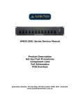
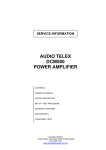
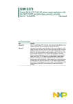
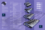
SERVICE INFORMATION
ACM604
MIXER AMPLIFIER
CONTENTS:
OPERATION MANUAL
SCHEMATIC DIAGRAMS
Australian Monitor
1 Clyde Street, Silverwater NSW 2128 Australia
+61 2 9647 1411
www.australianmonitor.com.au
ACM604
4 x 60w Mixer Amplifier
Operating Manual
ACM604, 4 x 60 Watt Mixer Amplifier
Product Description
The ACM604 is a 4 x 60 watt mixer amplifier designed for commercial installations. It features 4 independent 60 watt mixer
amplifiers within the one 2 rack unit chassis. Each amplifier features 3 balanced microphone/line input channels and
outputs for either low impedance (8 ohm) or 70v/100v line speaker systems. A host of unique features including VOX
muting, VCA master level control and optional tone generator/VOX relay cards make the ACM604 a very flexible
amplifier. The unit can be mounted in a standard 19” equipment rack (rack ears supplied) or it can be used on a shelf or
table.
Front Panel Features
Input Level Controls
The front panel is split into 4 sections, one for each mixer amplifier. The level controls for each amplifier are labelled MicLine 1 through to Mic-Line 3. These level controls are used to set up a suitable “mix” of all the various input sources
connected to each amplifier, for example microphones, CD players, cassette decks. If a master level control is desired per
amplifier, an external 500-1K ohm pot can be connected (per amplifier) to the rear panel for remote control of the master
level of each amplifier.
Bass Control
Each amplifier within the ACM604 includes a recessed, screwdriver adjustable 2 band equalisation system. The Bass
control allows the user to increase or decrease the amount of bass in the system. The control allows for 12dB of cut or
boost at 100Hz. If no bass cut or boost is required, the control should be left in the centre position.
Treble Control
Each amplifier within the ACM604 includes a recessed, screwdriver adjustable 2 band equalisation system. The Treble
control allows the user to increase or decrease the amount of treble in the system. The control allows for 9dB of cut or
boost at 10kHz. Generally, a small increase of the treble control makes a system sound ‘brighter’. If no treble cut or boost
is required, the control should be left in the centre position.
VCA Master Control
For applications requiring remote level control, provision has been made on the rear panel of the ACM604 to connect an
external 500-1K ohm pot for remote control of the master level of each amplifier.
Power Switch & “On” LED
The black rocker switch on the right hand side of the front panel is used to switch the amplifier on and off. The ‘up’
position is on. When the amplifier is connected to an appropriate AC power source and is switched on, the blue on LED
will illuminate.
Signal LED’s
The four green “Signal” LED’s located next to the On LED indicates that the ACM604 is passing audio. One LED is
provided per amplifier. The signal LED is a simple method to trouble-shoot installations especially in multi-amplifier
projects.
Rack Mounting
The ACM604 is supplied with rack ears attached to allow mounting within a standard 19” equipment rack. As is the case
with almost all audio products, adequate ventilation and air flow is required. When installing multiple ACM amplifiers
within the one rack, it is recommended that at least 1 rack unit of ventilation space is left between every two amplifiers.
For table or shelf mounting, the rack ears can be removed using a screwdriver. Once the rack ears are removed, please
reinstall the screws.
Rear Panel Features
AC Power Inlet
The 3 pin IEC power inlet is located on the bottom left of the rear panel and accepts a standard mains power lead fitted
with an IEC connector. Before plugging in a power lead, please check the rear panel of the amplifier to ensure that the
voltage label shows the correct AC operating voltage for your part of the world. The inlet is equipped with an in-built AC
fuse holder fitted with a 5 Amp slow blow fuse plus a spare fuse. Please ensure that the mains power cord is disconnected before attempting to check or replace this fuse. Power consumption is 400 watts (max).
Mic/Line Input Terminal Strip
Located on the top half of the rear panel are the input connections for all 4 amplifiers. Each amplifier will accept balanced
microphone or line inputs (selectable via an internal dip switch). Additionally, a remote pot can be connected to each
amplifier for external control of the master level.
The rear panel is split into four sections, one for each amplifier. Looking at the back panel and reading from left to right
the amplifiers are 4, 3, 2 and 1. In other words, the input and output section is directly behind the relevant front panel
controls.
The inputs are labelled Ch1, Ch2 and Ch3. All are balanced with the connection reading left to right as “Ground, +
positive, - negative”. Each input can be switched to be either mic or line level via a dip switch behind each input and
accessible through the top lid. Additionally, phantom power (+18v DC) is selectable per input. The dip switch settings
are:
Balanced Mic Level - 1 and 2 On
Balanced Line Level - 1 and 2 Off
Phantom Power (+18v) - 3 ‘On’ to enable phantom power or ‘Off’ to disable phantom power
VCA Remote Master Level Control
Located on the right side of each input terminal strip is a two position screw terminal block for an external pot. For remote
master level control, an external 500-1K ohm pot can be connected per amplifier.
Speaker Output Terminal Strip
Located on the bottom half of the back panel is the speaker output terminal strip. Four separate speaker output terminal
strips are provided, one for each amplifier. Looking at the back panel and reading from left to right the amplifiers are 4, 3,
2 and 1. In other words, the speaker output section is directly behind the relevant front panel controls.
Each of the four amplifiers in the ACM604 can work with 8 ohm and/or 70/100 volt line speakers systems.
The various outputs are marked as follows:
COM
8
Common or “-” for low impedance speaker loads (8 ohms).
Positive “+” for 8 ohm speaker loads (use with common)
COM
70
100
Common or “-” for 70v or 100v speaker loads (maximum load of 160 ohms at 100v)
Positive “+” for 70v line speaker loads (use with common)
Positive “+” for 100v line speaker loads (use with common)
Please ensure that the correct “Common” is used. Low impedance and 70/100v loads can be used simultaneously but
please pay careful attention to the overall speaker load. When used individually, the low impedance load should be 8
ohms or higher while the 100v line load should not fall below 160 ohms. When both outputs are used simultaneously,
ensure that neither output is loaded to maximum.
VOX Muting
The ACM604 includes a VOX muting circuit which is independent for each amplifier. The unit is factory set so that input
1 of each amplifier has VOX priority over inputs 2 and 3 for that amplifier. Basically, when signal is present on input 1,
audio from inputs 2 and 3 is muted. As mentioned, each amplifier is totally independent so the VOX circuit from one
amplifier does not affect any of the other amplifiers.
Muting can be defeated per amplifier via an internal jumper labelled JP2 (located on the top board behind inputs 1 and
2. The ACM604 is shipped with muting enabled (jumper towards the front panel of the amplifier). To disable VOX muting
per amplifier, simply move the relevant jumper (from amplifiers 1, 2, 3 or 4) so that it is closest to the back panel.
Optional ATC5489 Tone Generator/Vox Relay Card
An optional Tone Generator/Vox Relay card is available for the ACM604. Each card suits one amplifier within the unit so
up to 4 cards can be installed. The card slots in between the input terminal strip and the output terminal strip on the rear
panel of the amplifier. Simply remove the two screws and blanking plate, slide in the ATC5489 and replace the screws.
The card provides a 4 tone generator module (Pre-Announce, Bell, Alert and Evacuate tones) per amplifier and also
provides a VOX triggered relay output per amplifier. Full installation and operation instructions are included with the
ATC5489.
Important Safety Information
1. Save the carton and packing material even if the equipment has arrived in good condition. Should you ever
need to ship the unit, use only the original factory packing.
2. Read all documentation before operating your equipment. Retain all documentation for future reference.
3. Follow all instructions printed on unit chassis for
proper operation.
4. Do not spill water or other liquids into or on the unit,
or operate the unit while standing in liquid.
5. Make sure power outlets conform to the power requirements listed on the back of the unit.
6. Do not use the unit if the electrical power cord is
frayed or broken. The power supply cords should be
routed so that they are not likely to be walked on or
pinched by items placed upon or against them, paying
particular attention to cords and plugs, convenience receptacles, and the point where they exit from the
appliance.
7. Always operate the unit with the AC ground wire
connected to the electrical system ground. Precautions
should be taken so that the means of grounding of a
piece of equipment is not defeated.
8. Mains voltage must be correct and the same as that
printed on the rear of the unit. Damage caused by
connection to improper AC voltage is not covered by
any warranty.
9. Have gain controls on amplifiers turned down during
power-up to prevent speaker damage if there are high
signal levels at the inputs.
10. Power down & disconnect units from mains voltage
before making connections.
11. Never hold a power switch in the “ON” position if it
won’t stay there itself!
12. Do not use the unit near stoves, heat registers, radiators, or other heat producing devices.
13. Do not block fan intake or exhaust ports. Do not
operate equipment on a surface or in an environment
which may impede the normal flow of air around the
unit, such as a bed, rug, weathersheet, carpet, or completely enclosed rack. If the unit is used in an extremely
dusty or smoky environment, the unit should be periodically “blown free” of foreign matter.
14. Do not remove the cover. Removing the cover will
expose you to potentially dangerous voltages. There
are no user serviceable parts inside.
15. Do not drive the inputs with a signal level greater
than that required to drive equipment to full output.
16. Do not connect the inputs / outputs of amplifiers
or consoles to any other voltage source, such as a
battery, mains source, or power supply, regardless of
whether the amplifier or console is turned on or off.
17. Do not run the output of any amplifier channel
back into another channel’s input. Do not parallel- or
series-connect an amplifier output with any other
amplifier output.
Audio Telex Communications Pty Ltd is not responsible for damage to loudspeakers for any reason.
18. Do not ground any red (“hot”) terminal. Never
connect a “hot” (red) output to ground or to another
“hot” (red) output!
19. Non-use periods. The power cord of equipment
should be unplugged from the outlet when left unused for a long period of time.
20. Service Information Equipment should be serviced
by qualified service personnel when:
A. The power supply cord or the plug has been
damaged.
B. Objects have fallen, or liquid has been spilled into
the equipment
C. The equipment has been exposed to rain
D. The equipment does not appear to operate normally,
or exhibits a marked change in performance
E. The equipment has been dropped, or the enclosure
damaged.
1
2
3
4
5
6
8
7
C4
100P
15VDC
SW1/1
X1
1
2
C1
4u7
R1
220K
22K
R2
680R
C24
IC1A
3
D
D3
R5
C2
4u7
R3
220K
C5
4u7
C26
C27
.1u
.1u
47u
D
X2/1
+VCC
R4
680R
GND
SW1/2
R6
R7
4K7
C6
47u
MASTER CONROL
22K
R8
4K7
C3
AG 9VDC
AG
100P
CH 3
SW1/3
CH 2
CH 1
R16
10K
C20
4u7
GND
DC MUTE
R17
1M
TONE GENERATOR
MUTE
JP1
R32
100K
R28
2K2
IC1B
D1
C
R31
120K
C21
47u
C
X3/1
R27
10K
C9
100P
SW2/1
R12
4
5
C12
4u7
R18
220K
22K
R15
680R
IC2A
6
C11
4u7
R14
220K
R13
680R
SW2/2
R11
R10
4K7
B
C8
4u7
C7
47u
22K
R9
4K7
C10
AG
B
100P
SW2/3
C15
100P
SW3/1
15VDC
R22
7
8
C18
4u7
R26
220K
22K
R25
680R
IC2B
9
C17
4u7
R24
220K
R29
2K2
R23
680R
D2
SW3/2
R21
R20
4K7
C13
47u
A
C14
4u7
22K
R19
4K7
C16
C22
47u
R30
27K
R33
2K2
C19
4u7
100P
A
SW3/3
C23
47u
Title
Size
10
A3
11
Date:
File:
1
2
3
4
5
6
ACM604 MIC INPUT
CD6258-1
Number
16-Oct-2002
Sheet of
C:\Protel Files\CDTRAX\CD6258-1.DDB Drawn By:
7
Revision
1
1
RS
8
1
2
3
4
5
6
IC3
LM78L05
IC2
LM78L09
8
7
R8
10R
9VDC
C3
47u
C4
47u
C1
47u
D
VDD 5VDC
D
C12
4u7
C11
.1u
D5
R18
10K
X1
R2
220R
47u
D1
X2/1
LM358
IC4A
D2
C
GND
1
2
IC1
16C54
18
R7
17
3
16
4
15
5
14
EVAC
2
6
13
BELL
3
7
12
ALERT
4
8
11
PRE AN
5
9
10
1
1K8
C18
R3
1M
22P
R6
10K
C21
R4
100R
R15
100K
C7
.47u
TONE OUT
R12
2K7
9VDC
IC5
LM358
IC4B
22P
R5
8K2
D3
R10
18K
C8
.47u
100K
R9
GND
R17
10K
V1
R14
22K
R13
4K7
C6
15VDC
MUTE
D4
XT1
100u
B
47K
4VDC
RN1A
10K
RN1B
10K
RN1D
10K
C
RN1C
10K
C5
R1
R11
10K
C2
.1u
9VDC
B
R20
100R
COM
9
NO
10
NC
11
RY1
D6
R23
10K
IC6
V3
BC546
C57
100u
2V7
R16
4K7
D7
LM741
R22
10K
R19
10K
C9
.1u
22K
R21
C10
.1u
A
A
Title
Size
A3
Date:
File:
1
2
3
4
5
6
ACM604 TONE GEN
CD6264-1
Number
16-Oct-2002
Sheet of
C:\Protel Files\CDTRAX\CD6264-1.DDB Drawn By:
7
Revision
1
1
RS
8
1
2
3
4
5
6
8
7
D
R17
47R
D
IC5
LM78L05
VDD
SW1
ON PCB 6259
C17
47u
V1
BC640
IC3
LM7812
R13
47R
F3
T2
BR1
+30VDC
240VAC
C18
100u
FAN
R14
10K
C16
47u
C15
47u
C13
C21
15000u
.1u
VDD
R11
10K
C
R15
1K
IC6
VDD
12C509A
1
2
3
4
R12
10K/NTC
C14
C20
15000u
.1u
D1
8V2
8
7
6
5
-30VDC
C
R18
1K
VDD
R16
330R
IC4
SFH615-A2
F1
+30VDC
F2
C9
TO OTHER AMPS
8 OHM
IN PUT
RN1A
10K
T1
OT60
IC1
C1
220P
C2
4u7
RN1B
C5
220P
LM3876
C3
100P
.1u
B
IC2
R3
22K
C12
R6
1K
LM3876
R2
1K
.1u
470u
R10
22K
100V
R1
1K
R5
22K
70V
C19
.1u
COM
B
470u
-30VDC
C11
C10
10K
R7
22K
R4
4R7
C4
.1u
C6
100P
R8
4R7
C7
.1u
R9
1K
C8
4u7
A
A
Title
Size
A3
Date:
File:
1
2
3
4
5
6
ACM604 POWER AMP
CD6251-1
Number
16-Oct-2002
Sheet of
C:\Protel Files\CDTRAX\CD6251-1.DDB Drawn By:
7
Revision
1
1
RS
8
1
2
3
4
5
6
8
7
33VDC
R36
10R 2W
C15
470u
C14
47u
PRE AMP
R26
.15R
R34
47R
2W
IC2
LM7818
R6
10K
C10
47u
D
C13
47u
R7
47K
LM1458
IC1A
INPUT
R3
1K
C1
.47u
*
C18
1n
R4
3K3
R2
R5
100R
1M
V11
BC546
D5
24
C11
100u
24VDC
FAN
D4
C5
120P
R11
470R
C8
0.1u
R25
1K
D
V10
R10
1K
BC640
R8
330R
R24
1K
D6
R12
10K
V1
BD140
C2
.47u
MUTE
T1
COM
R35
IC3
LM78L05
R27
1K
TIP36C
D1
R33
10K
C
V4
V3
TIP42C
V2
BD139
V12
BD139
R31
4K7
C17
.1u
R9
3K3
F1
5A/SB
PW5
10R
70
R1
1K
V9
BC639
C16
.1u
V5
BD140
C
COM
8OHM
PW5
R13
1K
C12
47u
100
C7
10n
10K
R28
C3
.47u
C6
10K
R30
HI TEMP
100DEG
1
2
3
4
IC5
12C509A
RX1
1K
8
7
6
5
R14
R29
10R
1M
18VDC
R37
100R
IC1B
C9
.1u
R32
120P
MUTE
INPUT
D3
D2
R15
1K
R20
330R
R17
100R
R16
3K3
1n
C19
*
C4
R23
1K
V6
BD139
.47u
10K/NTC
V7
TIP42C
R18
47K
LM1458
B
10K
R19
B
V8
TIP36C
3K3
R21
470R
R22
*SOLDERED UNDER PCB
A
A
Title
Size
A3
Date:
File:
1
2
3
4
5
6
ACM 604 POWER AMP
CD6285-1
C
Number
14-Feb-2003
Sheet of
C:\Protel Files\CDTRAX\CD6285-12.DDBDrawn By:
7
Revision
1
CKW
8
1