1
Australian Monitor
PROFESSIONAL AUDIO POWER AMPLIFIER
f
AM1600 & AM1000
OWNERS MANUAL
Congratulations on your choice of the Australian designed and manufactured,
Australian Monitor range of Power Amplifrers.
The AM1600 and AM1000 MOSFET Power Amplifiers have been designed for
professional applications. They are therefore built to work within their designed
specifications, over extended periods and with total reliability.
Robust over-engineered chassis
Effi ci ent fr ont-to-back cooling
Compact dimensions - only 3 rack units high!
Front and rear mountingpoints
Active balanced inputs
Front and rear carry handles
Fault Indication display
Detented attenuation controls
Continuous High Power capability
Mains circuit breaker
Fully protected - short circuit, input overvoltage, thermal, and
individually fused DC rails for both channels
Separate high voltage supply to MOSFET output stage driver cireuit
Mains In-rush Suppression at turn on.
1) Installation
2) Switching on
3) Connections
4) Attenuators
$ Bridging
6) Front Panel Display
7) Make sure...
8) Specifications
9) Warranty
tu
Certain conventions are used in this Manual to ease understanding.
A description of where to find a feature is sometimes written in'italics ' and inside
brackets'( )'immediately after the feature is first mentioned. (See'switching On'
for an example).
When we refer to a particular control or function, as it is actually labelled on the
amplifier, we have used all CAPITAL letters. So if when we explain how the input
attenuators work, we will print Input ATTENUATORs. If a feature is not labelled
on the amplifier then we will only print the first letters in capitals.
Poge 2
The Australian Monitor AM1600and AM1000 may be mounted into a rack by
using only the Front Rack Ears. It is recommended that both front and back panel
mounts be used when using the amplifier in a touring environment. If having a
case built to house the amplifier, the rack mounting points are situated
368 millimetres apart, (from behind front panel to back panel).
The amplifrers should only be used in the horizontal position on a level and stable
surface.
[F
[P
[P
The speaker cable runs should be as short as possible, of a high quality and
with the maximum available cross section. (i.e the higher the current rating
the better)
Make sure the amplifrer is ensured an uninterupted air flow through its
Front and Back Vents.
Check that the local mains supply is the same Voltage labelled on the Back
Panel of the amplifier.
Before switching on, always turn both input'AT'TENUATORs'to the'OFF"
position (fully counter-clockwise). (The attenuators are located on the front panel.)
To turn the amplifrer on, you push down the large black switch labelled'POWER'
(this switch is located centrally on thc front parcl).The LED above the switch may
momentarily flash red in colour (indicating the correct operation of the Mains
Inrush Suppression circuitry).
lF
It is also
recommended that your speakers should be connected before
switching on unit. If something seems wrongyou should then disconnect the
speakers from the amplifier and try switching on again.
AC Moins
The AC mains lead colour code is
Brown
Blue
Green (or Green/Yellow stripe)
Active
Neutral
Earth
Audio lnpul
XLR-type connectors are used, and wired as follows
Pin 3
Pin 2
Pin 1
Active , Positive, or'In Phase'
Return, Negative, or'Out of Phase'
Ground, or Earth
Speoker Outprrt
XLR-type, and binding posts wired
tu
Pin 3
Pin 2
Pin I
Active , or Positive
Not Connected
Ground, or Negative
RED
Positive, and'In Phase'
BLACK
Negative, or Ground.
Poge
3
I
I
The 21 position detented ATTENUATORs can be used for level control, but the
normal (and recommended) operating procedure is to run these at fully on (fully
clockwise - OdB Attenuation) and to use the other equipment in the signal chain to
alter your gain structure.
[F
If full output level is required, then you should NOT have the
AYTENUATORs set below the -10d8 label, otherwise distortion in the
amplifiers preamp circuitry could occur.
In the event thatyou need to drive 70 - 120 Volt lines, or require more porver into high
impedance loads, you may want to bridge your AM1600/f000 amplifier.
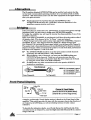
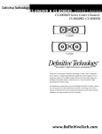
To bridge the amplifrer you will need to reverse the phase polarity of one of the
amplifier's channels.
Apply your input to CHANNEL d and channel A will then drive the positive side of
the speaker load. (This channel is the "In Phase" input and output).
A Phase Change lead is then used to strap input signal from CIIANNEL A input to
CHANNEL B input. (See diagram below for details of a Phase Change lead).
Now Channel B is receiving the input signal which is out of phase with Channel A
The speaker load is then placed between the two Red Binding Post Output terminals.
Channel A Output will be connected to the positive (+) side of the load, and Channel
B Output to the negative C) side of the load.
lIP
[F
F
The ATTENUATOR.S shouldbe set to the same postion on both channels
(preferably the OdB Attenuation - fully clockwise)
When bridgng a pair of channels, you must use the RED binding post
OUIPUTS of those channels. These two red connectors are the only
connections to be made to the speaker load. The same output can be found
by using Pin 3 from both of the XLR OUTPUTS.
Do NOT make any other connections at all to the speaker OUTPUT
terminals or connectors.
NOTE: Pin 2 on conrpchr A goes to
p{n 3 on @nrrclor B. (And
pin 3 on @nnector A goes to
pin 2 on onrcctor B).
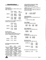
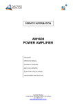
Channel A Visual Display
(foud
to the left of the power
sri@
(Channel B is a minor image of this).
A simple, yet thorough, Visual display section is found on the Front Panel of the
amplifrer. This section provides the user with the necessary day-to-day function of
an Output Level LED Ramp, as well as including various circuitry status
indicators.
k
To describe the indicators clearly, we will only discuss the teft hand side of the
unit (also known as Channel A), since the Riglrt hand side (Channel B) is a mirror
image of the left,.
Poge 4
:
a
Ihermcd lndicotion
The only indicator not duplicated is the THERMAL LED. This LED is found in
the centre of the amplifier (aboue the POWER switch). When switching the
amplifier on, the light will flash red indicating correct operation of the Mains InRush Suppression circuit. This light will not illuminate in normal use.
This LED will glow Red when the amplifier has shutdown due to excessive heat
build up - in this situation all indicators will extinguish and only the fans remain
operational on the unit. The unit will then automatically restart when the
internal temperatures return to a safe operating level.
PowerOn lndicolion
(Refer to Dingram aboue)
The LEDs closest to the mains switch glow Green when on. The
first indicates the
amplifier is oN. (It actually indicates the 15 volt preamp supply is present - the
left hand side display shows -15v, and the right hand side shows the +lbv).
The next LED outwards is also a supply indicator and also shows power on. (It
indicates that the Positive High Tension Power Supply to the output stage is
present - on the corresponding channel).
level lndicotion
Each channel features a variable 10 segment display showing actual power level
before clipping, (taking mains supply and load into account).
The display is colour coded, and calibrated in 3dB increments.
As seen in the diagram, the first of these is the -2?dB T.FID, and this is the only
one not labelled on the unit. The 10 LEDs are ; Green, -27d8 to -21d8;
Yellow, -18d8 to -6dB; Red, -3d8, and two CLIP LEDs.
Fqull lndicolion
A FAIILT LED is located above each ATTENUATOR. This LED will light orange
in the event of a short circuit on the amplifre/s Output or speaker lines. The same
LED will light orange when the Rear Panel Negative RAIL F{.ISE of the
conesponding channel has failed. (Both these conditions require signal).
Olher Foull lndicqtions
[F When a Rear Panel Positive RAIL FUSE has failed, the entire level meter
for that particular channel will light up, and the High rension Green LED
will extinguish (this is thz second Green LED in frcm the powE? switch).
lF If the Output load is to low in impedance, or the output is driven into heavy
clipping, then the FAULT LED will glow dimly with the signal.
lP If the THERMAL LED remains on after turn on, and/or pulsates brightly
with applied signal, you must switch the amplifier OFF immediately! The
amplifier Slow Start Cireuitry needs servicing.
[F
AC Mains Supply
U is the same Voltage as written on the amplifrer back panel.
is adequate for the amplifier (recommended at
15 amp 220/240 volt, 25 amp 110/120 volts).
3/ Earth is always connected.
Amplifier is kept away from water or moisture.
The amplifier Outputs are not plugged back into its Inputs.
The signal source of the amplifier Iniuts should come from the same Earth
?
i
[F
[P
[F
[P
[F
[F
[P
tu
A.dil,S.
point as the amplifier.
The amplifier should be the I"AST item in a system to be turned ON,
and the FIR.ST to be turned OFF.
When replacing the Supply RAIL FttSEs, use correctly rated fuses.
ATIENUATORs are set at -10d8 or above, forfull amplifier Output.
The Red CLIP LEDs are not on continuously, as this will greatly
reduce speaker life.
Page 5
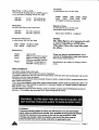
Intemodulation Distortion (IMD)
SMYIE and CCIF methnd,s
at rated output and into a 4 ohm load
Powerou@ut
with lkHz sine waue, at THD
S 0.057o,
(watts
RMS continunus)
Single Both
Load Channel Channels
AM1600 8 ohm b20 W
4?0 W
4ohm 900W 810W
2ohm 1200W 10b0W
AM1000 8 ohm 350 W
300 W
4 ohm b95W b20 W
2ohm 750W Z00W
(SMPIE methd utilises 60Hz and TkHz sine
tuoues in a 4:1 ratia)
QCIF meilnd utilises l4kfiz and.l1kHz sine
waues in o 1:1 ratia)
Output
with lkHz sine waue, at THD
bridged output,(watts RMS )
Output
Load
AM1600 8 ohm
4ohm
AM1000 g ohm
4
ohm
S 0.05Vo,
A.OlSVo (SMPTE)
0.0A77o
(CCF)
Input Sensitivity
both chanrcls driven at rated power into a 4
ohm loa.d.
+1.5dBm (0.92 volts RMS)
Input CMRR
(Cotnmon Modc Rejectinn Ratia)
Output
100H2 lkHz 10kHz 2Ok}Jz
97dB 91dB 72dB 67dB
W
2100W
1040
1400
W
W
Input Inpedance
balanced input, with lkHz sine woue
D5rnamic Power
Power output (watts nMS)
with a lkHz sinc waue at hdB for 20 qrcles,
and, then -2OdB for 480 qrcles, repeated
Output
<
<
from a
Power
1620
IMD
IMD
Power
Load Output
AM1600 4 ohm
950 W
AM1000 4 ohm
62b
8.5kO
10kO
Voltage Gain
at rated power with TkHz siw wave
AM1600 62x
AM1000 50x
W
Total Harmonic Distortion
AM1600
AM1000
(35.8d8)
(34.0d8)
Danping Factor
at rated power with TkHz sirc waue
(TIID)
AM1600
intn 8 ohm
ohm
ohm
AM1000 into g ohm
4 ohm
4
2
> 6b0:1
400:1
>
noise)
> 200:1
100H2 lkHz 20kHz
> 6b0:1
Single clwnnel at rated power output
> Bb0:1
8 ohms <0.004Vo <O.UO Vo 0.025Vo
4 ohms <0.005% <0.0047o 0.05%
Both channels with 0.5d8 ottenuotinn
at rated power with 20kHz sine waue
4 ohms <0.005Vo <0.0O4Vo O.O\1Vo
Single channel with -SdB to -10d8 attenuatinn
AIVI1600 into g ohm
> 130:1
(ond
4 ohms 0.0A4Vo 0.O04Vo 0.027Vo
Single chanrcl with -20d8 ottenuntion
4
ohms
0.0l2Vo 0.009%
0.027d%o
Single chanwl ot 1 watt output leuel
4 ohms 0.025% 0.016% 0.045Vo
tu
Poge 6
fime
(-llVo tn +90%)
measuring tlw leading edge of a 20kHz quare
waue, just before clipping, into 8 ohm toad
Rise
AM1600
AM1000
2.21ts
2.0 ps
170 volts pk-pk
138 volts pk-pk
Slew Rate
(intludes all filters) into 8 ohm lmd,
AM1600
AM1000
65 volts / psecond
60 volts /psecond
fbequencXr Response
at rated power into o 4 ohm lmd,
20Hz -2Ok}Iz (-0.5dB,-0.15d8)
(-3dB points)
5Hz - 90kHz
Crosstalk
at rated power into a 4 ohm load..
2O0Hz 500H2
lkHz 10kHz 20kHz
94dB 94dB 93dB ?5dB
(aueraged out between chonruls)
67dB
Signal to Noiee
at roted power into a 4 ohm lood,
(att e nuators fully cln k w i s e)
better than 105d8 (A - weighted)
NOTE:
The dBm figures are rtueosured with
cr sounce impedonce of 600 ohn
(Therefore thq also read the som.e
for dBu.)
Dinensions
Height
width
Depth
Weight
133mm (3U)
482mm (across front panel)
460mm including handles
(375mm excluding handles)
AM1600 is 30 kg (approx.)
AM1000 is 25 kg (approx.)
Ttrese ane factory specffications and a
variety of independent testr have ehown
them to be conseryative.
Specifications &re subject to change without
notice.
Test Conditlons
'AC Mains voltage held at 240 vofts.
'All measurements are with a 600 ohm source impedance.
"Crosstalk is measured with one channetat rated pwer, white the other has its attenuatorfully
@unterclockwise, and input lead annected.
'All distortion measurements were bandwidth timited to 30kHz, except the 20kHz measurements which
were 200kHz band limited.
'!!t9! ohm (and bridged 4 ohm) Wwer output measurements, are the outryts achieved at 0.0s% THD .
SUSTAINiNG oF THts PowER ts LtMtrED BY THE BA1K zANEL AC irryNs ctqcutr BREAKER,
AND SUPPLY RAIL FUSES.
'Alltest equipment grouMs were ttoating, using the speaker outryt's ground biNing pg as ground
reference. The amplifier was grouNed to AC mains atong with the variac.
WARNING:
Australlan Monltor wlshes to lntorm you that there are no user-servheable
parts lnslde the AM1600 and AMtooo. onty quailfled serytoe peFonnet shoutd
attempt the removal of any covers ofi the unlt, lor any purposes. Lethal
voltages are present lnslde the ampllfler, and the Ac llne cord must be
dlsconnected lrom the Ac malns ouilet prlor to openlng the unlt.
tu
Poge
7
Australian Monitor warrant the AI\{1600 and AIVI1000 amplifiers
for a period of 24 months from the date of purchase.
Warranty terms are:
rl
Warranty covers parts and labow fm a period of 24 months from first cus0omers purchase from an
authorised Ausralian Monitor dealer.
2l Warranty covers defects in material and workmanship, but does not cover damage due to misuse, atuse,
accident, or neglecL
3/ Proof of original puchase is all you need, retain your sales docket, which must be dated and show the serial
number of the uniL A copy of the sales docket should accompany the amplifier if claiming Warranty.
4l Ship the unit in its original packaging. Prepay the freight, and we will pay for the renrm freighr
ternational Warranty Terms
1/
2/
3/
4/
5/
:
Electrronic, electrical and performance Warranty covers pra & labour for a period of 24 months from
original customer purchase from an authorised Australian Monitor dealer.
Limited Chassis Warranty: The chassis is warranted for a period of five (5) years from initial purchase,
against defecs in materials and workmanship.
Such warranty does not apply where, in the opinion of your Australian Monitor Service oentre, the
amplifier has been suspended in an equipment rack without rear support
Elecronic, electrical and performance Wananty covers defects in materials anil workmanship, but does not
cover damage due to misuse, abuse, accident, or neglect.
In the event of a situation occuring that would give rise to a Waranty claim, please contact the point of
purchase to seek dvice on the best procedure.
Failing contact witlt point of purchase, please contact your national distributor, or in the event this proves
difficult" telephone Ausralian Monitor here in Ausralia.
tu
Australian Monitor Pty. Lt,C.
53 College street Gladesville NSW AUSTRALIA 2111
Phone 6L 2 816 3544 Fax 61 2 8174303
Ausballan Morftor
tu
Page
I