1
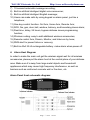
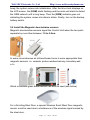
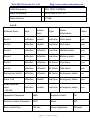
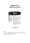
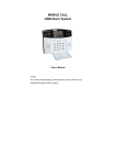
GSM LCD Alarm System
WL1014
User Manual
Date Issued: 2011-01-08
Well SEC Electronic Co., Ltd
Http://www.wellsecurityalarm.com
Thank you for purchasing this alarm system. For proper use and your
safety, please read these instructions thoroughly and carefully before you
put the system in use. Keep this manual carefully for your reference in the
future.
Warning
Do not remove the front or back cover of the unit and keep it intact.
There is no part that can be repaired by user. If repair is needed,
please send it to seller or authorized service point.
The information contained in this manual is prepared for the alarm
system only. It adopts a sustainable development strategy.
Therefore, the company retains the right to modify or make
improvement to any product described herein without giving prior
notice. All rights reserved. The name of other companies or
products referred to herein may be the brand or product name of
their respective owners.
Precautions
Please read and follow the brief instructions below, otherwise physical
danger or system damage may be incurred. This manual contains more
detailed information about safety issues concerning the system in other
parts hereof.
Page 1 of 35 Ver 2.1
Well SEC Electronic Co., Ltd
Http://www.wellsecurityalarm.com
Read this manual carefully before you
Proper use
put he system in use.
Operate in accordance with the
instructions herein.
Water-proofness
Qualified maintenance
service
The alarm system is not
waterproof. Please keep it dry.
Only those qualified maintenance
professionals may repair the
alarm system.
Be sure to back up all important
Backup
information stored in the system.
Original parts and
batteries
Only original parts and batteries
approved by manufacturer may be
used, otherwise the warranty
term may be breached and
danger may occur.
Page 2 of 35 Ver 2.1
Well SEC Electronic Co., Ltd
Http://www.wellsecurityalarm.com
Addition of other
equipment
Switch on safety
Interference
Before adding other equipment, please
read the user manual for detailed safety
instructions. Be sure not to connect
incompatible products to the system.
Do not switch the Device on when
wireless phone use is prohibited or when
it may cause interference or danger.
All wireless devices may be susceptible
to interference, which could affect
performance.
Switch off in
Follow any restrictions. Switch the device
restricted areas
off in aircraft, near medical equipment,
fuel, chemicals, or blasting areas.
Page 3 of 35 Ver 2.1
Well SEC Electronic Co., Ltd
Http://www.wellsecurityalarm.com
Table of contents
1.
2.
3.
4.
5.
6.
7.
Brief introduction ----------------------------------------------------6
Standard Packing list ----------------------------------------------6
Function Introduction ----------------------------------------------6
Alarm Host Diagram -----------------------------------------------7
Installation ------------------------------------------------------------9
5.1 Insert SIM into Control Unit----------------------------------9
5.2 Install the Magnetic door/window sensors---------------10
5.3 Install the wireless PIR Motion Sensor-------------------11
5.4 Install other sensors------------------------------------------12
5.5 Install the Control Unit----------------------------------------12
5.6 Siren and wireless outdoor siren--------------------------12
Setting-----------------------------------------------------------------13
6.1 Enter Settings-------------------------------------------------13
6.2 Exit Settings---------------------------------------------------14
6.3 Factory Reset-------------------------------------------------14
6.4 Remote controller--------------------------------------------14
6.5 Defense zone-------------------------------------------------15
6.6 Change pass ward-------------------------------------------16
6.7 Clock Setting--------------------------------------------------17
6.8 Timing Settings-----------------------------------------------18
6.9 Call alert target phone number---------------------------19
6.10 SMS Alert Target cell phone number-----------------20
6.11 Defense Zone Programming----------------------------21
6.12 Home Arm Defense Zone Setting----------------------22
6.13 Voice Recording--------------------------------------------22
6.14 Siren Setting-------------------------------------------------23
6.15 Siren Setting in “Emergency Help” mode------------23
Operation Instructions --------------------------------------------23
7.1 Remote Controller Operation-------------------------------24
7.2 Answer Alarm Call--------------------------------------------26
7.3 Remote Control------------------------------------------------26
Page 4 of 35 Ver 2.1
Well SEC Electronic Co., Ltd
8.
9.
10.
11.
12.
13.
14.
Http://www.wellsecurityalarm.com
7.4 System Dialing Function-------------------------------------27
Technical Parameters---------------------------------------------28
Care--------------------------------------------------------------------30
Add/Cancel wireless sensors to the Control Unit-----------31
Technical specifications of Control Unit-----------------------32
Important information----------------------------------------------32
Maintenance --------------------------------------------------------33
Warranty--------------------------------------------------------------33
Page 5 of 35 Ver 2.1
Well SEC Electronic Co., Ltd
Http://www.wellsecurityalarm.com
1. Brief introduction
The WL1014 is an innovative safety solution for home, office and industry.
It integrates GSM network, SMS Control, voice, wireless communication
and proprietary technologies. It is suitable for a wide range of applications.
2. Contents
Standard Packing List:
Control Unit
Magnetic Door Sensor
Two Wireless Remote Controls
PIR Motion Sensor
Mini Siren
Regulated 12vDC Power Supply
User Manual
Optional Accessories:
Combined Light and Siren
PIR Motion Sensor
Glass Break Sensor
Magnetic Window Sensor
Magnetic Steel Scrolling Door Sensor
Temperature Sensor
Oil Pressure electronic Sensor
Infrared Beam Fence
3.
1)
2)
3)
4)
5)
Function Instruction
7 wired and 99 wireless defense zones;
LCD screen with time clock display;
Voice prompt for all operations;
3 groups of timely arm and disarm;
Can store 6 phone numbers: when alarming, system will make alarm
call to these numbers automatically;
6) Can store 3 SMS numbers: when alarming, system will send alarming
SMS automatically;
Page 6 of 35 Ver 2.1
Well SEC Electronic Co., Ltd
Http://www.wellsecurityalarm.com
7) 10-second automatic message recording;
8) Built-in artificial intelligent digital voice announcer;
9) Built-in artificial intelligent English message;
10) Users can make calls by using keypad on alarm panel, just ike a
telephone;
11) One-key-control function: Out Arm, Home Arm, Remote Arm;
12) SOS, fire, gas, door, hall, window, balcony, and boundary places alarm;
13) Real-time, delay, 24 hours, bypass defense zones programming
function;
14) Wireless coding: easy to add additional wireless accessories;
15) Remote control Arm, Disarm, Monitor, and Intercom by hone;
16) SMS alert for power failure or recovery;
17) Built-in AAA NI-HI rechargeable battery: make alarm when power off.
4. Alarm Host Diagram
In order to make the main unit get the wireless signal well for all wireless
accessories, please put the alarm host at the central place of your defense
area. Make sure it’s away from large metal objects and household
appliances which may cause high frequency interference, as well as
barriers such as reinforced concrete wall or fire door, etc.
Alarm Panel front schematic diagram:
Page 7 of 35 Ver 2.1
Well SEC Electronic Co., Ltd
Http://www.wellsecurityalarm.com
Alarm Panel back schematic diagram:
Wired terminal block:
LCD display:
Page 8 of 35 Ver 2.1
Well SEC Electronic Co., Ltd
Http://www.wellsecurityalarm.com
5. Installation
5.1 Insert SIM into Control Unit
Please see the below photos:
Please insert SIM card and plug in power adaptor, and then power on the
system, all the LED lights will be on for 2 seconds and you will hear a long
Page 9 of 35 Ver 2.1
Well SEC Electronic Co., Ltd
Http://www.wellsecurityalarm.com
beep; the system comes into initialization. After the time clock displays on
the LCD screen, the [SGM] starts flashing and the main unit starts to detect
the GSM network until a long beep. Then the [SGM] indicator goes out
indicating the system comes into disarm status. Finally, turn on the backup
battery switch.
5.2 Install the Magnetic door/window sensors
Magnetic door/window sensors signal the Control Unit when the two parts
separate by more than between 1.5 to 3.0cm.
In some circumstances an Infrared beam fence is more appropriate than
magnetic sensors. i.e. veranda, picture window balcony, boundary wall
e.t.c.
Wired or wireless glass break sensor can also be used (see below)
For a Scrolling Steel Door, a special Wireless Scroll Steel Door magnetic
sensor, must be used due to interference of the wireless signal caused by
the steel door.
Page 10 of 35 Ver 2.1
Well SEC Electronic Co., Ltd
Http://www.wellsecurityalarm.com
Installation: attach the larger half to the floor and attach (rivet or glue) the
smaller half to the scroll steel door. An alarm is triggered when the halves
are separated by more than three to 5.00 cm.
Scroll Steel Door
5.3 Install the wireless PIR Motion Sensor
The PIR sensor will detect a person since human temperature is different to
ambient temperature. When triggered, the PIR will signal the Control Unit.
Apply the detection area illustration below when installing.
Wireless curtain sensor, detection area illustration below:
Page 11 of 35 Ver 2.1
Well SEC Electronic Co., Ltd
Http://www.wellsecurityalarm.com
5.4 Install other sensors
For smoke, you can use wireless smoke sensor, for gas leakage detection,
you can install gas leakage sensor below
For temperature, you can install the temperature sensor below:
5.5 Install the Control Unit
In order to avoid destruction of the Control Unit by intruders, please install it
in a concealed location, convenient to the operator.
If applicable, ensure that an uninterruptible AC power outlet is available
near the Control Unit. First connect accessories to the Control Unit then the
AC adapter.
5.6 Siren and wireless outdoor siren
Connect the Siren and the intercom to the Control Unit and fix them in
appropriate locations .
1)Mini Siren
Page 12 of 35 Ver 2.1
Well SEC Electronic Co., Ltd
Http://www.wellsecurityalarm.com
2) Wired strobe siren
3) wireless outdoor siren
Wiring Diagram of Outdoor siren for WL1014
6. Settings
6.1 Enter Settings
In the state of disarm, input 4-digit password by the keypad on the main
unit and press [#] button to confirm. You will hear a voice prompt: please
enter instruction. At the same time, [SET] indicator is on without flashing
and [0000] displays on the screen, indicating the system enters setting
status. You can perform different settings repeatedly as long as the system
keeps in setting status. The system will exit setting mode and return to
disarm status if you don’t press any keypad button for 40 seconds.
can delete the numbers input.
Note: In setting status, press
The system default password is [8888].
Operating method: [XXXX]➩[#]
X indicates the new 4-digit password.
LCD display:
Page 13 of 35 Ver 2.1
Well SEC Electronic Co., Ltd
Http://www.wellsecurityalarm.com
6.2 Exit Settings
Press [*] and [#] buttons, the main unit emits a long beep and exits
settings. The [SET] indicator goes out and the system returns to disarm
state.
Operating method: 【*】➩【#】
6.3 Factory Reset
In disarm status, use keypad to input [95175308246] and press [#] to
confirm, all the LED indicators will be on for 2 seconds and you will hear a
long beep. The main unit gets all its settings cleared and restores to its
factory settings successfully.
Operating method: [95175308246] + [#]
6.4 Remote controller
6.4.1 Coding of Remote Controller
The remote controller has to be code to the alarm host in order to
perform normally.
In setup state, use keypad to input [20], input the remote controller number
[1~8], and then press [#] to confirm. The main unit emits a long beep and
you will hear “remote control coding”. The [
] indicator is on without
flashing; press any button on the wireless remote controller, the main unit
makes a long beep and you will hear “coding completed”,[
] indicator
goes out, indicating the remote controller succeeds in coding.
Operating method: [20]➩[A]➩[#]
A indicates: 1~8 remote controllers number. You can add maximum 8
Page 14 of 35 Ver 2.1
Well SEC Electronic Co., Ltd
Http://www.wellsecurityalarm.com
remote controllers.
LCD display:
4
6.4.2 Delete Remote Controller
The remote controller can’t control the main unit after it’s deleted.
In setup state, use keypad to input [21], then input the remote controller
number [1-8], and then press [#] to confirm. The main unit emits a long
beep and the [Signal] indicator flickers once. You will hear a voice
prompt “delete completed”.
Operating method: [21]➩[A]➩[#]
A indicates: 1~8 remote controllers number.
6.5 Defense zone
6.5.1 Coding of defense zone
Wireless detectors have to be coded to the main unit in order to trigger it
alarms.
In setup state, use keypad to input [23], input the defense zone number you
want to code [01~99], and then input [#] to confirm. The main unit emits a
long beep and the corresponding defense zone is displayed on the screen.
You will hear a voice prompt “detector coding”. Then trigger a wireless
detector to emit a wireless signal; after receiving the signal, the main unit
makes a long beep, and you will hear “coding completed”, the [
indicator goes out at the same time.
Operating method: [23]➩[XX]➩[#]
XX indicates: 01 ~99 defense zones number
LCD display:
Page 15 of 35 Ver 2.1
]
Well SEC Electronic Co., Ltd
Http://www.wellsecurityalarm.com
6.5.2 Delete Defense Zone
The wireless detector can’t control the main unit after it’s deleted.
In setup state, use keypad to input [24], then input the defense zone
number you want to delete [01~99], and then input [#] to confirm. The main
unit emits a long beep and the defense zone indicator flickers once. You
will hear a voice prompt “delete completed”.
Operating method: [24]➩[XX]➩[#]
XX indicates: 01 ~99 defense zones number
6.6 Change passward
6.6.1 Change Operation Password
Operation password is the password used to disarm or remote control.
In setup status, use keypad to input [30], then input the 4-digit new
password, and then press [#] to confirm. The main unit will make a long
beep and you will hear a voice prompt “setting completed”.
Operating method: [30]➩[XXXX]➩[#]
XXXX indicates: the new 4-digit password
For example: change the system password to 1012
Operating method: [30]➩[1012]➩[#]
LCD display:
6.6.1 Change Program Password
Program password is the password you should input in order to setup the
system.
Page 16 of 35 Ver 2.1
Well SEC Electronic Co., Ltd
Http://www.wellsecurityalarm.com
In setup status, use keypad to input [31], then input the 4-digit new
password, and then press [#] to confirm. The main unit will make a long
beep and you will hear a voice prompt “setting completed”.
Operating method: [31]➩[XXXX]➩[#]
XXXX indicates: the new 4-digit password
For example: change the system password to 2846
Operating method: [31]➩[2846]➩[#]
LCD display:
Note:the operation password and the programming password can not
be set as the same number.
6.7 Clock Setting
In setup status, use keypad to input [32], then input the last 2 digits [AA] of
the present year, the two digits [BB] of the month, the two digits [CC] of the
date, the two digits [DD] of the hour (24-hour system), the two digits [EE] of
the minute, the two digits [FF] of the second, and finally enter [#] to confirm.
You will hear a long beep and a voice prompt “setting completed”.
Operating method: [32]➩[AA]➩[BB]➩[CC]➩[DD]➩[EE]➩[FF]➩[#]
AA indicates: the last 2 digits of the present year
BB indicates: the 2 digits of the present month
CC indicates: the 2 digits of the present date
DD indicates: the 2 digits of the present hour
EE indicates: the 2 digits of the present minute
FF indicates: the 2 digits of the present second
For example: set the time as 15:35:40, Oct. 1st, 2009
Operating method: [32]➩[09]➩[10]➩[01]➩[15]➩[35]➩[40]➩[#]
Page 17 of 35 Ver 2.1
Well SEC Electronic Co., Ltd
Http://www.wellsecurityalarm.com
6.8 Timing Settings
6.8.1 Timely Arm
In setup status, use keypad to input [33~35], then input the hour [AA] and
minute [BB] of the time you want to set to arm, and finally input [#] to
confirm. You will hear a long beep and a voice prompt “setting completed”.
Operating method: [XX]➩[AA]➩[BB]➩[#]
XX indicates: the address code 33, 34, 35 of the timely arming
AA indicates: the hour of the setting time
BB indicates: the minute of the setting time
For example: set the arm time as 45’ 10pm
Operating method: [33]➩[22]➩[45]➩[#]
LCD display:
6.8.2 Timely Disarm
In setup status, use keypad to input [36~38], then input the hour [AA] and
minute [BB] of the time you want to set to disarm, and finally input [#] to
confirm. You will hear a long beep and a voice prompt “setting completed”.
Operating method: [XX]➩[AA]➩[BB]➩[#]
XX indicates: the address code 36, 37, 38 of the timely disarming
AA indicates: the hour of the setting time
BB indicates: the minute of the setting time
For example: set the arm time as 55’ 7am
Operating method: [33]➩[22]➩[45]➩[#]
LCD display:
Page 18 of 35 Ver 2.1
Well SEC Electronic Co., Ltd
Http://www.wellsecurityalarm.com
6.8.3 Timing Control
In setup status, use keypad to input [39], then input the number indicating
turning on timely arm/ disarm [1/0], and then input [#] to confirm. You will
hear a long beep and a voice prompt “setting completed”. The factory
default is off.
Operating method: [39]➩[0/1]➩[#]
0: turn off the function of timely arm/ disarm
1: turn on the function of timely arm/ disarm
For example: turn on the function of timely arm/ disarm
Operating method: [39]➩[1]➩[#]
6.9 Call alert target phone number
6.9.1 Set alert target phone number
In setup state, input [51] ~ [56], then input the voice alarm-receiving
number (mobile number or telephone number), and then press [#] to
confirm. The main unit will make a long beep, the [Signal] indicator will
flicker once, and you will hear “setting completed”, which indicate voice
alarm-receiving number is set successfully.
Operating method: [XX]➩[YY…YY]➩[#]
XX indicates: the 1- 6 alarming user number [51] ~ [56]
YY…YY indicates: voice alarm-receiving phone number
For example: set 13811111111 as the first voice call number
Operating method: [51]➩[13811111111]➩[#]
LCD display:
Page 19 of 35 Ver 2.1
Well SEC Electronic Co., Ltd
Http://www.wellsecurityalarm.com
6.9.2 Delete alert target phone number
In setup state, input [51] ~ [56], and then press [#] to confirm, the main unit
will make a long beep and the [Signal] indicator will flicker once and you
will hear “delete completed”, which indicate the alarming user number is
deleted successfully.
Operating method: [XX]➩[#]
XX indicates: the 1- 6 alarming user number [51] ~ [56]
For example: Delete the third alarming user number from the system.
Operating method: [53]➩[#]
LCD display:
6.10 SMS Alert Target cell phone number
6.10.1 To set SMS Alert Target cell phone number
SMS Receiving number means when system is alarming, it will only send
SMS to this mobile number. You can set maximum 3 SMS numbers. In
setup state, input [57] ~ [59], then input the SMS receiving number, and
then press [#] button to confirm. The main unit will make a beep, the
[Signal] indicator will flicker once and you will hear “setting completed”,
which indicate setup successfully.
Operating method: [XX]➩[YY…YY]➩[#]
XX indicates: address codes of message-receiving numbers from the
first group to the third group [57] ~ [59]
YY…YY indicates: the SMS receiving number
For example: setup 13822222222 as the first SMS receiving number
Page 20 of 35 Ver 2.1
Well SEC Electronic Co., Ltd
Http://www.wellsecurityalarm.com
Operating method: [57]➩[138222222]➩[#]
6.10.1 Delete SMS Alert Target cell phone number
In setup state, use keypad to input [57] ~ [59], and then press [#] button to
confirm. The main unit will make a beep, the [Signal] indicator will flicker
once and you will hear “delete completed”, which indicate SMS number is
deleted successfully.
Operating method: [XX]➩[#]
XX indicates: address codes of message-receiving numbers from the
first group to the third group [57] ~ [59]
For example: delete the first SMS user number from the system
Operating method: [57]➩[#]
6.11 Defense Zone Programming
If you want to change the alarm attribute of defense zone, such as turn off
the siren when system alarms, you can do it by defense zone programming.
In setup state, first input [60], then the defense zone number [01~99], then
input defense zone type [1~4], then input defense zone location number
[1~8], and then select siren on/off [0/1], at last press [#] to confirm. You will
hear the main unit emit a long beep and a voice prompt “setting
completed”.
Operating method: [60]➩[AA]➩[B]➩[C]➩[D]➩[#]
AA: defense zone number [01~99] means zone 1 to zone 99;
B: defense zone type
[1]: real-time defense zone [2]: 40 seconds delay defense zone
[3]: 24 hours defense zone [4]: bypass defense zone
C: defense zone location
[1] SOS Alarm
[2] Fire Alarm
[3] Gas Leak Alarm
[4] Door Alarm
[5] Hall Alarm
[6] Window Alarm
[7] Balcony Alarm [8] Boundary Alarm
D: siren ON/OFF: [0] OFF, [1] ON
Page 21 of 35 Ver 2.1
Well SEC Electronic Co., Ltd
Http://www.wellsecurityalarm.com
For example: set defense zone 12 to be 24-hour, fire alarm and siren on
Operating method: [60]➩[12]➩[3]➩[2]➩[1]➩[#]
6.12 Home Arm Defense Zone Setting
If you want some detectors work and some do not, you can use [Home
Arm] function.
In setup state, use keypad to input [61], then choose the corresponding
defense zone number [01~99], then choose [Home Arm], and then choose
whether alarm [0/1] button, and finally press [#] to confirm. The main unit
will make a long beep and a voice prompt “setting completed”.
Operating method: [61]➩[XX]➩[A]➩[#]
XX indicates: [01~99] is defense zone 1 to defense zone 99
A indicates: [0] Home arm but not alarm
[1] Home arm and alarm
For example: set defense zone 11 to be Home arm and alarm
Operating method: [61]➩[11]➩[1]➩[#]
For example: set defense zone 12 as Home arm but not alarm
Operating method: [61]➩[12]➩[0]➩[#]
6.13 Voice Recording
In setup state, use keypad to input [701], and then press [#] to confirm.The
main unit will emit a beep and the [
] indicator is on, and after 10
seconds countdown, recording starts: record at 30cm away from the main
unit with moderate tone; 10 seconds later, the main unit will make a beep
indicating the recording stops and the recorded voice will replay.
Operating method: [701]➩[#]
LCD display:
Page 22 of 35 Ver 2.1
Well SEC Electronic Co., Ltd
Http://www.wellsecurityalarm.com
6.14 Siren Setting
In setup state, use keypad to input [75]; in the operation of arm/ disarm
by remote control, select if the siren sounds or not by [0/1] button, and
then press [#] to confirm. The main unit will emit a long beep and a
voice prompt “setting completed”.
Operating method: [75]➩[A]➩[#]
A indicates: [0] Siren off; [1] Siren on; System default: [0] Siren off
For example: set siren on when arm/ disarm
Operating method: [75]➩[1]➩[#]
LCD display:
1
6.15 Siren Setting in “Emergency Help” mode
In setup state, use keypad to input [76], and then [1/0], finally press [#] to
confirm. The main unit will make a long beep and a voice prompt “setting
completed”.
Operating method: [76]➩[A]➩[#]
A indicates: [0]: siren off in “Emergency Help” mode
[1]: siren on in “Emergency Help” mode
System default: [0] siren off
7. Operation Instructions
Page 23 of 35 Ver 2.1
Well SEC Electronic Co., Ltd
Http://www.wellsecurityalarm.com
System status. There are 4 status as following:
1) Arm: defense zone 1~99 will alarm when detectors are triggered
2) Home Arm: in arm status, the defense zone which is set as [Home Arm]
will alarm when detectors are triggered.
3) Disarm: defense zone 1~99 will not alarm when detector triggered
(except 24 hours defense zone)
4) System setup status: In this status, all defense zones will not alarm when
detectors are triggered.
7.1 Remote Controller Operation
Users can use remote controller to set system as Out Arm, Home Arm,
Emergency Alarm, Real-time Disarm and etc.
1) Out Arm: Press
2) Disarm: Press
3) Home Arm: Press
button
button
button
4) Emergency Alarm: Press
button, system will alarm at once.
Operation:
7.1.1 Out Arm
It means to guard all around your house while everyone is going out; all the
detectors of the host are always working; when the detector is triggered by
detecting source (anti-theft, fire prevention, gas leak, etc.), the alarm
system will sound the alarm.
Press [Out Home
] button on keypad, system will make a beep per
second and totally 100 beeps. The [OUT ARM] indicator will be on without
flashing. It means Out Arm is set successfully.
Arm Operation: Press [Out Home
] button, the system will enter arm
status 100 seconds later.
LCD display:
Page 24 of 35 Ver 2.1
Well SEC Electronic Co., Ltd
Http://www.wellsecurityalarm.com
7.1.2 Disarm
It means to stop the alarm when the main unit sounds the alarm or make
the alarm system in the state of non-warning. After disarming, even if you
trigger the detector, the main unit would not sound alarm (excluding
24-hour defense areas).
Use keypad to input system password, then press [#] button. [Out Home]
or [At Home] lights will be off. It means disarm setting successful.
Remote Control Operation: Press [
] button on remote controller
Main Unit Operation: input system password + [#]
LCD display:
7.1.3 Home Arm
It means, for the safety, while somebody is at home, you need to enable
the peripheral door, window, balcony and boundary detectors of the alarm
system while prevent from triggering the indoor detectors, which may
cause improper warning; then, you shall select Arm at Home, let just part of
the detectors work and disable the other parts.
Main Unit Operation: Press [At Home
Remote Control Operation: Press [
] button on keypad
] button on remote controller
LCD display:
Page 25 of 35 Ver 2.1
Well SEC Electronic Co., Ltd
Http://www.wellsecurityalarm.com
7.1.4 Emergency Help
Press [Emergency
] button on keypad, or [
] button on remote
controller or wireless panic button, the main unit will alarm and make call to
the preset user numbers.
7.2 Answer Alarm Call
When the main unit sounds alarm, it will dial the preset numbers. If no one
answers the call, the system will call the next user number automatically.
The system will call each preset numbers for 3 times in order.
If you answer the call, you will hear the pre-record voice. You can set
system via your telephone or mobile phone keypad.
If you hang-up directly without answering the call, the system will call each
preset number for 3 times circularly.
Press [*]: Read the alarm information.
Press [1]: Main unit stops alarming and Arm; it stops calling users.
Press [2]: Main unit stops alarming and Disarm; it stops calling users.
Press [3]: Siren off and monitors the scene for 30 seconds; for continued
monitoring, press [3] again to monitor for another 30 seconds.
Press [4]: Main unit starts a 30-second two-way intercom. It cannot be
controlled by the mobile during the time of intercom.
7.3 Remote Control
Dial the number associated to the alarm main unit by phone (mobile phone),
and after one ringing cycle, you can hear a voice prompt “Please enter
password”. If the password is right, you will here “Press 1 to arm, Press 2 to
disarm, Press 3 to Monitor, Press 4 to Intercom”. If the password is wrong,
you will hear a prompt voice “wrong password, please re-enter”.
Press [1]: arm, if finished successfully, you will hear a voice prompt
“System armed”.
Page 26 of 35 Ver 2.1
Well SEC Electronic Co., Ltd
Http://www.wellsecurityalarm.com
Press [2]: disarm, if finished successfully, you will hear a voice
prompt “System disarmed”.
Press [3]: monitoring for 30 seconds, to continue monitoring, press
[3] again to monitor for another 30 seconds.
Press [4]: two-way intercom for 30 seconds. You can’t operate the
main unit during this time.
7.4 System Dialing Function
In disarm status, you can use the main unit to make any call just like a
land-line telephone. Dial telephone number on keypad, press [
] button,
the main unit will make a beep and the [Signal] indicator will be flashing.
] button again, the main unit will be in disarm
After the call, press [
status.
Alarming Record Checking
In disarm state, input [*0#], then the main unit will make a long beep and
enters the state of alarm record checking. After displaying the alarm and
defense zone number indicator, the LCD screen will display the exact
alarming time of this defense zone. Press 2, you can upturn to check the
previous alarming record; press 8, downturn to check; and press [*#] to exit
checking.
For example: the 51st defense zone; the 7th alarming; alarming time:
12:10, August 1st, 2008. LCD display for one second, and then display
the alarming time:
15
and then display the alarming time:
Page 27 of 35 Ver 2.1
Well SEC Electronic Co., Ltd
Http://www.wellsecurityalarm.com
GSM Signal Checking
Before installing the main unit, you should check the signal of the installing
place in order to ensure the unit can perform well. In setup state, input [81]
➩#, the main unit will make a long beep and display 00+XX (XX indicates
the intensity of the signal). And the intensity should be within the range of
07-31; if it’s less than 07, you should change place.
For example: if the signal intensity is 12, it will display as:
Note:
Only under Out Arm status, the system has the function of sending SMS
alert for power failure/ power recovery. While in Disarm or Home Arm
status, it does not.
The SMS content:
Power failure: Power changer off
Power recovery: Power changer on
8. Technical Parameters
List 1:
Input Voltage
DC12V/1A
Standby Current
<55mA
Alarming Current
<450mA
Wireless Frequency
315/433MHz, PT2262/EV1527, 4.7MΩ
Page 28 of 35 Ver 2.1
Well SEC Electronic Co., Ltd
Http://www.wellsecurityalarm.com
GSM Frequency
900/ 1800/ 1900MHz
Back-up Battery
NI-HI AAA*6 DC7.2V
Siren Volume
110dB
List 2:
Defense Zone
Arm
Home
Arm
Type
Alarm
Information
Siren
Zone 1
effective
invalid
real-time
Door alarm
yes
Zone 2
effective
invalid
real-time
Hall alarm
yes
Zone 3
effective
effective
real-time
Window alarm
yes
Zone 4
effective
effective
real-time
Balcony alarm
yes
Zone 5
effective
effective
24 hours
Fire alarm
yes
Zone 6
effective
effective
24 hours
Gas alarm
yes
Emergency button
effective
effective
24 hours
Emergency alarm
no
Zone 7-99
effective
invalid
real-time
Emergency alarm
yes
Wired defense
zone
(96-99)
effective
invalid
real-time
Emergency alarm
yes
Operation Password
8888
Remote control
On
Remote control Password
1234
Siren
Off
Siren sound time
180 sec.
Home Appliance
Optional
Page 29 of 35 Ver 2.1
Well SEC Electronic Co., Ltd
Http://www.wellsecurityalarm.com
9. Care
The alarm system has excellent design and uses advanced technologies. It
shall be used with care. The following suggestions are required to maintain
your obligations under the warranty terms, and for prolonging the service
life of the system.
1) Place the control panel and all parts and accessories out of
children’s reach.
2) Keep the alarm system dry. Rain, humidity and various fluids or
moisture all will corrupt the electronic circuit.
3) Do not use or place the alarm system in dirty locations, otherwise
the electronic elements will be damaged.
4) Do no place the system in excessively hot locations. High temperature
will shorten the service life of electronic equipment, damage batteries,
deform or even melt some plastic parts.
5) Do not place the system in excessively cold locations. Otherwise
condensation many occur and damage the circuit board of the alarm
system.
6) It is recommended that you check and test the alarm system
periodically:
Check the main unit every three months:
1) Whether it can arm/disarm normally;
2) Whether it can dial the number for alarm normally;
3) Whether it can receive wireless detectors’ signal normally;
4) Whether the back-up battery can work normally.
Check the wireless detectors once a month:
1) Trigger wireless detectors to see if system can alarm normally;
2) Check all detectors’ batteries to see if it’s in low voltage;
3) Check whether wireless detectors can send signal to the main unit
normally.
Check the SIM card:
1) Check the use of SIM card, such as network signal, balance, etc.
Page 30 of 35 Ver 2.1
Well SEC Electronic Co., Ltd
Http://www.wellsecurityalarm.com
2) Make sure the PIN code verification of the SIM card is closed.
3) Please keep the password and SIM card number safe, in case that other
people remote control the system illegally.
a. Since the alarm system is continuously in operation or standby mode,
the supply adaptor of the control panel shall be connected to a safe and
reliable socket.
b. Do not place the system near your bedroom or office table, because the
siren will make high-loudness sound in the case of alarm, which may
adversely affect your rest or work.
c. If the alarm system will not be used for a long time, please disconnect
the system from the power supply.
d. Please do not disassemble, repair or alter the products without
permission, or it may cause accidents and faults.
e. Do not drop this product on the ground or on hard objects, as it may
lead to massive impact to cause faults and damages.
f. Without approval and consent of relevant authorities, please do not set
“110”, “119” or the alarm phone number of police station for this main
unit.
Please read the suggestions above carefully and follow the instructions
herein. If any of the equipment does not work properly, please send it to the
dealer or authorized service point for repair. We will try our best to solve the
problem for you as soon aspossible.
10. Add/Cancel wireless sensors to the Control Unit
Wireless sensors are pre-coded prior to shipping. Add additional wireless
sensors as below:
1) Open the back cover of the Wireless sensor carefully;
2) Locate the IC boards black jumpers, labelled A0-A7 and D0-D3.
3)
4)
The A0-A7 , 3X8 PIN connectors,are the Wireless Address bits code
area, and the D0-D3 are 3X4 PIN connectors, are Wireless data bits
code area;
Also, you can see the H, N, and L letters besides the 3X8 PIN and 3X4
PIN connectors, like below;
Page 31 of 35 Ver 2.1
Well SEC Electronic Co., Ltd
Http://www.wellsecurityalarm.com
5)
Connect L and N is means 0, and connect H and N is means 1,
connect neither L and N nor H and N is means 2 ;
6) According to below table, select the Zone and set the 3X4 PIN
Wireless data bits code area according to selected zone.
7) Make sure the jumpers are correct. Then install the cover carefully.
8) Turn off the sensors’ power before setting .
9) Trigger the wireless sensor and test the setting result. If the wireless
sensors do not work, please check the jumpers again.
10) You can set many sensors in the same zone.
Example: If the Control Unit ID is 02102101 at the label (that is to say, the
A0-A7 is 10120120), and you want to set all wireless PIR sensor in the
zone 3(the D0-D3 is 0101), then you can set the jumper like below:
11. Technical specifications of Control Unit
Power requirements: DC 12V
Operating temperature: –20
0
c to 60 0 c
Humidity: 20 % to 95%
Dimension: 180 x 130 x 32 mm
GSM network frequency: 900/1800/1900 MHz
Work Frequency: 315MHz±0.5MHz or 433±0.5MHz
12. Important information
12.1 Please read the User Manual carefully before you install the
Control Unit and set the Control Unit.
12.2 Do not install the system in close vicinity with objects that generate
strong interference, such as TV set and computer.
Page 32 of 35 Ver 2.1
Well SEC Electronic Co., Ltd
Http://www.wellsecurityalarm.com
12.3 Install the system in a hidden place.
12.4 Avoid getting water into the Control Unit.
12.5 Have a secure connection to the main power supply and provide
good ventilation..
12.6 This product was designed for the indoor use.
12.7 Opening the control unit cover will void the warranty.
13. Maintenance
13.1 In case of failure, please contact the distributor or manufacturer.
13.2 If the Control Unit works, while the remote controllers and other
sensors fail, please check and change the battery.
13.3 If the remote controller works, but the ,Control Unit fails to telephone
or send SMS texts, switch the power of Control Unit off and switch it
on after one minute . Test this system after another minute, or check
the settings are correct and the GSM Signals are strong enough.
13.4 If the Control Unit can run and sensors work, but cannot send SMS
texts or dial telephones, please change SIM Card to check it.
13.5 If the problem cannot be solved, please contact the distributor or
manufacturer.
14. Warranty
14.1 This system is warranted to be free of defects in material and
workmanship for one year from the date of purchase.
14.2 This warranty does not extend to any defect, malfunction or failure
caused by abuse or misuse by the Operating Instructions. In no event shall
the manufacturer be liable for any alarm system altered by purchasers.
The End!
Thanks for you use our GSM Alarm System
Any questions please contact us feel free!
Page 33 of 35 Ver 2.1
Well SEC Electronic Co., Ltd
Http://www.wellsecurityalarm.com
Warranty Card
Model ______________
Product ID ___________
Date of Purchase__________________
Date of Production___________________
Maintenance Record
__________________________________________________
__________________________________________________
__________________________________________________
Dealer _____________________________
Page 34 of 35 Ver 2.1