1
Published Manual Number/ECN: ME7C4E11AE/2002502N
• Publishing System: TPAS
• Access date: 12/13/2002
• Document ECN's: Latest Available
Schematic/Electrical Parts—
30015 and 30022C4E
Coin Operated Washer
PELLERIN MILNOR CORPORATION
POST OFFICE BOX 400, KENNER, LOUISIANA 70063-0400, U.S.A.
Please Read
About the Manual Identifying Information on the Cover
The front cover displays pertinent identifying information for this manual. Most important, are
the published manual number (part number) /ECN (date code). Generally, when a replacement
manual is furnished, it will have the same published manual number, but the latest available ECN.
This provides the user with the latest information applicable to his machine. Similarly all
documents comprising the manual will be the latest available as of the date the manual was
printed, even though older ECN dates for those documents may be listed in the table of
contents.
When communicating with the Milnor factory regarding this manual, please also provide the
other identifying information shown on the cover, including the publishing system, access date,
and whether the document ECN’s are the latest available or exact.
References to Yellow Troubleshooting Pages
This manual may contain references to “yellow pages.” Although the pages containing
troubleshooting procedures are no longer printed on yellow paper, troubleshooting instructions, if
any, will be contained in the easily located “Troubleshooting” chapter or section. See the table of
contents.
Trademarks of Pellerin Milnor Corporation
The following, some of which may be used in this manual, are trademarks of Pellerin Milnor
Corporation:
Ampsaver®
Autolint®
Auto-Purge®
Autovac
CBW®
Dye-Extractor®
Dyextractor®
E-P Express®
E-P OneTouch®
E-P Plus®
Gear Guardian®
Hands-Off®
Hydro-Cushion®
Mildata®
Milnet®
Milnor®
Miltrac
Miltron
Comments and Suggestions
Help us to improve this manual by sending your comments to:
Pellerin Milnor Corporation
Attn: Technical Publications
P. O. Box 400
Kenner, LA 70063-0400
Fax: (504) 469-1849
Staph-Guard®
System 4®
System 7®
Totaltrol®
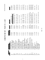
Table of Contents
for ME7C4E11AE/2002502N
30015 and 30022C4E Coin Operated Washer
Page
Description
Document/ECN
1
3
4
6
16
17
18
20
22
24
26
28
30
32
34
Component Parts List
Warranty
How to Order Parts
How to Use Electrical Schematics
3 Phase Motor Connection Diagram
3P Motor Diagram-Multivolt
Control Box Layouts
Board to Board Wiring
Flushing Supplies
Electric Valves
Microprocessor Inputs
Control Circuit Transformers
Start Circuit and Door Interlock
Variable Speed Inverter (30022 1 Phase)
Variable Speed Inverter (30015 1Phase & 30015,30022
3 Phase)
W7C4EPL/2002474N
BMP720097/92732A
BMP720097R/72332A
MSFD0106AE/95041V
BMP850029/99362B
W80008/2001253A
W7C4ETG/2002474B
W7C4EBW/2002502B
W7C4ECF/2002474B
W7C4EEV/2002474B
W7C4EIA/2002474B
W7C4ELV/2002474B
W7C4ES+/2002502B
W7C4EVPA/2002502B
W7C4EVPB/2002502B
1
COMPONENT
DETAIL-CONTROL PANEL
DETAIL-INCOMING POWER BOX
>>PRINTED CIRCUIT BOARDS
BOARD-MICROPROCESSOR
BOARD-SWITCHPANEL
>>RELAY-PILOT OR CONTROL
RELAY-DOOR NOT LOCKED
RELAY-DOOR CLOSED
>>CONTACTOR-MOTOR STARTER
CONTACTOR-ENABLE INVERTER
>>CLUTCHES-ELECTRICAL
CLUTCH-BRAKE CLUTCH
>>FUSE OR FUSE HOLDER
FUSE-CONTROL CIRCUIT X-BUS
FUSE-CONTROL CIRCUIT Y-BUS
>>ELECTROMAGNET AND SOLENOID
SOLENOID-DOOR LOCK
>>POWER SUPPLY-ELECTRONIC
POWER SUPPLY-MICROPROCESSOR
>>TRANSFORMERS
TRANSFORMER-CLUTCH 120V TO 16V
TRANSFORMER-INCOMING VOLT.240VAC
TRANSFORMER-208VAC TO 240VAC
TRANSFORMER-380/480 V TO 240
TRANSFORMER-600V
>>MOTORS
MOTOR-BASKET DRIVE
>>>INVERTERS
INVERTER--BASKET DRIVE
>>SWITCH-KEYLOCK
SWITCH-ATTENDENT
>>SWITCH-HAND
002
BA
BAUP
BAUS
CR
CRDL
CRDC
CS
CSVP
EC
ECBK
EF
EF1
EF2
EM
EMDL
ES
ESPS
EX
EXCL
EXHV
EXHV-1
EXHV-2
EXHV-3
MR
MTWE
MV
MVINV
SK
SKAT
SH
>>>CONTROL BOX DETAILS
COMPONENT NUMBER
FUNCTION OF THIS
001
NUMBER
W7C4EIA
W7C4EVPB
W7C4EVPB
W7C4ELV
W7C4ELV
W7C4ELV
W7C4ELV
W7C4ES+
W7C4EBW
W7C4EEV
W7C4ELV
W7C4ELV
W7C4ES+
W7C4ES+
W7C4ES+
W7C4EBW
W7C4EBW
W7C4EBW
W7C4ETG
W7C4ETG
09N127C
09MV020G7
39G553AATD
09U251AB37
09U200AAB
09U249AA37
MESSAGE EW
09UB100A16
08PSS11212
09K062B71
09FF002AMG
09FF002AMG
54H160A
09MC04C371
09C024D71
09C02DDD12
08BTCSTAS
08BT128AT
B2T2001002
B2T2002037
MILNOR P/N
Page 1 of 2
THIS COMPONENT
WHERE TO FIND
KEYSW SPST 7A120VAC SCREW TERM
INVERTER 2HP 8A 230V (GPD305)
3HP4P OLSW 380/480 5/6 DBLSHFT
XFMR 600VPRI/120VSC-250VA-3%REG
XFMR 380-480V/240-120V-250VA
XFMR 200-240V PRI/120VSEC/250VA
SEE EX37-1, -2, -3, OR -4 FOR VOLTAGE
EFMR 120/240 EBR 12VDC 90WATTS
PWR SUP 12W/OUT 85-264VAC/IN
SOLENOID 240/60--220/50 = ILOC
FUSE BK/MDX 2 AMP 250V BUSS
FUSE BK/MDX 2 AMP 250V BUSS
CLUTCH 12VDC MA-7+3/8A-2G
18A 3P CONT.NR 120V5/6 IEC
RELAY 4PDT DIFGLD 14PN 240V
RELAY 12VDC 3P FINE SIL CONT
BD:C4E COIN STATUS->TEST
BD:12OUTPUT-8INPUT COIN->TEST
TAG:INCOMING PWR/SUPPY T5E
TAG:C4E CONTROL PANEL
DESCRIPTION
COMPONENT PARTS LIST
SWITCH PANEL
CONTROL PANEL
BELOW SHELL
CONTROL PANEL
CONTROL PANEL
CONTROL PANEL
CONTROL PANEL
CONTROL PANEL
SWITCH PANEL
DOOR LTCH BX
CONTROL PANEL
CONTROL PANEL
DRIVE MOTORS
CONTROL PANEL
CONTROL PANEL
CONTROL PANEL
SWITCH PANEL
CONTROL PANEL
SEE FUNCTION
SEE FUNCTION
LOCATION
W7C4EPL/2002474N
2
SWITCH-VOLTAGE SELECTOR
>>SWITCH-MECHANICAL OPERATED
SWITCH-DOOR INTERLOCK
SWITCH-VIBRATION
>>SWITCH-PRESSURE OPERATED
PRESSURE SW-LOW WATER LEVEL
>>PROX-SWITCH
SWITCH-COIN COUNT
SWITCH=DOOR UNLOCKED
>>VALVE-ELECTRIC OPERATED
VALVE-DRAIN
VALVE-HOT WATER
VALVE-HOT WATER
VALVE-CHEM POCKET 1
VALVE-CHEM POCKET 2
VALVE-CHEM POCKET 3
RECTIFIER
RECTIFIER-BRAKE
RECITIFIER-BRAKE SAFETY
SH01
SM
SMD
SMVB
SP
SPLL
PX
PXCC
PXDL
VE
VEDR
VEWC
VEWH
VEC1
VEC2
VEC3
ZF
ZFBK
ZFBKS
FUNCTION OF THIS
COMPONENT NUMBER
COMPONENT
NUMBER
W7C4ES+
W7C4ES+
W7C4ECF
W7C4ECF
W7C4ECF
W7C4EEV
W7C4EEV
W7C4EEV
W7C4EBW
W7C4EIA
W7C4EIA
W7C4EIA
W7C4ES+
W7SC4ELV
MILNOR P/N
09A020EBR
09A020EBR
N/A
N/A
N/A
96P053C71
96P053C71
96D350A71
09RPS03RDS
38C084
09N086A
09R020
09R014A
09N050
Page 2 of 2
THIS COMPONENT
WHERE TO FIND
RECTIFIER (EBR) 15A/600PIV
RECTIFIER (EBR) 15A/600PIV
PROVIDED BY OTHERS
PROVIDED BY OTHERS
PROVIDED BY OTHERS
3/4"INLET 3/4"HOSEOUT 220V
3/4"INLET 3/4"HOSEOUT 220V
DRINVAL 3"N/O MTRDR240V 50/60C
3MM SENSING RECTANGULAR SHLD
REJECTOR F77.1-W2004-I4
PRESS SWITCH EATON #738-761
SWITCH NC VIBR#WZ-2RW84429-P52
MINI-SW SPDT STAKON #V15G1C26K
TOGSW SPDT NO OFF 10A250V
DESCRIPTION
COMPONENT PARTS LIST
CONTROL PANEL
CONTROL PANEL
REAR CONSOLE
REAR CONSOLE
REAR CONSOLE
DOOR LTCH BX
COIN ACCEPTOR
CONTROL PANEL
CONTROL PANEL
DOOR LTCH BX
CONTROL PANEL
LOCATION
W7C4EPL/2002474N
3(//(5,10,/125&25325$7,21
/,0,7('67$1'$5':$55$17<
We warrant to the original purchaser that MILNOR machines including electronic
hardware/software (hereafter referred to as “equipment”), will be free from defects in material
and workmanship for a period of one year from the date of shipment from our factory with no
operating hour limitation. This warranty is contingent upon the equipment being installed,
operated and serviced as specified in the operating manual supplied with the equipment, and
operated under normal conditions by competent operators.
Providing we receive written notification of a warranted defect within 30 days of its discovery,
we will – at our option – repair or replace the defective part or parts, FOB our factory. We
retain the right to require inspection of the parts claimed defective in our factory prior to
repairing or replacing same. We will not be responsible, or in any way liable, for unauthorized
repairs or service to our equipment, and this warranty shall be void if the equipment is repaired
or altered in any way without MILNOR’s written consent.
Parts which require routine replacement due to normal wear – such as gaskets, contact points,
brake and clutch linings and similar parts – are not covered by this warranty, nor are parts
damaged by exposure to weather or to chemicals.
We reserve the right to make changes in the design and/or construction of our equipment
(including purchased components) without obligation to change any equipment previously
supplied.
ANY SALE OR FURNISHING OF ANY EQUIPMENT BY MILNOR IS MADE ONLY UPON
THE EXPRESS UNDERSTANDING THAT MILNOR MAKES NO EXPRESSED OR IMPLIED
WARRANTIES OF MERCHANTABILITY OR FITNESS FOR ANY PARTICULAR USE OR
PURPOSE. MILNOR WILL NOT BE RESPONSIBLE FOR ANY COSTS OR DAMAGES
ACTUALLY INCURRED OR REQUIRED AS A RESULT OF: THE FAILURE OF ANY OTHER
PERSON OR ENTITY TO PERFORM ITS RESPONSIBILITIES, FIRE OR OTHER HAZARD,
ACCIDENT, IMPROPER STORAGE, MISUSE, NEGLECT, POWER OR ENVIRONMENTAL
CONTROL MALFUNCTIONS, DAMAGE FROM LIQUIDS, OR ANY OTHER CAUSE BEYOND
THE NORMAL RANGE OF USE. REGARDLESS OF HOW CAUSED, IN NO EVENT SHALL
MILNOR BE LIABLE FOR SPECIAL, INDIRECT, PUNITIVE, LIQUIDATED, OR
CONSEQUENTIAL COSTS OR DAMAGES, OR ANY COSTS OR DAMAGES WHATSOEVER
WHICH EXCEED THE PRICE PAID TO MILNOR FOR THE EQUIPMENT IT SELLS OR
FURNISHES.
WE NEITHER ASSUME, NOR AUTHORIZE ANY EMPLOYEE OR OTHER PERSON TO
ASSUME FOR US, ANY OTHER RESPONSIBILITY AND/OR LIABILITY IN CONNECTION
WITH THE SALE OR FURNISHING OF OUR EQUIPMENT TO ANY BUYER.
BMP720097
92732A
3
How to order repair parts
Repair parts may be ordered either from the authorized dealer who sold you this
machine, or directly from the MILNOR factory. In most cases, your dealer will
have these parts in stock.
When ordering parts, please be sure to give us the following information:
1. Model and serial number of the machine for which the parts are required
2.
Part number
3. Name of the part
4. Quantity needed
5. Method of shipment desired
6. In correspondence regarding motors or electrical controls, please include all
nameplate data, including wiring diagram number and the make or
manufacturer of the motor or controls.
All parts will be shipped C.O.D. transportation charges collect only.
Please read this manual
It is strongly recommended that you read the installation and operating manual
before attempting to install or operate your machine. We suggest that this manual
be kept in your business office so that it will not become lost.
PELLERIN MILNOR CORPORATION
32%2;.(11(5/$86$
FAX: Administration 504/468-9307, Engineering 504/469-1849, Service 504/469-9777
BMP720097R
72332A
4
5
MSFD0106AE/95041V (1 of 5)
R
HOW TO USE MILNOR ELECTRICAL SCHEMATICS
…
Milnor electrical schematic manuals contain a table of contents/component list, a set of schematic drawings, and a signal routing table. These documents are cross referenced and must be used together.
R
The table of contents/components list shows, for every component on every schematic in the manual, the
component item number(explained in detail below), statement of function, parent schematic number, part number,
description and electric box location.
The schematic drawings use symbols for each electro-mechanical component, and indicate the function of
each. Integrated circuits are not shown, but the function of each microprocessor input and output is stated. Certain
electrical components not pertinent to circuit logic, such as wire connectors, are not represented on the schematic
but are shown in the signal routing table. Most machines (manuals) require several schematics to describe the
complete control system including all available options. However, this means that there are usually some
schematics that do not apply to a specific machine. Each schematic is devoted to circuits with common functions
(e.g., microprocessor inputs, motor contactors). Schematics appear in the manual in alphanumeric order.
The signal routing table assists in determining wire routing. It identifies each group of conductors in a control
system connected with zero resistance. Groups are identified by a two or three character wire number. Each wire
belonging to such a group of conductors has that group’s wire number printed along the wire insulation. Although
there are some exceptions, generally each group of conductors within the entire electrical system for a machine
family has its own unique wire number. The signal routing table for the manual lists each wire alphanumerically by
wire number and each component/pin number to which the wire is attached, including those not shown on the
schematics (e.g., wire connectors). Milnor document MSTS0202BE HOW TO USE THE SIGNAL ROUTING
TABLE provides more information.
R
Component Prefix Classifications and Descriptions
The component item numbers consist of up to six characters and appear as part of a component’s symbol on
the schematic. The first two characters indicate the general class of component and the remaining characters are a
mnemonic for the function. For example, CD is the code for all time delay relays and SR stands for safety reset.
Thus, CDSR is a time delay relay that serves as a safety reset.
The following are descriptions of the electrical components used in Milnor
alphabetical order of the component class code (two character prefix).
R
machines. Descriptions are in
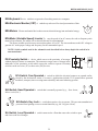
BA=Printed Circuit Board Insulating substrate on which a thin pattern of copper conductors has been
À
formed to connect discreet electronic components also mounted on the board.
CB=Circuit Breaker Automatic switch that opens an electric circuit in abnormal curÀ
rent conditions (e.g., an overload).
6
CD=Control, Time Delay Relay A relay whose contacts
À
switch only after a fixed or adjustable delay, once voltage has been applied to its coil. The contacts switch back to normal (de-energized state)
immediately when the voltage is removed.
À
CL=Control, Latch Relay A re la y w h ic h
latches in an energized or set position when operated
by one coil (the latch/set coil). The relay stays latched,
even though coil voltage is removed. The relay
releases or unlatches when voltage is applied to a
second coil, (the unlatch/reset coil).
CR=Control, Relay A relay whose contacts switch immediately
À
when voltage is applied to its coil and revert to normal when the voltage
is removed.
À
CP=Control, Photo-Eyes Photo-eyes sense the presence of
an object without direct physical contact. Photo-eyes consist of a transmitter, receiver, and output module.These components may be housed
in one assembly with the transmitter bouncing light off of a reflector to
the receiver, or these components can be housed in two separate assemblies with the transmitter pointed directly at the receiver.
The photo-eye can be set to turn on its output either when the light
beam becomes blocked (dark operate) or when it becomes unblocked
(light operate).
7
R
HOW TO USE MILNOR ELECTRICAL SCHEMATICS
R
CS=Control, Contactor/Motor Starter A relay capable of handling heavier electrical loads, usually a
À
motor.
EB=Electric Buzzer An audible signaling device.
À
EC=Electric Clutch A clutch consists of a coil and a rotor. The rotor has two separate rotating plates. These
À
plates are free to rotate independent of each other until the coil is energized. Once energized the two plates turn as
one.
ED=Electronic Display A visual presentation of data, such as an LCD (liquid crystal display), LED (light
À
emitting diode) display, or VFD (vacuum florescent display).
EF=Electric Fuse A fuse is an over-current safety device with a circuit opening fusible member which is
À
heated and severed by the passage of over-current through it.
EL=Electric Light Indicator lights may be either incandescent or fluorescent.
À
EM=Electro Magnet Solenoid A device consisting of a core surrounded by a wire coil through which an
À
electric current is passed. While current is flowing, iron is attracted to the core (e.g., a pinch tube drain valve solenoid).
ES=Electronic Power Supply A device that converts AC (alternating current) to filtered and regulated DC
À
(direct current). The input voltage to the power supply is usually 120 or 240 VAC . The output is +5, +12, and -12 VDC.
ET=Thermal Overload A safety device designed to protect a motor. A thermal
À
overload consists of an overload block, heaters, and an auxiliary contact. The auxiliary
contact is normally installed in a safety (three-wire) circuit that stops power to the motor
contactor coil when a motor overload occurs.
EX=Electrical Transformer A device that transfers electrical energy from
À
one isolated circuit to another, often raising or lowering the voltage in the process.
8
MSFD0106AE/95041V (2 of 5)
KB=Keyboard Device similar to a typewriter for making entries to a computer.
À
MN=Electronic Monitor (CRT) A cathode ray tube used for visual presentation of data.
À
MR=Motors Electro-mechanical device that converts electrical energy into mechanical energy.
À
MV=Motor (Variable Speed) Inverter To vary the speed of an AC motor, the volts to frequency ratio
À
must be kept constant. The motor will overheat if this ratio is not maintained.
The motor variable speed inverter converts three phase AC to DC. The inverter then uses this DC voltage to
generate AC at the proper voltage and frequency for the commanded speed.
NOTE: Switch symbols used in the schematics and described below always depict the switch in its
unactuated state.
PX=Proximity Switch A device which reacts to the proximity of an target
À
without physical contact or connection. The actuator or target causes a change in the
inductance of the proximity switch which causes the switch to operate. Proximity
switches can be two-wire (AC) or three-wire (DC) devices.
SC=Switch, Cam Operated A switch in which the electrical contacts are opened and/or
À
closed by the mechanical action of a cam(s). Applications include 35-50 pound timer operated
machines, autospot, timer reversing motor assembly, and some balancing systems.
SH=Switch, Hand Operated A switch that is manually operated (e.g., Start button,
À
Master switch, etc.).
SK=Switch, Key Lock A switch that requires a key to operate . This prevents unauthorized
À
personnel from gaining access to certain functions (e.g., the Program Menu).
SL=Switch, Level Operated A switch connected to a float that causes the switch to open
À
and close as the level changes.
9
HOW TO USE MILNOR R ELECTRICAL SCHEMATICS
SM=Switch, Mechanically Operated A switch that is mechanically operated by a part of
À
or the motion of the machine (e.g., door closed switch, tilt limit switches, etc.)
SP=Switch, Pressure Operated A switch consisting of a diaphragm that
À
pushes against a switch actuator.
ST=Switch, Temperature Operated A switch that is actuated at a preset temperature
À
(e.g., dryer safety probes) or has adjustable set points (e.g., Motometers or Combistats).
TB=Terminal Board A strip or block for attaching or terminating wires.
À
VE=Valve, Electric Operated A valve operated by an electric coil to control the flow of
À
fluid. The fluid can be air, water or hydraulics.
ZF=Rectifier A solid state device that converts alternating current to
À
direct current.
À
WC=Wiring Connector A coupling device for joining two cables or connecting a cable to an electronic
circuit or piece of equipment. Connectors are male or female, according to whether they plug into or receive the
mating connector.
10
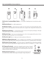
MSFD0106AE/95041V (3 of 5)
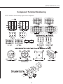
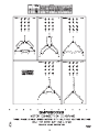
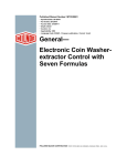
Component Terminal Numbering
NOTE: Numbers shown usually appear on the component.
11
HOW TO USE MILNOR R ELECTRICAL SCHEMATICS
R
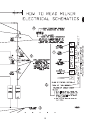
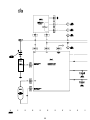
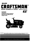
Features of Milnor Electrical Schematics
Document W6DRYGS+A shown on the next page, is part of an actual schematic for the Milnor Gas Dryer.
For the purposes of this instruction, the schematic is shown gray and explanations of the items on the schematic are
shown black.
The item numbers below correspond to the circled item numbers shown on the drawing.
¬ The first six characters of the drawing number (W6DRYG)indicate that this is a wiring diagram (W), identify the generation of controls (6), and identify the type of machine (DRYG=Gas Dryer). These characters
appear in the drawing number of every schematic in the set.
The characters following the first six are unique to each drawing. The two characters identified as the page
number are an abbreviation for the function performed by the depicted circuitry (S+=three-wire circuit) and
establish the order in which the schematic occurs in the manual (schematics are arranged in alpha-numeric
order in the manual).
Whenever circuitry changes are significant enough to warrant publishing a new schematic drawing, the new
drawing number will be the same as the old except for the major revision letter ( A in the example).
Included in the drawing title are the class of control system, the title of this circuit, and the circuit voltage.
® Line numbers are provided along the bottom edge of the drawing. These permit service personnel in the field
and at the Milnor factory to quickly relate circuit locations when discussing troubleshooting over the
phone. Page and line numbers are referenced on the drawing as explained in items five and six below.
¯ General functions of the circuit or portions thereof are stated across the top edge of the drawing.
° Relay contacts show the page and line number on which the relay coil may be found. This is the type of
cross referencing most frequently used in troubleshooting.
± Relay coils show the page and line number on which its associated contacts are located.
² Relay contacts and relay coils show the physical location of the relay.
12
MSFD0106AE/95041V (4 of 5)
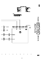
³ The designation MTA applies to electronic circuit board connections. Typically, a control system will con-
tain several different types of circuit boards and one or more boards of each type. A numerical suffix identifies the board type and a numerical prefix identifies which one of several boards of a given type is being
depicted. For example, the designation 1MTA5 identifies this as the first I/O board (8 output, 16 input
board) in the control system. As shown on the drawing, a pin number follows the board number, separated
by a dash. Thus, 1MTA5-9 is pin 9 on this board. The numerical designations for board types vary from one
control system to another. Some of the board types commonly encountered on the Mark II washer-extractor
control and their designations are as follows:
MTA1-MTA6 = 8 output, 16 input (8/16) boards.
MTA11-MTA16 = 16 output boards
MTA30-MTA40 = processor boards
MTA41-MTA43 = digital to analog (D/A) boards
MTA51-MTA56 = analog to digital (A/D) boards
The complete listing of the boards utilized in a given control system can be found in the component list for
that system.
´ The wire numbers, as described in the explanation of the signal routing table at the beginning of this section,
are shown at appropriate locations on the schematic drawing.
µ Where diamond symbols appear at the end of a conductor, these are match points for continuing the
schematic on another drawing. The page and line number that continues the circuit is printed adjacent to the
diamond symbol. Where more than one match point appears on the referenced page, match diamonds containing corresponding letters.
13
4
5
6
7
10
14
8
1
9
2
3
15
16
17
MTA2
BASP
MTA1
SWITCH PANEL/
DISPLAY BOARD.
BAUP
E-TIMER
PROCESSOR
BOARD
K6
K7
K5
K3
K4
K2
1
1
1
MTA3
MTA1
INPUTS
1
1
MTA2
K9
K8
K11
MTA5
K10
K13
1
K12
K15
MTA4
K14
1
MTA6
D
K0
WC
K1
S
WC
W
CV
REMOTE
TESTING
DISPLAY
CONNECTS
HERE
INVERTER
WC1
1MTD
ESPS
SMWVB
WC
WC2
OUTPUTS
1MTP
SPLL
MTA3
POWER
COMMUNICATE
OUTPUTS
EXHV
E
F
CRDC CRDL 7
1
A
E
F
7
1
B
TBA
GND CSVS
S
H
O
1
208/240
VOLT
ONLY
MICRO 6 SYSTEMS
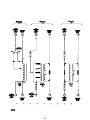
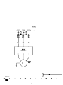
C4E CONTROL PANEL
PELLERIN MILNOR CORPORATION
W7C4ETG
2002474B
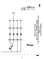
18
EXHV
RECTIFIER
B2T2002037
2002462G
W7C4ETG
2002474B
PELLERIN MILNOR CORPORATION
TBS
USE
COPPER
CONDUCTORS
ONLY
1=DETERGENT
2=BLEACH
3=SOFTENER
FLUSH VALVE
NOT USED
NOT USED
NOT USED
SUPPLY COMMON
1 2 3 4 5 6 7 8
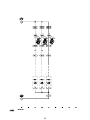
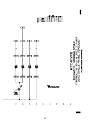
MICRO 6 SYSTEMS
C4E
CONTROL BOX LAYOUTS
CAUTION
IF AN EXTERNAL SUPPLY DISPENSER
IS TO BE CONNECTED NOTE THE FOLLOWING
1. SUPPLY SIGNALS ARE 240 VAC AT 9VA
(MAXIMUM OF 38 MILLIAMPS AT 240 VAC)
2. DO NOT USE MACHINE CONTROL VOLTAGE
TO POWER DISPENSER. POWER MUST
COME FROM A SEPARATE DISCONNECT.
W7C4ETG
INCOMING POWER
REQUIRES SEPARATE BRANCH
CIRCUIT PROTECTION
3P WIRE NUMBERS
L1
L2
L3
N/A
1P WIRE NUMBERS BL/WH WHITE
1
3
2
TERMINAL STRIP
GROUND
TBL
TBL4
SUPPLY
30”T5E
B2T2001002/2001294G
W7C4ETG
2002474B
19
20
21
22
23
24
25
26
27
28
29
30
31
32
33
34
35