1
LED-BOSS
COLORboss™
USER MANUAL
CHAUVET, 3000 N 29th Ct, Hollywood, FL 33020 U.S.A
(800) 762-1084 – (954) 929-1115
FAX (954) 929-5560
www.chauvetlighting.com
2006-01-26/12:15
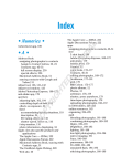
Table of Content
BEFORE YOU BEGIN....................................................................................................................................................... 3
WHAT IS INCLUDED .......................................................................................................................................................................................................... 3
UNPACKING INSTRUCTIONS .............................................................................................................................................................................................. 3
AC POWER ..................................................................................................................................................................................................................... 3
SAFETY INSTRUCTIONS .................................................................................................................................................................................................... 3
INTRODUCTION ............................................................................................................................................................... 4
FEATURES ....................................................................................................................................................................................................................... 4
DMX CHANNEL SUMMARY ............................................................................................................................................................................................... 4
PRODUCT OVERVIEW....................................................................................................................................................................................................... 5
SETUP .............................................................................................................................................................................. 5
DMX SETUP & ADDRESSING............................................................................................................................................................................................ 6
Setting the DMX address dipswitches ............................................................................................................................................................... 6
OPERATING INSTRUCTIONS .......................................................................................................................................... 7
CONTROL PANEL ............................................................................................................................................................................................................. 7
MANUAL OPERATION ....................................................................................................................................................................................................... 7
MENU DIAGRAM............................................................................................................................................................................................................... 7
DMX CONTROL MODE ..................................................................................................................................................................................................... 8
DMX Channel Values............................................................................................................................................................................................... 8
APPENDIX ........................................................................................................................................................................ 9
DMX PRIMER .................................................................................................................................................................................................................. 9
Fixture Linking .................................................................................................................................................................................................... 9
RETURNS PROCEDURE .................................................................................................................................................................................................. 10
CLAIMS ......................................................................................................................................................................................................................... 10
TECHNICAL SPECIFICATIONS .......................................................................................................................................................................................... 10
TECHNICAL SUPPORT .................................................................................................................................................................................................... 10
LED-BOSS User Manual
2
2006-01-26/12:15
BEFORE YOU BEGIN
What is included
NOTICE
This controller will work only with the LED-PAR196
COLORsplash™ product.
1 x COLORboss™
Users Manual
Warranty Card
Unpacking Instructions
Immediately upon receiving a product, carefully unpack the carton, check the contents to ensure that
all parts are present, and have been received in good condition. Notify the shipper immediately and
retain packing material for inspection if any parts appear damaged from shipping or the carton itself
shows signs of mishandling. Save the carton and all packing materials. In the event that a fixture
must be returned to the factory, it is important that the fixture be returned in the original factory box
and packing.
AC Power
To determine the power requirements for a particular product, see the label affixed to the back plate
of the product or refer to the product’s specifications chart. A product’s listed current rating is its
average current draw under normal conditions. All fixtures must be powered directly off a switched
circuit and cannot be run off a rheostat (variable resistor) or dimmer circuit, even if the rheostat or
AC Voltage Switch Example
dimmer channel is used solely for a 0% to 100% switch. Before applying
power, check that the source voltage matches the product’s requirement.
Check the product or device carefully to make sure that if a voltage
selection switch exists that it is set to the correct line voltage you will use.
Warning!
If applicable, verify that the power select switch on your unit
matches the line voltage applied. All fixtures must be
connected to circuits with a suitable Earth Ground.
Safety Instructions
Please read these instructions carefully, which includes important
information about the installation, usage and maintenance?
Please keep this User Guide for future consultation. If you
sell the unit to another user, be sure that they also receive
this instruction booklet.
Always make sure that you are connecting to the proper
voltage and that the line voltage you are connecting to is
not higher than that stated on decal or rear panel of the
fixture.
This product is intended for indoor use only!
To prevent risk of fire or shock, do not expose fixture to
rain or moisture. Make sure there are no flammable
materials close to the unit while operating.
The unit must be installed in a location with adequate
ventilation, at least 50cm from adjacent surfaces. Be sure
that no ventilation slots are blocked.
Always disconnect from power source before servicing or
replacing lamp or fuse and be sure to replace with same
lamp source.
Caution!
Secure fixture to fastening device using a safety chain.
Never carry the fixture solely by its head. Use its carrying
handles.
Maximum ambient temperature is Ta: 40°. Do not operate
fixture at temperatures higher than this.
In the event of serious operating problem, stop using the
unit immediately. Never try to repair the unit by yourself.
Repairs carried out by unskilled people can lead to
damage or malfunction. Please contact the nearest
authorized technical assistance center. Always use the
same type spare parts.
Don’t connect the device to a dimmer pack.
Make sure power cord is never crimped or damaged.
Never disconnect power cord by pulling or tugging on the
cord.
Avoid direct eye exposure to lamp while it is on.
There are no user serviceable parts inside the unit. Do not open the housing or
attempt any repairs yourself. In the unlikely event your unit may require service,
please contact CHAUVET.
LED-BOSS User Manual
3
2006-01-26/12:15
INTRODUCTION
Features
Control Features
4 channel DMX controlled (controller device)
7 independently selectable preset colors, 5 programmed
chases adjustable in speed or flash rate, Auto mode and
Sound Active
Select up to 20 par cans in a program
Speed, Flash or Chase control channel
Chase speed control channel
Features
Built in Microphone
Digital LCD display
DMX Channel Summary
CHANNEL
FUNCTION
1
Programs
2
Range of Fixtures
3
Control Options
4
Chase Speed
LED-BOSS User Manual
4
2006-01-26/12:15
Introduction
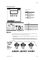
Product Overview
SEGMENT BUTTONS
BUTTONS
MENU
Used to navigate and select
controller functions
SETUP
Enter menu selection
UP
Increase data values for
menu options
DOWN
Decrease data values for
menu options
ITEM
A
B
C
E
D
SETUP
DESCRIPTION
A
3-Pin female XLR DMX input connector
B
3-Pin male XLR DMX output connector
C
DC input
D
Power switch
E
Built in Microphone
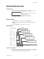
The setup of the par cans for control using the COLORboss™ is the same as if using a universal
DMX controller. You will first have to form a daisy chain connection.
1. Connect the (male) 3 pin connector side of the DMX cable to the output (female) 3 pin connector
of the first fixture.
2. Connect the end of the cable coming from the first fixture which will have a (female) 3 pin
connector to the input connector of the next fixture consisting of a (male) 3 pin connector. Then,
proceed to connect from the output as stated above to the input of the following fixture and so on.
Fix. 1 - Channel 1
4
6
8
1
3
5
7
256
2
64
128
7
32
5
8
3
16
9 10
4
4
2
128
2
1
32
64
8
8
16
6
4
2
4
1
ON
ON
LED-BOSS User Manual
Fix. 3 - Channel 15
2
1
7
256
128
8
64
32
6
5
8
3
16
4
2
1
1
Fix. 2 - Channel 8
256
Connect from the
DMX Output of the
controller to the
DMX Input of the
first fixture.
ON
5
9 10
9 10
2006-01-26/12:15
DMX Setup & Addressing
1. Enable DMX control on the LED-PAR196 COLORsplash™ by setting on all fixtures, dipswitch #
10 to the ON position, and then address each fixture accordingly. Slow Flow chase programs were
built on the control of 20 fixtures, in the controller these are referred to as “Part Amount”. In order
for the chase to operate correctly you must address the fixtures in 7 channel increments as shown
on the table following.
STARTING DMX CHANNEL ADDRESS ( PART AMOUNT )
Fixture
DMX
Address
1
2
3
4
5
6
7
8
9
10
11
12
13
14
15
16
17
18
19
20
001 008 015 022 029 036 043 050 057 064 071 078 085 092 099 106 113 120 127 134
S et t i n g t h e DM X ad dr es s di psw it ch es
This DMX mode enables the use of a universal DMX controller device. Each fixture requires a "start
address" from 1 to 511. A fixture requiring one or more channels for control begins to read the data
on the channel indicated by the start address. For example, a fixture that occupies or uses 7 channels
of DMX and was addressed to start on DMX channel 100, would read data from channels: 100, 101,
102, 103, 104, 105 and 106. Choose start addresses so that the channels used do not overlap and
notate the start address selected for future reference.
If this is your first time addressing a fixture using the DMX-512 control protocol than I suggest jumping
to the Appendix Section and read the heading “DMX Primer”. It contains very useful information that
will help you understand its use.
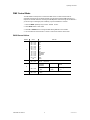
Set the start address using the group of DIP switches located usually on bottom of the fixture. Each
dip switch has an associated value. Adding the value of each switch in the ON position will provide
the start address. Determining which switches to toggle ON given a specific start address can be
accomplished in the following manner. By subtracting the largest switch value possible from the
selected start address until zero is achieved.
EXAMPLE STARTING ADDRESS
5 6
7
256
64
128
64
16
32
16
4
3
8
4
8 9 10
256
128
32
8
LED-BOSS User Manual
7
2
Address 233
4
= 16
=8
= 24
Resolving address using
simple math.
1 2
5 6
ON
Address 24
Pin # 5
Pin # 4
Total
1
=8
=2
= 10
1 2
3
2
Pin # 4
Pin # 2
Total
1
Address 10
ON
233 – (128) = 105, Turn ON Dip # 8
105 – (64) = 41, Turn ON Dip # 7
41 – (32) = 9, Turn ON Dip # 6
9 – (8) = 1, Turn ON Dip # 4
1 – (1) = 0, Turn ON Dip # 1
You will most likely use the first
available number which maybe
number 1. This number was
selected for example purposes.
6
4
8 9 10
DIP SWITCH
(DMX VALUE)
1
2
3
4
5
6
7
8
9
10
1
2
4
8
16
32
64
128
256
DMX Enable
2006-01-26/12:15
Operating Instructions
OPERATING INSTRUCTIONS
Control Panel
On the control panel you can set the controller on static colors, to run preset programs, to run by
sound-activation or assign a starting DMX channel address to the controller.
[MENU] Returns to Main menu or step backward through functions
[SET UP] Enters menu selection
[UP] Steps backward through data values
[DOWN] Steps forward through data values
MENU
SETUP
UP
DOWN
Manual Operation
1. Press the MENU button to select desired program. ( see Menu Diagram)
2. Press SETUP button to toggle available options for that program. (Options listed in Menu
Diagram)
3. Press UP or DOWN buttons to change values for the selected option.
Menu Diagram
Options
Programs/Function
1 Black
2 Static
RED
3 Static
Green
5 Static
Blue
4 Static
6 Static
7 Static
8 Static
Part Amount: [01] – [20]
Part Amount: [01] – [20]
Run Speed: [001] – [100]
Part Amount: [01] – [20]
Yellow
Flash Freq: [001] – [100]
Purple
Part Amount: [01] – [20]
Cyan
Chase: [01] – [16]
White
Run Speed: [001] – [100]
9 Color Change
10 Slow
11 Slow
Flow1
Part Amount: [01] – [20]
Flow2
Chase: [01] – [16]
12 Flash
13 Chase
14 Sound
Mode
15 DMX
Control
DMX Channel: 001 - 512
{ Part Amount: } Defined
Part Amount refers to the number of par cans to activate on the controller. It is an accumulative
selection not an individual selection. For example, you can select par 1 or 1-3, or 1-10 etc. With your
channel fader on the console raised full, all 20 pars would become visible.
LED-BOSS User Manual
7
2006-01-26/12:15
Operating Instructions
DMX Control Mode
The COLORboss™ will respond to 4 channels of DMX control. The same functions that are
accessible manually are also accessible remotely using an external universal DMX controller. It is
important to remember that when controlling the COLORsplash™ fixtures through the COLORboss™
you are no longer controlling the pars individually, only the COLORboss™ controller.
1. Press the MENU repeatedly until you reach “15 DMX Control”.
2. Press SETUP button to enter mode.
3. Press UP or DOWN buttons to change the DMX starting address for the controller.
4. You must leave this menu selection on screen in order for this mode to remain active.
DMX Channel Values
DEFAULT
VALUE
1
000 019
020 039
040 058
059 078
079 098
099 117
118 137
138 156
157 176
177 196
197 215
216 235
236 254
255
2
000 255
Qty of Fixtures
1 par can > 20 par cans
Color Change
Slow Flow1
Slow Flow2
Flash
Chase
Sound
000 255
Run Speed
1 > 100%
Flash Speed
1 > 100%
Chase Program
1 > 16
000 255
Chase Speed
1 > 100%
3
4
LED-BOSS User Manual
FUNCTION
Programs
Black
Red
Green
Yellow
Blue
Purple
Cyan
White
Color Change
Slow Flow 1
Slow Flow 2
Flash
Chase
Sound
8
2006-01-26/12:15
APPENDIX
DMX Primer
There are 512 channels in a DMX-512 connection. Channels may be assigned in any manner. A
fixture capable of receiving DMX-512 will require one or a number of sequential channels. The user
must assign a starting address on the fixture that indicates the first channel reserved in the controller.
There are many different types of DMX controllable fixtures and they all may vary in the total number
of channels required. Choosing a start address should be planned in advance. Channels should
never overlap. If they do, this will result in erratic operation of the fixtures whose starting address is
set incorrectly. You can however, control multiple fixtures of the same type using the same starting
address as long as the intended result is that of unison movement or operation. In other words, the
fixtures will be slaved together and all respond exactly the same.
DMX fixtures are designed to receive data through a serial Daisy Chain. A Daisy Chain connection is
where the DATA OUT of one fixture connects to the DATA IN of the next fixture. The order in which
the fixtures are connected is not important and has no effect on how a controller communicates to
each fixture. Use an order that provides for the easiest and most direct cabling. Connect fixtures
using shielded two conductor twisted pair cable with three pin XLR male to female connectors. The
shield connection is pin 1, while pin 2 is Data Negative (S-) and pin 3 is Data positive (S+). CHAUVET
carries 3-pin XLR DMX compliant cables, DMX-10 (33’), DMX-4.5 (15’) and DMX-1.5 (5’)
Figure 1 - DMX connector configuration
1
3
2
COMMON
INPUT
1
3
1
3
DMX +
2
2
DMX -
Resistance 120
ohm 1/4w between
pin 2 (DMX -) and
pin 3 (DMX +) of
the last fixture.
OUTPUT
Termination reduces signal errors and to
avoid signal transmission problems and
interference, it is always advisable to
connect a DMX signal terminator.
F ix t u re L i n k in g
Note!
If you use a controller with a 5 pin DMX output connector, you will need to use a 5
pin to 3 pin adapter. CHAUVET Model No: DMX5M.
The chart below details a proper cable conversion:
3 PIN TO 5 PIN CONVERSION CHART
LED-BOSS User Manual
Conductor
3 Pin Female (output)
5 Pin Male (Input)
Ground/Shield
Pin 1
Pin 1
Data ( - )signal
Pin 2
Pin 2
Data ( + ) signal
Pin 3
Pin 3
Do not use
Do not use
Do not use
Do not use
9
2006-01-26/12:15
Appendix
Returns Procedure
Returned merchandise must be sent prepaid and in the original packing, call tags will not be issued.
Package must be clearly labeled with a Return Merchandise Authorization Number (RA #). Products
returned without an RA # will be refused. Call CHAUVET and request RA # prior to shipping the
fixture. Be prepared to provide the model number, serial number and a brief description of the cause
for the return. Be sure to properly pack fixture, any shipping damage resulting from inadequate
packaging is the customer’s responsibility. CHAUVET reserves the right to use its own discretion to
repair or replace product(s). As a suggestion, proper UPS packing or double-boxing is always a safe
method to use.
Claims
Damage incurred in shipping is the responsibility of the shipper; therefore the damage must be
reported to the carrier upon receipt of merchandise. It is the customer's responsibility to notify and
submit claims with the shipper in the event that a fixture is damaged due to shipping. Any other claim
for items such as missing component/part, damage not related to shipping, and concealed damage,
must be made within seven (7) days of receiving merchandise.
Technical Specifications
WEIGHT & DIMENSIONS
Length.......................................................................................................................... 165 mm (6.5 in)
Width..............................................................................................................................63 mm (2.5 in)
Height .......................................................................................................................... 127 mm (5.0 in)
Weight....................................................................................................................... 0.65 Kgs (1.4 lbs)
POWER
Power............................................................................................................................ 9V DC, 500mA
CONTROL & PROGRAMMING
Data input ............................................................................................. locking 3-pin XLR male socket
Data output ........................................................................................ locking 3-pin XLR female socket
Data pin configuration ............................................................................pin 1 shield, pin 2 (-), pin 3 (+)
Protocols.....................................................................................................................DMX-512 USITT
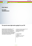
ORDERING INFORMATION
COLORboss™ ....................................................................................................................LED-BOSS
COLORsplash™ ............................................................................................................. LED-PAR196
Technical Support
Address:
Service Dept.
3000 N 29th Ct, Hollywood, FL 33020 (U.S.A.)
Support (Email):
[email protected]
Telephone:
(954) 929-1115 - (Press 4)
Fax:
(954) 929-5560 - (Attention: Service)
Website:............................................................................................... http://www.chauvetlighting.com
LED-BOSS User Manual
10
2006-01-26/12:15