1
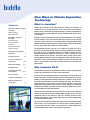
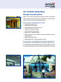
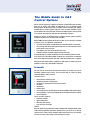
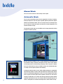
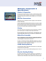
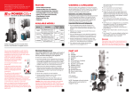
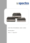
New Wave in Climate Separation
Technology
What is Invisidor?
Contents
New Wave in Climate Separation
Technology
1
What is Invisidor?
1
Why Invisidor CA2?
1
What Makes an Effective
Air Curtain
2
Patented Rectifier
2
Discharge Velocity
2
Air Volume
3
Discharge Temperature
3
Automatic Control
3
CDF Software for Air Curtains
4
Applications
Air Curtain Selection
Technical & Performance
Specifications
Dimensional Drawings
Hanging Brackets
The Biddle Guide to CA2
Control Options
5-6
7-10
11-12
13
14-16
Circular Doorways
17
Installation & Maintenance
17
Materials, Components &
Specifications
18
Invisidor CA air curtains are the ideal solution for retailers and consultants to
combat the issue of climate separation across their outlet or office building
doorway. Using a combination of rectifier technology, air velocity and temperature
control they deliver greater comfort to staff and customers alike, all year round,
in all weathers.
Managers of retail and commercial outlets know the importance of accessibility
for their customers. They also know that with this free form of access through
‘open door’ trading, comes the issue of cold draughts and high-energy bills. Now
Invisidor technology has been improved to deliver greater comfort for all, whether
it is in a supermarket, high street store or office building.
The Invisidor CA air curtain, does not act as a barrier in the place of a door, its
prime role is to reduce the amount of warm air leaving the building and condition
the incoming air to a comfortable temperature. BSRIA and Biddle research
produced documented evidence proving that air curtains operate best with
specific velocities and air volumes. The Invisidor CA air curtain satisfies these
needs by delivering the right air flow and temperature at the right time, reducing
energy loss. It is the only commercially available air curtain of its kind that now
offers a unique damper mechanism to improve efficiency, by controlling the
outlet velocity.
Why Invisidor CA2?
The new CA2 air curtain is the next generation of CA air curtains, incorporating new
energy saving technologies and a touch screen control panel.
The increased use of condensing boilers has necessitated a revised coil design to
ensure heat output is maintained despite the lower water temperatures. The key
principle is that the maximum discharge temperature is limited to 50°C, and this
can easily be provided with any water flow temperature above 70°C. There is a
small compromise on heat output on the maximum strength as water flow
temperatures approach 60°C, but on strengths 1-5 the outputs can generally be
maintained. The integral 3-port valve controls the discharge temperature to assist
in creating optimum comfort and efficiency.
Knowing that manual control of air curtains often leads to the incorrect setting the
inclusion of the energy saving self-regulating CHIPS technology ensures the most
appropriate setting at any moment in time. This automatic control has been
demonstrated to produce energy saving savings of up to 75% when compared with
a manual controlled air curtain.
The new b-touch control panel enables the installer and user to intuitively navigate
various menus, and set-up the CA2 air curtain for either automatic CHIPS or
manual control. Once the simple set-up procedure has been completed the
automatic CHIPS control renders manual operation superfluous.
1
What Makes an Effective Air
Curtain?
Patented Rectifier
A critical factor when selecting an effective air curtain is ensuring that incoming
air is conditioned to an acceptable temperature as it enters the building. For this
to be achieved, the air curtain jet must cover the full width of the building
entrance, so that it cannot be bypassed by incoming air. However, ensuring the
jet reaches the floor level is more challenging.
Along with the TNO wind facility at Apeldoorn in the Netherlands, Biddle has
successfully developed a patented rectifier to minimise turbulence in the
discharge airstream. By reducing the turbulence, the induction of the surrounding
air is also reduced, which increases the jet throw by 30-40% of an equal
volume/velocity unit. The pressure chamber behind the rectifier evenly distributes
the air stream across the whole width of the unit. The result is a deeply penetrating,
laminar airstream, reducing energy consumption and increasing comfort levels
Patented airflow rectifier
Entrance with no air curtain
all year round.
Entrance with inefficient air curtain
Entrance with Invisidor air curtain
Discharge Velocity
If the discharge velocity is too low then energy can be lost when the heated air
leaves through the upper part of the door opening, via the convective current.
Additionally, low velocities invariably do not reach floor level, resulting in the cold
air entering without being treated.
Ensuring that airflow reaches the floor in a doorway can be achieved by using a
high velocity jet. This, however, has a negative effect on the efficiency of the air
curtain. High velocity units create considerable turbulence in the surrounding
air. Furthermore, when the air meets the floor, it spreads both in and out of the
doorway, resulting in energy losses to the outside and creates internal draughts
and thermal discomfort for staff and customers.
Biddle Invisidor CA2 units are designed to be more effective in supplying the
curtain of air at the correct discharge velocity, when it is more comfortable and
where less energy is wasted.
2
Air Volume
On more demanding days it is usual to increase the operational speed of an air
curtain. Similarly on milder days the speed would be reduced. A standard air curtain
with a fixed area discharge grille, means the air velocity increases or decreases
accordingly, resulting in a drop in energy efficiency and comfort.
One of the important differences between the Biddle CA2 air curtain and a standard
air curtain is the inclusion of a patented damper mechanism. This assembly helps
maintain the optimum relationship between air volume and discharge velocity –
which we refer to as the air curtain strength or impulse.
Discharge Temperature
Biddle research showed that energy efficiency decreases with an increase in
Damper mechanism is automatically controlled by
PCB giving a controlled air strength
discharge air temperature. Hot air is more buoyant and reduces the effect of good
climate separation. Trials by Biddle investigated various temperatures, in order to
ascertain which one would be most efficient and provide the highest levels of
comfort throughout the year. Research found that a discharge temperature of
35°C ensures optimum comfort of those passing under the air curtain and anyone
close to the entrance. Temperatures up to 50°C can be useful in extreme and
demanding environments.
An air curtain will bring about air movement at low level within the building, close
to the door. Whether this is seen as comfortable is highly dependent on its
temperature. At the specified temperature, comfort is not compromised.
The Invisidor CA2 incorporates controls that automatically regulate the discharge
air temperature.
Automatic Control
Damper mechanism fully opened providing a
controlled air strength
Customer research has established that at the time of installation an air curtain
is typically set to operate at a mid-speed setting and rarely adjusted. This results
in the air curtain continually operating at a single air volume, velocity and
temperature. However as internal and external conditions constantly vary this
means the air curtain will only be operating at the optimum setting some of the
time, and for the rest of the time will be on either too high or too low a setting.
To ensure optimum performance, enhanced comfort and minimal energy loss as
conditions change the CA2 air curtain utilises CHIPS technology to automatically
adjust discharge velocity, air volume and discharge temperature. Outside, return
air and discharge temperature sensors are used to determine how much heat is
required and the bespoke control algorithm ‘translates’ the data into the strength
(a combination of air volume and velocity) required for optimal climate
b-touch control pad
3
separation and comfort.
CFD Software for Air Curtains
Application
CFD (Computational Fluid Dynamics) is a technique for modelling air flow and is
an ideal tool for simulating the effects of air curtains in real-life building scenarios.
It has already been used effectively during the design process of the Biddle air
curtain range to optimise parameters such as discharge temperature and velocity.
After extensive collaboration with the engineering department at the University of
Warwick, Biddle now has a CFD package specifically designed for modelling air
curtains and other ventilation equipment in the built environment. The program
takes account of various aspects of the building, including location, precise
geometry, leakage characteristics and wind profiles, to provide a solution unique
to the building under consideration.
This package has now been used successfully for over five years to provide
information that enables consultants and architects to specify the correct climate
separation system for their building from the earliest design stage. For example,
simulations can be undertaken to examine the effect various air curtain models
and different mounting configurations have, ensuring the final choice of unit
provides an effective solution without compromising specification.
Comparison of no air curtain v recessed air curtain.
Shows beneficial effects of climate separation.
The format of the CFD results depends on the situation modelled. They can be
presented as air temperature profiles, speed profiles or velocity vectors.
Without air curtain
With air curtain
The effect of building leakage
4
Air Curtain Selection
Product Selector
The ‘at a glance’ selector below will enable a simple selection of the most
appropriate product for your entrance environment application.
Please take time to consider the details on the following page. If you are unsure
which unit suits your application, please contact the Biddle sales office.
Air Curtain Product Selector
MOUNTING HEIGHT
4.0m
3.3m
2.8m
2.4m
• Medium High Street
Retail Outlets/
Small Offices/
Commercial
Reception Areas
(up to 200m2)
5
• Medium
Retail Outlets/
Foodstores/
Larger Commercial
Entrances
(200m2-2,5002m)
• Large
Retail Outlets/
Superstores/
Leisure Complexes
(2,000m2-6,0002m)
• Large
Retail Outlets/
Hypermarkets/
Department Stores/
Shopping Centres with
higher performance requirements
(5,000m2 plus)
Air Curtain Selection
Design Considerations
Biddle is part of your team. We work closely with consultants and architects
from the earliest design stages to ensure the optimum air curtain solution is
achieved for both new build and refurbishment projects.
Critical design considerations include:
•
•
•
•
•
•
•
Store location, layout and age
Building leakage characteristics
Positive/negative pressurisation of the store
Standard of mechanical air supplies
Entrance doorway, width and height
Multiple doors on different elevations
Employee awareness of the problems caused by leaving bulk store doors
open in foodstores
• Lobbied/no door environment
• Environmental factors - wind data, direction or speed
The selection of an appropriate air curtain depends on:
A. The door height (= mounting height, measured from floor to bottom of unit).
B. The door width (recommended unit overhang - minimum of 100mm each side).
C. The volume and temperature of the outside air entering through the open door.
6
Technical & Performance
Specifications
Invisidor CA2-S
•
•
•
•
•
Ideal for mounting up to 2.4m from floor to discharge
Next generation of air curtains - available today
Sets new standards of performance and efficiency
Medium High Street Retail Outlets/Small Offices/Commercial Reception Areas
(up to 200m2)
Brings high-tech appeal to any entrance
Water Heating
Electrical Heating
CA2-S
100 W
CA2-S
150 W
CA2-S
200 W
CA2-S
250 W
CA2-S
100 E
CA2-S
150 E
CA2-S
200 E
CA2-S
250 E
m
2.4
2.4
2.4
2.4
2.4
2.4
2.4
2.4
Optimum Door Width
m
0.8
1.3
1.8
2.3
0.8
1.3
1.8
2.3
Unit Width
m
1.0
1.5
2.0
2.5
1.0
1.5
2.0
2.5
kW
Model
Maximum Installation Height
Heating Capacity
Strength 1
Air Volume
2.5
3.7
4.8
6.1
2.5
3.7
4.8
6.1
2
3.3
4.9
6.6
8.3
3.3
4.9
6.6
8.3
3
3.8
5.7
7.6
9.4
3.8
5.7
7.6
9.4
4
4.7
7.1
9.5
11.9
4.7
7.1
9.5
11.9
5
5.4
8.1
10.8
13.5
5.4
8.1
10.8
13.5
6
8.3
12.5
16.7
20.8
8.3
12.5
16.7
20.8
Strength 1
m3/s
0.135
0.201
0.268
0.335
0.135
0.201
0.268
0.335
2
0.183
0.274
0.365
0.457
0.183
0.274
0.365
0.457
3
0.208
0.313
0.415
0.519
0.208
0.313
0.415
0.519
4
0.261
0.391
0.522
0.653
0.261
0.391
0.522
0.653
5
0.297
0.446
0.594
0.743
0.297
0.446
0.594
0.743
6
0.344
0.515
0.687
0.860
0.344
0.515
0.687
0.860
Water Flow Rate
l/s
0.10
0.15
0.20
0.25
n/a
n/a
n/a
n/a
Coil Hyd Pressure Drop (Max)
kPa
1.0
2.5
4.7
8.0
n/a
n/a
n/a
n/a
230v/1ph/50Hz
Electrical Supply
Max Power
Max Running Current
Noise Level at 3m
Weight (Dry)
@Strength 3
Model F
400v/3ph/50Hz
kW
0.20
0.30
0.40
0.49
10.5
15.6
21.0
26.1
A
0.89
1.33
1.77
2.22
3x16.0
3x23.8
3x32.1
3x39.9
dB(A)
36
38
39
40
36
38
39
40
kg
46
66
79
102
51
70
89
108
Model R
60
88
108
138
65
92
118
144
Model R(0)
54
78
95
122
59
83
105
128
Model C
58
83
102
130
63
87
112
136
Specification
Codes
Heating Capacities based on flow and return temperatures of 80/60°C, 20°C entering air and air outlet temperatures of:
•Strengths 1.5 = 35°C
•Strength 6 = 40°C
In operation, the outlet temperatures will vary between 20-50°C max
Correction Factors for other water flow temperatures
7
CA2 S-100 W
CA2 S-150 W
CA2 S-200 W
CA2 S-250 W
82/71°C
1.00
1.00
1.00
1.00
70/50°C
1.00
1.00
1.00
1.00
60/40°C
0.94
1.00
1.00
1.00
Note: Factors to be applied to the heating capacity at Strength 6 only
Technical & Performance
Specifications
Invisidor CA2-M
•
•
•
•
•
Ideal for mounting up to 2.8m from floor to discharge
Next generation of air curtains - available today
Sets new standards of performance and efficiency
Medium Retail Outlets/Foodstores/Larger Commercial Entrances
(200m2-2,5002m)
Brings high-tech appeal to any entrance
Water Heating
Electrical Heating
CA2-M
100 W
CA2-M
150 W
CA2-M
200 W
CA2-M
250 W
CA2-M
100 E
CA2-M
150 E
CA2-M
200 E
CA2-M
250 E
m
2.8
2.8
2.8
2.8
2.8
2.8
2.8
2.8
Optimum Door Width
m
0.8
1.3
1.8
2.3
0.8
1.3
1.8
2.3
Unit Width
m
1.0
1.5
2.0
2.5
1.0
1.5
2.0
2.5
kW
Model
Maximum Installation Height
Heating Capacity
Strength 1
Air Volume
2.8
4.1
5.5
6.9
2.8
4.1
5.5
6.9
2
4.1
6.1
8.2
10.2
4.1
6.1
8.2
10.2
3
4.9
7.4
9.9
12.4
4.9
7.4
9.9
12.4
4
6.4
9.7
12.9
16.2
6.4
9.7
12.9
16.2
5
7.5
11.3
15.0
18.8
7.5
11.3
15.0
18.8
6
11.0
16.5
22.0
27.5
11.0
16.5
22.0
27.5
Strength 1
m3/s
0.153
0.229
0.304
0.380
0.153
0.229
0.304
0.380
2
0.225
0.337
0.451
0.564
0.225
0.337
0.451
0.564
3
0.272
0.408
0.544
0.681
0.272
0.408
0.544
0.681
4
0.356
0.535
0.713
0.890
0.356
0.535
0.713
0.890
5
0.414
0.620
0.827
1.035
0.414
0.620
0.827
1.035
6
0.454
0.680
0.908
1.135
0.454
0.680
0.908
1.135
Water Flow Rate
l/s
0.13
0.20
0.27
0.34
n/a
n/a
n/a
n/a
Coil Hyd Pressure Drop (Max)
kPa
1.6
4.1
7.9
13.8
n/a
n/a
n/a
n/a
230v/1ph/50Hz
Electrical Supply
Max Power
Max Running Current
Noise Level at 3m
Weight (Dry)
@Strength 3
Model F
400v/3ph/50Hz
kW
0.28
0.42
0.56
0.70
14.0
20.8
28.0
34.8
A
1.30
1.95
2.60
3.26
3x22.7
3x33.8
3x45.5
3x56.5
dB(A)
37
39
40
41
37
39
40
41
kg
53
74
93
114
56
80
101
121
Model R
67
96
122
150
70
102
130
157
Model R(0)
60
87
108
134
63
92
116
140
Model C
65
91
116
142
68
97
124
149
Specification
Codes
Heating Capacities based on flow and return temperatures of 80/60°C, 20°C entering air and air outlet temperatures of:
•Strengths 1.5 = 35°C
•Strength 6 = 40°C
In operation, the outlet temperatures will vary between 20-50°C max
Correction Factors for other water flow temperatures
CA2 M-100 W CA2 M-150 W CA2 M-200 W CA2 M-250 W
82/71°C
1.00
1.00
1.00
1.00
70/50°C
1.00
1.00
1.00
1.00
60/40°C
0.83
0.93
0.98
1.00
Note: Factors to be applied to the heating capacity at Strength 6 only
8
Technical & Performance
Specifications
Invisidor CA2-L
•
•
•
•
•
Ideal for mounting up to 3.3m from floor to discharge
Next generation of air curtains - available today
Sets new standards of performance and efficiency
Large Retail Outlets/Superstores/Leisure Complexes (2,000m2-6,0002m)
Brings high-tech appeal to any entrance
Water Heating
Electrical Heating
CA2-L
100 W
CA2-L
150 W
CA2-L
200 W
CA2-L
250 W
CA2-L
100 E
CA2-L
150 E
CA2-L
200 E
CA2-L
250 E
m
3.3
3.3
3.3
3.3
3.3
3.3
3.3
3.3
Optimum Door Width
m
0.8
1.3
1.8
2.3
0.8
1.3
1.8
2.3
Unit Width
m
1.0
1.5
2.0
2.5
1.0
1.5
2.0
2.5
kW
5.8
8.6
11.6
14.4
5.8
8.6
11.6
14.4
7.6
11.4
15.2
19.0
7.6
11.4
15.2
19.0
3
9.5
14.3
19.1
23.8
9.5
14.3
19.1
23.8
4
12.3
18.4
24.5
30.7
12.3
18.4
24.5
30.7
5
14.5
21.7
28.9
36.1
14.5
21.7
28.9
36.1
6
22.1
33.2
44.2
55.3
22.1
33.2
44.2
55.3
Model
Maximum Installation Height
Heating Capacity
Strength 1
2
Air Volume
Strength 1
m3/s
0.318
0.476
0.636
0.794
0.318
0.476
0.636
0.794
2
0.419
0.627
0.838
1.047
0.419
0.627
0.838
1.047
3
0.525
0.786
1.048
1.311
0.525
0.786
1.048
1.311
4
0.675
1.012
1.350
1.688
0.675
1.012
1.350
1.688
5
0.796
1.193
1.591
1.988
0.796
1.193
1.591
1.988
6
0.912
1.369
1.826
2.281
0.912
1.369
1.826
2.281
Water Flow Rate
l/s
0.27
0.40
0.54
0.67
n/a
n/a
n/a
n/a
Coil Hyd Pressure Drop (Max)
kPa
2.9
7.6
16.4
11.1
n/a
n/a
n/a
n/a
230v/1ph/50Hz
Electrical Supply
Max Power
Max Running Current
Noise Level at 3m
Weight (Dry)
@Strength 3
Model F
400v/3ph/50Hz
kW
0.71
1.06
1.41
1.76
24.5
36.4
49.0
60.9
A
3.19
4.78
6.37
7.96
3x37.9
3x56.3
3x75.8
3x94.2
dB(A)
46
48
49
50
46
48
49
50
kg
65
96
122
155
69
104
137
170
Model R
83
121
156
198
87
129
171
213
Model R(0)
74
110
140
178
79
118
156
194
Model C
81
118
152
192
85
126
167
205
Specification
Codes
Heating Capacities based on flow and return temperatures of 80/60°C, 20°C entering air and air outlet temperatures of:
•Strengths 1.5 = 35°C
•Strength 6 = 40°C
In operation, the outlet temperatures will vary between 20-50°C max
Correction Factors for other water flow temperatures
9
CA2 L-100 W
CA2 L-150 W
CA2 L-200 W
CA2 L-250 W
82/71°C
1.00
1.00
1.00
1.00
70/50°C
1.00
1.00
1.00
1.00
60/40°C
0.69
0.82
0.89
0.80
Note: Factors to be applied to the heating capacity at Strength 6 only
Technical & Performance
Specifications
Invisidor CA2-XL
• Higher performance without the need for a larger unit
• Specifically designed to cope with up to 4m high doors or complex entrance
•
environments
Large Retail Outlets/Hypermarkets/Department Stores/Shopping Centres with
higher performance requirements (5,000m2 plus)
Water Heating
Electrical Heating
CA2-XL
100 W
CA2-XL
150 W
CA2-XL
200 W
CA2-XL
250 W
CA2-XL
100 E
CA2-XL
150 E
CA2-XL
200 E
CA2-XL
250 E
m
4.0
4.0
4.0
4.0
4.0
4.0
4.0
4.0
Optimum Door Width
m
0.8
1.3
1.8
2.3
0.8
1.3
1.8
2.3
Unit Width
m
1.0
1.5
2.0
2.5
1.0
1.5
2.0
2.5
kW
Model
Maximum Installation Height
Heating Capacity
Strength 1
Air Volume
6.9
10.4
13.8
17.3
6.9
10.4
13.8
17.3
2
9.1
14.0
18.3
22.9
9.1
14.0
18.3
22.9
3
11.6
17.4
23.1
28.9
11.6
17.4
23.1
28.9
4
15.0
22.5
30.0
37.6
15.0
22.5
30.0
37.6
5
17.8
26.8
35.7
44.6
17.8
26.8
35.7
44.6
6
26.8
40.2
53.6
67.0
23.5
34.6
46.6
57.9
Strength 1
m3/s
0.380
0.571
0.761
0.951
0.380
0.571
0.761
0.951
2
0.504
0.757
1.009
1.261
0.504
0.757
1.009
1.261
3
0.637
0.956
1.273
1.593
0.637
0.956
1.273
1.593
4
0.826
1.240
1.653
2.066
0.826
1.240
1.653
2.066
5
0.982
1.472
1.962
2.452
0.982
1.472
1.962
2.452
6
1.105
1.658
2.212
2.765
1.105
1.658
2.212
2.765
Water Flow Rate
l/s
0.33
0.49
0.65
0.82
n/a
n/a
n/a
n/a
Coil Hyd Pressure Drop (Max)
kPa
4.3
10.9
22.9
16.8
n/a
n/a
n/a
n/a
230v/1ph/50Hz
Electrical Supply
Max Power
Max Running Current
Noise Level at 3m
Weight (Dry)
@Strength 3
Model F
400v/3ph/50Hz
kW
1.17
1.75
2.34
2.92
24.5
36.4
49.0
60.9
A
5.27
7.91
10.54
13.18
3x38.6
3x57.5
3x77.3
3x96.1
dB(A)
52
53
55
56
52
53
55
56
kg
69
102
131
164
73
110
146
179
Model R
87
127
165
207
91
135
180
222
Model R(0)
78
116
149
187
83
124
165
203
Model C
85
124
161
201
89
132
176
216
Specification
Codes
Heating Capacities based on flow and return temperatures of 80/60°C, 20°C entering air and air outlet temperatures of:
•Strengths 1.5 = 35°C
•Strength 6 = 40°C
In operation, the outlet temperatures will vary between 20-50°C max
Correction Factors for other water flow temperatures
CA2 XL-100 W CA2 XL-150 W CA2 XL-200 W CA2 XL-250 W
82/71°C
1.00
1.00
1.00
1.00
70/50°C
1.00
1.00
1.00
1.00
60/40°C
0.63
0.75
0.82
0.74
Note: Factors to be applied to the heating capacity at Strength 6 only
10
Dimensions Free Hanging Model (F)
Dim
L
CA2-S/M
H
D
T
CA2-L/XL
1000-1500-2000-2500 1000-1500-2000-2500
270*
370*
590
774
1122-1622-2122-2622 1154-1164-2154-2654
*Add 27mm for hanging brackets
Notes: • The units of 2500mm wide have 3 suspension brackets, the third one of which is mounted half way along the unit’s length
• By removing the end panels, multiple units can be easily linked together
Dimensions Ceiling Recessed Model (R)
Dim
L
CA2-S/M
CA2-L/XL
1000-1500-2000-2500 1000-1500-2000-2500
H
270*
370*
D
565
745
S
80 - 125
80 - 125
A
92#
124#
B
260#
360#
C
Ø160
Ø250
*Add 27mm for hanging brackets
# Add 48mm for ceiling trims
unit length (L)
Number of Spigots per unit
Type
CA2-S/M
CA2-L/XL
1000
5
3
1500
7
5
2000
10
6
2500
12
8
Notes: • The units of 2500mm wide have 3 suspension brackets, the third one of which is mounted half way along the unit’s length
• Multiple units can be easily linked together
• The unit access panel is the full width of the unit. Adequate access through the ceiling is required for possible future
maintenance
11
Dimensions Bulkhead Recessed Model (R)(O)
Dim
L
H
CA2-S/M
CA2-L/XL
1000-1500-2000-2500 1000-1500-2000-2500
270*
370*
D
565
747
S
80 - 125
80 - 125
A
92#
124#
B
260#
360#
* Add 27mm for hanging brackets
# Add 48mm for ceiling trims
Notes: •
•
•
•
The units of 2500mm wide have 3 suspension brackets, the third one of which is mounted half way along the unit’s length
The bulkhead will need to be airtight to prevent poor incoming quality air
Multiple units can be easily linked together
The unit access panel is the full width of the unit. Adequate access through the ceiling is required for possible future
maintenance
Dimensions Cassette Model (C)
Dim
CA2-S/M
CA2-L/XL
L
1000-15002000-2500#
1000-15002000-2500#
H
270*
370*
D
821#
1105#
* Add 27mm for hanging brackets
# Add 48mm for ceiling trims
Notes: • The units of 2500mm wide have 3 suspension brackets, the third one of which is mounted half way along the unit’s length
• Multiple units can be easily linked together
12
Hanging Brackets
Ceiling Suspension Brackets (Standard)
Wall Mounting Brackets (Optional)
Design
Dim
Standard
CA2-L/XL
Dim
L
425
500
L
389
470
H
240
280
H
330
430
CA2-S/M
CA2-S/M
CA2-L/XL
Profiled Hanging Covers (Optional)
13
Unit installed with optional profiled hanging covers
The Biddle Guide to CA2
Control Options
CA2 air curtains operate by supplying air through a patented discharge rectifier/
grille. The air volume and velocity are adjusted by use of a patented control
damper within the discharge grille assembly. At lower strengths the damper
partially opens to create a greater ‘impulse’ to the air stream, providing a more
energy efficient air curtain. At higher strengths the damper opens fully to provide
an air volume and velocity to deal with more demanding situations.
All CA2 air curtains are delivered with a complete controls package allowing
numerous functions to be monitored and controlled.
Whilst a BMS interface module (which doesn’t allow any user control) is available
on request, units are supplied as standard with:
• a b-touch control panel, providing Manual or Automatic modes of operation
• a low voltage cable, with a RJ11 plug at both ends, for connecting the b-touch
control panel to the air curtain
• a pre-fitted 3-port valve (water heated units only)
• an built-in thyristor controller (electric heated units only)
and typically with an outdoor temperature sensor to facilitate optimum control.
If air curtains are to be linked together to operate in a ‘master/slave’ arrangement
then a low voltage ‘master/slave’ cable, with a RJ11 plug at both ends, is supplied.
Although the low voltage cable is supplied in a 25m length as standard, it can be
provided in a 5m, 15m or 50m length if requested.
b-touch
The new b-touch touchscreen control panel enables the installer and user to
intuitively navigate various menus, and set-up the CA2 air curtain for either
automatic CHIPS or manual control.
Functions such as:
•
•
•
•
•
•
•
•
•
two on/off time settings per day
minimum discharge air temperature
maximum fan speed (used to limit the noise level)
fan speed
speed boost
heating on/off
use normally open or normally closed contact from BMS or other remote device
access protection - screen ‘lock’ facility to prevent unauthorised access to settings
screen brightness
can be set and a display of:
•
•
•
•
operating strength
space temperature
filter dirty (time based)
error messages and codes
viewed.
Once the simple set-up procedure has been completed the automatic CHIPS control
renders manual operation superfluous. However if the user wishes to use manual
rather than the energy saving automatic CHIPS control then they can manually
turn the unit on/off, turn heating on/off and adjust fan speed.
14
Manual Mode
The user has basic control of on/off, heating and fan speed.
Automatic Mode
The air curtain automatically selects the most appropriate air volume, air velocity,
discharge temperature and heat output to provide optimum performance, highest
efficiency and maximum comfort. The user no longer needs to continually adjust
the fan speed or heating level when the inside and outside temperatures and
weather conditions change.
The Automatic control mode uses the CHIPS control strategy (Corrective Heating
& Impulse Prediction System).
Not only do external conditions such as outside temperature, wind velocity and
wind direction change continuously throughout the day, but the indoor climate
also changes because of heat build-up, frequency of door usage etc. It follows
that an air curtain needs to react as conditions change, and automatically adjust
its setting to ensure optimum comfort and efficiency.
In Automatic mode the CA2 air curtain utilises CHIPS technology to automatically
adjust discharge velocity, air volume, discharge temperature and heat output. Outside,
return air and discharge temperature sensors are used to determine how much
heat is required and the bespoke control algorithm ‘translates’ the data into the
15
strength (a combination of air volume and velocity) required for optimal climate
separation and comfort. Thus the user no longer needs to continually adjust the air
curtain’s setting when the inside/outside temperatures and/or weather change.
An air curtain with traditional control has heat and fan speed linked to one another.
When fan speed increases heat output will also increase, whether or not it’s
necessary, leading to a less effective and less efficient air curtain.
The CHIPS control strategy continually monitors and adjusts air volume, air velocity,
discharge temperature and heat output independently of each other so that the
point on the image where ‘Sufficient Heating’ and ‘Sufficient Strength’ intersect
is always achieved.
Heating
too little
sufficient
too much
Strength
too weak
1
2
3
4
5
6
7
8
9
sufficient
too strong
speed controller
= automatic CHIPS-Control
BMS Interface Module
Available on request, this allows operation of up to ten air curtains as a group
under the control of a BMS. It has a number of control inputs (which can vary the
air curtain strength, discharge air temperature, heating on/off and unit on/off)
requiring volt free contacts from the BMS. There are also a number of 24V outputs
that can report alarms back to the BMS.
Whilst the BMS interface module provides remote control of the group of air
curtains via the BMS, and the control panel can be used to program specific
settings, the control panel does not provide user control.
16
Circular Doorways
When an air curtain is to be used in conjunction with revolving doors or any other
form of circular doorway we are able to use a variant of the recessed model
installed either adjacent to or directly above the door. Given certain key dimensions
we manufacture a bespoke discharge grille to fit perfectly with the curvature of
the door, and ensure optimum climate separation around the circular doorway.
Installation & Maintenance
Units can be specified for free-hanging, cassette or recessed installation and all
are compatible with universal fixing systems, allowing longitudinal adjustment
for flush fitting.
The separately supplied suspension brackets can be inserted in the recesses in
the top of the unit and then fixed to a mounting rail to allow horizontal adjustment.
Special brackets are available for wall mounting. A full installer kit with separate
grilles is also supplied for recessed applications.
17
On delivery, all Invisidor units include detailed installer, control and wiring
instructions and maintenance notes.
Materials, Components &
Specifications
Control & Operation
The b-touch control panel regulates air volume, air velocity, discharge width
and temperature in either automatic or manual mode. It is connected to the
unit by a low-voltage data cable with RJ11 plugs. Multiple units are also connected
in this way.
Electric Connections
LPHW heated units are connected to the mains supply by a 2 metre cable with a
moulded, earthed plug.
The mains supply cable on electric heated units enters the air curtain via a cable
gland on the top of the unit. The cable is then connected to a terminal strip within
the unit. The water connections and low voltage connector plate are fitted to the
top of the unit to avoid the need for opening during installation.
Casing
The casing is made from zinc plated sheet steel and incorporates an inspection
panel. The inlet grilles have anodised aluminium grilles with fixed fins.
All casing components come in two standard colours - white (RAL 9016) or silver
aluminium (RAL 9006). Other RAL colours are available at an additional charge.
Motor/Fan Assembly
Units are supplied with two or more (depending on type) dual-inlet, vibration-free
suspended centrifugal fans driven by a two-side, suspended rotor motor. The fan
casing and impeller are made from zinc coated steel.
The motor is manufactured according to DIN 40050, protection class IP44 and
insulation class B. It is fitted as standard with thermal contacts which break the
circuit if the maximum motor temperature is exceeded.
LPHW Heating Battery
The heating battery comprises copper pipes and aluminium fins and a water supply
connection with a G1” female thread.
The test pressure is 30 bars and the maximum operating pressure is 6 bars at
110°C.
Electric Heating Battery
The electric heating battery is made from aluminium fins and incorporates an
electronic control unit, complete with overload protection. When the unit is
switched off, the fans will continue to rotate until the fins have sufficiently cooled.
18
• Biddle Air Systems Limited
St. Mary’s Road, Nuneaton
Warwickshire CV11 5AU
Tel: +44 (0)24 7638 4233
Fax: +44 (0)24 7637 3621
Email: [email protected]
http://www.biddle-air.co.uk
• Biddle B.V.
P.O. Box 15
NL-9288 ZG Kootstertille
The Netherlands
Tel: +31 (0)512 335555
Fax:+31 (0)512 331424
• Biddle GmbH
Emil - Hoffmann - Straße 55-59
50996 Köln
Germany
•
Tel: +49 (0)2236 96900
Fax:+49 (0)2236 969010
•
•
• Biddle
21 Allée de Vendanges
77183 Croissy Beaubourg
France
•
•
Tel: +33 (0) 1 64 11 15 55
Fax:+33 (0) 1 64 11 15 66
• Biddle NV
Business Park E19
Battelsesteenweg 455E
2800 Mechelen
Belgium
Tel: +32 (0) 15 287676
Fax:+32 (0) 15 287677
The information given in this brochure is, to the best of our knowledge, correct at the time of going to print.
However, Biddle Air Systems are constantly looking at ways of improving their products and services and
therefore reserve the right to change without prior notice any of the data contained in this publication.
1.12
Nine Point High - Nuneaton - 024 7634 6909 - [email protected]