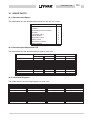
1
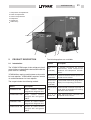
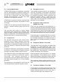
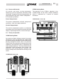
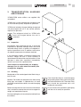
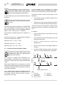
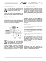
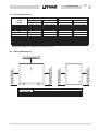
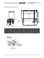
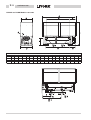
035B40022-000
I-i
Table of Contents
1
2
SUPPLIER INFORMATION
INSTALLATION
1.1
Introduction
1.1
4.1
Location
4.1
1.2
Warranty
1.1
4.2
Evaporator External Water System
4.1
1.3
Safety
1.1
4.3
Condenser External Water System
4.2
1.4
Emergency Stops/Shutdown
1.2
4.4
Water Connections
4.3
1.5
About this Manual
1.2
4.5
Refrigerant Connections
4.3
1.6
Safety Labels
1.3
4.6
Electrical Supplies
4.4
1.7
Material Safety Data
1.4
4.7
Electrical Connections
4.4
PRODUCT DESCRIPTION
5
COMMISSIONING
2.1
Introduction
2.1
5.1
Preliminary Checks
5.1
2.2
General Specification
2.2
5.2
Refrigerant Charging YCRM Units
5.1
2.3
Compressors
2.2
5.3
Starting
5.1
2.4
Refrigerant Circuits
2.2
5.3
Performance Check
5.2
2.5
Evaporators and Condensers
(Models 60 to 150)
5.5
Customer Handover
5.2
2.2
2.6
Evaporator (Models 170 to 280)
2.2
2.7
Condensers (Models 170 to 280)
2.2
2.8
Power and Controls
2.3
2.9
Theory of Operation
2.3
2.10 Nomenclature
3
4
2.4
TRANSPORTATION, HANDLING AND
STORAGE
3.1
Inspection
3.1
3.2
Handling
3.1
3.3
Anchorage
3.2
3.4
Storage
3.2
6
OPERATION
6.1
Control Panel
6.2
6.2
Unit Starting
6.2
6.3
Water Temperature Display
6.2
6.4
Alarm Display and Reset
6.3
6.5
Unit Shutdown
6.3
I-ii
7
035B40022-000
MAINTENANCE
10 SPARE PARTS
7.1
General Requirements
7.1
10.1 Recommended Spares
10.1
7.2
Daily Maintenance
7.1
10.2 Recommended Compressor Oils
10.1
7.3
Refrigerant Charge
7.2
10.3 Associated Diagrams
10.1
7.4
Compressors
7.2
7.5
Filter Drier
7.2
7.6
Sight Glass
7.2
7.7
Thermostatic Expansion Valve
7.3
7.8
Evaporator(s)
7.3
7.9
Condensers
7.3
8
TROUBLE SHOOTING
9
TECHNICAL DATA
9.1
Pressure Drop Graphs
9.1
9.2
Safety Switch Settings
9.4
9.3
Operational Limits
9.4
9.4
Physical Data
9.5
9.5
Unit Electrical Data
9.6
9.6
Compressor Electrical Data
9.6
9.7
Sound Power Levels
9.7
9.8
Space Requirements
9.7
9.9
Dimensions
9.8
9.10 Process and Instrumentation
Diagrams
9.11
11 DE-COMMISSIONING, DISMANTLING
AND DISPOSAL
11.1 General
11.1
035B40022-000
1-1
1
SUPPLIER INFORMATION
1.2
1.1
Introduction
The unit is supplied finished, tested and ready to
work. The unit warranty will be void if any
modification to the unit is carried out without written
agreement of York International.
York YCWM/YCRM Series chillers are
manufactured to the most stringent design and
construction standards to ensure high
performance, reliability and adaptability to all types
of air conditioning installations. The unit is intended
for cooling water or glycol and is not suitable for
purposes other than those specified in this manual.
If the unit is used improperly, or for different
purposes without the prior agreement of York
International or their agents, then such use would
be outside the scope and may be unsafe.
This manual contains all the information required
for correct installation and commissioning of the
unit, together with operation and maintenance
instructions. The manual should be read
thoroughly before attempting to operate or service
the unit.
With the exception of the operations detailed in this
manual, all installation, commissioning and
maintenance tasks must be performed by suitably
trained and qualified personnel from an Authorised
York Service Centre.
The manufacturer is not liable for injury or damage
resulting from incorrect installation/commissioning
or operation, insufficient maintenance and/or
failure to follow the procedures and instructions
contained in this manual.
Warranty
For warranty purposes, the following conditions
must be satisfied:
n
The initial start of the unit must be carried out
by trained personnel from an Authorised York
Service Centre.
n
Maintenance must be carried out by properly
trained personnel.
n
Only genuine York spare parts must be used.
n
All the scheduled maintenance operations
detailed in this manual must be performed at
the specified times.
Failure to satisfy any of these conditions will
automatically void the warranty.
1.3
Safety
The installation of the unit must be carried
out according to the Machinery Safety
Directive (CEE 89/392), (as modified by
Directive CEE 91/368, 93/44 and 93/68) to the
Low Voltage Directive CEE 73/23, to the
Electromagnetic Interference Directive CEE
89/336 and according to normal rules for
technical matters prescribed by the
applicable country regulations. Do not
operate the unit before having observed all
the above.
The unit must be earthed and no
installation or maintenance work
should be attempted on the electrical
equipment without first switching off
and isolating the main power supply
and any control supplies.
Failure to observance of the above safety
measures may result in fire or electrocution should
a short-circuit occur.
1-2
035B40022-000
The unit contains refrigerant vapour
and liquid under pressure within the
heat exchangers, compressors and
pipework. Release of refrigerant can
be a danger and cause injury.
It is the responsibility of the user to
ensure that the unit is suitable for the
conditions of use and that installation
and regular maintenance is carried out
by personnel with the appropriate
skills and in accordance with this
manual.
About this Manual
For safety reasons, the instructions contained in
this manual must be followed categorically;
furthermore, damage caused by misuse is not
covered by the warranty.
This manual uses the following conventions:
Warning messages alert you to a
specific procedure or practice which, if
not followed correctly, could cause
serious personal injury.
Support of the unit must be provided
as indicated in this manual, failure to
provide proper support may put
personnel at risk of injury.
Caution messages appear before
procedures which, if not observed, could
result in damage to the unit.
The unit is not designed to withstand
loads or stresses from adjacent
equipment, pipework and structures. Any
such extraneous loads or stress may
cause failure or collapse which can be a
danger and cause injury. In such cases
the warranty will be void.
Notes contain particularly important
comments which are set off from the text.
Do not discard or burn the packaging in
the environment.
1.4
1.5
Emergency Stops/Shutdown
Models 60 to 150
The ganged master switch adjacent to the control
panel will shutdown the unit when it is set to the
0 position.
Models 170 to 280
The isolator switch on the electrical panel will
shutdown the unit when the lever is pulled
downwards.
The contents of this manual, and of any other
document supplied with the unit, are the property of
YORK which reserves all rights. They may not be
reproduced, in whole or in part, without the written
authorisation of YORK.
035B40022-000
1.6
Safety Labels
Crankcase Heater Warning Label
The following labels are fitted to each unit.
Refrigerant Identification Label
Test Certificate
Unit Identification Label
Electrical Warning Label
1-3
1-4
1.7
035B40022-000
Material Safety Data
Refrigerant Data:
Safety Data
R22, R407C
Toxicity
Low.
In contact with skin
Liquid splashes or spray may cause freeze burns. Unlikely to be hazardous
by skin absorption. R22 may be slightly irritant and liquid has a degreasing
effect. Thaw affected areas with water. Remove contaminated clothing
carefully - may adhere to skin in case of freeze burns. Was affected areas
with plenty of warm water. If symptoms occur (irritation or blistering) obtain
medical attention.
In contact with eyes
Vapour has no effect. Liquid splashes or spray may cause freeze burns.
Immediately irrigate with eyewash solution or clean water for at least 10
minutes. Obtain immediate medical attention.
Ingested
Highly unlikely to occur - but should this occur freeze burn will occur. Do not
induce vomiting. Provided patient is conscious, wash mouth with water and
give about 250 ml (0.5 pint) to drink. Obtain immediate medical attention.
Inhalation
R22: High levels of vapour
concentration initially produce
stimulation and then depression of
the central nervous system causing
headaches and giddiness and may
lead to unconsciousness. Can prove
suddenly fatal if the exposure has
been severe.
R407C: High atmospheric
concentrations
may
lead
anaesthetic effect, including loss of
consciousness.
Very
high
exposures may cause an abnormal
heart rhythm and prove suddenly
fatal.
At higher concentration there is a danger from asphyxiation due to reduced
oxygen content of atmosphere. Remove patient to fresh air, keep warm and
at rest. Administer oxygen if necessary. Apply artificial respiration if
breathing has ceased or shows signs of failing. In event of cardiac arrest
apply external cardiac massage. Obtain immediate medical attention.
Further Medical Advice
Symptomatic and supportive therapy is indicated. Cardiac sensitisation
has been described which may, in the presence of circulating
catecholamines such as adrenalin, give rise to cardiac arrhythmias and
subsequent arrest following exposure to high concentrations.
Long term exposure
R22: A lifetime inhalation study in
rats and mice give a small excess in
salivary gland tumours in male rats
only at 50,000 ppm. 10,000 ppm
showed no effect. This information
suggests that R22 does not
represent a carcinogenic hazard to
humans.
Occupational exposure limits
R407C: A lifetime inhalation study in
rats has shown that exposure to
50,000 ppm resulted in benign
tumours of the testis. This is not
considered to be of relevance to
humans exposed to concentrations
at or below the occupational
exposure limit.
R 2 2 : R e c o m m e n d e d l i m i t : R407C: Recommended limit: 1000
1000 ppm v/v - 8 hr TWA 1250 ppm ppm v/v - 8 hr TWA.
v/v - 12 hr TWA.
Stability
R22: Unstable.
R407C: Not specified.
Conditions to avoid
Use in presence of naked flames, red hot surfaces and high moisture
levels.
035B40022-000
Hazardous reactions
1-5
May react violently with sodium, potassium, barium and other alkali and
alkaline earth metals. Incompatible materials : Magnesium and alloys
containing more then 2% magnesium.
Hazardous decomposition products R22: Halogen acids formed by R407C: Halogen acids by thermal
thermal decomposition.
decomposition and hydrolysis.
General precautions
Avoid inhalation of high concentrations of vapours. Atmospheric
concentrations should be minimised and kept as low as reasonably
practicable below the Occupational exposure limit. The vapour is heavier
than air and collects at low level and in confined areas. Ventilate by
extraction at lowest levels.
Respiratory protection
Where doubt exists on atmospheric concentration, HSE approved
breathing apparatus should be worn. This should be self contained or of the
long breather type.
Storage
Keep containers dry and in a cool place away from fire risk, direct sunlight,
and all sources of heat such as radiators. Keep at temperatures not
exceeding 45 °C.
Protective clothing
Wear overalls, impervious gloves and goggles/face protection.
Spill / Leak procedure
Ensure suitable personal protective clothing and respiratory protection is
worn. Provided it is safe to do so, isolate the source of the leak. Allow small
spillages to evaporate provided there is suitable ventilation.
Large spillages : Ventilate area. Contain spillages with sand, earth or any
suitable absorbent material. Prevent liquid from entering drains, sewers,
basements and work pits since vapour may create a suffocating
atmosphere.
Disposal
Best to recover and recycle. If this is not possible, destruction is to be in an
approved facility which is equipped to absorb and neutralise acids and
other toxic processing products.
Fire extinguishing data
R22: Non-flammable
Containers
Fire exposed containers should be kept cool with water sprays. Containers
may burst if overheated.
Fire fighting protective equipment
Self contained breathing apparatus and protective clothing must be worn in
fire conditions.
R407C: Non-flammable
atmospheric conditions.
at
1-6
035B40022-000
REFRIGERANT OIL DATA
Safety Data
Oil
Classification
Non-hazardous
In contact with skin
Minimally irritating. No first aid necessary. Exercise reasonable personal
cleanliness including cleansing exposed skin areas several times daily with
soap and water. Launder soiled work clothes at least weekly.
In contact with eyes
As with most foreign materials flush with plenty of eyewash solution or
clean water.
Ingested
Obtain immediate medical attention.
Inhalation
Obtain immediate medical attention.
Conditions to avoid
Strong oxidisers, caustic or acid solutions, excessive heat. May degrade
some paints and rubber materials.
Respiratory protection
Use in well ventilated areas
Protective clothing
Goggles or face shield should be worn. Gloves not necessary, but
recommended, especially for prolonged exposure.
Spill / Leak procedure
Wear suitable protective equipment, especially goggles. Stop source of
spill. Use absorbent materials to soak up fluid (i.e. sand, sawdust, and
commercially available materials).
Disposal
Incinerate the oil and all associated wastes in an approved facility in
accordance with local laws and regulations governing oily wastes.
Fire extinguishing data
Use dry chemical, carbon dioxide or foam spraying water on hot or burning
liquid, may cause frothing or splashing.
If a leak or spill has not ignited use water spray to disperse the vapours and
to provided protection for persons attempting to stop the leak.
Containers
Fire exposed containers should be kept cool with water sprays.
Fire fighting protective equipment
Self contained breathing apparatus should be worn in fire conditions.
035B40022-000
1
2
3
4
5
6
2-1
Compressor Compartment
Power Compartment
Control Compartment
Evaporator
Condenser
Cable Entry
2
3
4
1
1
6
2
PRODUCT DESCRIPTION
2.1
Introduction
5
The following options are available:
Option
Description
The YCWM/YCRM range of twin refrigerant circuit
water chillers are designed to be located inside the
plant room of a building.
Acoustic
Kit
(170-280)
A factory installed kit using
acoustically lined compressor
enclosure and compressor acoustic
covers.
YCWM chillers require a cooling tower or dry cooler
for heat rejection. YCRM chillers require a remote
air cooled condenser for heat rejection.
Remote
Control Kit
A field mounted control panel to
provide remote control.
The range includes the following models:
Pressure
Gauge Kit
(170-280)
Factory fitted mechanical gauge kit for
display of unit operating parameters.
Manifold
Kit
Field mounted manifolds to provide a
single point of connection for leaving
and return water circuits.
F l o w
Switch Kit
Field mounted flow switches for
evaporator water circuits.
Models
Description
YCWM 60 to 280
W a te r C o o l e d c h i l l e r s
charged with refrigerant R22
YCWM-B 60 to 280
W a te r C o o l e d c h i l l e r s
charged with refrigerant
R407C
YCRM 60 to 280
Remote Air Cooled chillers
charged with refrigerant R22
YCRM-B 60 to 280
Remote Air Cooled chillers
charged with refrigerant
R407C
2-2
2.2
035B40022-000
General Specification
YCWM/YCRM models are completely assembled
with all interconnecting refrigerant piping and
wiring ready for field installation. After assembly a
full run test is performed, with water flowing
through the evaporators, to verify that each
refrigerant circuit operates correctly.
YCWM units are pressure tested, evacuated and
fully charged with refrigerant and include an initial
oil charge.
YCRM units are pressure tested, evacuated and
include a nitrogen holding charge and initial oil
charge.
The unit base and frame is of heavy gauge
galvanised steel fastened with stainless steel
screws and bolts. All panels are easily removed for
access to components. Galvanised steel parts are
painted with baked-on enamel coloured blue.
2.3
Compressors
The hermetic compressors have internal motor
protection and an internal overflow valve from
discharge to suction. Starting is direct on line. The
compressors are mounted on rubber anti-vibration
pads and housed in a separate acoustically lined
enclosure.
Compressor lubrication is force-fed by a reversible
oil pump to all crankshaft and bearing surfaces
through a fine mesh stainless steel oil strainer.
The compressor motors are refrigerant gas cooled,
with integral thermistor protection against
o v e r l o a d s . T h e o v e r l o a d p r o t e c t i o n is
automatically reset after approximately 8 seconds.
The motor terminal boxes are to IP-54 weather
protection.
The compressors are switched On and Off by the
unit microprocessor to provide capacity control,
2.4
Refrigerant Circuits
Two complete refrigerant circuits are supplied on
each unit. All piping is ACR copper, with brazed
joints. Refrigerant circuits include: a service valve
for refrigerant charging, suction discharge and
liquid line isolating valves, a sight glass with
moisture indicator and thermostatic expansion
valve. High and low pressure switches and a
filter/drier are also included.
2.5
Evaporators and Condensers
(Models 60 to 150)
Each of the two evaporators and condensers is a
stainless steel plate type heat exchanger thermally
insulated with flexible closed cell material. Design
working pressure is 10 bar g on the water side and
30 bar g on the refrigerant side. An electric heater
mat and differential pressure switch is provided.
Each exchanger is provided with flow and return
water connections. Water connection is via 1 inch
gas threaded connections on models 60 and 75
and 1½ inch gas threaded connections on models
90 to 150.
2.6
Evaporator (Models 170 to 280)
The single dual-circuit steel shell and copper tube
evaporator is a direct-expansion type. It has
refrigerant in the tubes, which are formed in a hairpin configuration, and chilled liquid flowing through
the baffled shell. The evaporator is covered with
flexible, closed-cell, foam insulation.
Water connection to the evaporator is via victualic
type connections. The evaporator has a heating
element controlled by a thermostat. Water vent and
drain connections are included on the evaporator.
The evaporator design working pressure on the
water side is 10 barg and 30 barg on the refrigerant
side.
2.7
Condensers (Models 170 to 280)
The condensers are shell and tube type with a builtin sub-cooler and removeable water heads. The
design working pressure on the water side is
10 barg and 30 barg on the refrigerant side.
035B40022-000
2.8
Power and Controls
2-3
YCRM Cooling Mode
All controls and motor starting equipment
necessary for full unit operation are factory wired
and tested. The power and control components are
separated within the panel, which is designed to
IP-53 weather protection.
The operation of the YCRM is identical to the
YCWM except for the water cooled condenser
which is replaced by a remote air cooled
condenser.
Power Compartment
YCWM Models 170 to 280
The power compartment contains compressor
contactors, fuses and supply protection.
Control Compartment
The control compartment contains an electronic
circuit board and a soft touch key control panel with
display of operating functions, alarms and stops.
2.9
Theory of Operation
YCWM Cooling Mode
Low pressure liquid refrigerant enters the cooler
(Evaporator) and is evaporated and superheated
by the heat energy absorbed from the chilled water
passing through the cooler shell. Low pressure
vapour enters the compressor where pressure and
superheat are increased. Heat is rejected by the
water cooled condenser. The fully condensed and
subcooled liquid refrigerant then enters the
expansion valve where pressure reduction and
further cooling takes place before returning to the
cooler.
YCWM Models 60 to 150
2-4
035B40022-000
2.10 Nomenclature
YC W
M-B
90
YORK CHILLER
W - WATER COOLED
R - REMOTE AIR COOLED
PRODUCT TYPE
REFRIGERANT
Blank = R22
B
= R407C
MODEL
(NOMINAL kW)
035B40022-000
3
3-1
TRANSPORTATION, HANDLING
AND STORAGE
YCWM/YCRM series chillers are supplied fully
assembled.
YCWM units are pre-charged with refrigerant and
oil in the correct quantity required for operation.
YCRM units include a nitrogen holding charge and
are pre-charged with oil in the correct quantity
required for operation.
The refrigerant circuit on YCRM units
must be charged before the unit is
operated.
3.1
Inspection
Immediately upon receiving the unit, it should be
inspected for possible damage which may have
occurred during transit as goods are shipped exworks at purchaser's risk. In addition, ensure that
all ordered components have been received.
If any damage is evident, it should be noted on the
carrier's freight bill and a claim entered in
accordance with the advice note instructions. If the
damage is other than superficial, immediately
advise your local York representative.
York accepts no responsibility for shipping
damage, even in cases where the factory has
arranged for shipping.
3.2
Handling
Models 60 to 150 are designed to be lifted using a
fork lift truck.
Models 170 to 280 are designed to be lifted using
lifting lugs and cables. A spreader bar or frame
should be used with the cables, to avoid damaging
the unit.
Care should be taken to avoid damaging
the paneling when lifting and moving the
unit to the installation site. The sides of the
unit should be protected with stiff
cardboard or plywood.
Before moving the unit ensure that the installation
site is suitable to receive the unit and to support its
weight and mechanical impact.
Do not remove the protective packaging
until the unit is ready for operation.
During handling the unit should not be inclined from
the vertical.
3-2
3.3
035B40022-000
Anchorage
YCWM/YCRM series chillers are provided with
18 mm diameter holes in the base frame for
retaining the unit if required.
3.4
Storage
If the unit is to be stored prior to installation, certain
precautions should be taken to prevent damage,
corrosion or deterioration:
n
Ensure that all openings, such as water
connections, are securely capped or sealed.
n
Do not store where exposed to ambient air
temperatures exceeding 45°C for R22 or 42°C
for R407C units, preferably out of direct
sunlight.
n
Store the unit in a location where minimum
activity is likely to take place to limit the risk of
accidental damage.
n
Do not steam clean the unit.
n
Remove the keys necessary to gain access to
the control panel and deposit them with a
responsible person on site.
Periodic visual examination during storage is
recommended.
4-1
035B40022-000
4
INSTALLATION
4.1
Location
Before installing the unit, make sure
that the building structure and/or
mounting surface can support the unit
weight. Overall weights are detailed in
Section 9.
The unit has been designed for floor mounting in
protected indoor locations.
The flow switch must be connected in
series with other external interlocks. The
flow switch should be installed on the
pump delivery, upstream of the unit.
A Normally Open differential pressure switch may
be installed instead of the flow switch. The
pressure switch senses water pressure drop
across the evaporator.
In addition:
n
Install a filter/strainer on the inlet side of the
evaporator(s).
n
Install shutoff valves on the evaporator(s) inlet
and outlet water lines.
n
Install a valved by-pass around the
evaporator(s).
n
Install air vent valves at the highest points of
the lines.
The external water system should consist of the
following:
n
Provide suitable drainage points (with plugs,
cocks etc.) at the lowest points of the lines.
n
A circulation pump providing sufficient flow
and hydraulic head.
n
Insulate the pipework to prevent heat loss.
n
The primary system water content should be
no less than 10 litres per kW of cooling
capacity. If the total volume in primary system
pipework and evaporator is insufficient, an
insulated reservoir tank should be installed.
This tank will ensure that repetitive starts of the
compressors are avoided.
The installation site should ensure adequate
clearances and drainage for maintenance, refer to
Section 9 for details.
Evaporator External Water System
The external water hydraulic circuit must
ensure constant water flow to the
evaporator(s) under all operating or
adjustment conditions.
n
F
F1
I
R
S
T
S
T
S
S1
I
A diaphragm-type expansion tank with safety
valve outlet which must be visible.
The tank should be sized to
accommodate a 2% increase in total fluid
volume in the system (evaporator, lines,
user circuits and reservoir tank where
provided). The expansion tank does not
need to be insulated, as water does not
normally circulate therein.
n
S
Evaporator
4.2
A flow switch to deactivate the unit when water
is not circulating.
R
External Water System
Key
I
T
S
S1
Pressure
Temperature
Gate valves
By-pass valve
R Drain tap
F Strainer
F1 Flow switch
4-2
035B40022-000
Before filling the system, ensure that it is
free from foreign matter, sand, stones,
rust flakes, solder, slag or other materials
which could damage the evaporators.
It is advisable to by-pass the unit when flushing out
the lines.
Water used to fill the circuit may have to
be treated to ensure that the pH value is
correct.
Standard evaporators provided on YCWM/YCRM
units are designed to chill mixtures of water and
ethylene glycol with a corrosion-inhibiting additive
down to -10 °C (R22) and -5 °C (R407C).
If these methods are not available, or a cooling
tower is not the source of cooling water, then a
three way valve recirculation system can be used.
The external water system should consist of the
following:
n
A circulation pump providing sufficient flow
and hydraulic head.
n
The primary system water content should be
no less than 5 litres per kW of cooling capacity.
The water used for the condenser external water
system should have a hardness value within 10 to
15 °Fr.
In addition:
The amount of ethylene glycol to be added is as
follows.
n
Install a filter/strainer on the inlet side of the
condenser(s).
Amounts are shown as a percentage by weight of
the circuit design water content:
n
Install shutoff valves on the condenser(s) inlet
and outlet water lines.
n
Install a valved by-pass around the
condenser(s).
n
Install air vent valves at the highest points of
the lines.
n
Provide suitable drainage points (with plugs,
cocks, etc.) at the lowest points of the lines.
operation from + 5 to 0 °C : 20%
operation from 0 to -5 °C : 30%
operation from -5 to -10 °C : 40%
4.3
Condenser External Water System
The external water hydraulic circuit must
ensure constant water flow to the
condensers under all operating or
adjustment conditions.
Condenser
For cooling of YCWM units, condensers are
usually piped in conjunction with a cooling tower,
although in some cases they can be cooled by well
water.
S
F
I
R
S
With water cooled units it is necessary to control
coolant flow and/or temperature into the condenser
to maintain refrigerant pressure constant to ensure
satisfactory operation.
For a cooling tower system the simplest forms of
control are to use fan cycling, fan speed control, or
air damper control, with the tower having a
thermostat in its sump.
F1
T
S
T
S
S1
I
R
External Water System
Key
I
T
S
S1
Pressure
Temperature
Gate valves
By-pass valve
R Drain tap
F Strainer
F1 Flow switch
035B40022-000
4.4
Water Connections
The water inlet and outlet connections
must be connected correctly as shown on
the labels fitted next to the fittings.
Connect the external water supply lines to the
water inlet and outlet fittings on the unit, refer to
section 9 for diameters and locations.
YCWM 60-150 Heat Pump
The YCWM unit can operate as a water to water
heat pump by reversing the cycle on the water
circuits using three way valves. Pressostatic two
way valves are available as an option for remote
location in the condenser water pipework.
4.5
4-3
Refrigerant Connections
For cooling of YCRM units, condensers are usually
of the remote air-cooled type either roof or ground
level mounted. Refrigerant systems should be
designed and installed by suitably qualified
persons in compliance with relevant national codes
and standards. The complete pipework system
and condenser must have a Design Working
Pressure of at least 30 barg.
When the unit has been located in its final position,
t h e re f r i g e r a n t s y s t e m p i p e w o r k c a n b e
connected. Pipework and fittings MUST be
separately supported and not cause any loading on
the unit. Flexible connections are recommended
and will also minimise transmission of vibrations to
the building.
Pipework Design
The following notes give guidance but should not
be considered exhaustive.
P-traps and double risers may be required when
the condenser is sighted above the unit. Horizontal
runs of the liquid line should be inclined slightly
towards the YCRM unit.
An in-line receiver should not be installed in the
refrigerant system.
This type of operation is possible only if
the condensers are supplied with well
water or disposable water. The system
cannot be used if a cooling tower is used.
The unit is supplied as standard in the cooling
mode only. If necessary the change to heating
mode is carried out by York Personnel during
commissioning and first time strart-up of the unit,
when requested.
Where the condenser is above or level with the
unit, the discharge line should rise to at least the
top edge of the condenser at some point. This will
prevent liquid draining back to the compressor
during the off cycle.
Elbows, bends and valves should be minimised to
reduce pressure drop and prevent loss of
performance. The liquid line in particular should be
designed for minimum pressure drop to avoid
flashing in the liquid line which will cause loss of
performance and fault conditions to
occur. Particular care should be taken where the
condenser is below or level with the unit.
4-4
035B40022-000
Refrigerant Connections
Units are supplied with a nitrogen holding
charge.This should be relieved carefully via the
suction service connections and the liquid line
service connections.
The pipework can be brazed directly onto the
welding connections taking care to protect the unit
from excess heat which may cause distortion.
System Testing
All newly installed pipework must be pressure /
leak tested to national code requirements
(normally 1.1 x Design Working Pressure) then
fully evacuated before charging. Refer to the
section 5 for correct charging methods.
Incorrectly or badly designed and/or
installed pipework systems may
invalidate unit warranty
4.6
Electrical Supplies
Ensure that the power supply is off
before working on the electrical
system.
The unit must be provided with an
earth connection.
It is the installers responsibility to ensure
that all external wiring complies with
applicable safety regulations.
Supply and isolating devices shall be designed so
that the lines are fully independent. Magnetic
thermal differential breakers are recommended, to
prevent damage due to electrical phase loss.
Power supplies to the compressors are through
contactors controlled by the control panel. Each
motor is provided with an internal thermal overload
cut-out and external fuses.
Supply cables should be routed through the cable
entries on the unit and enter the electrical panel
through the hole.
4.7
Electrical Connections
The installation of the unit on the final site
must be carried out according to the
Machinery Safety Directive (CEE 89/392), (as
modified by Directive CEE 91/368, 93/44 and
93/68) to the Low Voltage Directive CEE 73/23,
to the Electromagnetic Interference Directive
CEE 89/336 and according to normal rules for
technical matters prescribed by country
regulations. Do not operate the unit before
having observed all the above. Supply lines
shall consist of insulated copper conductors
sized for maximum current draw.
Terminal connections should be made in
accordance with the connection diagram in this
manual and the diagram supplied with the unit.
Before connecting the supply lines, check
that the mains voltage is within the range
shown in the Electrical Data in Section 9.
York is not responsible for injury or damage
of any kind resulting from failure to observe
these precautions.
For the 3 -phase power supply, also check that the
phase unbalance does not exceed 2%. The check
is performed by measuring the difference between
the voltage of each phase pair and the average
mains voltage during operation. The maximum
measured difference (unbalance) shall not exceed
2% of the average voltage.
The unit complies with CEI-IEC standards n.17/13
of 1980.
If the unbalance is unacceptable, the electricity
supply company must be asked to correct the fault.
The electrical distribution system must be able to
supply all the unit power and the disconnect
switches and circuit breakers must be sized to
handle the unit starting current, refer to Section 9.
Supplying the unit with a line whose
unbalance exceeds the specified value
will automatically void the warranty.
035B40022-000
YCWM-B and YCWM Models 60 to 150 Electrical Connections
UNIT TERMINAL BOARD
EXTERNAL TERMINAL BOARD
L1
L2
EXTERNAL EQUIPMENT TERMINALS
LINE
400-3-50
VOLTAGE FREE CONTACT
L3
UNIT ELECTRICAL TERMINALS
PE
1
2
3
4
35
36
FLOW SWITCH OR
EXTERNAL INTERLOCK
INTERLOCK
(OPTIONAL)
CIRC PUMP ETC
REMOTE INDICATION
VOLTAGE ON
5
(COMMON)
6
(NO)
GENERAL ALARM
10
(COMMON)
11
(COOLING)
12
(HEATING)
REMOTE ON/OFF
CONTROL
37
COMPRESSOR '1' ON
38
39
COMPRESSOR '2' ON
40
24
(COMMON)
25
(COOLING)
26
(HEATING)
REMOTE
INDICATION
4-5
4-6
035B40022-000
YCWM-B and YCWM Models 170 to 280 Electrical Connections
UNIT TERMINAL BOARD
EXTERNAL TERMINAL BOARD
L1
L2
EXTERNAL EQUIPMENT TERMINALS
LINE
400-3-50
VOLTAGE FREE CONTACT
L3
UNIT ELECTRICAL TERMINALS
PE
1
2
3
4
35
36
FLOW SWITCH OR
EXTERNAL INTERLOCK
INTERLOCK
(OPTIONAL)
CIRC PUMP ETC
REMOTE INDICATION
VOLTAGE ON
5
(COMMON)
6
(NO)
GENERAL ALARM
10
(COMMON)
11
(COOLING)
12
(HEATING)
REMOTE ON/OFF
CONTROL
37
COMPRESSOR '1' ON
38
39
COMPRESSOR '2' ON
40
41
COMPRESSOR '3' ON
42
43
COMPRESSOR '4' ON
44
45
(COMMON)
46
(HEATING)
47
(COOLING)
REMOTE
INDICATION
035B40022-000
5
COMMISSIONING
The unit must be started by trained
personnel from an Authorised York
Service Centre. Failure to satisfy this
requirement will void the warranty.
The operations performed by York
service personnel are limited to unit
starting, and do not include other work on
system such as electrical connection,
water connection, etc. All other
preparatory work, including oil preheating (for at least 12 hours) must be
performed by installer.
5.1
Preliminary Checks
The following operations must be performed
before starting the unit and should be performed
before York service personnel arrive.
n
With master isolating switch off, check that the
electrical terminal clamps are tight and that all
contactors operate correctly.
n
Check that the voltage and phase unbalance
of the power supply is within limits, refer to
Section 4.
n
n
n
n
Connect (non-energised) contacts of the flow
switch and the pump thermal overload cut-out
or other devices (where provided) to terminals
1-2 and 3-4 respectively.
Check that the evaporator and condenser
external water circuit components (pumps,
sensors, user equipment, filters, expansion
tank and reservoir where provided) have been
correctly installed as advised by
manufacturer.
Check that the external water circuits are full
and that the fluid circulates freely with no signs
of leakage or air bubbles. If ethylene glycol
antifreeze is used, check that the percentage
concentration is correct.
Check that the pump direction of rotation is
correct, and allow fluid to circulate for at least
24 hours (12 hours for each pump). Then
clean the basket filters on the pump suction.
5-1
n
Adjust the water system so that the flow rates
are as specified.
n
Check that the water quality is as specified.
n
Check that the oil heaters, have been
energised for at least 12 hours.
5.2
Refrigerant Charging YCRM Units
Units are supplied with a nitrogen holding
charge.This should be relieved carefully via the
suction service connections and the liquid line
service connections.
The unit should be evacuated with a suitable
vacuum pump/recovery unit as appropriate to
below 100 microns.
Do not liquid charge with static water in any of the
heat exchangers. Care must also be taken to liquid
charge slowly to avoid excessive thermal stress at
the charging point. Once the vacuum is broken,
charge the unit with the full operating charge as
given in the Physical Data section of this manual.
Check the unit data plate and/or unit labels for the
type of refrigerant to be used with the unit.
5.3
Starting
The starting sequence is as follows.
n
Turn on the master isolating switch (12 hours
before).
n
Check that the compressor oil is sufficiently
warm (minimum temperature at the oil pan
exterior must be approximately 40°C) and that
the auxiliary control circuit is energised.
n
Check that all external equipment is in running
order and that the associated control
equipment is correctly calibrated.
n
Start the liquid pump and check that the water
flow rate is as required.
n
Set the desired fluid inlet temperature on the
control panel (refer to Section 6).
n
Start the unit (refer to Section 6).
5-2
035B40022-000
After around 15 minutes of operation, check
that no air bubbles are visible through the sight
glass on the fluid line.
n
If air bubbles are visible, the unit has lost
part of its charge through one or more
leaks. The leaks must be eliminated refer
to Section 7.
n
Repeat the starting procedure after
eliminating the leaks.
n
Where the compressor is provided with a sight
glass, check that the oil level is correct.
5.4
Performance Check
Check the following:
n
Evaporator inlet water temperature.
n
Evaporator outlet water temperature.
n
Evaporator outlet water flow rate.
n
Compressor current at startup and stable
operating conditions.
Check the saturated evaporation and
condensation temperatures during operation at
high and low pressure by connecting gauges to the
schreader valves on the high and low pressure
refrigerant circuits.
High pressure side
Approximately10 to 12oC
above condenser water
inlet temperature.
Low pressure side
Approximately 5 to 7oC
below chilled water outlet
temperature.
5.5
n
Customer Handover
Familiarise the user with the machine
operating instructions in section 6.
035B40022-000
6
OPERATION
n
n
Unit capacity control
n
Compressor startup delay
n
Anti-freezing protection
n
External interlock alarm.
When the alarm is activated, the control
system locks out the unit. Reset is automatic.
Alarm management and display
n
Anti-freezing alarm.
This alarm is activated when water
temperature at evaporator outlet drops below
3 o C. The control system locks out the
associated refrigerating circuit. Alarm is reset
manually from the panel.
Control functions:
n
Low pressure alarm.
When the alarm is activated, the control
system locks out the associated refrigerating
c i r c u i t . A l a r m o p e r a t i o n is d e l a y e d
approximately 30 seconds after starting.
Alarm is reset manually from the panel.
YCWM/YCRM series chillers are equipped with an
electronic control and monitoring system as
standard. The system provides control, monitoring
and alarm functions.
The system consists of an electronic circuit board
and a control panel with display and touch keys.
6-1
High pressure alarm.
When the alarm is activated, the control
system locks out the associated refrigerating
circuit and opens the compressor control
chain (fail-safe mode). The alarm is reset from
the pressure switch and manually from the
panel.
Control Panel
Models
60 to 150
I
Setpoints
O
+
SET
Models
170 to 280
Display
-
Circuit 1
IN
System
P
OUT
P
Circuit 2
-P
H20
-P
H20
6-2
6.1
035B40022-000
Control Panel
Item
Function
8888
Displays operating and fault
parameters.
+
SET POINT + key (increases
temperature SET POINT).
-
SET POINT - key (reduces
temperature SET POINT).
6.2
Unit Starting
To start the unit proceed as follows:
n
Set the master switch to the on (l) position to
energise the control panel.
Check that
LED (voltage indicator) goes on.
Check that there are no active alarm signals.
SET POINT display key.
SET
Circuit 1 or 2 power key and LED
(Select circuit 1 or 2).
n
Activate the two circuits for operation by
pressing the
key for each circuit.
The unit is now in stand-by, the display will come on
and the
LED's for the associated circuits will
flash for approximately 15 seconds before coming
on.
If necessary, set the water temperature as follows:
Circuit 1 or 2 compressor ON LED.
n
P
-P
Circuit 1 or 2 high pressure alarm
LED. Indicates that high pressure
switch for circuit 1 or 2 has been
activated.
Circuit 1 or 2 low pressure alarm
LED. Indicates that low pressure
switch for circuit 1 or 2 has been
activated.
Voltage indicator LED. Indicates
that unit is connected to power
supply.
H20
n
Press the set point display key
the unit set point on the display.
SET
to display
Change the unit set point using the + key to
increase or the - key to decrease the
temperature.
The unit set point is factory set to 12°C for warm
weather operation and 45 °C for cold weather
operation.
n
Press the
key to start the unit in the cooling
mode or the
mode.
key to start unit in the heating
Circuit 1 or 2 anti-freezing alarm
LED. Indicates that water
temperature at evaporator outlet is
below safe limit.
The
External interlock alarm LED.
Compressor operation will be indicated by
LED's for each circuit.
6.3
Warm weather mode start key and
LED. Starts the unit in the cooling
mode. Led lights up to indicate
operating in cooling mode.
Cold weather mode start key and
LED. Starts the unit in the heating
mode. Led lights up to indicate
operating in heating mode.
LED or the
LED will go on.
Water Temperature Display
To display the evaporator inlet water temperature
press the
IN
key.
To display the evaporator outlet water temperature
press the
OUT
key.
035B40022-000
6.4
Alarm Display and Reset
Alarms are indicated by the associated panel
LED’s and by messages on the display. Details of
the alarm codes are given below.
E01
SENSOR FAILURE INLET WATER
E02
SENSOR FAILURE OUTLET WATER
E03
SENSOR FAILURE TEMPERATURE
E 04
SENSOR FAILURE OUTLET WATER
E 05
SENSOR FAILURE OUTLET WATER
E06
CIRCUIT1 ANTI FREEZING
TEMPERATURE SENSOR (EVAPORATOR)
TEMPERATURE SENSOR (EVAPORATOR CIRCUIT 1)
SENSOR (CONDENSER INLET)
TEMPERATURE SENSOR (EVAPORATOR CIRCUIT 2)
TEMPERATURE SENSOR (CONDENSER CIRCUIT 1)
E07
CIRCUIT 2 ANTI FREEZING
E08
SENSOR FAILURE OUTLET WATER
E09
HIGH PRESSURE CIRCUIT 1
E10
HIGH PRESSURE CIRCUIT 2
E 13
EXTERNAL INTERLOCK
E 14
LOW PRESSURE CIRCUIT 1
E 15
LOW PRESSURE CIRCUIT 2
TEMPERATURE SENSOR (CONDENSER CIRCUIT 2)
6.5
Unit Shutdown
To shutdown the unit proceed as follows:
n
Press the
to return the unit to stand-by.
n
De-activate the two circuits by pressing the
key for each circuit.
n
Turn master isolating switch to OFF position to
de-energise the unit.
6-3
6-4
035B40022-000
Page left intentionally blank
7-1
035B40022-000
Scheduled Maintenance
Operation
Unless otherwise indicated, the maintenance
operations described below can be performed by
any properly trained maintenance technician.
Check evaporator entering /
●
leaving liquid temperature
7.1
Check evaporator pressure
drop
●
Check condenser pressure
drop
●
Check electrical power
consumption
●
Check suction pressure and
temperature
●
Check discharge pressure
and temperature
●
Check compressor oil level
●
Check for gas bubbles in
refrigerant
●
General Requirements
The York YCWM/YCRM range has been designed
to work continuously provided they are regularly
maintained and operated within the limitations
given in this manual. Each unit should be
maintained in accordance with the schedule by the
operator/customer, backed up by regular service
and maintenance visits by an authorised York
Service Centre.
It is the responsibility of the owner to provide for
these regular maintenance requirements and/or
enter into a maintenance agreement with a York
Service Centre to protect the operation of the unit.
If damage or a system failure occurs due to
improper maintenance during the warranty period,
York shall not be liable for costs incurred to return
the unit to satisfactory condition.
This maintenance section applies only to the basic
YCWM/YCRM unit and may, on individual
contracts, be supplemented by additional
requirements to cover any modifications or
ancillary equipment as applicable.
Check low pressure switch
●
Check high pressure switch
●
Check evaporator insulation
●
Check tightness of wiring
terminal screws
●
Clean outside surface of the
unit with soapy water
●
Check specific gravity of
brine (Glycol) if applicable
●
Drain and clean the
evaporators and condensers
End of Season
The Safety Section of this manual should be
read carefully before attempting any
maintenance operation on the unit.
The maintenance checks should be carried out in
accordance with the maintenance schedule
detailed below by a competent person. Please
note, however, that YCWM/YCRM units are not
generally user serviceable and no attempt should
be made to rectify faults or problems found during
daily checks. If in any doubt, contact your local
York service agent.
Start of Season
Never discard used compressor oil, as
it contains refrigerant in solution.
Return used oil to the oil manufacturer.
Daily Maintenance
Monthly
Never release refrigerant to the
atmosphere when emptying the
refrigerating circuit. Suitable retrieval
equipment must be used. If reclaimed
refrigerant cannot be re-used. It must
be returned to the manufacturer.
7.2
Weekly
MAINTENANCE
Daily
7
●
●
7-2
7.3
035B40022-000
Refrigerant Charge
Never introduce liquid refrigerant in the
low pressure side of circuit. Extreme care
must be taken to ensure that circuit is
correctly charged.
An insufficient charge will lead to poor machine
performance. In extreme cases, the low pressure
switch will cut in and lock the circuit.
Excessive charge will raise the condensation
pressure (which in extreme cases will cause the
high pressure switch to cut in and lock the circuit)
with a consequent increase in power consumption.
7.4
Compressor(s)
Compressors are supplied with the correct quantity
of lubricant required for operation. Under normal
operating conditions, lubricant will last the life of the
unit. Fluid top-up is not required as long as
refrigerating circuit operates correctly and no
repair operations have been carried out.
Compressor replacement (as a result of failure),
should be carried out by an Authorised York
Service Centre.
7.5
Filter Drier
Refrigerating circuits are provided with filter/driers.
Under no circumstances must the
compressor be used as a vacuum pump
to purge circuit.
The refrigerant circuit must be charged whenever it
is emptied for maintenance purposes (leak repair,
compressor replacement, etc.). Charge quantities
are given in Section 9.
Before charging, the circuit must be vacuumpurged and dried, reaching a minimum absolute
pressure of 50 Pa.
The refrigerant gas must be introduced to eliminate
vacuum and to charge the circuit to 90% of the total
required gas in liquid form through the appropriate
charging valve on liquid line at condenser outlet.
A refrigerant container should then be connected
to the charging valve on suction line, the container
should be held so that only gaseous phase
refrigerant is released (R22).
The compressor should be started and gas allowed
to flow from the refrigerant container until liquid in
the sight glass runs clear and gas temperature at
evaporator outlet has stabilised at around 5oC.
R407C units must be charged when the refrigerant
is in the liquid phase. A service valve is provided
for charging the unit at low pressure.
The filter/driers are non-inspectable strainer type.
Filter/drier clogging will be indicated by bubbles in
the sight glass, or by a difference in temperature
upstream and downstream of filter/drier.
If bubbles persist after the changing cartridge, the
machine has lost part of its refrigerant charge
through one or more leaks which must be identified
and repaired.
7.6
Sight Glass
The sight glass is used to observe refrigerant flow
and moisture content. Bubbles in the flow indicate
that the filter/drier is clogged, or that refrigerant
charge is low.
A colour indicator is located inside the sight glass.
Compare the colour of the indicator with the scale
on the sight glass lock ring to determine the
moisture content of refrigerant. If moisture content
is too high, proceed as follows:
n
Discharge the circuit without releasing
refrigerant to the atmosphere. Vacuum-purge
the circuit and replenish the charge.
035B40022-000
7.7
Thermostatic Expansion Valve
YCWM/YCRM refrigerating circuits are provided
with a thermostatic expansion valve with an
external equaliser. Valves are calibrated at the
factory for a 5oC temperature rise.
To check the temperature rise:
Read the suction pressure using a pressure gauge
connected to the charging valve on suction side.
Using the pressure gauge temperature scale,
determine the saturated suction temperature Tsa
corresponding to this pressure.
Determine the effective suction temperature Tse
using a contact thermometer applied to the
evaporator gas outlet fitting.
Temperature rise S is given by:
7.8
7-3
Evaporator(s)
Check the heat exchanger water side for
cleanliness at regular intervals. This may be
accomplished by checking water side pressure
drop (refer to Section 9) or simply by checking the
fluid temperatures at heat exchanger inlet and
outlet and comparing them with evaporation
temperatures.
For effective heat exchange, the water outlet
temperature and the saturated evaporation
temperature should differ by 5 to 7 °C. A larger
difference indicates that the heat exchanger is
operating inefficiently, and is thus soiled.
If soiled, the heat exchanger must be chemically
cleaned by authorised York service personnel.
For other types of service (special maintenance,
heat exchanger replacement, etc.), contact an
authorised York Service Centre.
S = Tse - Tsa
7.9
Condensers
The temperature rise can be corrected using the
adjuster screw on the thermostatic expansion
valve. Turn the adjuster screw clockwise to
i n c r e a s e t h e te m p e r a t u r e r i s e a n d
counterclockwise to reduce the temperature.
Check the condenser water side for cleanliness at
regular intervals. This may be accomplished by
checking water side pressure drop (refer to
Section 9).
Turn the adjuster screw through a single revolution
and operate the unit for five minutes. Then check
the temperature rise again and correct as
necessary.
Soiling of the condenser results in increased
condensing pressure, which reduces efficiency
and increases current consumption and may
cause the high pressure switch to activate.
If the thermostatic expansion valve does not react
to temperature rise calibration, it is probably
malfunctioning and must be replaced. Valve
replacement must be performed by an authorised
York Service Centre.
It is advisable to supply the condensers with antialgae and anti-lime treated water.
If soiled, the heat exchanger must be chemically
cleaned by authorised York service personnel.
For other types of service (special maintenance,
heat exchanger replacement, etc.), contact an
authorised York Service Centre.
7-4
035B40022-000
Page left intentionally blank
035B40022-000
8
8-1
TROUBLE SHOOTING
The following table details possible unit faults, their probable cause and suggested remedies. For any
other problems not immediately recognisable and/or for technical assistance, call an Authorised York
Service Centre.
Fault
Probable Cause
Remedy
Differential oil pressure switch cuts Defective differential pressure Check switch operation, replacing if
on, break circuit.
switch operation.
necessary.
Low oil level as a result of circuit Determine location of leak and
leakage.
repair.
Start up with cold oil.
Compressor
malfunction.
lube
Check oil heater operation.
c i r c u i t Call an Authorised York Service
Centre.
Unit operates continuously, but Low refrigerant charge.
without cooling.
Drier/filter clogged.
Top up charge.
Replace drier/filter.
Loss of efficiency in one or both Check compressors and replace if
circuits.
necessary
Suction line freezes.
Temperature rise of thermostatic Increase setting.
valve out of calibration.
Check charge
Excessive noise.
Vibrating pipework.
Secure pipework.
Check pipework retainers.
Thermostatic expansion valve hiss. Top up charge.
Check filter/drier, replacing if
necessary.
Noisy compressor.
Check condition of valves.
Bearings have seized; replace
compressor.
Check that compressor retaining
nuts are tight.
Low compressor oil level.
One or more gas or oil leaks in Identify and eliminate all leaks.
circuit.
Mechanical damage to compressor.
Call an Authorised York Service
Centre.
Faulty crankcase oil heater.
Check electrical circuit and
crankcase heater element
operation, replacing any defective
components.
8-2
035B40022-000
Fault
Probable Cause
One or both compressors not Power circuit interrupted.
working.
Remedy
Check power circuit for earth
leakage and shorts. Check fuses.
High pressure switch activation.
Reset pressure switch from panel
and re-start unit. Identify and
eliminate causes of pressure switch
activation.
Control circuit fuse blown.
Check control circuit for earth
leakage and shorts. Change fuses.
Loose terminal clamps.
Check clamp tightness.
Power circuit thermal overload cut- Check operation of control and
out activation.
safety devices. Identify and
eliminate cause of activation.
Incorrect wiring.
Check control and safety device
wiring.
Line voltage too low.
Check line voltage. If problem due to
system, eliminate it. If problem is
due to distribution network, inform
the electricity supply company.
Compressor motor short-circuited.
Check motor winding continuity
Compressor seizure.
Replace compressor.
Low pressure switch cuts in, braking Gas leakage.
circuit.
Insufficient charge.
Pressure switch failure.
High pressure switch cuts in, High pressure switch malfunction.
braking circuit.
Liquid line too hot.
Liquid line freezes.
Identify and eliminate leakage.
Top up charge.
Replace pressure switch.
Check switch operation, replacing if
necessary.
Delivery valve partially closed.
Open valve, replacing if necessary.
Non-condensables in circuit.
Purge circuit.
Condenser water circuit dirty.
Clean and descale if necessary.
Insufficient charge.
Identify and eliminate causes of
charge loss and top up charge.
Condenser water circuit dirty.
Clean and descale if necessary.
Liquid line valve partially closed.
Check that all valves are open.
Receiver/drier clogged.
Replace cartridge.
035B40022-000
9
TECHNICAL DATA
9.1
Pressure Drop Graphs
YCWM-B and YCRM-B Models 60 to 150 - Evaporators
130
125
75
60
90
100
120
150
75
Pressure Drop kPa
50
45
40
35
30
25
20
15
10
9
8
7
6
5
4
4
5
6
7
8
9 10
15
Flow Rate m³/h
Note: Total unit flow rate is shown.
20
25
30
35
40 45
51
9-1
9-2
035B40022-000
YCWM and YCRM Models 60 to 150 - Evaporators
225
200
75
90
175
150
60
120 150
125
100
90
80
70
Pressure Drop kPa
60
50
40
30
20
75
10
9
8
60
7
6
5
4
5
6
7
8
9 10
15
20
25
30
35
40 45
51
Flow Rate m³/h
Note: Total unit flow rate is shown.
YCWM-B, YCRM-B, YCWM and YCRM Models 170 to 280 - Evaporator
65
60
280
55
240
50
45
40
170
Pressure Drop kPa
35
30
25
20
15
14
13
12
11
10
200
9
8
13
15
17
19
21
23
25 27 29 31 33 35
Flow Rate m³/h
Note: Total unit flow rate is shown.
40
45
50
55
60
65
035B40022-000
YCWM-B and YCWM Models 60 to 150 - Condensers
275
250
225
90
120
150
75
60
200
175
150
125
Pressure Drop kPa
100
75
50
45
40
35
30
25
20
15
14
13
12
11
10
6
7
8
9 10
15
20
25
30
35
40 45 50 55 60 65
Flow Rate m³/h
Note: Total unit flow rate is shown.
YCWM-B and YCWM Models 170 to 280 - Condensers
90
280
200
80
170
240
70
60
Pressure Drop kPa
50
45
40
35
30
25
20
19
18
17
16
15
20
25
30
35
40
45
Flow Rate m³/h
Note: Total unit flow rate is shown.
50
55
60
65
70 75 80 85
9-3
9-4
9.2
035B40022-000
Safety Switch Settings
YCWM/YCRM
Low Pressure Switch
High Pressure Switch
TüV High Pressure Switch
Oil Pressure Switch
Anti Freezing Thermostat
Safety Valve
Evaporator Water
Differential Pressure Switch
9.3
60
bar
bar
bar
bar
°C
bar
75
90 120 150 170 200 240 280
0,5
22
28
25
0,8
5
24
50% of Nominal
Capacity
Operational Limits
YCWM/YCRM
Chilled
Liquid
Evaporator
Water outlet
temperature
Flow rate (1)
Pressure drop (1)
Water outlet
Brine outlet
Temp. spread
°C
°C
°C
m³/h
kPa
kPa
bar
°C
K
m³/h
kPa
bar
V
l
R22
R407C
Max. working pressure
Water outlet
Cooling Liquid outlet
temperature
Temp. spread
Liquid
Flow rate (1)
(2)
Pressure drop (1)
Max. working pressure
Power supply voltage 400 V, 3 Ø, 50 Hz (nominal)
Recommended system water volume (3)
(1) Total unit flow rate and pressure drop are given
(2) YCWM-B & YCWM only
(3) Table shows minimum water / brine volume of system
YCWM/YCRM
Evaporator
Water outlet
°C
Water outlet
Brine outlet
°C
Temp. spread
°C
temperature
m³/h
Flow rate (1)
R22/R407C
kPa
Pressure drop (1)
bar
Max. working pressure
Water outlet
°C
Cooling Liquid outlet
temperature
Temp. spread
K
Liquid
Flow rate (1)
m³/h
(2)
kPa
Pressure drop (1)
bar
Max. working pressure
V
Power supply voltage 400 V, 3 Ø, 50 Hz (nominal)
l
Recommended system water volume (3)
(1) Total unit flow rate and pressure drop are given
(2) YCWM-B & YCWM only
(3) Table shows minimum water / brine volume of system
Chilled
Liquid
60
75
90
120
Min. Max. Min. Max. Min. Max. Min. Max.
5 to 15 (R22) 6 to 15 (R407C)
-10 to 15 (R22) -5 to 15 (R407C)
3 to 8
4,3 20,3 5.0 24,0 6,9 32,7 8,6 42,1
7,8 149,5 10,4 205,6 9,6 191,6 5,9 125,6
6,3 112,9 6,7 125,1 6,1 113,8 4,7 93,0
10
25 to 50 (R22) 30 to 50 (R407C)
3 to 8
6,1 24,4 7,2 29,5 8,3 39,2 12,6 50,7
15,2 212,2 15,7 230,7 13,8 271,4 18,2 265,0
10
360 to 440
730
860
1050
1550
170
200
240
280
Min. Max. Min. Max. Min. Max. Min. Max.
5 to 15 (R22) 6 to 15 (R407C)
-10 to 15 (R22) -5 to 15 (R407C)
3,5 to 8
13,7 31,0 23,0 51,1 23,4 52,6 27,4 61,6
8,1 39,4 10,1 46,9 10,8 51,3 12,4 60,4
10
25 to 50 (R22) 30 to 50 (R407C)
3 to 8
21,6 50,4 27,4 62,0 31,6 67,8 36,0 82,0
15,0 77,7 16,9 80,2 17,7 74,6 18,6 89,6
10
360 to 440
960
1160
1280
1536
150
Min. Max.
10,4 50,4
6,7 130,6
5,3 103,4
15,2 61,2
17,7 258,2
1750
035B40022-000
9.4
9-5
Physical Data
YCWM/YCRM
Refrigerant Circuits
Refrigerant charge
per circuit
Compressor
Note:
x=2 R22
x=7 R407C
R 22
R407C
Type
Theoretical displacement
Number
No. of cylinders
Revs per minute
Oil charge per compressor
No. of loading stages
Number
Evaporator
Type (Direct Expansion) R407C
Type (Direct Expansion) R22
Water volume per evaporator
Number
Water
Type (R407C & R22)
cooled
Water volume per condenser
Condenser (1)
Operating R407C (R22)
YCWM Weight
Shipping R407C (R22)
Operating R407C (R22)
YCRM Weight
Shipping R407C (R22)
Length
Width
Dimensions
Height
(1) YCWM-B & YCWM only
kg
kg
m³/h
rpm
l
%
l
l
kg
kg
kg
kg
mm
mm
mm
YCWM/YCRM
Refrigerant Circuits
Refrigerant charge
per circuit
Compressor
Note:
x=2 R22
x=7 R407C
R 22
R407C
Type
Theoretical displacement
Number
No. of cylinders
Revs per minute
Oil charge per compressor
No. of loading stages
Number
Type (Direct expansion)
Water volume
Number
Water
Type (R407C & R22)
cooled
Water volume per condenser
Condenser (1)
Operating
YCWM Weight
Shipping
Operating
YCRM Weight
Shipping
Length
Width
Dimensions
Height
(1) YCWM-B & YCWM only
kg
kg
m³/h
rpm
l
%
%
Evaporator
(R407C & R22)
l
l
kg
kg
kg
kg
mm
mm
mm
60
2
2
2,3
H(x)BG124
39,8
2
3
2900
2,9
100-50
2
V25/60
B25/50
2,85
2
B25/50
2,37
440 (435)
430 (425)
412(407)
402 (397)
1210
758
1060
75
90
120
150
2
2
2
2
2,2
3
4
4,5
2,6
4
4,2
4,7
H(x)5G144 H(x)NG184 H(x)NG244 H(x)NG294
44,2
58,2
76,4
88,3
2
2
2
2
3
6
6
6
2900
2900
2900
2900
3,1
6,6
6,6
6,6
100-50
100-50
100-50
100-50
2
2
2
2
V25/70
B45/40
V45/60
V45/70
V25/50
B45/30
B45/50
B45/60
3,32
3,76
5,64
6,58
2
2
2
2
B25/60
B45/30
B45/40
B45/50
2,85
2,82
3,76
4,7
450 (440)
587 (577)
600 (587)
621 (607)
440 (430)
577 (567)
590 (577)
611 (597)
422 (412)
559 (549)
572(559)
593(579)
412 (402)
549 (539)
562(549)
583(569)
1210
1210
1210
1210
758
758
758
758
1060
1060
1060
1060
170
200
240
280
2
2
2
2
9,1
9,5
10,0
13,8
8,5
8,6
9,9
11,5
H(x)NG184 H(x)NG204 H(x)NG244 H(x)NG294
58.25
66.35
76.4
88.3
4
4
4
4
6
6
6
6
2900
2900
2900
2900
7
7
7
7
100-75
100-75
100-75
100-75
50-25
50-25
50-25
50-25
1
1
1
1
EHD156R EHD205R EHD235R EHD275R
41,8
62,7
58,1
53,2
2
2
2
2
CPS120
CPS145
CPS160
CPS180
6,1
7,2
8
9,4
1117
1215
1251
1322
1062
1136
1177
1250
974
1061
1091
1140
931
996
1033
1049
2200
2200
2200
2200
800
800
800
800
1600
1600
1600
1600
9-6
9.5
035B40022-000
Unit Electrical Data
Model
Current
Input (A)
Power
Input (KW)
60
30
34
16
20
Nom. Cond.
Max. Cond.
Nom. Cond.
Max. Cond.
75
35
43
19
23
YCWM/YCRM
90
45
52
23
29
120
64
73
33
41
150
76
88
41
51
Nominal conditions at 7°C chilled water outlet temperature, 35°C condenser outlet temperature (YCWM)
Maximum conditions at 12°C chilled water outlet temperature, 50°C condenser outlet temperature (YCWM)
Nominal conditions at 7°C chilled water outlet temperature, 40°C condensing temperature (YCRM)
Maximum conditions at 12°C chilled water outlet temperature, 55°C condensing temperature (YCRM)
Model
Current
Input (A)
Power
Input (KW)
Nom. Cond.
Max. Cond.
Max. start.
Nom. Cond.
Max. Cond.
170
92
108
206
49
63
YCWM/YCRM
200
240
104
128
124
152
243
304
58
66
75
85
280
152
184
353
81
105
Nominal conditions at 7°C chilled water outlet temperature, 35°C condenser outlet temperature (YCWM)
Maximum conditions at 12°C chilled water outlet temperature, 50°C condenser outlet temperature (YCWM)
Nominal conditions at 7°C chilled water outlet temperature, 40°C condensing temperature (YCRM)
Maximum conditions at 12°C chilled water outlet temperature, 55°C condensing temperature (YCRM)
9.6
Compressor Electrical Data
Model
YCWM/
YCRM
System
Compressor
60
75
90
120
150
1+2
1+2
1+2
1+2
1+2
H7BG124
H75G144
H7NG184
H7NG244
H7NG294
Voltage
(V)
400
400
400
400
400
Power
Power
Input at
Input at
Nom. Cond.
Max. Cond.
per Comp. (kW) per Comp. (kW)
8
10
9
12
12
14
16
20
20
25
Current
at Nom Cond.
per Comp.
(A)
15
18
23
32
38
Max.
Current
per Comp.
(A)
17
22
26
37
44
DOL
Starting
Current (A)
LRA
93
110
125
190
215
Max.
Fuse
Size
(A)
20
25
25
40
50
Current
at Nom Cond.
per Comp.
(A)
23
26
32
38
Max.
Current
per Comp.
(A)
27
31
38
46
DOL
Starting
Current (A)
LRA
125
150
190
215
Max.
Fuse
Size
(A)
120
160
200
250
Nominal conditions at 7°C chilled water outlet temperature, 35°C condenser outlet temperature (YCWM)
Maximum conditions at 12°C chilled water outlet temperature, 50°C condenser outlet temperature (YCWM)
Nominal conditions at 7°C chilled water outlet temperature, 40°C condensing temperature (YCRM)
Maximum conditions at 12°C chilled water outlet temperature, 55°C condensing temperature (YCRM)
Model
YCWM
YCRM
170
200
240
280
System
Compressor
1+2+3+4
1+2+3+4
1+2+3+4
1+2+3+4
H2NG184
H2NG204
H2NG244
H2NG294
Voltage
(V)
400
400
400
400
Power
Power
Input at
Input at
Nom. Cond.
Max. Cond.
per Comp. (kW) per Comp. (kW)
12
15
14
18
17
21
21
27
Nominal conditions at 7°C chilled water outlet temperature, 35°C condenser outlet temperature (YCWM)
Maximum conditions at 12°C chilled water outlet temperature, 50°C condenser outlet temperature (YCWM)
Nominal conditions at 7°C chilled water outlet temperature, 40°C condensing temperature (YCRM)
Maximum conditions at 12°C chilled water outlet temperature, 55°C condensing temperature (YCRM)
035B40022-000
9.7
Sound Power Levels
YCWM/
YCRM
Model
Standard Units
R22
R407C
Sound
Sound
Power
(dB(A))
Power (dB(A))
70
67
71
68
71
68
72
69
73
70
97
90
97
90
98
91
99
92
60
75
90
120
150
170
200
240
280
Tolerance ± 2 dB(A)
Acoustic Kit supplied as standard on Models 60 to 150
9.8
9-7
Units with Acoustic Kit
R22
R407C
Sound
Sound
Power (dB(A))
Power (dB(A))
74
81
74
81
75
82
76
83
Space Requirements
C
A
B
Model
YCWM/YCRM
60 to 150
170 to 280
A
600
2200
B
600
800
D
Distance (mm)
C
600
1000
E
D
600
1000
E
1000
1500
9-8
9.9
035B40022-000
Dimensions
YCWM-B, YCRM-B, YCWM and YCRM Models 60 to 150
D
B
C
A
O
N
E
F
E
YCWM
EV 2
YCRM
EV 1
CD 2
F
EV 2
G
CD 1
EV 1
G
M
A
H
L
A
A
A
L
J
I
J
I
K
K
Note:
EV = Evaporator
CD = Condenser
Evaporator
Condenser
Model
A
B
C
D
E
F
G
H
I
J
K
L
M
N
O
Pipe Connections
Pipe Connections
60
1060
1210
758
20
500
278
479
500
500
500
-
410
479
100
150
ISO-G 1"
ISO-G 1"
75
1060
1210
758
20
500
278
479
500
500
500
-
410
479
100
150
ISO-G 1"
ISO-G 1"
90
1060
1210
758
26
555
286
456
510
538
555
-
420
456
100
150
ISO-G 1 1/2"
ISO-G 1 1/2"
120
1060
1210
758
26
555
286
456
510
538
555
-
420
456
100
150
ISO-G 1 1/2"
ISO-G 1 1/2"
150
1060
1210
758
26
555
286
456
510
538
555
-
420
456
100
150
ISO-G 1 1/2"
ISO-G 1 1/2"
YCWM
Refrigerant
Refrigerant
Model
A
B
C
D
E
F
G
H
I
J
K
L
M
N
0
Pipe Connections
Inlet Connections
Outlet Connections
60
1060
1210
758
20
500
278
479
500
295
430
70
390
-
100
150
ISO-G 1"
5/8"
7/8"
75
1060
1210
758
20
500
278
479
500
295
430
70
390
-
100
150
ISO-G 1"
5/8"
7/8"
90
1060
1210
758
26
555
286
456
510
225
485
70
390
-
100
150
ISO-G 1 1/2"
7/8"
1 1/8"
120
1060
1210
758
26
555
286
456
510
225
485
70
390
-
100
150
ISO-G 1 1/2"
7/8"
1 1/8"
150
1060
1210
758
26
555
286
456
510
225
485
70
390
-
100
150
ISO-G 1 1/2"
7/8"
1 1/8"
YCRM
Dimensions in mm unless stated
Evaporator
H
9-9
035B40022-000
YCWM-B and YCWM Models 170 to 280
A
E
D
F
P
B
O
Q
M
N
R
L
K
Q
I
R
K
J
H
G
C
YCRM
Model
A
B
C
D
E
F
G
H
I
J
K
L
M
N
O
P
R
S
T
170
2200
1600
800
398
1500
618
368
1570
50
60
1237
147
157
500
114
760
3"
1 1/8"
7/8"
200
2200
1600
800
398
1500
618
368
1570
50
60
1237
147
157
500
114
760
4"
1 1/8"
7/8"
240
2200
1600
800
398
1500
618
368
1570
50
60
1237
147
157
500
114
760
4"
1 3/8"
7/8"
280
2200
1600
800
398
1500
618
368
1570
50
70
1237
147
157
500
114
760
4"
1 3/8"
7/8"
Dimensions in mm unless stated
ACCESS0RY
Condenser Manifold Kit
Outlet
et Sensor Pocket
Inlet Sensor
ensor Pocket
4"
4"
9-10
035B40022-000
YCRM-B and YCRM Models 170 to 280
A
P
E
D
O
B
N
R
R
G
H
C
YCRM
Model
A
B
C
D
E
F
G
H
I
J
K
L
M
N
O
P
R
S
T
170
2200
1600
800
398
1500
618
368
1570
50
60
1237
147
157
500
141
760
3"
1 1/8"
7/8"
200
2200
1600
800
398
1500
618
368
1570
50
60
1237
147
157
500
114
760
4"
1 1/8"
7/8"
240
2200
1600
800
398
1500
618
368
1570
50
60
1237
147
157
500
114
760
4"
1 3/8"
7/8"
280
2200
1600
800
398
1500
618
368
1570
50
70
1237
147
157
500
114
760
4"
1 3/8"
7/8"
Dimensions in mm unless stated
L
I
M
J
F
K
T
S
035B40022-000
9.10 Process and Instrumentation Diagrams
YCWM, YCRM, YCWM-B and YCRM-B Models 60 to 150
9-11
9-12
035B40022-000
YCWM, YCRM, YCWM-B and YCRM-B Models 170 to 280
035B40022-000
10-1
10 SPARE PARTS
10.1 Recommended Spares
The table below lists the recommended spares for one unit for 2 years.
Qty.
1
1
1
2
1
2
6
6
1
1
Component
HP Switch
LP Switch
Differential Oil Pressure Switch
Gas Filter
Thermostatic Valve
Auxiliary Relays
Compressor Fuses
Auxiliary Fuses
Compressor Contactor
Power Contactor
10.2 Recommended Compressor Oils
The table below lists the recommended oil type for each unit.
R22
Model
YCWM/YCRM 60
YCWM/YCRM 75
YCWM/YCRM 90
YCWM/YCRM 120
YCWM/YCRM 150
YCWM/YCRM 170
YCWM/YCRM 200
YCWM/YCRM 240
YCWM/YCRM 280
Oil Type
1501
1501
1501
1501
1501
1501
1501
1501
1501
R407C
Brand
Shrieve Zerol
Shrieve Zerol
Shrieve Zerol
Shrieve Zerol
Shrieve Zerol
Shrieve Zerol
Shrieve Zerol
Shrieve Zerol
Shrieve Zerol
Oil Type
300SZ
300SZ
300SZ
300SZ
300SZ
300SZ
300SZ
300SZ
300SZ
Brand
CAN 300
CAN 300
CAN 300
CAN 300
CAN 300
CAN 300
CAN 300
CAN 300
CAN 300
10.3 Associated Diagrams
The tables below lists the wiring diagrams for each unit.
Model
YCWM 60
YCWM 75
YCWM 90
YCWM 120
YCWM 150
YCWM 170
YCWM 200
YCWM 240
YCWM 280
Wiring Diagram
035B60400-000
035B60400-000
035B60402-000
035B60403-000
035B60403-000
035B60406-000
035B60406-000
035B60406-000
035B60406-000
Model
YCRM 60
YCRM 75
YCRM 90
YCRM 120
YCRM 150
YCRM 170
YCRM 200
YCRM 240
YCRM 280
Wiring Diagram
035B60450-000
035B60450-000
035B60452-000
035B60453-000
035B60453-000
035B60455-000
035B60455-000
035B60455-000
035B60455-000
10-2
035B40022-000
This page left intentionally blank
035B40022-000
11 D E - C O M M I S S I O N I N G ,
DISMANTLING AND DISPOSAL
Never release refrigerant to the
atmosphere when emptying the
refrigerating circuits. Suitable retrieval
equipment must be used. If reclaimed
refrigerant cannot be re-used. It must
be returned to the manufacturer.
Never discard used compressor oil, as
it contains refrigerant in solution.
Return used oil to the oil manufacturer.
Unless otherwise indicated, the operations
described below can be performed by any properly
trained maintenance technician.
11.1 General
Isolate all sources of electrical supply to the unit
including any control system supplies switched by
the unit. Ensure that all points of isolation are
secured in the 'OFF' position. The supply cables
may then be disconnected and removed. For
connection points refer to Section 4.
Remove all refrigerant from each system of the unit
into a suitable container using a refrigerant reclaim
or recovery unit. This refrigerant may then be reu s e d , i f a p p r o p r i a t e , o r re t u r n e d t o t h e
manufacturer for disposal. Under NO
circumstances should refrigerant be vented to
atmosphere. Drain the refrigerant oil from each
system into a suitable container and dispose of
according to local laws and regulations governing
the disposal of oily wastes. Any spilt oil should be
mopped up and similarly disposed of.
Isolate the unit heat exchanger(s) from all external
water systems and drain the heat exchanger
section(s) of the system. If no isolation valves are
installed it may be necessary to drain the complete
system(s).
11-1
If glycol or similar solutions have been
used in the water system(s), or
chemical additives are contained, the
solution MUST be disposed of in a
suitable and safe manner. Under NO
circumstances should any system
containing glycol or similar solutions
be drained directly into domestic
waste or natural water systems.
After draining, the water pipework can be
disconnected and removed.
Packaged units can generally be removed in one
piece after disconnection as above. Any fixing
down bolts should be removed and then the unit
should be lifted from position using the points
provided and equipment of adequate lifting
capacity.
Reference should be made to Section 4 for unit
installation instructions, Section 9 for unit weights
and Section 3 for handling.
Units which cannot be removed in one piece after
disconnection as above, must be dismantled in
position. Special care should be taken regarding
the weight and the handling of each component.
Where possible units should be dismantled in the
reverse order of installation.
Residual refrigerant oil and glycol or
similar solutions may remain in some
parts of the system. These should be
mopped up and disposed of as
described above.
It is important to ensure that whilst components are
being removed the remaining parts are supported
in a safe manner.
Only use lifting equipment of adequate
capacity.
After removal from position the unit parts may be
disposed of according to local laws and regulations
11-2
035B40022-000
This page left intentionally blank
Europe
YORK
Part No. 035B40022-000 (04/99)
Subject to change without notice
ALL RIGHTS RESERVED