1
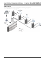
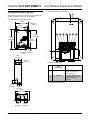
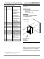
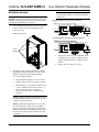
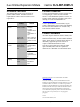
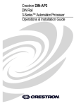
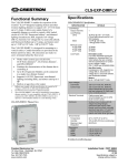
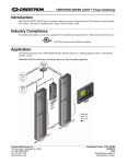
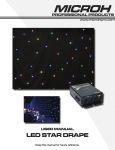
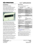
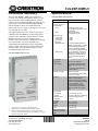
CLS-EXP-DIMFLV
Functional Summary
The CLS-EXP-DIMFLV enables the expansion of
Crestron® iLux® Integrated Lighting System (CLS-C6
Series) and other Crestron lighting dimmers to allow
control of 0-10 volt fluorescent dimming ballasts. It can
also be used to switch non-dimmable loads including
LED, incandescent, MLV, ELV, HID, fluorescent
ballasts, and motors. A single model supports 120, 230, or
277 volt loads up to 16 amps.
Any output channel of the iLux system can be used to
control the CLS-EXP-DIMFLV to dim a fully loaded
circuit. It is also compatible with CLW-Series1 in-wall
dimmers and select CLX-Series lighting control
modules.2 The metal enclosure is designed for mounting
to a vertical surface3 and can be installed in an
environmental air-handling space above a suspended
ceiling. Conduit knockouts are provided on the bottom
and lower sides. All connections are made via screw
terminals behind the front cover.
CLS-EXP-DIMFLV Physical View
Specifications
CLS-EXP-DIMFLV Specifications
SPECIFICATION
Load Ratings
Dimmer Channels
Load Ratings
Lamp
Motor
Minimum Load
at 120 volts
at 230 volts
at 277 volts
Load Types
Dimmable Load
Switch Load
Input Voltages
Line Power
Control Input
1.
2.
3.
CLW-Series device must have a dedicated neutral.
Compatible only with forward-phase dimming modules.
Must be oriented upright, mounted to a vertical surface, with
6 inches (153 mm) minimum spacing above and below for proper
ventilation and heat dissipation.
Crestron Electronics, Inc.
15 Volvo Drive Rockleigh, NJ 07647
Tel: 888.CRESTRON
Fax: 201.767.7576
www.crestron.com
DETAILS
1
16 amps @ 120–277 volts
(70 mA max current sink for 0-10
Vdc ballasts)
1/2 HP @ 120 volts;
1 HP @ 230/277 volts
15 watts
25 watts
30 watts
0-10 Vdc dimmable fluorescent
ballasts, Advance Mark 7 or other
compliant with specifications for
control by dc voltage per ANSI
C82.11:2002 and IEC60929:2006
LED, incandescent, fluorescent,
magnetic low voltage, electronic
low voltage, neon/cold cathode,
high-intensity discharge (HID),
motors
120–277 Vac, 50/60 Hz
120–230 Vac, 50/60 Hz, phase
independent of line power and
load;
Presents a 25 watt load to the
controlling device
Electrical Terminals
Captive screw type;
Accommodates two 22-12 AWG
(0.34-4.0 mm2) wires
Enclosure
Surface mount module with (2)
integral mounting flanges,
galvanized steel with gray matte
powder coat front panel, extruded
aluminum heat sink, 1/2 in
(13 mm) and 3/4 in (20 mm)
conduit knockouts provided on
bottom and lower left and right
sides
Environmental
Temperature
Humidity
Maximum Heat
Dissipation
32° to 104°F (0° to 40°C)
10% to 90% RH (non-condensing)
70 Btu/h at maximum load,
16 amps
Dimensions
Height
Width
Depth
8.82 in (224 mm)
6.39 in (163 mm)
3.18 in (81 mm)
Weight
3.3 lbs (1.5 kg)
Maximum Expansion
Modules per Controller
Output
5
Installation Guide – DOC. 6680B
(2020652)
06.14
Specifications subject to
change without notice.
Crestron CLS-EXP-DIMFLV
iLux Dimmer Expansion Module
Regulatory Compliance
This product is Listed to applicable UL Standards and requirements by Underwriters
Laboratories Inc.
As of the date of manufacture, the CLS-EXP-DIMFLV has been tested and found to
comply with specifications for CE marking.
Federal Communications Commission (FCC) Compliance Statement
This device complies with part 15 of the FCC Rules. Operation is subject to the following
conditions:
(1) This device may not cause harmful interference and (2) this device must accept any
interference received, including interference that may cause undesired operation.
CAUTION: Changes or modifications not expressly approved by the manufacturer
responsible for compliance could void the user’s authority to operate the equipment.
NOTE: This equipment has been tested and found to comply with the limits for a Class B
digital device, pursuant to part 15 of the FCC Rules. These limits are designed to provide
reasonable protection against harmful interference in a residential installation. This
equipment generates, uses and can radiate radio frequency energy and, if not installed and
used in accordance with the instructions, may cause harmful interference to radio
communications. However, there is no guarantee that interference will not occur in a
particular installation. If this equipment does cause harmful interference to radio or
television reception, which can be determined by turning the equipment off and on, the
user is encouraged to try to correct the interference by one or more of the following
measures:
•
Reorient or relocate the receiving antenna
•
Increase the separation between the equipment and receiver
•
Connect the equipment into an outlet on a circuit different from that to which the
receiver is connected
•
Consult the dealer or an experienced radio/TV technician for help
2 • iLux 0-10V Fluorescent Dimmer Expansion Module: CLS-EXP-DIMFLV
Installation Guide – DOC. 6680B
iLux Dimmer Expansion Module
Crestron CLS-EXP-DIMFLV
Application
The following diagram shows several CLS-EXP-DIMFLV modules in a typical application.
CLS-EXP-DIMFLV Modules in a Lighting Application
LA
N
0 - 10 V
Fluorescent Ballast
Non-Dim Fluorescent
Ballast
HID Non-Dim
120 Vac or
230 Vac
Installation Guide – DOC. 6680B
On or Off
iLux 0-10V Fluorescent Dimmer Expansion Module: CLS-EXP-DIMFLV • 3
Crestron CLS-EXP-DIMFLV
Physical Description
iLux Dimmer Expansion Module
CLS-EXP-DIMFLV (Cover Removed)
This section provides information on the connections and
indicators available on the CLS-EXP-DIMFLV.
CLS- EXP-DIMFLV Overall Dimensions
5.79 in
Ø 0.19 in
(148 mm)
(5 mm)
4.99 in
(127 mm)
8.31 in
(212 mm)
8.82 in
(224 mm)
7.31 in
(186 mm)
3.18 in
(81 mm)
0.50 in
Ø 0.25 in (13 mm)
(7 mm)
3.07 in
(78 mm)
Connectors and Indicators
DESCRIPTION
#
CONNECTORS
AND
INDICATORS
1
STATUS
(1) Red LED behind front
panel, illuminates when
load output is on
2
POWER
(1) Green LED behind front
panel, indicates line power
is applied to the HOT
terminal
(Continued on following page)
1.56 in
(40 mm)
2.02 in
(53 mm)
6.39 in
(163 mm)
1.64 in
(42 mm)
1.64 in
(42 mm)
4 • iLux 0-10V Fluorescent Dimmer Expansion Module: CLS-EXP-DIMFLV
Installation Guide – DOC. 6680B
iLux Dimmer Expansion Module
Connectors and Indicators (Continued)
#
CONNECTORS
AND
INDICATORS
DESCRIPTION
3
INPUT–CTRL
(1) Captive screw terminal,1
control input from
CLS(I)-C6 Series,
CLW-DIM Series,2
CLX(I)-DIM Series,
GLX-DIM6, GLXX-2DIM8,
DIN-1DIM4, or
DIN-1DIMU4 dimmers
NOTE: Presents a 25 watt
load to the controlling
dimmer; a maximum of five
CLS-EXP-DIMFLV modules
may be connected to the
controlling dimmer, which
cannot be wired to control
any other loads besides the
CLS-EXP-DIMFLV
modules.
4
INPUT–NEUT
(1) Captive screw terminal,1
neutral connection for
control input
5
OUTPUT–SW OUT
(1) Captive screw terminal,1
switched load output
6
OUTPUT–HOT
(1) Captive screw terminal,1
line power input
7
OUTPUT–NEUT
(1) Captive screw terminal,1
neutral connection for line
power input and load
8
0-10V–(+)
(1) Captive screw terminal,1
dimming control output;
Class 1 or Class 2 wiring
allowed;
Control Voltage: 0-10 Vdc,
70 mA
9
0-10V–(-)
(1) Captive screw terminal,1
dimming control output;
Class 1 or Class 2 wiring
allowed;
Control Voltage: 0-10 Vdc,
70 mA
10
GROUND
(1) 3-terminal chassis
ground bus bar
Crestron CLS-EXP-DIMFLV
Setup
Important Notes
Read before installation.
•
•
Install in accordance with all local and national
electrical codes.
Use 75°C copper wire only.
Installation
Refer to the following diagram when installing a
CLS-EXP-DIMFLV module.
Module Installation
Mounting Surface
CLS-EXP-DIMFLV
Mounting Screw, #8
Qty. 4 Total
(Not Supplied)
NOTE: To prevent potential heat damage to the drywall,
do not mount the CLS-EXP-DIMFLV directly onto
drywall. Mount a piece of 1/2 in (13 mm) minimum thick
plywood between the CLS-EXP-DIMFLV and the
drywall.
NOTE: To ensure proper ventilation, the device must be
installed vertically on a vertical surface. Install device
with 6 inches (153 mm) of clearance from the top and
bottom of the device.
1.
2.
Captive screw terminals accept up to two 22 to 12 AWG (0.34 to
4 mm2) wires per terminal.
CLW-Series device must have a dedicated neutral.
Installation Guide – DOC. 6680B
iLux 0-10V Fluorescent Dimmer Expansion Module: CLS-EXP-DIMFLV • 5
Crestron CLS-EXP-DIMFLV
iLux Dimmer Expansion Module
Hardware Hookup
WARNING: RISK OF SERIOUS PERSONAL
INJURY. Turn off power at the circuit breaker(s) prior to
installation. Installing with power on can result in serious
personal injury and damage to the device.
NOTE: When using a CLW-Series wall dimmer,
the wall dimmer must be wired with a dedicated
neutral wire.
CLS-EXP-DIMFLV Wiring for 0-10 V Dimming
Hot
(120 to 277 Vac )
Neutral
LOAD1
CLS(I)-C6
HOT
NEUTRAL
Neutral
Gray
LOAD2
White
LOAD3
Hot
(120 or 230 Vac )
Black Violet
Use a #2 Phillips screwdriver to remove the cover
screws as shown in the following diagram and
remove the cover.
Black
1.
0-10V Fluorescent
Dimming Ballast
Remove Cover Screws
CLS-EXP-DIMFLV Wiring for Switching Application
Hot
(120 to 277 Vac)
NEUTRAL
2.
LOAD1
CLS(I)-C6
HOT
NEUTRAL
Neutral
Black
Cover
Screws
Black
LOAD2
White
LOAD3
Switched Load
3.
Apply power to the line or load and turn on the
controlling device. The power indicator LED
lights indicating that power is supplied to the
module.
4.
Replace the cover and cover screws.
Depending on the module’s application, select the
appropriate configuration from one of the wiring
diagrams in the next column and connect the
CLS-C6 and load(s) as shown.
•
Wires should be stripped to 7/16 in (12 mm).
•
Tighten terminal screws to 7 in-lbs (0.79 Nm).
•
When wiring a 0-10 V fluorescent dimmer, the
+ and – terminals can be wired as Class 1 or
Class 2. If wired as Class 1, the barrier
between the NEUT and + terminals can be
removed.
NOTE: Dimmer channels controlling one or more
CLS-EXP-DIMFLV modules must not be wired to
control any other type of load.
NOTE: While these diagrams show a CLS-C6 as
the controlling source, other Crestron products
such as CLW-Series wall dimmers (Cresnet® and
infiNET™) and CLX-Series dimming modules can
be used as well. Refer to “Specifications” on page
1 for details.
6 • iLux 0-10V Fluorescent Dimmer Expansion Module: CLS-EXP-DIMFLV
Installation Guide – DOC. 6680B
iLux Dimmer Expansion Module
Problem Solving
The following table provides corrective action for
possible trouble situations. If further assistance is
required, please contact a Crestron customer service
representative.
CLS-EXP-DIMFLV Troubleshooting
TROUBLE
Load does not
turn on.
Load turns on
and off but does
not dim.
POSSIBLE
CAUSE(S)
CORRECTIVE
ACTION
The controlling
dimmer or switch
is not working.
Make sure the
controller is
powered on and is
one of the
compatible dimmers
listed in
“Specifications” on
page 1.
No power is
applied to the
HOT terminal.
Check circuit
breaker. Check that
green power LED
on inside of unit is
lit.
Controlling unit is
either not a
dimmer or has
been set to nondim.
Verify that dimmer is
compatible with the
CLS-EXP-DIMFLV
(refer to
“Specifications” on
page 1).
Crestron CLS-EXP-DIMFLV
Further Inquiries
To locate specific information or resolve questions after
reviewing this guide, contact Crestron's True Blue
Support at 1-888-CRESTRON [1-888-273-7876] or, for
assistance within a particular geographic region, refer to
the listing of Crestron worldwide offices at
www.crestron.com/offices.
To post a question about Crestron products, log onto
Crestron’s Online Help at www.crestron.com/onlinehelp.
First-time users must establish a user account to fully
benefit from all available features.
Future Updates
As Crestron improves functions, adds new features, and
extends the capabilities of the CLS-EXP-DIMFLV,
additional information may be made available as manual
updates. These updates are solely electronic and serve as
intermediary supplements prior to the release of a
complete technical documentation revision.
Check the Crestron website periodically for manual
update availability and its relevance. Updates are
identified as an “Addendum” in the Download column.
Verify that the
controlling channel
has not been
programmed as nondim.
Lights do not dim
properly.
An incompatible
dimmer is being
used.
Make sure that the
dimmer is one of
those listed in
“Specifications” on
page 1.
The specific patents that cover Crestron products are listed at
patents.crestron.com.
Crestron, the Crestron logo, Cresnet, iLux, and infiNET are either
trademarks or registered trademarks of Crestron Electronics, Inc. in the
United States and/or other countries. UL and the UL logo are either
trademarks or registered trademarks of Underwriters Laboratories, Inc.
in the United States and/or other countries. Other trademarks, registered
trademarks, and trade names may be used in this document to refer to
either the entities claiming the marks and names or their products.
Crestron disclaims any proprietary interest in the marks and names of
others. Crestron is not responsible for errors in typography or
photography.
This document was written by the Technical Publications department at
Crestron.
©2014 Crestron Electronics, Inc.
Installation Guide – DOC. 6680B
iLux 0-10V Fluorescent Dimmer Expansion Module: CLS-EXP-DIMFLV • 7
Crestron CLS-EXP-DIMFLV
iLux Dimmer Expansion Module
Return and Warranty Policies
Merchandise Returns / Repair Service
1.
No merchandise may be returned for credit, exchange or service without prior authorization from
Crestron. To obtain warranty service for Crestron products, contact an authorized Crestron dealer.
Only authorized Crestron dealers may contact the factory and request an RMA (Return Merchandise
Authorization) number. Enclose a note specifying the nature of the problem, name and phone number
of contact person, RMA number and return address.
2.
Products may be returned for credit, exchange or service with a Crestron Return Merchandise
Authorization (RMA) number. Authorized returns must be shipped freight prepaid to Crestron,
6 Volvo Drive, Rockleigh, N.J. or its authorized subsidiaries, with RMA number clearly marked on the
outside of all cartons. Shipments arriving freight collect or without an RMA number shall be subject to
refusal. Crestron reserves the right in its sole and absolute discretion to charge a 15% restocking fee
plus shipping costs on any products returned with an RMA.
3.
Return freight charges following repair of items under warranty shall be paid by Crestron, shipping by
standard ground carrier. In the event repairs are found to be non-warranty, return freight costs shall be
paid by the purchaser.
Crestron Limited Warranty
Crestron Electronics, Inc. warrants its products to be free from manufacturing defects in materials and
workmanship under normal use for a period of three (3) years from the date of purchase from Crestron, with the
following exceptions: disk drives and any other moving or rotating mechanical parts, pan/tilt heads and power
supplies are covered for a period of one (1) year; touch screen display and overlay components are covered for
90 days; batteries and incandescent lamps are not covered.
This warranty extends to products purchased directly from Crestron or an authorized Crestron dealer.
Purchasers should inquire of the dealer regarding the nature and extent of the dealer's warranty, if any.
Crestron shall not be liable to honor the terms of this warranty if the product has been used in any application
other than that for which it was intended or if it has been subjected to misuse, accidental damage, modification
or improper installation procedures. Furthermore, this warranty does not cover any product that has had the
serial number altered, defaced or removed.
This warranty shall be the sole and exclusive remedy to the original purchaser. In no event shall Crestron be
liable for incidental or consequential damages of any kind (property or economic damages inclusive) arising
from the sale or use of this equipment. Crestron is not liable for any claim made by a third party or made by the
purchaser for a third party.
Crestron shall, at its option, repair or replace any product found defective, without charge for parts or labor.
Repaired or replaced equipment and parts supplied under this warranty shall be covered only by the unexpired
portion of the warranty.
Except as expressly set forth in this warranty, Crestron makes no other warranties, expressed or implied, nor
authorizes any other party to offer any warranty, including any implied warranties of merchantability or fitness
for a particular purpose. Any implied warranties that may be imposed by law are limited to the terms of this
limited warranty. This warranty statement supersedes all previous warranties.
8 • iLux 0-10V Fluorescent Dimmer Expansion Module: CLS-EXP-DIMFLV
Installation Guide – DOC. 6680B