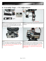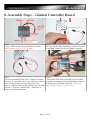
1
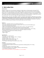
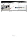
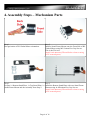
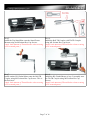
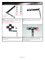
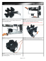
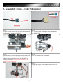
Senrigan-GP-45 Brushless Gimbal
Instruction Manual v1.1
Page 1 of 16
Contents
1. Introduction.........................................................................................................................................................3
2. Check List............................................................................................................................................................4
3. Equipment Required For Assembly....................................................................................................................5
4. Assembly Steps – Mechanism Parts....................................................................................................................6
5. Assembly Steps – IMU Mounting.....................................................................................................................10
6. Assembly Steps – CG Adjustment.....................................................................................................................11
7. Assembly Steps – Install with Landing Gear....................................................................................................12
8. Assembly Steps – Gimbal Controller Board.....................................................................................................13
9. Power On Steps.................................................................................................................................................15
10. Troubleshooting...............................................................................................................................................16
End Of Manual......................................................................................................................................................16
Page 2 of 16
1. Introduction
Introduction:
Brushless Gimbal is the next generation technology for high quality aerial photography. Senrigan GP-45
Brushless Gimbal is driven directly with two Brushless Motors for two axis movement roll and tilt without
gears or belts. The main advantages of this design compared to traditional actuators (servos) are the Brushless
Gimbals have no backlash in the gear/belt, and it provides the instantaneous response to the disturbance. Due to
lack of gears/ belts, this new Brushless Gimbal is extrenely easy to install and with low weight which is perfect
for aerial activities. The lower the weight, the longer the flying time you can achieve.
Differ than others, the motors and Gimbal Controller of Senrigan GP-45 Brushless Gimbal have been well test
and tuned of the PID parameter for GoPro Cameras in the factory before selling. So no worries about the setting
or PID tuning of the Brushless Gimbal. Furthermore, with an Advanced Landing Gear Set you will be able to
install the Senrigan GP-45 Brushless Gimbal onto DJIF450/ 550/ other Multicopters effortlessly. Last but not
the least, a detailed instruction manual could be downloaded freely in the internet.
Features:
-Direct drive of Brushless Motors for both Roll and Tilt axis.
-Advanced Landing Gear Set (with battery mount) which is best fit on F450/550 Multicopters.
-Simple and strong Mechanism Design
-Made of CNC Metal Parts and full Carbon Fiber Frames which is super light and strong.
-Super Steady Performance with high quality Rubber Tension Damper Balls.
-High Quality Brushless Gimbal Controller (Pre-programmed) with High Quality CNC Casing.
-Well test and PID parameter tuned by the factory for GoPro/ Similar size cameras.
-Controllable Tilt Axis Movement with Max. 90 Degree
-Easy to install and use.
-Ligh in weight.
Specification:
-Movement: 2-axis, Roll and Tilt
-Controllable axis: Tilt +-60 Degree, Roll +-80 Degree
-Working Voltage: 3S 11.1V Lipo
-Gimbal Controller Weight (with casing): 47g
-Brushless Gimbal with Controller: 240g
-Total Weight with Landing Gear(without camera): 506g
Included:
1x Senrigan GP-45 Brushless Gimbal
1x Senrigan Brushless Gimbal Controller(Pre-programmed) with High Quality CNC Casing
1x IMU Unit
8x High Quality Rubber Tension Damper Balls
1x Advanced Landing Gear Set with Battery Mount (For DJI F450/550)
1x Tilt and Roll Controlling Connector
(Please be noted that GoPro, Aircraft and Battery are not included.)
Page 3 of 16
2. Check List
Please Check the Follow parts.
BL Gimbal Controller
1pcs
IMU Unit
1pcs
BL Gimbal Motor 2208
2pcs
CNC Metal Parts:
A: Tilt TR Coupler – 1pcs
B: Stand Frame Mount – 2pcs
C: Spine Mount – 1pcs
D: Roll TR Coupler – 1pcs
E: Boom Mount – 2pcs
Carbon Fiber Plates:
F: Top Mounting Plate – 1pcs
G: Bottom Mounting Plate – 1pcs
H: Bottom Stand Plate – 1pcs
I: Top Stand Plate – 1pcs
Coupler Carbon Boom
1pcs
Rubber Tension Damper Balls
8pcs
Screw Pack
1pcs
Tilt and Roll Controlling Connector
1pcs
Advanced Landing Gear Set
1pcs
Page 4 of 16
3. Equipment Required For Assembly
1pcs Gopro Camera (v1,2 or 3)
1pcs 3S 11.1V Lipo 800mAh (or above) or 1pcs JST to 3S Lipo Balance
Connector.
(Used to supply power to the Gimbal.)
Page 5 of 16
4. Assembly Steps – Mechanism Parts
Step 1.
Recognization of BL Gimbal Motor oriantation.
Step 2.
Install a Stand Frame Mount onto the Front Side of BL
Gimbal Motor using M2.5x6mm Hex Cap Screws.
This is the Tilt Axis.
(Apply little amount of Thread Locker when securing
screw to metal parts.)
Step 3.
Sep 4.
Prepare 1x Bottom Stand Plate, 1x Top Stand Plate, 1x Install the Bottom Stand Plate with two Stand Frame
Stand Frame Mount and the Assembly from Step 2.
Mounts using 4x M2x6mm Hex Cap Screws.
(Apply little amount of Thread Locker when securing
screw to metal parts.)
Page 6 of 16
Step 5.
Install the Top Stand Plate onto the Stand Frame
Mounts using 4x M2x6mm Hex Cap Screws.
(Apply little amount of Thread Locker when securing
screw to metal parts.)
Step 6.
Install the Roll TR Coupler with Tilt TR Coupler
using M2.5x6mm Hex Cap Screw.
(Apply little amount of Thread Locker when securing
screw to metal parts.)
Step 7.
Install another BL Gimbal Motor onto the Roll TR
Coupler using M2.5x6mm Hex Cap Screws. This is
the Roll Axis.
(Apply little amount of Thread Locker when securing
screw to metal parts.)
Step 8.
Install the BL Gimbal Motor of step 5 Assembly onto
the Tilt TR Coupler using M2.5x6mm Hex Cap
Screws.
(Apply little amount of Thread Locker when securing
screw to metal parts.)
Page 7 of 16
Step 9.
Install the Coupler Carbon Boom with Spine Mount
using M2x6mm Hex Cap Screw.
(Apply little amount of Thread Locker when securing
screw to metal parts.)
Step 10.
Insert two Boom Mounts onto the Coupler Carbon
Boom.
Step 11.
Prepare the Assembly from step 10 and the Bottom
Mounting Plate.
Step 12.
Install the Bottom Mounting Plate onto the Boom
Mounts using M2.6x18mm Hex Cap Screws with
M2.5 Self Lock Nuts.
Page 8 of 16
Step 13.
Insert 8pcs Rubber Tension Damper Balls onto the
Bottom Mounting Plate.
Step 14.
Install the Spine Mount onto the Roll Axis BL Gimbal
Motor using M2.5x6mm Hex Cap Screws.
(Apply little amount of Thread Locker when securing
screw to metal parts.)
Step 15.
Close view of step 14.
Step 16.
Senrigan GP-45 Gimbal mechanism assembly view.
Step 17.
Insert 8pcs Rubber Tension Damper Balls onto the
Top Mounting Plate.
Page 9 of 16
5. Assembly Steps – IMU Mounting
Step 1.
Prepare the IMU Unit. There is a specific orientation
requirement to mount the IMU Unit.
Step 2.
Use a double-sided foam tape to stick onto the back
side of IMU Unit.
Step 3.
Step 4.
Stick the IMU Unit onto the Bottom Stand Plate using Close view for the IMU installation.
double-sided foam tape. Check the double faced
adhesive tape regularly to ensure that the IMU is
securely positioned. (Ensure the orientation of the
IMU is installed correctly.)
Step 5.
Arrange the cables of the Tilt BL Gimbal Motor and
Roll BL Gimbal Motor with a zip tie.
Page 10 of 16
6. Assembly Steps – CG Adjustment
Step 1.
Release the Top Stand Plate and prepare your own
GoPro or cameras with similar weight. Use doublesided foam tape to secure the GoPro in the center of
the Bottom Stand Plate.
Step 2.
Adjust the position of the Camera to the center axis of
Tilt Motor.
Step 3.
Secure the GoPro by installing the Top Stand Plate
back to the Stand Frame Mount using 4pcs M2x6mm
Screws. (Apply little amount of Thread Locker when
securing screw to metal parts.)
Step 4.
Adjust the balance point of the Roll Axis by loosing
two M2.5x6mm Screws on the Roll Motor as to move
the Roll TR Coupler to left or right side. (Make sure
the GoPro stay level which indicate the correct CG
position. This is very important for steady operation
of the Gimbal.)
Page 11 of 16
7. Assembly Steps – Install with Landing Gear
Step 1.
Install the Advanced Landing Gear according to the
above photo. (Apply little amount of Thread Locker
when securing screw to metal parts.)
Step 2.
Mount the Gimbal Assembly onto the FPV Mount
Plate using 4pcs M3x 10mm Hex Cap Screws with
M3 Self-Lock Nuts.
Step 3.
Finished Gimbal Assembly with the Advanced
Landing Gear.
Step 4.
Illustration to install with DJI F550 Hexacopter.
Page 12 of 16
8. Assembly Steps – Gimbal Controller Board
Step 1.
Usage of different ports on the Gimbal Controller.
(Best working power is 11.1V 3S Lipo.)
Step 2.
Insert the Tilt and Roll Controlling Connector into the
Til and Roll Control Port on the Gimbal Controller.
Step 3.
Tilt Axis is controlled with 2-wire connector, and the
Roll Axis is controlled with 1-wire connector. Connect
these connectors into two free channels of your
receiver. Adjust the limit of the channels as to limit the
Tilt into +-60 degree, and Roll into +-80 degree or
bellow for stable performance.
Step 4.
Connect IMU Unit cable to the IMU port of Gimbal
Controller. And connect Tilt and Roll Motor cables to
the motor ports of Gimbal Controller. (Follow the
exact direction for for all connections.)
Page 13 of 16
Step 5.
Secure the Gimbal Controller on the landing gear or
on the bottom frame of your F450/ F550 Multicopter
with tap Adhesive Tapes, Zip Tie or double-sided
foam tape.
Step 6.
Bottom view of Gimbal Controller mounting on the
landing gear. Connect the Tilt or Roll Axis Manual
Control Connector to any free channels of your
Receiver as to control the Tilt Axis manually. The
Gimbal is recommended to power with 11.1V 3S Lipo
Battery with JST connector.
Page 14 of 16
9. Power On Steps
Before Power On the Gimbal:
1. Please check the polarity on IMU cable making sure the vcc and gnd are connected to correct pins.
2. Make sure the IMU is facing down when installing. Refer to IMU Mounting section.
3. We suggest to use 3s battery for GoPro or similar size cameras.
4. Double check the battery polarity before plugged in.
5. The Brushless Gimbal Controller is preset to plug-n-play with GoPro camera. There is no
additional tuning needed.
Follow the following sequencies to power on your Senrigan-GP-45 Brushless Gimbal correctly.
Step 1.
Prepare a 2-3S 800mAh (recommended to use with 3S 11.1V) Lipo Battery which must has JST connector, or
you can get the supply voltage from your 3S Lipo flying battery using a JST to 3S Balance Connector(not
included).
Step 2.
Place the Senrigan-GP-45 Gimbal Assembly on the ground and keep it steady during the starting process.
Step 3.
Connect the Battery to the Power Cable of the Gimbal (JST connector) and wait for around 15 seconds. IMU is
now initialing.(Do not move the Gimbal during the initialisation process, otherwise the Gimbal will fail to
start!) After the Initialization Process, the Tilt and Roll Motors will move slowly to the center position. The
camera will now be stayed in the level position.
If the Gimbal fail to start normally, reboot the power and try again. (Remember never move the Gimbal during
the Initialization Process.)
Step 4.
Ready to go.
Page 15 of 16
10. Troubleshooting
Q1: Why does the gimbal not stabilize the camera?
A: Please check the battery voltage and if the LED is lit.
Q2: Why is the gimbal not stabilizing the camera in right direction?
A: Please refer to installation and make sure the IMU Unit is installed at right orientation and the motors
are connected to right pins.
Q3: Why is the gimbal shaking?
A: Usually it is caused be wrong IMU facing, please make sure it is facing down. Refer to IMU Mounting
section.
Q4. Why is the captured video shaking?
A: Please ensure your Aircraft is well turned with minimum vibration before mounting the Gimbal. Double
check the CG of the Camera, make sure the Camera is well balanced. Refer to CG Adjustment section.
Q4: Do I need to upgrade to latest version of firmware or adjust any parameters?
A: For this Basic Version, it is not necessary to upgrade the firmware or adjust any parameters unless further
instruction is given. The Brushless Gimbal Controller is preset to plug-n-play with GoPro or simlar size camera.
The gimbal controller is preset to give the best performance.
Q5: Where can I get more help for this product?
A: Please contact our distributors for warranty and customer service.
# Report any mistakes, please email to:
[email protected]
Related Videos could be found on: http://www.youtube.com/user/alwarerc
End Of Manual
Page 16 of 16