1
EN
Service Bulletin
SB-2-858-B
Replaces SB-2-858-A
Technical Bulletin
Compact MINI range of Gravity Spray Guns
for spot repairs and small areas
Page 2
SB-2-858-B
Table of Contents
TopicPage
EC Declaration of Conformity. . . . . . . . . . . . . . . . . . . . . . . . . . . . . . . . . . . . . . . . . . . . . . . . . 3
Part Numbers . . . . . . . . . . . . . . . . . . . . . . . . . . . . . . . . . . . . . . . . . . . . . . . . . . . . . . . . . . . . . 3
Operational Description . . . . . . . . . . . . . . . . . . . . . . . . . . . . . . . . . . . . . . . . . . . . . . . . . . . . . 3
Kit contents . . . . . . . . . . . . . . . . . . . . . . . . . . . . . . . . . . . . . . . . . . . . . . . . . . . . . . . . . . . . . . . 4
Construction Features . . . . . . . . . . . . . . . . . . . . . . . . . . . . . . . . . . . . . . . . . . . . . . . . . . . . . . 4
Materials of Construction. . . . . . . . . . . . . . . . . . . . . . . . . . . . . . . . . . . . . . . . . . . . . . . . . . . . 4
Specifications & Technical Data . . . . . . . . . . . . . . . . . . . . . . . . . . . . . . . . . . . . . . . . . . . . . . 4
Safety Precautions . . . . . . . . . . . . . . . . . . . . . . . . . . . . . . . . . . . . . . . . . . . . . . . . . . . . . . . . . 5
Parts List . . . . . . . . . . . . . . . . . . . . . . . . . . . . . . . . . . . . . . . . . . . . . . . . . . . . . . . . . . . . . . . . . 6
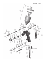
Exploded Parts View. . . . . . . . . . . . . . . . . . . . . . . . . . . . . . . . . . . . . . . . . . . . . . . . . . . . . . . . 7
Installation, Operation, Preventive Maintenance & Cleaning . . . . . . . . . . . . . . . . . . . . . . . 8
Parts Replacement/Maintenance . . . . . . . . . . . . . . . . . . . . . . . . . . . . . . . . . . . . . . . . . . . . . . 9
A. Servicing Air Valve . . . . . . . . . . . . . . . . . . . . . . . . . . . . . . . . . . . . . . . . . . . . . . . . . . . 9
B. Replacing Air Valve . . . . . . . . . . . . . . . . . . . . . . . . . . . . . . . . . . . . . . . . . . . . . . . . . . . 10
C. Needle Packing, Fluid Insert, Spreader Valve Assembly . . . . . . . . . . . . . . . . . . . . . 11
D. Spray Head Seal . . . . . . . . . . . . . . . . . . . . . . . . . . . . . . . . . . . . . . . . . . . . . . . . . . . . . 12
E. Chart 1 – Air Caps, Chart 2 – Fluid Nozzles & Fluid Needles . . . . . . . . . . . . . . . . . . 13
Troubleshooting Possible Problems in Operation . . . . . . . . . . . . . . . . . . . . . . . . . . . . . . . . 14
Accessories . . . . . . . . . . . . . . . . . . . . . . . . . . . . . . . . . . . . . . . . . . . . . . . . . . . . . . . . . . . . . . . 16
Warranty. . . . . . . . . . . . . . . . . . . . . . . . . . . . . . . . . . . . . . . . . . . . . . . . . . . . . . . . . . . . . . . . . . 16
SB-2-858-B
Page 3
EC Declaration of Conformity
We, Finishing Brands UK, Ringwood Rd, Bournemouth, Dorset, BH11 9LH, UK, as the manufacturer
of the Spray gun model Compact MINI, declare, under our sole responsibility, that the equipment
to which this document relates is in conformity with the following standards or other normative
documents:
BS EN 292-1 PARTS 1 & 2: 1991, BS EN 1953: 1999; and thereby conform to the protection
requirements of Council Directive 98/37/EEC relating to Machinery Safety Directive, and;
EN 13463-1:2001, council Directive 94/9/EC relating to Equipment and Protective Systems intended
for use in Potentially Explosive Atmospheres protection level II 2 G X. This product also complies with
the requirements of the EPA guidelines, PG6/34.
Dave Smith, General Manager
1st Dec 2008
Finishing Brands reserve the right to modify equipment specification without prior notice.
Part Numbers
The ordering codes for the Compact MINI Spray Gun are:
COMM-HS1-10 Compact MINI HVLP 1.0
COMM-HS1-12 Compact MINI HVLP 1.2
COMM-TS1-10 Compact MINI Trans-Tech® 1.0
COMM-TS1-12 Compact MINI Trans-Tech® 1.2
COMM-RS1-08 Compact MINI Round Spray Trans-Tech® 0.8
Operational Description
This Compact MINI Spray Gun is a professional quality gun designed with both high volume, low pressure
(HVLP) technology or Trans-Tech® technology. HVLP Technology reduces overspray and limits air cap
pressure to 0.7 bar (10 psi) (complies with rules issued by SCAQMD and other air quality authorities). TransTech technology, will obtain transfer efficiencies above 65%.
IMPORTANT: These Sprayguns are suitable for use with both waterbased and solvent based coating
materials. These guns are not designed for use with highly corrosive and/or abrasive materials and if
used with such materials it must be expected that the need for cleaning and/or replacement of parts will
be increased. If there is any doubt regarding the suitability of a specific material, contact your DeVilbiss
Distributor or DeVilbiss direct.
NOTE: This gun is not to be used with halogenated hydrocarbon solvents or cleaning agents such as
1,1,1,-Trichloroethane or methylene chloride. These solvents can react with the aluminium components
used in this gun and cup. The reaction can become violent and lead to an equipment explosion.
Page 4
SB-2-858-B
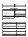
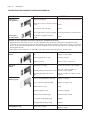
KIT CONTENTS (ALL MODELS)
1
Compact MINI Gravity Feed Spraygun
1
Torx/Flat Blade Screwdriver
1
Compact MINI Gravity Feed Cup
1
Small Cleaning Brush
1
Cup Filter
1
Large Cleaning Brush
1
Funnel
1
Service Bulletin
1
Spanner (6mm hex and 10mm A/F)
Construction Features
1
Air Cap
(nickel plated brass for long durability)
10
Fan Air Adjustment
(stepless regulation for fan to round spray)
2
Air Cap Retaining Ring
(allows easy rotation of air cap)
11
Fluid Adjustment
(stepless regulation of fluid volume)
3
Fluid Nozzle
4
Fluid Needle
(grooved stem for easy removal)
12
Anodized, forged aluminium gun body
(ergonomic, good looking & durable, easy
to clean)
5
Fluid Inlet (7/16” – 14 UNC thread) – accepts
DeVilbiss SRI cup systems
13
125cc Acetal Cup (easy clean, anti-static)
14
Cup Lid with Drip Free Vent (avoid drips)
6
Air Inlet
(universal thread, accepts G 1/4 & 1/4 NPS)
15
Air Valve (design offers low pull force & low
pressure drop)
7
Self Adjusting Needle Packing
(for trouble free operation)
16
Gun acceptable for waterborne and solvent
borne applications
8
Trigger (ergonomic for comfort)
9
Trigger Stud & Screw
(easy replacement design)
Materials of Construction
Gun Body
Anodized aluminium
Air Cap
Nickel plated brass
Fluid Nozzle, Fluid Needle, Fluid Inlet, Trigger Stud
Stainless steel
Springs, Clips, Screws
Stainless steel
Seals, Gaskets
Solvent resistant
Trigger
Chrome plated steel
Air Inlet, Body Bushing, Spreader Valve Body, Air Valve Nut,
Air Cap Retaining Ring, Knobs
Chrome plated brass
Air Valve Assembly
Stainless steel, HPDE
Specifications & Technical Data
Air Supply Connection
Universal 1/4" BSP and 1/4" NPS male
Maximum Static Air Inlet Pressure
P1 = 175 psi (12 bar)
Nominal Gun Air Inlet Pressure for HVLP (HS1) and
Trans-Tech® (TS1 & RS1) with gun triggered
29 psi (2.0 bar)
Fluid Supply Connection
7/16 – 14 UNC
Service Temperature
32 to 104°F (0 to 40°C)
Gun Weight ( gun only)
(with cup)
15.0 oz (425 g)
17.1 oz (485 g)
SB-2-858-B
Page 5
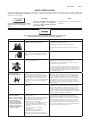
SAFETY PRECAUTIONS
This manual contains information that is important for you to know and understand. This information relates to USER SAFETY and
PREVENTING EQUIPMENT PROBLEMS. To help you recognize this information, we use the following symbols. Please pay particular
attention to these sections.
Important safety information – A hazard
that may cause serious injury or loss
of life.
CAUTION
NOTE
Important information that tells how
to prevent damage to equipment,
or how to avoid a situation that may
cause minor injury.
Information that you should pay special
attention to.
The following hazards may occur during the normal use of this equipment.
Please read the following chart before using this equipment.
HAZARD
Fire
CAUSE
Solvent and coatings can be highly flammable or
combustible especially when sprayed.
SAFEGUARDS
Adequate exhaust must be provided to keep air free of
accumulations of flammable vapors.
Smoking must never be allowed in the spray area.
Fire extinguishing equipment must be present in the spray
area.
Solvent Spray
During use and while cleaning and flushing,
solvents can be forcefully expelled from fluid
and air passages. Some solvents can cause eye
injury.
Wear eye protection.
Inhaling Toxic Substances
Certain materials may be harmful if inhaled, or if
there is contact with the skin.
Follow the requirements of the Material Safety Data Sheet
supplied by your coating material manufacturer.
Adequate exhaust must be provided to keep the air free of
accumulations of toxic materials.
Use a mask or respirator whenever there is a chance of inhaling sprayed materials. The mask must be compatible with the
material being sprayed and its concentration. Equipment must
be as prescribed by an industrial hygienist or safety expert,
and be NIOSH approved.
Explosion Hazard Incompatible Materials
Halogenated hydrocarbon solvents - for
example; methylene chloride and 1,1,1, Trichloroethane are not chemically compatible
with the aluminum that might be used in many
system components. The chemical reaction
caused by these solvents reacting with aluminum
can become violent and lead to an equipment
explosion.
Guns with stainless steel internal passageways may be used
with these solvents. However, aluminum is widely used in
other spray application equipment - such as material pumps,
regulators, valves, and this gun and cup. Check all equipment items before use and make sure they can also be used
safely with these solvents. Read the label or data sheet for
the material you intend to spray. If in doubt as to whether or
not a coating or cleaning material is compatible, contact your
material supplier.
General Safety
Improper operation or maintenance of
equipment.
Operators should be given adequate training in the safe use
and maintenance of the equipment (in accordance with the
requirements of NFPA-33, Chapter 15). Users must comply
with all local and national codes of practice and insurance
company requirements governing ventilation, fire precautions,
operation, maintenance, and housekeeping. These are OSHA
Sections 1910.94 and 1910.107 and NFPA-33.
Cumulative Trauma
Disorders ("CTD's")
Use of hand tools may cause cumulative trauma
disorders ("CTD's").
Pain, tingling, or numbness in the shoulder, forearm, wrist,
hands, or fingers, especially during the night, may be
early symptoms of a CTD. Do not ignore them. Should you
experience any such symptoms, see a physician immediately.
Other early symptoms may include vague discomfort in the
hand, loss of manual dexterity, and nonspecific pain in the
arm. Ignoring early symptoms and continued repetitive use of
the arm, wrist, and hand can lead to serious disability. Risk is
reduced by avoiding or lessening factors 1-7.
CTD's, or musculoskeletal
disorders, involve damage
to the hands, wrists,
elbows, shoulders, neck,
and back. Carpal tunnel
syndrome and tendonitis
(such as tennis elbow or
rotator cuff syndrome) are
examples of CTD's.
CTD's, when using hand tools, tend to affect the
upper extremities. Factors which may increase
the risk of developing a CTD include:
1. High frequency of the activity.
2. Excessive force, such as gripping, pinching,
or pressing with the hands and fingers.
3. Extreme or awkward finger, wrist, or arm
positions.
4. Excessive duration of the activity.
5. Tool vibration.
6. Repeated pressure on a body part.
7. Working in cold temperatures.
CTD's can also be caused by such activities as
sewing, golf, tennis, and bowling, to name a few.
Page 6
SB-2-858-B
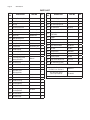
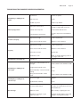
Parts List
REF.
NO.
DESCRIPTION
PART NO.
QTY.
REF.
NO.
DESCRIPTION
PART NO.
QTY.
1
Air Cap Retaining Ring
1
32
Air Valve Poppet
1
2
Slip Ring
1
33
Air Valve Spring
1
3
Air Cap
1
34
Air Valve Spring Pad
1
5
Retaining Ring Seal
1
35
Air Valve Seal
SN-34-K5
1
6
Air Cap & Ring
See chart 1, p13
1
36
Air Valve Assembly
SN-402-K
1
8
Fluid Nozzle
See chart 2, p13
1
37*
1
9
Separator
COMM-2-K5
1
Trigger Stud Screw
(T20 TORX)
12*
Body Bushing Seal
1
38
Trigger
1
13
Body Bushing
1
39*
Trigger Stud
1
14
Body Bushing & Seal
SN-6-K
1
40
Trigger, Stud & Screw Kit
SN-42-K
1
15
Fluid Needle
See chart 2, p13
1
41
Stud and Screw Kit
SN-405-K5
1
16*
Needle Spring
1
42
Air Inlet
SN-40-K
1
17*
Needle Spring Pad
1
44
Airflow Valve
PRO-404-K
1
18
Fluid Adjusting Knob
1
45
Circlip
51
Gravity Cup Kit
SRI-510
1
19
Fluid Adjusting Knob,
Spring & Pad Kit
52
Drip Check Lid (kit of 5)
GFC-2-K5
1
20*
Retaining Clip
1
56
Air Valve Service Tool
21
Spreader Valve Body
1
22*
Spreader Valve Seal
2
23
Spreader Valve
Adjusting Knob
1
24*
Valve Pin
1
25
Spreader Valve Assembly
26*
Needle Packing
1
27*
Packing Spring
1
28
Packing Nut
1
29
Packing, Spring &
Packing Nut Kit
30
Air Valve Body
31
Air Valve Cage
PRO-3-K
COMM-401-K
SN-404-K
1
1
1
1
1
1
SERVICE Parts
Spray Gun Repair Kit
(includes items marked *)
PRO-415-1
Seal & Pin Kit, kit of 5
(items 20, 22 and 24)
GTI-428-K5
For accessories, see page 16
SB-2-858-B
Page 7
Page 8
SB-2-858-B
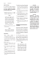
INSTALLATION
For maximum transfer efficiency,
do not use more pressure than is
necessary to atomize the material
being applied. NOTE: when using the
HS1, HVLP setup do not exceed 29.0
psi (2.0 bar) inlet pressure.
1. Connect the gun to a clean,
moisture and oil free air supply
using a conductive hose.
NOTE
11. The pattern size can be reduced
by turning spreader valve knob
(23) clockwise.
12. Hold gun perpendicular to surface
being sprayed. Arcing or tilting
may result in uneven coating.
13. The recommended spray distance
is 3-6 in (75-150 mm).
Install an air gauge at the
gun handle. When gun is
triggered on, adjust regulated
pressure to 29.0 psi (2.0 bar).
Do not use more pressure
than is necessary to atomize
the material being applied.
Excess pressure will create
additional overspray and
reduce transfer efficiency.
14. Spray edges first. Overlap each
stroke a minimum of 75%. Move
gun at a constant speed.
15. Always turn off air supply and
relieve pressure when gun is not
in use.
2. Attach the gravity feed cup to the
material inlet.
NOTE
Before using the gun, flush
it with solvent to ensure that
the fluid passages are clean.
OPERATION
1. Mix
coating
material
manufacturer’s instructions.
10. If finish is too wet, reduce fluid
flow by turning fluid adjusting
knob (18) clockwise. If atomization
is too coarse, increase inlet air
pressure. If too fine, reduce inlet
pressure.
to
2. If required, fit the filter in the cup
or use the funnel with a paper filter.
3. Fill the cup to no more than 1/2
inch from the top of the cup. DO
NOT OVERFILL.
4. Attach Cup Lid.
5. Turn fluid adjusting knob (18)
clockwise to prevent fluid needle
movement.
6. Turn spreader valve adjusting knob
(23) counter clockwise to fully
open.
7. Adjust inlet air pressure to 29.0 psi
(2.0 bar).
8. Turn fluid adjusting knob counter
clockwise until first thread shows.
9. Test spray. If the finish is too dry,
reduce airflow by reducing air inlet
pressure.
PREVENTIVE MAINTENANCE &
CLEANING
To clean air cap and fluid nozzle,
brush exterior with a stiff bristle
brush. If necessary to clean cap holes,
use a broom straw or toothpick if
possible. If a wire or hard instrument
is used, extreme care must be used
to prevent scratching or burring of
the holes which will cause a distorted
spray pattern.
To clean fluid passages, remove
excess material from cup, then flush
with gun wash solution. Wipe the
gun exterior with a dampened cloth.
Never completely immerse in any
solvent or cleaning solutions as this
is detrimental to the lubricants and
life of the spray gun.
NOTE
When replacing the fluid
nozzle or fluid needle, replace
both at the same time. Using
worn parts can cause fluid
leakage. See page 13, Chart
2. Also, replace the needle
packing at this time. Torque
the fluid nozzle to 70 in-lbs
(8 Nm). Do not over tighten.
CAUTION
To prevent damage to fluid
nozzle (8) or fluid needle
(15), be sure to either 1) pull
the trigger and hold while
tightening or loosening the
fluid nozzle, or 2) remove
fluid adjusting knob (18)
to relieve spring pressure
against needle collar.
CAUTION
IMPORTANT — the Gravity
cup is made from special
anti-static materials, but
it still important to avoid
generating static charges.
The Cup must not be cleaned
or rubbed with a dry cloth
or paper. It is possible to
generate a static charge by
rubbing which, if discharged
to an grounded object could
create an incendive spark
and cause solvent vapors to
ignite. Only use a dampened
cloth or antistatic wipes if
manual cleaning is required
within a hazardous area.
SB-2-858-B
Parts Replacement/Maintenance
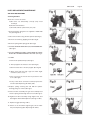
AIR VALVE INSTRUCTIONS
Servicing Air Valve
Reasons to service air valve:
A) Air valve not functioning correctly (may need
cleaning).
B) Routine maintenance.
C) Air leaks (advise replacement, see p10)
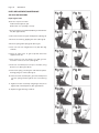
1. Remove trigger using the tool supplied or TORX T20
key. (See fig 1 & 2)
2. Unscrew air valve using 14 mm spanner. (See fig 3)
3. Remove air valve by gripping stem. (See fig 4)
4. Remove spring with spring pad. (See fig 5)
5. DO NOT REMOVE REAR SEAL (35) FROM GUN BODY.
(See fig 6)
6. DO NOT REMOVE PLASTIC CAGE FROM AIR VALVE
BODY AS THIS MAY DAMAGE THE CAGE. (See fig 7)
7. CLEAN
a. Remove all paint build up. (See fig 8)
b. The 4 poppet holes must be clear. (See fig 9)
c. Stem must be free to float in poppet. (See fig 10)
d. Stem must slide through cage bore with slight
resistance (due to seal).
e. Rear seal must look clean and in position in the
bore. (See fig 6)
f. If any of the above cannot be rectified, replace the
air valve (See Replacing Air Valve p10).
8. Replace spring ensuring the end with the plastic
bearing pad goes in first. (See fig 5)
9. Insert air valve assembly into gun and carefully feed
over the spring and through the rear seal. (See fig 11)
10. Tighten air valve assembly using fingers first, and
then tighten with 14mm Spanner. (See figs 12 & 3)
11. Replace trigger. (See figs 2 & 1)
12. If there is an air leak through the gun, the air valve
may need replacing (See Replacing Air Valve).
Page 9
Page 10
SB-2-858-B
Parts Replacement/Maintenance
AIR VALVE INSTRUCTIONS
Replacing Air Valve
Reasons to replace air valve:
A) Air leak through the gun.
B) Air valve not operating correctly.
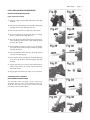
1. Remove trigger using TORX (T20) key provided in the
kit. (See figs 13 & 14)
2. Unscrew air valve using 14 mm Spanner. (See fig 15)
3. Remove air valve by gripping the stem. (See fig 16)
4. Remove spring with spring pad. (See fig 17)
5. Hook out rear seal using Service Tool (56). (See figs
18 & 19)
6. Clean air valve bores in gun body with the brush
supplied in the kit.
7. Place new rear seal onto Service tool (56); grooves
must fit in service tool form. (See fig 20)
8. Push rear seal firmly into hole up to shoulder, using
Service tool. (See figs 21 & 22)
9. Insert new spring, ensuring the end with the plastic
bearing pad goes in first. (See fig 17)
10. Insert air valve assembly into gun and carefully feed
over the spring and through the rear seal. (See fig
23)
11. Tighten air valve assembly using fingers first, then
tighten with 14 mm Spanner. (See figs 24 & 15)
12. Replace trigger. (See figs 14 & 13)
SB-2-858-B
Parts Replacement/Maintenance
NEEDLE PACKING INSTRUCTIONS
Replacing Needle Packing
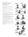
13. Remove trigger using TORX (T20) driver. (See figs
25 & 26)
14. Remove fluid adjusting knob and needle spring with
spring pad from gun. (See figs 27 & 28)
15. Remove fluid needle from gun body. (See fig 29)
16. Loosen and remove packing nut using a straight
blade screwdriver. (See figs 30 & 31)
17. Discard old packing and packing spring if replacing.
Clean packing if reusing. Also clean packing spring
and nut. (See fig 32).
18. Re-assemble the packing, (See fig 32). Assemble
into gunbody by hand (see fig 33) and then tighten.
(See figs 30 and 31)
19. Insert fluid needle all the way into gun body seating
in fluid nozzle (See fig 34).
20. Insert needle spring, spring pad, and fluid adjusting
knob. (See figs 28 & 27). Reinstall trigger. (See figs
25 & 26).
21. Trigger gun fully and screw in fluid adjusting knob
until it stops. Back it off 3 turns and gun will have
full needle travel.
22. Trigger gun several times to verify correct operation.
SPREADER VALVE ASSEMBLY
REPLACEMENT/MAINTENANCE
The spreader valve assembly can be replaced if
damaged. Remove using 14 mm Spanner (See figs
35 & 36). The internal seal can be replaced and is
included in the Gun Rebuild Kit.
Page 11
Page 12
SB-2-858-B
Parts Replacement/Maintenance
SEPARATOR SEAL INSTRUCTIONS
Replacing Separator Seal
1. Remove air cap and retaining ring. (See fig 37)
2. Remove fluid adjusting knob, spring, and spring pad.
(See figs 38 & 39)
3. Remove fluid needle from gun body. (See fig 40)
4. Remove fluid nozzle using 8 mm Spanner. (See figs
41, & 42)
5. Remove Separator. (See fig 43).
6. Clean front of gun if required, using a soft brush, as
well as the fluid nozzle, air cap, and retaining ring.
7. Place a new Separator Seal into the front of the gun,
making sure the flat side of the seal is aligned with
the flat in the gun. (See fig 44)
8. Fit Fluid Nozzle, Air Cap, and Retaining Ring. Torque
the Fluid Nozzle to 70 in-lbs (8 Nm). Don’t over torque
the Fluid Nozzle. (See figs 45, 46, and 37)
9. Insert Fluid Needle all the way into the Gun Body,
seating in the Fluid Nozzle. (See fig 47)
10. Reassemble Needle Spring, Spring Pad, and Fluid
adjusting Knob. (See fig 47)
11. Trigger gun fully and screw in Fluid Adjusting Knob
until it stops. Back it off 3 turns and gun will have
full needle travel.
12. Trigger gun several times to verify correct operation.
(see fig 48)
SB-2-858-B
Page 13
Parts Replacement/Maintenance
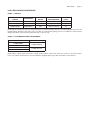
Chart 1 – Air Caps
PART NO. FOR
AIR CAP
TECHNOLOGY
MARKING ON
AIR CAP
RECOMMENDED
INLET PRESSURE
AIR FLOW
(L/min)
COMM-100-HS1
HVLP
HS1
29.0 psi (2.0 bar)
135
COMM-100-TS1
TRANS-TECH®
TS1
29.0 psi (2.0 bar)
100
COMM-100-RS1
TRANS-TECH®
RS1
14.0 psi (1.0 bar)
55
NOTE: When removing air cap from retaining ring, don’t remove the Slip Ring (2) or Retaining Ring Seal (5) from the
Retaining Ring. Damage to the parts may occur. Slip ring and Retaining Ring seal are not available as replacements.
Simply wipe parts clean and reassemble with new or clean air cap.
Chart 2 – Fluid Nozzle Range & Fluid Needle
PART NO. ON FLUID NOZZLE
COMM-200-08
COMM-200-10
COMM-200-12
COMM-200-14
PART NO. NEEDLE
COMM-300-0810
COMM-300-1214
NOTE: When replacing the fluid nozzle or fluid needle, replace both at the same time. Torque to 70 in-lbs (8 Nm).
Don’t over tighten the fluid nozzle. Use 6mm Spanner supplied with the gun and check with a torque wrench.
Page 14
SB-2-858-B
Troubleshooting Possible Problems in Operation
CONDITION
CAUSE
CORRECTION
Heavy top or
bottom pattern
Horn holes plugged.
Clean. Ream with non-metallic point.
Obstruction on top or bottom of fluid
nozzle.
Clean.
Cap and/or nozzle seat dirty.
Clean.
Left or right side horn holes plugged.
Clean. Ream with non-metallic point.
Dirt on left or right side of fluid
nozzle.
Clean.
Heavy right or
left side pattern
Remedies for the top-heavy, bottom-heavy, right-heavy, and left-heavy patterns:
1. Determine if the obstruction is on the air cap or the fluid nozzle. Do this by making a test spray pattern. Then,
rotate the cap one-half turn and spray another pattern. If the defect is inverted, obstruction is on the air cap. Clean
the air cap as previously instructed. Also check for dried paint just inside the cap center hole opening; remove by
washing with solvent.
2. If the defect is not inverted, it is on the fluid nozzle. Clean nozzle. If problem persists, renew nozzle.
Heavy center
pattern.
Split spray
pattern
Jerky or
fluttering spray
Paint bubbles in cup
Spreader adjustment valve set too
low.
Turn out counter clockwise to
achieve correct pattern.
Atomizing pressure too low.
Increase pressure.
Material too thick.
Thin to correct consistency.
Air pressure too high.
Reduce at regulator or gun handle.
Fluid adjusting knob turned in too far.
Turn out counter clockwise to
achieve correct pattern.
Spreader adjusting valve set too
high.
Turn in clockwise to achieve correct
pattern.
Loose or damaged fluid nozzle/seat
Tighten or replace
Loose or broken cup fluid nipple
Tighten or replace cup
Material level too low
Refill
Container tipped too far
Hold more upright
Obstruction in fluid passage
Back flush with solvent
Loose fluid needle packing nut
Tighten
Damaged fluid needle packing
Replace
Fluid nozzle not tight.
Fluid nozzle not tight. Tighten to
70 in-lbs (8 Nm).
SB-2-858-B
Page 15
Troubleshooting Possible Problems in Operation
Fluid leaking or dripping from
cup lid
Starved spray pattern
Cup lid loose.
Push in or replace.
Dirty cup or lid.
Clean.
Cracked cup or lid.
Replace cup and lid.
Inadequate material flow
Wind fluid adjusting knob out or
change to larger fluid nozzle size.
Blocked vent in Cup lid
Clean lid and unblock vent.
Low atomization air pressure
Increase air pressure and rebalance
gun.
Air pressure to high.
Reduce air pressure.
Gun too far from work surface.
Adjust to correct distance.
Air pressure too high.
Reduce air pressure.
Gun too far from work surface.
Adjust to correct distance.
Gun motion too fast.
Slow down.
Fluid flow too low.
Wind out needle adjusting screw or
use larger nozzle size.
Packing worn.
Replace.
Fluid nozzle or fluid needle worn or
damaged.
Replace fluid nozzle and fluid needle.
Foreign matter in fluid nozzle.
Clean.
Fluid needle dirty or stuck in needle
packing
Clean.
Wrong size fluid needle or fluid
nozzle.
Replace fluid nozzle and fluid needle.
Cup loose on gun.
Tighten.
Cup fluid inlet seat dirty.
Clean.
Too much material flow.
Turn fluid adjusting knob clockwise
or switch to smaller fluid nozzle and
fluid needle size.
Material too thin.
Mix correctly or apply light coats.
Gun tilted on an angle, or gun
motion too slow.
Hold gun at right angle to work and
adapt to correct gun technique.
Excessive overspray
Dry spray
Fluid leaking from packing nut
Fluid leaking or dripping from
front of gun
Fluid dripping or leaking from
bottom of cup
Runs and sags
Page 16
SB-2-858-B
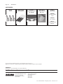
ACCESSORIES
72-2332
Swivel
42884-214-K5
Cleaning Brush
71-31101
ErgoFlex Hose with
1/4" Fittings
SRI-478-K12
Disposable Cup
Kit of 12
DeKups
Disposables
DPC-602
9 oz Disposable
Cups
DPC-607
9 oz. Frames
DPC-23
Disposable Cup
Adapter
U.S. Patent numbers 6,820,824 and 7,374,111 owned by 3M Innovation Properties Co.
Additional U.S. Patents: Nos. 7,380,680; 7,354,074; 7,353,964; 7,350,418; 7,344,040; 7,263,893; 7,165,732; 7,086,549.
WARRANTY
This product is covered by DeVilbiss’ 1 Year Limited Warranty.
DeVilbiss Sales and Service: www.devilbiss.com
U.S.A./Canada Customer Service
195 Internationale Blvd.
Glendale Heights, IL 60139
630-237-5000
Toll Free Customer Service
and Technical Support
800-992-4657
Toll Free Fax
888-246-5732
2/13 ©2013 DeVilbiss All rights reserved. Printed in U.S.A.