1
The heat pump and collector hose in general
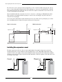
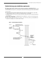
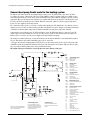
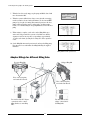
The collector hose can be connected to the heat pump with one or more circuits. In a multi-circuit system, the collector
pipes are connected in parallel as illustrated below. The parallel pipes are connected to two manifolds. Each coil should
have a shut off valve and a flow control valve. The flow control valve is adjusted so that the flow rate is the same in each
coil. The coils should have the same length.
After the manifolds and the flow control valves, the coils are connected to a collecting pipe. A filling link, filter and the
plastic expansion vessel supplied with the heat pump are connected to the collecting pipe. A pressure relief valve is
connected to the outgoing pipe.
One circuit at a time is filled with heat transfer fluid. Keep the valves closed in the other loops during the process. Read
more about filling under the heading Connecting the heat pump to the heating system.
Single circuit system
Multi-circuit system
Control valves
Expansion vessel
Collector
Expansion vessel
Filling link
Collector
Filling link
Manifolds
Heat pump
Heat pump
Installing the expansion vessel
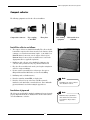
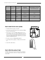
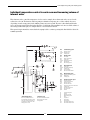
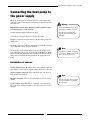
The plastic expansion vessel for the collector circuit is supplied with the heat pump. It is important to position it at
the highest point in the circuit, preferably above the heat pump. If there is a low ceiling making it impossible to fit the
expansion vessel above the pump, it can be positioned as illustrated in the diagram to the left. It is important to install the
expansion vessel so that any air disperses upwards. Air will remain in the circuit if the expansion vessel is fitted incorrectly
(see the figure to the right).
Correct
Wrong
12