1
M1622USB
16-CH 4-BUS MIXER
WITH FX AND USB
USER MANUAL
MANUALE D'USO
FCC COMPLIANCE NOTICE
This device complies with part 15 of the FCC rules. Opera on is subject to the following two condi ons:
(1) This device may not cause harmful interference, and
(2) this device must accept any interference received, including interference that may cause undesired opera on.
CAUTION: Changes or modifica ons not expressly approved by the party responsible for compliance could void
the user’s authority to operate the equipment.
NOTE: This equipment has been tested and found to comply with the limits for a Class B digital device, pursuant to
part 15 of the FCC Rules. These limits are designed to provide reasonable protec on against harmful interference in
a residen al installa on. This equipment generates, uses, and can radiate radio frequency energy and, if not installed
and used in accordance with the instruc on manual, may cause harmful interference to radio communica ons.
However, there is no guarantee that interference will not occur in a par cular installa on. If this equipment does
cause harmful interference to radio or television recep on, which can be determined by turning the equipment off
and on, the user is encouraged to try to correct the interference by one or more of the following measures:
• Reorient or relocate the receiving antenna.
• Increase the separa on between the equipment and receiver.
• Connect the equipment into an outlet on a circuit different from that to which the receiver is connected.
• Consult the dealer or an experienced radio/TV technician for help.
This marking shown on the product or its literature, indicates that it should not be disposed with other household wastes at the end of
its working life. To prevent possible harm to the environment or human health from uncontrolled waste disposal, please separate this
from other types of wastes and recycle it responsibly to promote the sustainable reuse of material resources. Household users should
contact either the retailer where they purchased this product, or their local government office, for details of where and how they can
take this item for environmentally safe recycling. Business users should contact their supplier and check the terms and condi ons of the
purchase contract. This product should not be mixed with other commercial wastes for disposal.
The lightning flash with arrowhead symbol within an equilateral triangle is intended to alert the user to the presence of uninsulated
“dangerous voltage” within the product’s enclosure, that may be of sufficient magnitude to cons tute a risk of electric shock to persons.
The exclama on point within an equilateral triangle is intended to alert the user to the presence of important opera ng and maintenance
(servicing) instruc ons in the literature accompanying the appliance.
The informa on contained in this publica on has been carefully prepared and checked. However no responsibility will be taken for any errors. All
rights are reserved and this document cannot be copied, photocopied or reproduced in part or completely without wri en consent being obtained
in advance from PROEL. PROEL reserves the right to make any aesthe c, func onal or design modifica on to any of its products without any prior
no ce. PROEL assumes no responsibility for the use or applica on of the products or circuits described herein.
Il marchio riportato sul prodo o o sulla documentazione indica che il prodo o non deve essere smal to con altri rifiu domes ci al
termine del ciclo di vita. Per evitare eventuali danni all’ambiente si invita l’utente a separare questo prodo o da altri pi di rifiu e di
riciclarlo in maniera responsabile per favorire il riu lizzo sostenibile delle risorse materiali. Gli uten domes ci sono invita a conta are
il rivenditore presso il quale è stato acquistato il prodo o o l’ufficio locale preposto per tu e le informazioni rela ve alla raccolta
differenziata e al riciclaggio per questo po di prodo o. Gli uten aziendali sono invita a conta are il proprio fornitore e verificare i
termini e le condizioni del contra o di acquisto. Questo prodo o non deve essere smal to unitamente ad altri rifiu commerciali.
Il simbolo del lampo con freccia in un triangolo equilatero intende avver re l'u lizzatore per la presenza di "tensioni pericolose" non isolate
all'interno dell'involucro del prodo o, che possono avere una intensità sufficiente a cos tuire rischio di scossa ele rica alle persone.
Il punto esclama vo in un triangolo equilatero intende avver re l'u lizzatore per la presenza di importan istruzioni per l'u lizzo e la
manutenzione nella documentazione che accompagna il prodo o.
Le informazioni contenute in questo documento sono state a entamente reda e e controllate. Tu avia non è assunta alcuna responsabilità per
eventuali inesa ezze. Tu i diri sono riserva e questo documento non può essere copiato, fotocopiato, riprodo o per intero o in parte senza
previo consenso scri o della PROEL. PROEL si riserva il diri o di apportare senza preavviso cambiamen e modifiche este che, funzionali o di
design a ciascun proprio prodo o. PROEL non assume alcuna responsabilità sull’uso o sul l’applicazione dei prodo o dei circui qui descri .
INDEX
INDICE
FCC COMPLIANCE NOTICE . . . . . . . . . . . . . . . . . . . 2
TECHNICAL SPECIFICATIONS . . . . . . . . . . . . . . . . . 4
MECHANICAL DIMENSIONS . . . . . . . . . . . . . . . . . . 5
LAYOUT . . . . . . . . . . . . . . . . . . . . . . . . . . . . . . . . . . 6
CONTROL PANEL (FIG.1) . . . . . . . . . . . . . . . . . . . . . 7
CONTROL PANEL (FIG.2) . . . . . . . . . . . . . . . . . . . . . 8
CONNECTIONS . . . . . . . . . . . . . . . . . . . . . . . . . . . . 8
CONFIGURATION EXAMPLE . . . . . . . . . . . . . . . . . . 9
ENGLISH LANGUAGE. . . . . . . . . . . . . . . . . . . . . . . 10
SAFETY AND PRECAUTIONS . . . . . . . . . . . . . . . . . 10
IN CASE OF FAULT . . . . . . . . . . . . . . . . . . . . . . . . . 10
CE CONFORMITY . . . . . . . . . . . . . . . . . . . . . . . . . . 10
PACKAGING, SHIPPING AND COMPLAINT . . . . . . 10
WARRANTY AND PRODUCTS RETURN . . . . . . . . . 10
INSTALLATION AND DISCLAIMER . . . . . . . . . . . . . 10
POWER SUPPLY AND MAINTENANCE . . . . . . . . . 10
GENERAL INFORMATION . . . . . . . . . . . . . . . . . . . 11
OPERATING INSTRUCTIONS (FIG. 1 / 2) . . . . . . . . 11
SPECIFICHE TECNICHE . . . . . . . . . . . . . . . . . . . . . . 4
DIMENSIONI MECCANICHE . . . . . . . . . . . . . . . . . . 5
LAY-OUT . . . . . . . . . . . . . . . . . . . . . . . . . . . . . . . . . 6
PANNELLO DI CONTROLLO (FIG.1) . . . . . . . . . . . . . 7
PANNELLO DI CONTROLLO (FIG.2) . . . . . . . . . . . . . 8
CONNESSIONI . . . . . . . . . . . . . . . . . . . . . . . . . . . . . 8
ESEMPIO CONFIGURAZIONE . . . . . . . . . . . . . . . . . 9
LINGUA ITALIANA . . . . . . . . . . . . . . . . . . . . . . . . . 19
AVVERTENZE PER LA SICUREZZA . . . . . . . . . . . . . 19
IN CASO DI GUASTO . . . . . . . . . . . . . . . . . . . . . . . 19
CONFORMITÀ CE . . . . . . . . . . . . . . . . . . . . . . . . . . 19
IMBALLAGGIO, TRASPORTO E RECLAMI . . . . . . . 19
GARANZIE E RESI . . . . . . . . . . . . . . . . . . . . . . . . . 19
INSTALLAZIONE E LIMITAZIONI D’USO . . . . . . . . . 19
ALIMENTAZIONE E MANUTENZIONE . . . . . . . . . . 19
INFORMAZIONI GENERALI . . . . . . . . . . . . . . . . . . 20
ISTRUZIONI OPERATIVE (FIG. 1 / 2) . . . . . . . . . . . 20
3
TECHNICAL SPECIFICATIONS
MODEL
SPECIFICHE TECNICHE
M1622USB
Connectors
MODELLO
M1622USB
MONO INPUT CHANNELS
Mic Input Sensi vity
from 0 to -60 dBu
Mic Input Impedance
2 Kohm
Line Input Sensi vity
from +20 to -40 dBu
Line Input Impedance
10 Kohm
Balanced XLR-F
Balanced Jack
Sensibilità Ingresso Mic
da 0 a -60 dBu
Impedenza Ingresso Mic
2 Kohm
Sensibilità Ingresso Line
da +20 a -40 dBu
Impedenza Ingresso Line
10 Kohm
LO CUT
75Hz, 18dB/oct.
FILTRO LO-CUT
75Hz, 18dB/oct.
EQ HIGH (shelving)
±15 dB @ 12KHz
EQ ALTI (shelving)
±15 dB @ 12KHz
EQ MID (peaking)
±15 dB @ 2.5KHz
EQ MEDI (peaking)
±15 dB @ 2.5KHz
EQ LOW (shelving)
±15 dB @ 80Hz
EQ BASSI (shelving)
±15 dB @ 80Hz
from 100 Hz to 8 KHz
STEREO INPUT CHANNELS
Mic Input Sensi vity
from 0 to -40 dBu
Mic Input Impedance
2 Kohm
Line Input Sensi vity
from +20 to -20 dBu
Line Input Impedance
10 Kohm
EQ HIGH (shelving)
Balanced XLR-F
Balanced Jack
Sensibilità Ingresso Mic
da 0 a -40 dBu
Impedenza Ingresso Mic
2 Kohm
Sensibilità Ingresso Line
da +20 a -20 dBu
Impedenza Ingresso Line
10 Kohm
EQ ALTI (shelving)
Jack Bilanciato
da 100 Hz a 8 KHz
EQ HI-MID (peaking)
±15 dB @ 3 KHz
EQ MEDIO-ALTI (peaking)
±15 dB @ 3 KHz
EQ LO-MID (peaking)
±15 dB @ 500 Hz
EQ MEDIO-BASSI (peaking)
±15 dB @ 500 Hz
±15 dB @ 80Hz
XLR-F Bilanciato
Jack Bilanciato
±15 dB @ 12KHz
EQ BASSI (shelving)
±15 dB @ 80Hz
MASTER SECTION
SEZIONE MASTER
MAIN MIX nom. out level
+4 dBu
Balanced Jack / XLR-M
MAIN MIX INSERT
0 dBu
TRS Jack
Livello nom. MAIN MIX
+4 dBu
Jack Bilanciato / XLR-M
INSERT MAIN MIX
0 dBu
TRS Jack
MIX/AUX Assignable EQ
graphic 7 band
GROUP nom. out level
+4 dBu
Balanced Jack
Livello nom. GROUP
+4 dBu
Jack Bilanciato
C.ROOM nom. out level
0 dBu
Unbalanced Jack
Livello nom. C.ROOM
0 dBu
Jack Sbilanciato
AUX nom. out level
0 dBu
Unbalanced Jack
Livello nom. AUX
0 dBu
Jack Sbilanciato
MIX/AUX EQ Assegnabile
graphic 7 band
2 - TRK nom. out level
0 dBu
Unbalanced Rca
Livello nom. 2 - TRK OUT
0 dBu
Rca Sbilanciato
2 - TRK nom. in level
0 dBu
Unbalanced Rca
Livello nom. 2 - TRK IN
0 dBu
Rca Sbilanciato
PHONES min. impedance
PHONES max. out level
USB
32 ohm
Stereo Jack
(2x) 193 mW
IN/OUT, 16bit / 48KHz
Type B
Impedenza min. PHONES
Livello max. PHONES
USB
DIGITAL EFFECT PROCESSOR - PROFEX
Presets
256 (16 presets x 16 varia ons)
32 ohm
Jack Stereo
(2x) 193 mW
IN/OUT, 16bit / 48KHz
256 (16 preset x 16 variazioni)
24 bit
A/D and D/A converters
24 bit
DSP resolu on
24 bit
DSP resolu on
24 bit
2-digit display, PRESET dial, PEAK LED, TAP DELAY
and MUTE with switch, footswitch and LED
Tipo B
DIGITAL EFFECT PROCESSOR - PROFEX
Presets
A/D and D/A converters
Controls
Controlli
GENERAL SPECIFICATIONS
2 display LED, sele ore PRESET, PEAK LED, TAP
DELAY e MUTE con tasto, pedale e LED
SPECIFICHE GENERALI
Max level all outputs
+22 dBu
Livello Massimo Uscite
+22 dBu
Crosstalk meas. at 1 KHz
> 82 dBu
Diafonia mis. a 1 KHz
> 82 dBu
HUM & N unweighted
< -93 dBu
HUM & N non pesato
< -93 dBu
THD+N at +4dB, 1kHz
< 0,008 %
THD+N a +4dB, 1kHz
< 0,008 %
465 x 91 x 462 mm
Dimensioni (L x A x P)
465 x 91 x 462 mm
Dimensions (W x H x D)
Weight
6.50 kg
Peso
POWER REQUIREMENTS
Mains Supply Voltage:
Consump on
4
XLR-F Bilanciato
CANALI INGRESSO STEREO
±15 dB @ 12 KHz
EQ LOW (shelving)
Conne ori
CANALI INGRESSO MONO
110-240 VAC (±10%) 50 / 60 Hz
available with Europe mains cord (Shucko plug),
US mains cord (NEMA 5-15P plug),
UK mains cord (BS1363 plug)
75 W
6,50 kg
ALIMENTAZIONE
Tensione di Rete:
Assorbimento
110-240 VAC (±10%) 50 / 60 Hz
disponibile con cavo rete Europa (spina Shucko),
cavo rete Sta Uni (spina NEMA 5-15P),
cavo rete Regno Unito (spina BS1363)
75 W
MECHANICAL DIMENSIONS
46.2 cm
18.2"
DIMENSIONI MECCANICHE
(9U RACK)
39.7 cm
15.6"
9.1 cm
3.60"
46.5 cm
18.3"
43.7 cm
17.2"
5
LAYOUT
6
LAY-OUT
CONTROL PANEL (FIG.1)
1
PANNELLO DI CONTROLLO (FIG.1)
59
81
23
71
2
24
3
25
4
26
68
70
69
65
5
61 62
63
64
46
48
60 66 57
58
59
79
6
80
50
7
7
8
27
9
28
30
47
49
51
43
10
10
11
11
31
12
12
32
13
13
14
14
15
15
16
29
17
17
18
18
19
19
20
20
21
21
22
22
33
52
44
83
82
53
45
73
78
37
77
34
76
72
75
36
54
55
74
56
38
40
41
42
7
CONTROL PANEL (FIG.2)
PANNELLO DI CONTROLLO (FIG.2)
87
86
85
CONNECTIONS
84
67
35
39
CONNESSIONI
Ɵp - hot
Ɵp - hot
ring - cold
cold
ground
sleeve - ground
LINE IN, various OUT
LINE IN, OUT vari
LINE IN, various OUT
LINE IN, OUT vari
Jack (balanced)
Jack (bilanciato)
Jack (unbalanced)
Jack (sbilanciato)
*note: connect both cold and ground
*nota: conneƩere insieme cold e ground
to make cable from balanced to unbalanced per cavi da bilanciato a sbilanciato
SEND
Ɵp - send
Ɵp - send
sleeve - ground
ring - return
Ɵp - return
sleeve - ground
RETURN
INSERT
INSERT
Jack stereo
Stereo Jack
(2x) Jack mono
(2x) Mono Jack
Ɵp - leŌ
hot
ring - right
cold
ground
sleeve - ground
PHONES
PHONES
2TRK IN, OUT
2TRK IN, OUT
Stereo Jack
Jack stereo
Jack (unbalanced)
Jack (sbilanciato)
*note: connect both cold and ground to
*nota: conneƩere insieme cold e ground
make cable from balanced to unbalanced per cavi da bilanciato a sbilanciato
8
ground
hot
cold
cold
hot
ground
MAIN MIX OUT
MAIN MIX OUT
MIC INPUT
MIC INPUT
Balanced female XLR
XLR bilanciato femmina
Balanced male XLR
XLR bilanciato maschio
CONFIGURATION EXAMPLE
ESEMPIO CONFIGURAZIONE
SAX MIC
ELECTRIC BASS
DRUM KIT
KEYBOARD
ELECTRIC GUITAR
DUAL 31 BAND EQUALIZER
VOCAL MIC
CHOIR MICS
ACOUSTIC
GUITAR
CD / MP3 / DVD RECORDER
AND PLAYER WITH AUDIO IN/OUT
DIBOX
FLASH12HDA
acƟve processed speaker
or other AUDIO SYSTEM
PERSONAL COMPUTER
WITH USB 2.0 PORT
HEADPHONES
normally
open
temporary
pedals
(proel: GF29)
external sound processor
WD12A wedge monitor
or other stage monitors
FLASH5A desktop monitors
or other AUDIO SYSTEM
9
ENGLISH LANGUAGE
SAFETY AND PRECAUTIONS
•
CAUTION: before using this product read carefully the following safety instruc ons. Take a look of this manual en rely and preserve it for
future reference.
When using any electric product, basic precau ons should always be taken, including the following:
– To reduce the risk, close supervision is necessary when the product is used near children.
– Protect the apparatus from atmospheric agents and keep it away from water, rain and high humidity places.
– This product should be site away from heat sources such as radiators, lamps and any other device that generate heat.
– Care should be taken so that objects and liquids do not go inside the product.
– The product should be connected to a power supply mains line only of the type described on the opera ng instruc ons or as marked on the
product. Connect the apparatus to a power supply using only power cord included making always sure it is in good condi ons.
–
WARNING: The mains plug is used as disconnect device, the disconnect device shall remain readily operable.
– Power supply cord should be unplugged from the outlet during strong thunderstorm or when le unused for a long period of me.
– Do not place objects on the product’s power cord or place it in a posi on where anyone could trip over, walk on or roll anything over it. Do not
allow the product to rest on or to be installed over power cords of any type. Improper installa ons of this type create the possibility of fire hazard
and/or personal injury.
IN CASE OF FAULT
•
–
–
–
–
–
•
In case of fault or maintenance this product should be inspected only by qualified service personnel when:
There is a flaw either in the connec ons or in the supplied connec ng cables.
Liquids have spilled inside the product.
The product has fallen and been damaged.
The product does not appear to operate normally or exhibits a marked change in performance.
The product has been lost liquids or gases or the enclosure is damaged.
Do not operate on the product, it has no user-serviceable parts inside, refer servicing to an authorized maintenance centre.
CE CONFORMITY
• Proel products comply with direc ve 2004/108/EC (EMC), as stated in EN 55013 standard and with direc ve 2006/95/CE (LVD), as stated in EN
60065 standard.
• Under the EM disturbance, the ra o of signal-noise will be changed above 10dB.
PACKAGING, SHIPPING AND COMPLAINT
• This unit package has been submi ed to ISTA 1A integrity tests. We suggest you control the unit condi ons immediately a er unpacking it.
• If any damage is found, immediately advise the dealer. Keep all unit packaging parts to allow inspec on.
• Proel is not responsible for any damage that occurs during shipment.
• Products are sold “delivered ex warehouse” and shipment is at charge and risk of the buyer.
• Possible damages to unit should be immediately no fied to forwarder. Each complaint for package tampered with should be done within eight
days from product receipt.
WARRANTY AND PRODUCTS RETURN
• Proel products have opera ng warranty and comply their specifica ons, as stated by manufacturer.
• Proel warrants all materials, workmanship and proper opera on of this product for a period of two years from the original date of purchase. If
any defects are found in the materials or workmanship or if the product fails to func on properly during the applicable warranty period, the owner
should inform about these defects the dealer or the distributor, providing receipt or invoice of date of purchase and defect detailed descrip on.
This warranty does not extend to damage resul ng from improper installa on, misuse, neglect or abuse. Proel S.p.A. will verify damage on returned
units, and when the unit has been properly used and warranty is s ll valid, then the unit will be replaced or repaired. Proel S.p.A. is not responsible
for any "direct damage" or "indirect damage" caused by product defec veness.
INSTALLATION AND DISCLAIMER
• Proel products have been expressly designed for audio applica on, with signals in audio range (20Hz to 20kHz). Proel has no liability for damages
caused in case of lack of maintenance, modifica ons, improper use or improper installa on non-applying safety instruc ons.
• Proel S.p.A. reserves the right to change these specifica ons at any me without no ce.
• Proel S.p.A. declines any liability for damages to objects or persons caused by lacks of maintenance, improper use, installa on not performed
with safety precau ons and at the state of the art.
POWER SUPPLY AND MAINTENANCE
• Clean only with dry cloth.
• Before connec ng the product to the mains outlet make certain that the mains line voltage matches that shown on the rear of the product, a
tolerance of up to ±10% is acceptable.
• CHECK THE CONDITION OF THE PROTECTION FUSE, ACCESSIBLE OUTWARD, ONLY WITH THE APPARATUS SWITCHED OFF AND
DISCONNECTED FROM THE MAINS LINE OUTLET.
• REPLACE THE PROTECTION FUSE ONLY WITH SAME TYPE AS SHOWN ON THE PRODUCT.
• IF AFTER THE SUBSTITUTION, THE FUSE INTERRUPTS AGAIN THE APPARATUS WORKING, DO NOT TRY AGAIN THEN CONTACT
THE PROEL SERVICE CENTER.
10
GENERAL INFORMATION
Thank you for having chosen a PROEL product.
The new models in the M Series have been updated with new and improved features, repacked into a new stylish
package. While keeping the superior audio quality, the full set of features and the highest number of MIC inputs in the
category that have been the hallmarks of the previous M Series, the M models feature the new PROEL 24bit PROFEX
DSP, one of the finest digital effect of its class, providing 256 studio-grade algorithms (including mono and stereo TAP
DELAY) and a convenient 2 digit LED display.
Designed and engineered in Italy by PROEL, M mixers are hosted in an ultra-rugged stylish metal case with ABS sides,
providing extended durability for a stage-proof use. As in the previous series, all the models include both a padded
carrying bag and metal brackets for 19” rack moun ng.
M1622USB, offering 16 inputs and 12 microphone channels, has been fi ed not only with one more AUX send and
with the USB rou ng, but also with an easy-to-use COMPRESSOR sec on on each MONO channel.
OPERATING INSTRUCTIONS (FIG. 1 / 2)
1. MIC Input
This is a female XLR connector, which accepts a balanced microphone input from almost any type of microphone. The
XLR inputs are wire as follows:
Pin 1 = shield or ground
Pin 2 = + posi ve or “hot”
Pin 3 = - nega ve or “cold”
2. LINE Input
This is a ¼” (6.3mm) jack connector, which accepts a balanced or unbalanced line level input signal from almost any
source. When connec ng a balanced signal, wire them as follows:
Tip = + posi ve or “hot”
Ring = - nega ve or “cold”
Sleeve = shield or ground
When connec ng an unbalanced signal, wire them as follows:
Tip = + posi ve or “hot”
Sleeve = shield or ground
3. INSERT Input-output
This is where you connect serial effects such as compressors, equalizers, de-essers or filters. The send is low-impedance
(150 ohms), capable of driving any line-level device. The return is high-impedance (10k ohms) and can be driven by
almost any device. Specialty “Y” cables, developed just for these jacks, are widely available on shops. Proel suggested
type is DHT540 (1.8 mt - 5.9 ). See also connec on chapter on this manual.
4. MONO CHANNEL GAIN Control
The gain control adjusts the input sensi vity of the mic and line inputs. This allows the signal from mics and instruments
to be adjusted to op mal internal levels. If the signals are plugged into the XLR input there is a 0 dB of gain with the
knob turned all way down, rising up to 60 dB of gain fully up. When connected to the jack input of any channels, there
is 20 dB of a enua on all way down and 40 dB of gain fully up, with a unity gain (0 dB) if centered.
5. LO CUT switch
This switch cuts bass frequencies below 75 Hz at a rate of 18 dB per octave. We recommend that you use the LO CUT
filter on every microphone applica on except kick drum, bass guitar, bassy synth patches, or recordings. These aside,
there isn’t much down there that you want to hear, and filtering it out makes the low stuff you do want much more
crisp and tasty. Not only that, but the LO CUT filter can help reduce the possibility of feedback in live situa ons and
it helps to conserve the amplifier power. Another way to use the LO CUT filter is in combina on with the LOW EQ on
vocals during live performances. Many mes, bass shelving EQ can really benefit voices. Trouble is, adding LOW EQ also
boosts stage rumble, mic handling clunks, and breath pops. LO CUT removes all those problems so you can add LOW
EQ without losing a woofer.
6. COMP compressor control and LED
Each mono channel features a single-control compressor, able to adjust the overall dynamic range of the signal and to
increase its loudness. When rota ng the control to the right, the loudest signals are reduced in order to avoid clipping,
while the quietest parts are boosted, producing a smooth, unified sound with no excessive peaks or distor on.
The adjacent LED lights when the effect is engaged.
NOTE: Avoid se ng the compression too high, as the higher average output level that results may lead to feedback.
11
7. EQ sec on HIGH control
This control gives you up to 15dB boost or cut at 12KHz with a “SHELVING” curve shape. Use it to increase or reduce
the sound “clarity” or “brightness”.
8. EQ sec on MID control
This control gives you up to 15 dB boost or cut at the frequency determined by the FREQ knob (see FREQ next) with a
"PEAKING" curve shape. Use it to add or reduce the sound "presence".
9. EQ sec on FREQ control
This knob ranges from 100 Hz to 8 kHz and determines the center frequency for the MID EQ. This allows you to zero in
on the precise narrow band of frequencies you want to have affected by the MID EQ.
10. EQ sec on LOW control
This control gives you up to 15dB boost or cut at 80Hz with a “SHELVING” curve shape. Use it to increase or reduce the
sound “punch”.
11. AUX 1 control (pre)
This control sends the channel signal to the AUX 1 output. This signal is always pre-fader, i.e. it is independent by the
posi on of the FADER LEVEL control.
12. AUX 2 control (pre)
This control sends the channel signal to the AUX 2 output. This signal is always pre-fader, i.e. it is independent by the
posi on of the FADER LEVEL control.
13. AUX 3 control (pre/post)
This control sends the signal to the AUX 3 output. This signal is normally pre-fader, but it could be set post-fader pressing
the POST switch: in this case the signal level depends on the posi on of the channel FADER.
14. POST switch
Push this switch to set the AUX 3 control post-fader or release it to set the AUX 3 pre-fader. The pre-fader se ng is
preferable if you want to use the AUX 3 send as stage monitor, in order to have your stage mix independent from MAIN
MIX.
15. AUX 4 FX control (send to FX post)
This control sends the signal to the AUX 4 output and to the internal DIGITAL EFFECT PROCESSOR. This signal is postfader, in other words it depends on the posi on of the channel FADER.
16. PAN control
It adjusts the amount of channel signal sent to the le versus the right outputs. Use it to posi on the sound origin in a
panoramic stereo scene.
17. MUTE switch
When you engage a channel’s mute switch, its signal disappears from these outputs: MAIN MIX, GROUPS 1-2, AUX 1,
AUX 2, AUX 3, AUX4/FX.
NOTE: the input channel signal is not completely muted by this switch, so you can listen to it thru headphones and
C.ROOM outputs ac ng on the SOLO bu on in PFL mode only (see SOLO MODE).
18. MIX switch
Engaging this switch you assign the channel signal to the MAIN MIX bus regulated by the MAIN MIX faders. Typically,
the MIX switch will be engaged on all channels except those assigned separately to GROUPS 1-2.
19. 1-2 switch
Engaging this switch you assign the channel signal to the GROUPS 1-2 bus regulated by the GROUPS 1-2 faders. You
can use the GROUPS 1-2 jacks as separate outputs or, engaging the switch GRP TO MIX, to create a submix for a set of
channels (all the drums channels, for instance): in this case you can control the assigned GROUPS 1-2 signals together
and independently from the rest of the mix.
20. PEAK detector and SOLO ac ve
This LED has two func ons:
If the PEAK LED lights permanently this means that you have ac vated the SOLO switch of this channel.
If the PEAK LED flashes this means that the input signal is near to the CLIPPING point.
IMPORTANT: if the LED PEAK flashes reduce the level of the input signal using the GAIN control.
21. SOLO switch
This switch allows you to hear signals through your headphones or control room outputs and to display the level on LED
meters. Use the SOLO in live sets to pre-listen channels before they are fed into the mix or just to check out a par cular
channel any me during a session. You can solo as many channels at a me as you like.
IMPORTANT: The solo signal is pre-fader if SOLO MODE is in PFL posi on, so what you check is the signal entering the
12
channel. The solo signal is post-fader if SOLO MODE is in AFL posi on, so what you check is the signal sent from the
channel fader to the MAIN MIX.
22. FADER LEVEL control
It adjusts the level of the channel signal and sends it to the MAIN MIX and/or to the GROUPS 1-2 buses.
23. MIC MONO Input
This is a female XLR connector, which accepts a balanced microphone input from almost any type of microphone. Wiring
is the same of previous paragraphs.
24. LINE L MONO Input
This is a ¼” (6.3mm) jack connector, which accepts a balanced or unbalanced line level input signal from almost any line
source. If the LINE R jack is not inserted, this channel operates like a MONO channel with this input as a single signal
source. Wiring is the same of previous paragraphs.
25. LINE R Input
This is a ¼” (6.3mm) jack connector, which accepts a balanced or unbalanced line level input signal from almost any line
source. This is used only in presence of LINE L jack input to use the channel as STEREO.
26. STEREO CHANNEL GAIN Control
The gain control adjusts the input sensi vity of the mic and line inputs. This allows the signal from mics and instruments
to be adjusted to op mal internal levels. If the signals are plugged into the XLR input there is a 0 dB of gain with the
knob turned all way down, rising up to 40 dB of gain fully up. When connected to the jack input of any channels, there
is 20 dB of a enua on all way down and 20 dB of gain fully up, with a unity gain (0 dB) if centered.
27. EQ sec on HI MID control
This control gives you up to 15 dB boost or cut at 3 KHz with a "PEAKING" curve shape. Use it to add or reduce the
sound "clarity".
28. EQ sec on LO MID control
This control gives you up to 15 dB boost or cut at 500 Hz with a "PEAKING" curve shape. Use it to add or reduce the
sound "presence".
29. BAL control
It adjusts the amount of channel signal sent to the le versus the right outputs if the channel is used as MONO, or it
fades the LEFT or RIGHT signal amount if the channel is used as STEREO.
30. PRESETS selector and display
The internal PROFEX digital effect processor is built around a powerful DSP and 24bit AD/DA converters. It includes 16
different presets of studio-grade effect algorithm, each one featuring 16 different varia ons of the internal parameters,
for a total of 256 effects available.
HOW TO USE THE PROFEX EFFECT:
- rotate the SELECTOR knob to choose the type of effect (preset) you want to use;
- to select a varia on of the preset, press and hold the knob un l the display flashes;
- rotate the knob and choose one of the 16 varia ons available;
- press and hold again the knob un l the display stops flashing to confirm the selec on and to return back to the
preset selec on;
- send the signal to the effect with the AUX control (10) of the channel you want to add the effect to;
- rotate the FX LEVEL (25) knob un l you hear the effect added to the original signal;
- adjust the AUX controls (10) just before the signal input clipping indicated by the peak led (22);
- re-adjust the FX LEVEL (25) knob to combine the wet effected signal with the natural dry signal.
NOTE: the preset and the varia on selected in the PROFEX effect are kept in the memory even if you turn off the
mixer.
PRESET DESCRIPTION:
p 1. BRIGHT HALL - This type of reverb simulates the ambience of a grand concert hall. Dense, smooth reverb with
long pre delay and a lot of high frequency reflec ons. Works well with vocals, electric and acous c guitars, strings.
The VARIATIONS vary the decay me and the hall size from bigger [1] to smallest [16].
p 2. DARK HALL - This type of reverb simulates the ambience of a grand concert hall. Dense, smooth reverb with long
pre delay and a few of high frequency reflec ons. Works well with vocals, guitars, woodwinds.
The VARIATIONS vary the decay me and the hall size from bigger [1] to smallest [16].
p 3. BRIGHT ROOM - This type of reverb reproduces the more in mate ambience of natural room acous cs. Feature
a lot of early reflec ons with a lot of high frequency. Works well with vocals, woodwinds, strings, drums.
The VARIATIONS vary the decay me and the room size from bigger [1] to smallest [16].
13
p 4. DARK ROOM - This type of reverb reproduces the more in mate ambience of natural room acous cs. Feature a
lot lot of early reflec ons with a few of high frequency. Works well with vocals, fingered guitars, drums.
The VARIATIONS vary the decay me and the room size from bigger [1] to smallest [16].
p 5. VOCAL 1 (STAGE REVERB) - Amazing reverb designed for vocals with a long tail.
The VARIATIONS vary the decay me from long tail [1] to short tail [16], alterna ng plate, spring or hall types of
reverb.
p 6. VOCAL 2 (CLUB REVERB) - Amazing reverb designed for vocals with a dense tail.
The VARIATIONS vary the decay me from long tail [1] to short tail [16], alterna ng tape, hall or spring types of
reverb.
p 7. PLATE - This is a simula on of metal plate reverb, as used on classic recordings from the ‘70s and ‘80s.
The VARIATIONS vary the decay me from long tail [1] to short tail [16].
p 8. STEREO DELAY - Echo effect with ping-pong of le and right channels.
The VARIATIONS vary from long delay mes [1] to short delay mes [16].
p 9. STEREO TAP DELAY - Like STEREO DELAY above with me set by the user TAP bu on (22) just below.
The VARIATIONS vary from 5% [1] to 90% [16] of feedback quan ty.
p 10. MONO TAP DELAY - Typical mono delay with me set by the user TAP bu on (22) just below.
The VARIATIONS vary from 0% [1] to 75% [16] of feedback quan ty.
p 11. CHORUS - Typical modula on effect, provides a so , ethereal sweeping effect. Perfect for enhancement of
electric and acous c guitar and bass. Also adds a drama c effect to vocals, par cularly group harmonies and choirs.
The VARIATIONS increase the modula on frequency from 0.5Hz [1] to 5Hz [16].
p 12. FLANGER - Typical modula on effect, creates a strong sweeping effect, par cularly effec ve on rock electric
guitar, lead and rhythm.
The VARIATIONS increases the modula on frequency from 0.2Hz [1] to 3Hz [16].
p 13. REVERB+DELAY 1 - Typical vocal hall reverb and stereo delay combined together.
The VARIATIONS vary from long tail [1] to short tail [16].
p 14. REVERB+DELAY 2 - Typical vocal hall reverb and mono delay combined together.
The VARIATIONS vary from long tail [1] to short tail [16].
p 15. REVERB+TAP DELAY - Typical vocal hall reverb and mono TAP delay combined together.
The mono delay me is set by the user TAP bu on (22) just below.
The VARIATIONS vary from long tail [1] to short tail [16] and from 0% to 75% of feedback quan ty [1-16].
p 16. REV+CHORUS - Typical vocal reverb and chorus effect combined together.
The VARIATIONS vary from long tail [1] to short tail [16] and increases the modula on frequency from 0.5Hz to 5Hz
[1-16].
31. FX TO AUX1 level control
It adjusts the level of the internal effect signal sent to the AUX 1 output.
32. FX TO AUX2 level control
It adjusts the level of the internal effect signal sent to the AUX 2 output.
33. FX TO AUX3 level control
It adjusts the level of the internal effect signal sent to the AUX 3 output.
34. TAP bu on and LED
When “TAP DELAY” effects (p 9, 10, 15) are selected, by pushing at least two mes this bu on it’s possible to set the
desired delay me, according to music rhythm. The TAP LED flashes in sync with the delay me set.
35. FX TAP jack input
¼” (6.3mm) unbalanced (TS) jack for temporary, normally open footswitch (not supplied - suggested footswitch is the
PROEL model GF29). When “TAP DELAY” effects (p 9, 10, 15) are selected, by pressing at least two mes the footswitch
it’s possible to set the desired delay me, according to music rhythm.
36. PEAK detector
If the peak LED flashes this means that the signal is too high, near to the clipping of the effect input stage. In this case,
reduce the level of the AUX4 / FX channel sends (15) or AUX SEND 4 FX master send (37).
37. AUX SEND 4 FX LEVEL control
It adjusts the master level of AUX4 jack output and also the signal sent to internal effect. Use it to reduce the level of
signal sent to the internal effect if the PEAK LED is flashing. This control ranges from off through unity (the center detent
posi on) on up to 15 dB of extra gain (fully clockwise).
38. MUTE bu on
Engage this switch if you want to mute the signal from the internal effect.
NOTE: the effect can be turned on/off also by means of a footswitch connected to the FX MUTE jack socket.
14
39. FX MUTE jack input
You can connect a footswitch to MUTE the mixer internal effect (suggested footswitch is PROEL model GF29).
40. MIX / 1-2 switch
This switch assigns the FX output signal to the MAIN MIX bus (if dis-engaged) or to the GROUP 1-2 bus (if engaged).
Typically, it is set to MIX if the internal effect is used only for channels assigned to MIX bus or to 1-2 if the internal effect
is used only for channels assigned to 1-2 bus.
41. FX SOLO switch and LED
This switch allows you to hear the signals of FX send (PFL) or FX return (AFL) through your headphones or control room
outputs and to display the level on LED meters.
42. FX LEVEL control
It adjusts the level of the internal effect signal sent to the MAIN MIX or GROUPS 1-2 outputs.
43. AUX 1 SEND LEVEL control
It adjusts the general level of the AUX 1 SEND output. This control ranges from off to +15 dB of gain when fully clockwise.
44. AUX 2 SEND LEVEL control
It adjusts the general level of the AUX 2 SEND output. This control ranges from off to +15 dB of gain when fully clockwise.
45. AUX 3 SEND LEVEL control
It adjusts the general level of the AUX 3 SEND output. This control ranges from off to +15 dB of gain when fully clockwise.
46. AUX SEND 1 jack output
This jack connector sends out unbalanced line-level signals made of the sum of the input channel’s AUX 1 sends, usually
for connec ng to the inputs of an external effect devices or stage monitor amplifiers.
47. AUX SEND 2 jack output
This jack connector sends out unbalanced line-level signals made of the sum of the input channel’s AUX 2 sends, usually
for connec ng to the inputs of an external effect devices or stage monitor amplifiers.
48. AUX SEND 3 jack output
This jack connector sends out unbalanced line-level signals made of the sum of the input channel’s AUX 3 sends, usually
for connec ng to the inputs of an external effect devices or stage monitor amplifiers. This signal can be pre or post fader,
it depends how POST switch (14) of each channel is set, usually all bu ons are set as pre or post.
49. AUX SEND 4 jack output
This jack connector sends out unbalanced line-level signals made of the sum of the input channel’s AUX 4 sends, usually
for connec ng to the inputs of an external effect devices. This signal is post-fader, or in other words it depends on the
posi on of the channel’s FADER.
50. AUX RETURN jack input
Unbalanced jack connectors of the auxiliary stereo input (note: the L input can be used as MONO if R input is le
unconnected). This input can be used for the return signal from outboard effects or for connec ng any instrument or
equipment with a line output.
51. AUX RETURN TO MIX level control
It adjusts the level of the AUX RETURN inputs and send it to the MAIN MIX.
52. AUX RETURN TO AUX 1 level control
It adjusts the level of the AUX RETURN inputs and send it to the AUX 1 output.
53. AUX RETURN TO AUX 2 level control
It adjusts the level of the AUX RETURN inputs and send it to the AUX 2 output.
54. GROUPS 1-2 FADER control
The GROUP 1-2 FADERS control the level of the GROUP 1-2 bus to its outputs or, if "GRP TO MIX" switch is down, to the
MAIN MIX bus.
55. GRP TO MIX switch
This switch assigns the GROUP 1-2 bus to the MAIN MIX bus. As explained earlier, pushing down this switch you can use
the GROUP 1-2 as sub-mix groups, enabling you to control the level of several channels with one knob.
56. MAIN MIX FADER level control
The MAIN MIX FADER controls the output level just before the MAIN MIX outputs. When the fader is fully down the
MAIN MIX is off , the “0” marking indicates a +4 dBu nominal output level. Typically this fader is set near the “0” label
and le alone, but it can be used for song fadeouts or quick system-wide mutes.
NOTE: the MAIN OUT is a true balanced output that can send the signal on a balanced line with or without a phantom
power ac ve. So the M1622USB mixer can also be used as a combina on mixer + DI box for sending the signals to a
15
bigger main mixer console.
57. GROUPS 1-2 jack output
These JACK connectors provide an unbalanced line-level signal from the GROUPS 1-2 stereo bus signal overall controlled
by the GROUPS 1-2 FADER level control.
58. MAIN MIX INSERT Input output
This is where you connect serial effects before the MAIN MIX FADER control. These serial effects usually are compressors
or equalizers. The send is low-impedance (150 ohms), capable of driving any line-level device. The return is highimpedance (10k ohms) and can be driven by almost any device. Specialty “Y” cables, designed just for this applica on,
are widely available on shops. Specialty “Y” cables, developed just for these jacks, are widely available on shops. Proel
suggested type is DHT540 (1.8 mt - 5.9 ). See also connec on chapter on this manual.
59. MAIN MIX L & R xlr and jack output (balanced)
These XLR and jack connectors provide a balanced line-level signal that represents the fully mixed stereo signal
controlled by the MAIN MIX fader. Connect these to the inputs of your power amplifier, powered speaker or processors
(equalizers, mul -band compressors and so on).
60. 2TRK inputs
Use these unbalanced RCA connectors to patch the output of a player, such as an analog tape deck, MP3 player, CD/DVD
player or a Personal Computer.
61. USB/2TRK IN level control
It adjusts the level of the 2TRK INPUT and USB input (audio signal from PC).
62. MIX - CH15/16 switch
This switch routes the 2TRK IN or USB input signal directly to MAIN MIX outputs or to the channel 15/16. Rou ng the
signal to channel 15/16, you can use all features of the stereo channel before sending the signal to the MAIN MIX:
equaliza on, aux sends and the internal effect processor.
63. 2 TRK OUT PEAK detector
If the peak LED flashes mean that the signal is too high, near to the clipping the output stage. In this case, reduce the
level of the USB/2TRK OUT level control.
64. MIX - AUX 1-2 switch
This switch selects which signal is sent to the 2TRK OUT and to the USB port. Choosing the MAIN MIX signal you can
record a whole mix session such as a live performance. Choosing AUX 1-2 you can record ll two different instruments
in two different tracks of your DAW recording so ware, rou ng them thru AUX 1 and AUX 2 respec vely and using the
MAIN MIX for monitoring.
65. USB/2TRK OUT level control
It adjust the level of signal sent to the 2TRK OUTPUT and to the USB port. This control is a er the MAIN MIX fader
control.
66. 2TRK outputs
Use these unbalanced RCA connectors to send out the MAIN MIX or AUX 1/2 signals to a recorder, such as an analog
tape or an A/D converter connected to a Personal Computer.
67. USB PORT socket
It routes the 2TRK OUT and the 2TRK IN through the USB port in crystal-clean, 16-bit, 44.1 kHz stereo digital audio. Use
the M1622USB as a high-quality soundcard for recording and playback with Windows and Macintosh computers.
VERY IMPORTANT INFORMATIONS:
- The M1622USB internal USB soundcard needs a personal computer with a USB 2.0 port and a Windows (XP or later)
or Mac OSX (10.3 or later) Opera ng Systems.
- The internal USB soundcard DOESN'T REQUIRE A DEDICATE SOFTWARE DRIVER to work with Windows or Mac OSX.
- For in/out signal rou ng inside the computer and the DAW so ware refer to the documenta on included with the
computer and DAW so ware.
- Tipically, a er you have connected the USB cable and powered on the mixer, the M1622USB soundcard is visible from
the computer and DAW so ware as: "USB Audio CODEC" (or with a similar name, depending on the OS version).
68. EQ IN / BYPASS switch
Engaging this switch you bypass the 7-band STEREO graphic equalizer, whether is used on MIX outputs or on AUX
sends.
69. MIX L / AUX 1 switch
This bu on assigns the LEFT channel of the 7-band STEREO graphic equalizer to MIX LEFT (switch released) or to AUX
1 send (bu on pressed). Use the equalizer on the MIX outputs to correct the response of your main speaker system or
16
use it on the AUX's sends to avoid feedbacks on stage monitors.
IMPORTANT: press always both MIX L / AUX1 and MIX R / AUX2 switches to assign both the equalizers channels at the
same me to MIX outputs LEFT & RIGHT or to AUX's sends 1 & 2.
70. MIX R / AUX 2 switch
This bu on assigns the RIGHT channel of the 7-band STEREO graphic equalizer to MIX RIGHT (switch released) or to
AUX2 send (bu on pressed). Use it ALWAYS together with MIX L / AUX 2 bu on.
71. STEREO GRAPHIC EQ slider
These sliders gives you up to 15 dB boost or cut at 63 Hz, 125 Hz, 400 Hz, 1 KHz, 2.5 KHz, 8 KHz and 16 KHz.
72. STAND-BY switch
Engage the STAND-BY switch and instantly the en re MAIN MIX is switched off . You can use this switch as a MASTER
MUTE while you are wai ng for the gig to start. Since the 2TRK IN input it's s ll assigned to the MAIN MIX when the
STAND-BY bu on is pressed, you can also play some music during the intermission. When it's me to start the gig, just
release the bu on and all musicians will be ready to play.
73. L & R LEVEL METERS
The level meters are made of two columns of of twelve LEDs with three colours to indicate different ranges of signal
level:
• green = shows the normal opera ve level of the signal (from -30 to +4 dBu)
• yellow = shows the nominal opera ve level of the signal (from +7 to +10 dBu)
• red = shows a high signal level (near +20 dBu CLIP level).
If the SOLO switch is dis-engaged, the meters display what is selected by (75) (76) and (77) switches, choosing between
MAIN MIX (post fader), GROUP 1-2 (post fader) or 2TRK IN.
If one or more SOLO switches are engaged, the meters display the solo informa on. If the SOLO MODE is set as PFL
(pre fader level) the meters show only a mono signal on both column, if it is set as AFL (a er fader level) they show the
stereo signal a er the channel FADER and PAN controls.
NOTE: in order to obtain a proper visualiza on, we recommend to press only one switch at a me.
74. SOLO MODE switch
Allows to select if the listening and the visualiza on of the channels selected with the SOLO bu ons are PRE FADER
(PFL) or POST FADER (AFL).
- PFL: PRE-FADER LEVEL, the input signal, already controlled by the channel EQ, is shown on the LED METERS and sent
to the C.ROOM/PHONES outputs. The PFL mode has to be used for se ng the right level of the input signal (usually
around 0 dB) and to avoid input satura on and distor on.
- AFL: AFTER-FADER LEVEL, the input signal, already controlled by the channel EQ and by the channel fader, is shown on
the LED METERS and sent to the C.ROOM/PHONES outputs.
75. 2TRK to C.ROOM switch
Push this switch to send the 2TRK input signal and USB input signal to C.ROOM and PHONES outputs.
76. MIX to C.ROOM switch
Push this switch to send the MIX bus signal to C.ROOM and PHONES outputs.
77. 1-2 to C.ROOM switch
Push this switch to send the GROUP 1-2 bus signal to C.ROOM and PHONES outputs.
NOTE: for a correct opera on we suggest to choose these three switches (75) or (76) or (77) one a me.
IMPORTANT: these switches also select which signal is displayed on LED METERS when none channel is soloed.
78. C.ROOM/PHONES LEVEL control
This controls the CONTROL ROOM and PHONES output’s level.
NOTE: The signal at these outputs is the same.
79. C.ROOM jack outputs
These JACK connectors provide an unbalanced line-level signal that can be used to monitor the MAIN MIX / GRP 1-2 /
USB 2TRK IN program or what is soloed.
80. PHONES stereo jack output
STEREO JACK connector for the headphones output: only stereo headphones with a minimum impedance of 32 Ohms
should be connected to this output.
81. LAMP 12V / 0.5A socket
This BNC connector provides +12V power supply for gooseneck lamps. Use only lamps with MAX 5W power consump on.
PROEL suggested types are SDC670 or SDC670LED.
17
82. +48V phantom switch and LED
This switch ac vates (LED on) and deac vates (LED off) the phantom power on MIC Inputs. Most professional condenser
microphones require phantom power, which is a lower DC voltage delivered to the microphone on pin 2 and 3 of the
XLR microphone connector. Dynamic microphones do not require phantom power, however phantom power will not
harm most dynamic microphones should you plug one in while the phantom power is on. Check the manual of your
microphone to find out for sure whether or not phantom power can damage it.
83. ON led
Indicates when the mixer is switched on.
84. POWER switch
Make sure that all master output knobs are turned all the way down when powering your mixer up or down.
85. AC~ socket
Here’s where you plug in your mixer’s mains supply cord. You should always use the mains cord supplied with the mixer.
Be sure your mixer is turned off before you plug the mains supply cord into an electrical outlet.
86. FUSE holder
Here is placed the mains protec on fuse. Please follow the instruc ons on page 10 of this manual to replace it.
87. PRODUCT LABEL
In this label are wri en the most important informa on about the mixer, model, line voltage, consump on, serial
number.
18
LINGUA ITALIANA
AVVERTENZE PER LA SICUREZZA
•
ATTENZIONE: Durante le fasi di uso o manutenzione, devono essere prese alcune precauzioni onde evitare danneggiamen alle stru ure
meccaniche ed ele roniche del prodo o.
Prima di u lizzare il prodo o, si prega di leggere a entamente le seguen istruzioni per la sicurezza. Prendere visione del manuale d’uso e
conservarlo per successive consultazioni:
– In presenza di bambini, controllare che il prodo o non rappresen un pericolo.
– Posizionare l’apparecchio al riparo dagli agen atmosferici e a distanza di sicurezza dall’acqua, dalla pioggia e dai luoghi ad alto grado di umidità.
– Collocare o posizionare il prodo o lontano da fon di calore quali radiatori, griglie di riscaldamento e ogni altro disposi vo che produca calore.
– Evitare che qualsiasi ogge o o sostanza liquida entri all’interno del prodo o.
– Il prodo o deve essere connesso esclusivamente alla rete ele rica delle cara eris che descri e nel manuale d’uso o scri e sul prodo o, usando
esclusivamente il cavo rete in dotazione e controllando sempre che sia in buono stato, in par colare la spina e il punto in cui il cavo esce dal prodo o.
–
ATTENZIONE: Se il cavo rete viene scollegato dall'apparecchio per spegnerlo, il cavo rete rimarrà opera vo in quanto la sua spina è ancora
collegata alla rete ele rica.
– Disconne ere il prodo o dalla rete ele rica durante for temporali o se non viene usato per un lungo periodo di tempo.
– Non disporre ogge sul cavo di alimentazione, non disporre i cavi di alimentazione e segnale in modo che qualcuno possa incianparci. Altresì
non disporre l’apparecchio sui cavi di altri appara . Installazioni inappropriate di questo po possono creare la possibilità di rischio di incendio
e/o danni alle persone.
IN CASO DI GUASTO
•
–
–
–
–
–
•
In caso di guasto o manutenzione questo prodo o deve essere ispezionato da personale qualificato quando:
Ci sono dife sulle connessioni o sui cavi di collegamento in dotazione.
Sostanze liquide sono penetrate all’interno del prodo o.
Il prodo o è caduto e si è danneggiato.
Il prodo o non funziona normalmente esibendo una marcato cambio di prestazioni.
Il prodo o perde sostanze liquide o gassose o ha l’involucro danneggiato.
Non intervenire sul prodo o. Rivolgersi a un centro di assistenza autorizzato Proel.
CONFORMITÀ CE
• I Prodo Proel sono conformi alla dire va 2004/108/EC (EMC), secondo lo standard EN 55013 ed alla dire va 2006/95/CE (LVD), secondo lo
standard EN 60065.
• Se so oposto a disturbi EM, il rapporto segnale-rumore può essere superiore a 10dB.
IMBALLAGGIO, TRASPORTO E RECLAMI
• L’imballo è stato so oposto a test di integrità secondo la procedura ISTA 1A. Si raccomanda di controllare il prodo o subito dopo l’apertura dell’imballo.
• Se vengono riscontra danni informare immediatamente il rivenditore. Conservare quindi l’imballo completo per perme erne l’ispezione.
• Proel declina ogni responsabilità per danni causa dal trasporto.
• Le merci sono vendute “franco nostra sede” e viaggiano sempre a rischio e pericolo del distributore.
• Eventuali avarie e danni dovranno essere contesta al ve ore. Ogni reclamo per imballi manomessi dovrà essere inoltrato entro 8 giorni dal ricevimento.
GARANZIE E RESI
• I Prodo Proel sono provvis della garanzia di funzionamento e di conformità alle proprie specifiche, come dichiarate dal costru ore.
• La garanzia di funzionamento è di 24 mesi dopo la data di acquisto. I dife rileva entro il periodo di garanzia sui prodo vendu , a ribuibili a materiali
dife osi o dife di costruzione, devono essere tempes vamente segnala al proprio rivenditore o distributore, allegando evidenza scri a della data
di acquisto e descrizione del po di dife o riscontrato. Sono esclusi dalla garanzia dife causa da uso improprio o manomissione. Proel SpA constata
tramite verifica sui resi la dife osità dichiarata, correlata all’appropriato u lizzo, e l’effe va validità della garanzia; provvede quindi alla sos tuzione o
riparazione dei prodo , declinando tu avia ogni obbligo di risarcimento per danni dire o indire eventualmente derivan dalla dife osità.
INSTALLAZIONE E LIMITAZIONI D’USO
• I Prodo Proel sono des na esclusivamente ad un u lizzo specifico di po sonoro: segnali di ingresso di po audio (20Hz-20kHz). Proel declina ogni
responsabilità per danni a terzi causa da mancata manutenzione, manomissioni, uso improprio o installazione non eseguita secondo le norme di sicurezza.
• La Proel S.p.a. si riserva di modificare il prodo o e le sue specifiche senza preavviso.
• Proel declina ogni responsabilità per danni a terzi causa da mancata manutenzione, manomissioni, uso improprio o installazione non eseguita
secondo le norme di sicurezza e a regola d'arte.
ALIMENTAZIONE E MANUTENZIONE
• Pulire il prodo o unicamente con un panno asciu o.
• Prima di collegare l'apparecchio alla presa di corrente, accertatevi che la tensione di rete corrisponda a quella indicata sul retro dell’apparato, è
consen to un margine del ±10% rispe o al valore nominale.
• CONTROLLARE LO STATO DEL FUSIBILE DI PROTEZIONE ACCESSIBILE DALL'ESTERNO ESCLUSIVAMENTE AD APPARATO SPENTO E
DISCONNESSO DALLA RETE ELETTRICA.
• RIMPIAZZARE IL FUSIBILE DI PROTEZIONE ESCLUSIVAMENTE CON UN FUSIBILE CON LE MEDESIME CARATTERISTICHE RIPORTATE
SUL PRODOTTO.
• SE DOPO LA SOSTITUZIONE, IL FUSIBILE INTERROMPE NUOVAMENTE IL FUNZIONAMENTO DELL'APPARATO, NON INSISTERE E
CONTATTARE IL SERVIZIO ASSISTENZA PROEL.
19
INFORMAZIONI GENERALI
Grazie per aver scelto un prodo o PROEL.
I nuovi modelli della serie M sono sta aggiorna con nuove e migliori cara eris che e con un design innova vo e
originale. Oltre a mantenere i pun di forza della precedente serie M, tra cui la qualità audio superiore, un set completo
di funzioni e il maggiore numero di ingressi MIC della categoria, tu i nuovi modelli serie M dispongono del nuovo DSP
PROEL a 24bit PROFEX, uno dei migliori effe digitali u lizza su mixer compa , che include 256 algoritmi di qualità
studio (inclusi TAP DELAY mono e stereo) ed un u le display LED a 2 digit.
Proge a ed ingegnerizza in Italia da PROEL, i mixer M sono alloggia in telai di metallo ultra-robus ed elegan
con fianchi in ABS, in grado di garan re un uso prolungato a prova di palco. Tu i modelli includono sia una borsa da
trasporto imbo ta che ada atori per il montaggio in rack da 19”.
Il nuovo mixer M1622USB, dispone di 16 ingressi di cui 12 microfonici come il modello precedente, include una mandata AUX in
più e una flessibile ges one del segnale USB del computer e dotato inoltre di un COMPRESSORE per ogni ingresso MONO.
ISTRUZIONI OPERATIVE (FIG. 1 / 2)
1. MIC (ingresso microfono)
È un conne ore femmina XLR, in grado di acce are un segnale microfonico bilanciato da ogni po di microfono.
L’ingresso XLR ha i seguen terminali:
Pin 1 = schermo o massa
Pin 2 = + posi vo o “caldo”
Pin 3 = - nega vo o “freddo”
2. LINE (ingresso linea)
È un conne ore femmina da ¼” (6.3mm) po jack, in grado di acce are un segnale a livello linea bilanciato o sbilanciato
da ogni po di sorgente. Quando si collega un segnale bilanciato, le terminazioni sono le seguen :
Tip (punta) = + posi vo o “caldo”
Ring (anello) = - nega vo o “freddo”
Sleeve (manico o) = schermo o massa
Quando si collega un segnale sbilanciato, le terminazioni sono le seguen :
Tip (punta) = + posi vo o “caldo”
Sleeve (manico o) = schermo o massa
3. INSERT (ingresso-uscita effe o)
A questo conne ore possono essere collega effe seriali quali compressori, equalizzatori, de-essers o filtri. La mandata
è a bassa impedenza (150 ohms), capace di pilotare ogni po di disposi vo con livello linea. Il ritorno è ad alta impedenza
(10k ohms) e può essere collegato ad ogni po di disposi vo con livello linea. Speciali cavi “Y”, realizza appositamente
per questa uscita jack, sono disponibili presso i negozi. Proel suggerisce il po DHT540 (1.8 mt - 5.9 ). Consultare anche
il capitolo delle connessioni in questo manuale.
4. GAIN (controllo guadagno)
Il controllo GAIN regola la sensibilità di ingresso dell’ingresso MIC o LINE. Questo perme e di regolare il segnale in
ingresso da microfoni o strumen al livello o male interno del mixer. Se il segnale è collegato all’ingresso XLR si hanno 0
dB di guadagno con la manopola girata al minimo e fino a 60 dB girandola verso il massimo. Quando collegato all’ingresso
jack si hanno 20 dB di a enuazione con la manopola girata al minimo e 40 dB di guadagno se girata al massimo, con un
guadagno unitario (0 dB) se posta al centro.
5. LO CUT (filtro elimina bassi)
Questo tasto elimina le basse frequenze al di so o dei 75 Hz con 18 dB per o ava. L’uso del filtro LO CUT è consigliato
su ogni microfono ecce o la grancassa, il basso, sinte zzatori o tracce pre-registrate. Infa , tranne che per ques
strumen , per tu gli altri al di so o di tale frequenza in genere non c’è nulla da ascoltare, eliminandoli i bassi restan
al di sopra dei 75Hz saranno più incisivi e piacevoli. Non solo ma dal vivo, in abbinamento al EQ LOW e in par colare
sulle voci, l’uso del filtro LO CUT riduce la possibilità di rientri (feedback) e preserva la potenza dell’amplificatore. LO CUT
elimina i rumori da maneggiamento dei microfoni, da vibrazioni del palco e dal respiro, rendendo possibile aumentare
i bassi con EQ LOW per dare maggior vigore alla voce.
6. COMP compressor control and LED
Ciascun canale mono include un compressore a controllo singolo, in grado di regolare il range dinamico del segnale e
di aumentarne l'intensità. Ruotando il controllo verso destra, i segnali di livello più elevato vengono limita per evitare
clipping, mentre le par di livello più basso vengono incrementate, producendo un suono omogeneo e uniforme, senza
picchi eccessivi o distorsioni.
Il LED adiacente si accende quando ,superata una certa soglia, si abilita la compressione.
NOTA: Evitare di usare compressioni troppo elevate, infa alzandosi il volume medio del segnale potrebbero
20
manifestarsi fenomeni di feedback.
7. EQ HI (equalizzatore controllo al )
Questo controllo perme e di guadagnare o a enuare fino a 15dB a 12KHz con una curva di po “SHELVING”. Da usarsi
per aumentare o ridurre la “chiarezza” o “brillanza” del suono.
8. EQ MID (eq. controllo intesità medi)
Questo controllo perme e di guadagnare o a enuare fino a 15 dB alla frequenza determinata dalla manopola FREQ
(vedi qui di seguito) con una curva po "PEAKING". Da usarsi per aumentare o ridurre la "presenza" del suono.
9. EQ FREQ (eq. controllo frequenza medi)
Questo controllo perme e di variare la frequenza del controllo MID da 100Hz a 8KHz, perme endo di focalizzare con
precisione la stre a banda di frequenze su cui il controllo MID EQ agisce.
10. EQ LOW (equalizzatore controllo bassi)
Questo controllo perme e di guadagnare o a enuare fino a 15dB a 80Hz con una curva di po “SHELVING”. Da usarsi
per aumentare o ridurre il “vigore” del suono.
11. AUX 1 (controllo livello ausiliario 1 pre)
Questo controllo invia il segnale all’uscita ausiliaria AUX 1. Questo segnale è pre-fader e può essere impostato
indipendentemente dalla posizione del controllo FADER LEVEL.
12. AUX 2 (controllo livello ausiliario 2 pre)
Questo controllo invia il segnale all’uscita ausiliaria AUX 2. Questo segnale è pre-fader e può essere impostato
indipendentemente dalla posizione del controllo FADER LEVEL.
13. AUX 3 (controllo livello ausiliario 3 pre/post)
Questo controllo invia il segnale all’uscita ausiliaria AUX 3. Questo segnale è normalmente pre-fader e può essere
impostato post-fader premendo il tasto POST: in questo caso dipenderà dalla posizione del controllo FADER LEVEL.
14. POST (tasto assegnazione post fader)
A tasto premuto si imposta il controllo AUX 3 come post-fader, a tasto sollevato si imposta AUX 3 come pre-fader.
Quest’ul ma impostazione è quella consigliata se si intende usare la mandata AUX 3 con un monitor di palco, per avere
il missaggio di palco indipendente dal MAIN MIX.
15. AUX 4 FX POST (controllo livello ausiliario 4 e/o effe o)
Questo controllo invia il segnale all’uscita ausiliaria AUX 4 e all’effe o interno (PROFEX digital effect processor). Questo
segnale è post-fader o in altre parole dipende dalla posizione del FADER di canale.
16. PAN (controllo panoramico)
Regola la quan tà del segnale da inviare alle uscite sinistra o destra. Da usarsi per posizionare il suono in una scena
panoramica stereo.
17. MUTE (tasto canale spento)
Quando si preme il tasto MUTE il segnale scompare dalle uscite MAIN MIX, GROUPS 1-2, AUX 1, AUX 2, AUX 3, AUX4 / FX.
NOTA: il segnale di ingresso del canale non è completamente silenziato da questo tasto e può essere ancora ascoltato
a raverso le uscite PHONES e C.ROOM azionando il tasto SOLO in modalità PFL (vedi SOLO MODE).
18. MIX (tasto assegnazione al MIX)
A vando questo interru ore si assegna il segnale del canale al bus MAIN MIX regolato dal fader MAIN MIX. Solitamente
l'interru ore MIX è a vato su tu i canali ecce o quelli assegna separatamente al bus GROUPS 1-2.
19. 1-2 (tasto assegnazione a GROUPS 1-2)
A vando questo interru ore si assegna il segnale del canale al bus GROUPS 1-2 regolato dai fader GROUPS 1-2. Si
possono usare i GROUPS 1-2 come uscite separate o, a vando il tasto GRP TO MIX, per creare un submix per un gruppo
di canali (per esempio tu i canali della ba eria): in questo caso i segnali assegna al GROUPS 1-2 saranno controlla
insieme e indipendentemente dal resto del mix.
20. PEAK (rilevatore di picco)
Il LED PEAK lampeggia quando il segnale di ingresso e prossimo alla distorsione.
IMPORTANTE: se il LED PEAK lampeggia, ridurre il livello del segnale di ingresso usando il controllo del guadagno
GAIN (4).
21. SOLO (tasto a vazione preascolto)
Questo tasto rende possibile il preascolto dei segnali dei canali alle cuffie e all’uscita C.ROOM e la visualizzazione del
livello sui LED meter. Usare il SOLO durante un’esibizione dal vivo per pre-ascoltare i segnali prima del missaggio o anche
per controllare se un canale è a posto durante il concerto. Premendo più tas SOLO si possono controllare anche più
canali simultaneamente.
IMPORTANTE: il segnale SOLO è pre-fader se SOLO MODE è in posizione PFL, quindi si tra a del segnale in ingresso nel
21
canale. Il segnale SOLO è post-fader se SOLO MODE è in posizione AFL, quindi si tra a del segnale inviato dal canale
al MAIN MIX.
22. FADER LEVEL (controllo di livello del canale)
Regola il livello del segnale del canale e lo invia ai bus MAIN MIX e/o GROUPS 1-2.
23. MIC LINE L/MONO (ingresso mic/linea)
È un conne ore femmina XLR, in grado di acce are con un conne ore XLR un segnale microfonico bilanciato da ogni
po di microfono. Quando viene usato questo ingresso, il canale opera come un canale microfonico mono. I terminali
sono gli stessi dei canali mono.
24. LINE L/MONO (ingresso linea sinistro)
È un conne ore da ¼” (6.3mm) po jack, in grado di acce are un segnale a livello linea bilanciato o sbilanciato da
ogni po di sorgente. Se il jack LINE R non è inserito, il canale opera come un canale MONO con questo ingresso come
sorgente unica.
25. LINE R (ingresso linea R)
È un conne ore da ¼” (6.3mm) po jack, in grado di acce are un segnale a livello linea bilanciato o sbilanciato da ogni
po di sorgente. È usato solo in presenza del jack LINE L per usare il canale in modalità STEREO.
26. GAIN (controllo guadagno)
Il controllo GAIN regola la sensibilità di ingresso dell’ingresso MIC o LINE. Questo perme e di regolare il segnale in
ingresso da microfoni o strumen al livello o male interno del mixer. Se il segnale è collegato all’ingresso XLR si hanno 0
dB di guadagno con la manopola girata al minimo e fino a 40 dB girandola verso il massimo. Quando collegato all’ingresso
jack si hanno 20 dB di a enuazione con la manopola girata al minimo e 20 dB di guadagno se girata al massimo, con un
guadagno unitario (0 dB) se posta al centro.
27. EQ HI MID (eq. controllo medio-al )
Questo controllo perme e di guadagnare o a enuare fino a 15 dB a 3 KHz con una curva po "PEAKING". Da usarsi per
aumentare o ridurre la "chiarezza" del suono.
28. EQ LO MID (eq. controllo medio-bassi)
Questo controllo perme e di guadagnare o a enuare fino a 15 dB a 500 Hz con una curva po "PEAKING". Da usarsi
per aumentare o ridurre la "presenza" del suono.
29. BAL (controllo bilanciamento)
Regola la quan tà del segnale da inviare alle uscite sinistra o destra se il canale è usato in MONO, oppure riduce la
quan tà di segnale destro e sinistro se il canale è usato in STEREO.
30. PRESETS (sele ore e display effe o)
L’effe o interno (PROFEX digital effect processor) è basato su un potente DSP e su conver tori AD/DA a 24bit. Include
16 preset con algoritmi di effe o studio-grade, ognuno dei quali dispone di 16 varian dei parametri, per un totale di
256 effe disponibili.
COME USARE l’EFFETTO PROFEX:
- ruotare il sele ore per scegliere il po di effe o (preset) che si vuole usare;
- per selezionare una variazione del preset, premere per almeno due secondi la manopola fino a quando il display lampeggia;
- quindi ruotare la manopola per scegliere una delle 16 variazioni;
- premere di nuovo per almeno due secondi la manopola finché il display sme e di lampeggiare per confermare la
variazione e tornare alla selezione dei preset;
- inviare il segnale all’effe o usando il controllo AUX (10) del canale a cui si vuole aggiungere l’effe o;
- ruotare la manopola FX LEVEL (25) fino ad udire l’effe o,
- regolare i controlli AUX (10) prima della saturazione del segnale indicata dal LED di picco (22),
- regolare nuovamente la manopola FX LEVEL (25) per combinare il segnale dell’effe o con il segnale naturale.
NOTA: il PROFEX man ene in memoria il preset e la variazione seleziona anche se il mixer viene spento.
DESCRIZIONE DEI PRESET:
p 1. BRIGHT HALL - Questo po di riverbero simula l’ambiente di una grande sala da concerto. Denso e armonioso
riverbero con una coda lunga e molte riflessioni di alte frequenze. Ada o a voci, chitarre ele riche e acus che, archi.
Le variazioni cambiano il tempo di decadimento e la grandezza della sala da grande [1] a piccola [16].
p 2. DARK HALL - Questo po di riverbero simula l’ambiente di una grande sala da concerto. Denso e armonioso
riverbero con una coda lunga e poche riflessioni di alte frequenze. Ada o a voci, chitarre, fia .
Le variazioni cambiano il tempo di decadimento e la grandezza della sala da grande [1] a piccola [16].
p 3. BRIGHT ROOM - Questo po di riverbero riproduce un più in mo ambiente acus co di una stanza. Cara erizzato
da veloci e sparpagliate prime riflessioni con molte alte frequenze. Ada o a voci, fia , archi, percussioni.
Le variazioni cambiano il tempo di decadimento e la grandezza della stanza da grande [1] a piccola [16].
22
p 4. DARK ROOM - Questo po di riverbero riproduce un più in mo ambiente acus co di una stanza. Cara erizzato
da veloci e sparpagliate prime riflessioni con poche alte frequenze. Ada o a voci, chitarre pizzicate, percussioni.
Le variazioni cambiano il tempo di decadimento e la grandezza della stanza da grande [1] a piccola [16].
p 5. VOCAL 1 (STAGE REVERB) - Riverbero modellato per voci con coda lunga.
Le variazioni cambiano il tempo di decadimento da lungo [1] a corto [16] alternando le varie pologie di riverberi
plate, spring o hall.
p 6. VOCAL 2 (CLUB REVERB) - Riverbero modellato per voci con coda densa.
Le variazioni cambiano il tempo di decadimento da lungo [1] a corto [16] alternando le varie pologie di riverberi
tape, hall o spring.
p 7. PLATE - Questa è una simulazione del classico riverbero “plate”, usato nelle registrazioni degli anni ‘70 e ‘80.
Le variazioni cambiano il tempo di decadimento da lungo [1] a corto [16].
p 8. STEREO DELAY - Effe o eco con ping-pong sui canali sinistro e destro.
Le variazioni vanno da un tempo di ripe zione lungo [1] a uno corto [16].
p 9. STEREO TAP DELAY - Come lo STEREO DELAY qui sopra con il tempo impostabile con il tasto TAP (22) posto so o.
Le variazioni cambiano la quan tà delle ripe zioni (feedback) dal 5% [1] al 90% [16].
p 10. MONO TAP DELAY - Tipico eco mono con tempo impostabile con il tasto TAP (22) posto so o.
Le variazioni cambiano la quan tà delle ripe zioni (feedback) dal 0% [1] al 75% [16].
p 11. CHORUS - Tipico effe o modulato provvisto di una soffice ed eterea ondulazione di frequenza. Perfe o per
esaltare chitarre e bassi ele rici ed acus ci. Esaltante anche su voci, in par colare gruppi o cori.
La variazione aumenta la frequenza di modulazione da 0.5 Hz [1] a 5 Hz [16].
p 12. FLANGER - Tipico effe o modulato cara erizzato da una decisa spazzolata in frequenza. Usato in par colare su
chitarre ele riche ed acus che, sia soliste che ritmiche.
La variazione aumenta la frequenza di modulazione da 0.2 Hz [1] a 3 Hz [16].
p 13. REVERB+DELAY 1 - Tipico riverbero per voce e stereo delay combina assieme.
Le variazioni cambiano il tempo di decadimento da lungo [1] a corto [16].
p 14. REVERB+DELAY 2 - Tipico riverbero per voce e mono delay combina assieme.
Le variazioni cambiano il tempo di decadimento da lungo [1] a corto [16].
p 15. REVERB+TAP DELAY - Tipico riverbero per voce po hall e mono TAP delay combina assieme.
Il tempo del mono delay è impostabile con il tasto TAP (22) posto so o.
Le variazioni cambiano il tempo di decadimento da lungo [1] a corto [16] e la quan tà delle ripe zioni (feedback) dal
0% al 75% [1-16].
p 16. REV+CHORUS - Tipico riverbero per voce e effe o chorus combina assieme.
Le variazioni cambiano il tempo di decadimento da lungo [1] a corto [16] ed aumentano la frequenza di modulazione
da 0.5Hz a 5Hz [1-16].
31. FX TO AUX1 (livello effe o su AUX 1)
Regola il livello del segnale dell’effe o interno verso l’uscita AUX1.
32. FX TO AUX2 (livello effe o su AUX 2)
Regola il livello del segnale dell’effe o interno verso l’uscita AUX2.
33. FX TO AUX3 (livello effe o su AUX 3)
Regola il livello del segnale dell’effe o interno verso l’uscita AUX3.
34. TAP (pulsante con LED per impostare il tempo)
Quando un effe o “TAP DELAY” è selezionato (p 9, 10, 15), premendo almeno due volte questo pulsante è possibile
impostare il tempo di ripe zione desiderato, secondo il ritmo musicale e visualizzato dal LED.
35. TAP DELAY (ingresso jack per pedale)
¼” (6.3mm) jack sbilanciato (TS) per un pedale footswitch con conta o temporaneo normalmente aperto (non fornito
- un pedale suggerito è il modello PROEL GF29). Quando un effe o “TAP DELAY” è selezionato (p 9, 10, 15), premendo
almeno due volte il pedale è possibile impostare il desiderato tempo di ripe zione, secondo il ritmo musicale.
36. PEAK (rilevatore di picco)
Segnala un livello di ingresso troppo alto, prossimo al clipping l’ingresso dell’effe o. In questo caso, ridurre il livello
delle mandate AUX FX.
37. AUX 4 / FX (controllo livello AUX4 e ingresso FX)
Regola il livello generale dell'uscita jack AUX 4 ed anche il segnale inviato all'effe o interno. Da u lizzare per evitare
l'accensione del LED PEAK dell'effe o interno. Questo controllo varia tra spento al minimo, passando per guadagno
nullo nella posizione centrale, fino a un guadagno di 15 dB se ruotato al massimo.
38. MUTE (pulsante per silenziare l’effe o)
Premere questo pulsante se si vuole silenziare il segnale proveniente dall’effe o interno. NOTA: l’effe o può anche
23
essere acceso o spento tramite un pedale connesso alla presa jack FX MUTE.
39. FX MUTE (ingresso jack per pedale)
Conne ere un pedale footswitch per silenziare (MUTE) l’effe o interno del mixer (un pedale suggerito è il modello
PROEL GF29).
40. MIX / 1-2 (tasto assegnazione FX)
Questo interru ore assegna il segnale di uscita dell'effe o interno FX al bus MAIN MIX (se è sollevato) o al bus GROUPS
1-2 (se è abbassato). Solitamente è impostato su MIX se l'effe o interno è usato solo su canali assegna al bus MIX
oppure su 1-2 se l'effe o interno è usato solo su canali assegna al bus 1-2.
41. SOLO (tasto e LED a vazione preascolto effe o)
Questo tasto rende possibile il preascolto dei segnali di mandata (PFL) e di ritorno (AFL) dell’effe o FX a raverso le
cuffie e l’uscita C.ROOM e la visualizzazione del livello sui LED meter.
42. FX LEVEL (livello effe o)
Regola il livello del segnale dell’effe o interno inviato alle uscite MAIN MIX o GROUPS 1-2.
43. AUX 1 SEND LEVEL (livello uscita ausiliario 1)
Regola il livello generale dell'uscita AUX 1 SEND. Questo controllo varia tra chiuso e +15 dB di guadagno ruotandolo al
massimo.
44. AUX 2 SEND LEVEL (livello uscita ausiliario 2)
Regola il livello generale dell'uscita AUX 2 SEND. Questo controllo varia tra chiuso e +15 dB di guadagno ruotandolo al
massimo.
45. AUX 3 SEND LEVEL (livello uscita ausiliario 3)
Regola il livello generale dell'uscita AUX 3 SEND. Questo controllo varia tra chiuso e +15 dB di guadagno ruotandolo al
massimo.
46. AUX SEND 1 (uscita jack ausiliaria 1)
Questo conne ore jack invia all’esterno un segnale linea sbilanciato composto dalla somma di tu e le mandate AUX 1
dei singoli canali. È solitamente usato per conne ere l’ingresso di un effe o esterno o di monitor da palco amplifica .
47. AUX SEND 2 (uscita jack ausiliaria 2)
Questo conne ore jack invia all’esterno un segnale linea sbilanciato composto dalla somma di tu e le mandate AUX 2
dei singoli canali. È solitamente usato per conne ere l’ingresso di un effe o esterno o di monitor da palco amplifica .
48. AUX SEND 3 (uscita jack ausiliaria 3)
Questo conne ore jack invia all’esterno un segnale linea sbilanciato composto dalla somma di tu e le mandate AUX 3
dei singoli canali. È solitamente usato per conne ere l’ingresso di un effe o esterno o di monitor da palco amplifica .
Questo segnale può essere pre o post fader, dipende dalla posizione del tasto POST di ogni canale, picamente tu
ques tas sono imposta o pre o post.
49. AUX SEND 4 (uscita jack ausiliaria 4)
Questo conne ore jack invia all’esterno un segnale linea sbilanciato composto dalla somma di tu e le mandate AUX 4
dei singoli canali. È solitamente usato per conne ere l’ingresso di un effe o esterno o di monitor da palco amplifica .
Questo segnale (post-fader) dipende dalla posizione del controllo di livello del canale.
50. AUX RETURN (ingressi jack ausiliari)
Conne ori jack sbilancia per un ingresso ausiliario stereo (nota: l’ingresso L può essere usato come MONO se l’ingresso
R rimane scollegato). Questo ingresso può essere usato per il segnale di ritorno da un effe o esterno o per conne ere
qualsiasi sorgente con livello linea.
51. AUX RETURN TO MIX (livello ingressi ausiliari)
Regola il livello degli ingressi AUX RETURN e lo invia alle uscite MAIN MIX.
52. AUX RETURN TO AUX1 (livello ingressi ausiliari)
Regola il livello degli ingressi AUX RETURN e lo invia alle uscite AUX 1 SEND.
53. AUX RETURN TO AUX2 (livello ingressi ausiliari)
Regola il livello degli ingressi AUX RETURN e lo invia alle uscite AUX 2 SEND.
54. GROUPS 1-2 FADER (controllo livello uscite GROUPS 1-2)
Il fader GROUPS 1-2 controlla il livello di uscita del segnale del bus GROUPS 1-2 prima delle sue uscite o, se il tasto “GRP
TO MIX” è premuto, prima che sia reimmesso sul bus MAIN MIX.
55. GRP TO MIX (tasto assegnazione GROUPS 1-2 al MIX)
Questo tasto assegna il bus GROUPS 1-2 al bus MAIN MIX, come spiegato prima, premendo questo tasto si può usare
GROUPS 1-2 come un gruppo di sub mix, controllando il livello di alcuni canali con una sola manopola.
24
56. MAIN MIX FADER (livello uscita MIX)
Il MAIN MIX FADER controlla il livello di uscita esa amente prima delle uscite MAIN MIX. Quando il fader è al minimo
il MAIN MIX è chiuso, mentre il punto “0” indica un livello nominale di uscita su cavo bilanciato di +4dBu. Tipicamente
questo fader viene impostato prossimo allo “0” e ivi lasciato, ma può essere usato anche per sfumare le canzoni o
silenziare velocemente l’impianto audio in caso di necessità.
57. GROUPS 1-2 (jack di uscita sbilancia )
Ques conne ori JACK forniscono un segnale di livello linea bilanciato (+4 dBu) dal bus stereo GROUPS 1-2 regolato dal
controllo di livello fader GROUPS 1-2.
58. MAIN MIX INSERT (ingresso uscita effe o MAIN MIX)
A ques jacks possono essere collega effe seriali prima del controllo MAIN MIX FADER. Ques effe usualmente sono
compressori o equalizzatori. La mandata è a bassa impedenza (150 ohms) e può pilotare qualsiasi disposi vo a livello
linea. Il ritorno è ad alta impedenza (10k ohms) e essere collegato ad ogni po di disposi vo con livello linea. Speciali
cavi “Y”, realizza appositamente per questo po di applicazione, sono disponibili presso i negozi. Proel suggerisce il
po DHT540 (1.8 mt - 5.9 ). Consultare anche il capitolo delle connessioni in questo manuale.
59. MAIN MIX L & R (uscite MAIN XLR e jack bilanciate)
Ques conne ori XLR e JACK forniscono un’uscita di livello linea bilanciata (+4 dBu) del bus stereo MAIN MIX.
NOTA: la MAIN OUT è una uscita realmente bilanciata che può inviare il segnale su una linea bilanciata con o senza la
phantom power a va. Pertanto M1622USB può essere u lizzato come una combinazione mixer + DI box per inviare
il segnale a un mixer principale.
60. 2TRK IN (ingressi rca stereo)
Usate ques ingressi sbilancia con conne ori RCA per collegare l’uscita di una sorgente linea quale un registratore
analogico, un le ore MP3, un le ore CD/DVD, l’uscita audio di un computer.
61. USB/ 2TRK IN LEVEL (controllo di livello)
Regola il livello dell’ingresso 2TRK IN e del segnale proveniente dalla presa USB.
62. MIX / CH15/16 (tasto assegnazione USB/2TRK IN)
Assegna il segnale proveniente dall’ingresso USB/2 TRK IN dire amente al MAIN MIX oppure al canale 15/16. Passando
a raverso il canale 15/16 è possibile applicare al segnale tu e le regolazioni del canale stereo prima di inviarlo al MAIN
MIX: equalizzazione, assegnazione agli AUX e all’effe o interno.
63. PEAK (rilevatore di picco uscita USB/2TRK OUT)
Segnala un livello di uscita troppo alto, prossimo al clipping dell’uscita USB e 2TRK OUT. In questo caso, ridurre il livello
dell’uscita agendo sul controllo di livello USB/2TRK OUT.
64. MIX - AUX 1-2 (assegnazione USB/2TRK OUT)
Questo tasto seleziona quale segnale è inviato all’uscita 2TRK OUT e alla porta USB. Scegliendo il segnale MAIN MIX si
può registrare un’intera sessione di missaggio come un concerto dal vivo. Scegliendo AUX 1-2 si possono registrare fino
a 2 differen strumen in due differen traccie sul so ware DAW, controllandole tramite AUX 1 e AUX 2 rispe vamente
ed usando il MAIN MIX per il monitoraggio.
65. USB/2TRK OUT LEVEL (controllo di livello)
Regola il livello dell’uscita 2TRK OUT/USB: questo controllo è dipendente dal controllo di livello MAIN MIX.
66. 2TRK OUT (uscite RCA stereo)
Usare ques conne ori RCA sbilancia per inviare il segnale di uscita del MAIN MIX a un registratore, quale un
registratore a casse e analogico od un computer con ingresso audio.
67. USB PORT (presa USB)
Tramite questa presa il mixer invia il segnale dell’uscita principale (MAIN MIX) e riceve il segnale di ritorno registrato
(2-TRK IN) a raverso la porta USB in modalità digitale stereo 16-bit, 44.1 kHz. È possibile usare il mixer M1622USB come
una scheda audio di alta qualità per registrare e riascoltare con computer Windows e Macintosh.
INFORMAZIONI IMPORTANTI:
- La scheda sonora interna al mixer M1622USB richiede un computer munito di una porta USB 2.0 e un sistema opera vo
Windows (XP o successivi) o Mac OSX (10.3 o successivi).
- La scheda sonora interna USB NON RICHIEDE UN DRIVER SOFTWARE DEDICATO per operare in Windows o Mac OSX.
- Per l’assegnazione dei segnali di ingresso e uscita del computer e del so ware consultare la documentazione del
computer e del DAW so ware DAW.
- Tipicamente, dopo aver collegato il cavo USB e acceso il mixer, la scheda sonora USB è visibile dal computer e dal
so ware DAW come: "USB Audio Codec" o con un nome simile (dipende dalla versione dell’OS).
25
68. EQ IN / BYPASS (tasto disa vazione equalizzatore grafico)
Premendo questo tasto si disa va l'equalizzatore grafico STEREO a 7 bande, sia che venga usato sulle uscite MIX o sulle
mandate AUX.
69. MIX L / AUX 1 (EQ grafico a MIX L o a AUX 1)
Premendo questo tasto si assegna il canale LEFT dell'equalizzatore STEREO a 7 bande al MIX LEFT (tasto sollevato)
oppure ad AUX 1 (tasto premuto). Potete u lizzare l'equalizzatore sulle uscite MIX per correggere la risposta del sistema
principale di altoparlan oppure usare sulle mandate AUX per evitare i rientri sui monitor di palco.
IMPORTANTE: premete sempre entrambi i tas MIX L / AUX1 e MIX R /AUX2 per assegnare entrambe i canali
dell'equalizzatore alle uscite MIX o alle mandate AUX.
70. MIX R / AUX 2 (EQ grafico a MIX R o a AUX 2)
Premendo questo tasto si assegna il canale RIGHT dell'equalizzatore STEREO a 7 bande al MIX RIGHT (tasto sollevato)
oppure ad AUX 2 (tasto premuto). U lizzatelo sempre insieme al tasto MIX L / AUX 1.
71. STEREO GRAPHIC EQ (cursori equalizzatore grafico)
Ques cursori consentono di guadagnare o a enuare fino a 15 dB alle frequenze di 63 Hz, 125 Hz, 400 Hz, 1 KHz, 2.5
KHz, 8 KHz e 16 KHz.
72. STAND-BY (tasto silenziatore uscita MAIN MIX)
A vando il tasto STAND-BY istantaneamente l'intero MAIN MIX viene spento. Potete u lizzare questa funzione come
MUTE generale in a esa che inizi lo spe acolo. Dal momento che l'ingresso 2TRK IN rimane a vo anche quando il tasto
STAND-BY è premuto, potete u lizzarlo per inviare musica all'impianto principale durante l'a esa. Quando è il momento
di iniziare lo spe acolo, rilasciate il tasto e tu i musicis saranno subito pron a cominciare.
73. L & R LEVEL METERS (indicatori di livello)
Gli indicatori di livello sono cos tui di due colonne di dodici LED di tre colori, che indicano diversi livelli opera vi:
• verde = normale livello opera vo del segnale (da -30 a +4 dBu)
• giallo = livello opera vo nominale del segnale (da +7 a +10 dBu)
• rosso = livello del segnale alto (prossimo al livello di CLIP +20dBu).
Se nessun tasto SOLO è premuto, i meters visualizzano cosa è selezionato dai tas (75) (76) e (77), scegliendo tra MAIN
MIX (post fader), GROUP 1-2 (post fader) o 2TRK IN. Quando un tasto SOLO viene a vato, i meters visualizzeranno le
informazioni del solo. Se il tasto SOLO MODE è impostato su PFL (livello pre fader) gli indicatori visualizzano un segnale
mono su entrambe le colonne, se è impostato su AFL (livello dopo fader) visualizzano un segnale stereo dopo i controlli
di FADER e PAN del canale.
NOTA: per poter o enere un'indicazione corre a, si raccomanda di selezionare solo un tasto alla volta.
74. SOLO MODE (tasto selezione modo SOLO)
Perme e di scegliere se l’ascolto e la visualizzazione, del canale selezionato con il tasto SOLO, è PRE-FADER (PFL) o POST
FADER (AFL).
- PFL : PRE-FADER LEVEL, il segnale d’ingresso, dopo i circui di equalizzazione EQ, è visualizzato sui LED METERS e inviato
all’uscita C.ROOM/PHONES. Il modo PFL è usato per impostare il giusto livello per il segnale d’ingresso (solitamente
a orno lo 0 dB) e per evitare la saturazione dell’ingresso e conseguente distorsione.
- AFL : AFTER-FADER LEVEL, il segnale d’ingresso, dopo i circui di equalizzazione EQ e dopo il fader di canale, è
visualizzato sui LED METERS e inviato alla uscita C.ROOM/PHONES outputs. Il modo AFL può essere usato per ascoltare
i segnali invia al MAIN MIX.
75. USB/2TRK a C.ROOM (sele ore USB/2TRK IN)
Premere questo tasto per inviare il segnale 2TRK IN e USB alle uscite C.ROOM e PHONES.
76. 1-2 a C.ROOM (sele ore GROUPS 1-2)
Premere questo tasto per inviare il segnale del bus ALT3-4 alle uscite C.ROOM e PHONES.
77. MIX a C.ROOM (sele ore MAIN MIX)
Premere questo tasto per inviare il segnale del bus MIX alle uscite C.ROOM e PHONES.
NOTA: si consiglia di selezionare uno solo di ques tas (75) o (76) o (77) alla volta.
IMPORTANTE: ques tas selezionano anche quale segnale è visualizzato sui LED METERS quando nessun canale è in SOLO.
78. C.ROOM/PHONES LEVEL (livello uscita cuffia e c.room)
Regola il livello delle uscite jack CONTROL ROOM e PHONES.
NOTA: Il segnale di queste due uscite è lo stesso.
79. C.ROOM L & R (uscite jack)
Ques conne ori JACK forniscono un uscita sbilanciata a livello linea che può essere usata per controllare separatamente
ed anche come uscita supplementare, il programma in uscita dal MAIN MIX.
26
80. PHONES (uscita jack stereo per cuffia)
Conne ore STEREO JACK per uscita cuffia: le cuffie devono avere una impedenza minima di 32 Ohms.
81. LAMP 12V / 0.5A (presa per lampada flessibile)
Questo conne ore BNC fornisce l'alimentazione a +12V per una lampada flessibile. Usare esclusivamente lampade con
5W di potenza massima. PROEL suggerisce i modelli SDC670 o SDC670LED.
82. +48V interru ore alimentazione phantom
Questo interru ore a va e disa va l’alimentazione phantom negli ingressi microfonici MIC. La maggior parte dei
microfoni professionali a condensatore richiedono l’alimentazione phantom, la quale è una bassa tensione con nua DC
portata al microfono sui terminali 2 e 3 del conne ore XLR. I microfoni dinamici non richiedono l’alimentazione phantom,
tu avia l’alimentazione phantom non dovrebbe arrecare alcun danno ai microfoni dinamici se inseri quando accesa.
Controllare il manuale del microfono per assicurarsi se l’alimentazione phantom possa danneggiarlo.
83. ON led (indicatore acceso/spento)
Indica quando il mixer è acceso.
84. POWER interru ore di accensione
Assicurarsi che tu e le manopole delle uscite siano al minimo quando si accende e si spegne il mixer.
85. AC~ (presa di alimentazione di rete)
In questa presa va inserito il cavo di alimentazione di rete del mixer. Si raccomanda di u lizzare esclusivamente il cavo
di alimentazione in dotazione al mixer. Accertatevi che il mixer sia spento prima di inserire il cavo di alimentazione nella
presa di corrente.
86. FUSE (portafusibili)
In questo vano è inserito il fusibile di protezione principale di rete. Seguire a entamente le istruzioni a pagina 19 di
questo manuale per sos tuirlo.
87. ETICHETTA DI PRODOTTO
In questa e che a sono scri e tu e le informazioni importan sul mixer, modello, tensione di alimentazione, consumo,
numero seriale.
27
PROEL S.p.A.
(World Headquarter)
Via alla Ruenia 37/43
64027 Sant’Omero (TE) - ITALY
Tel: +39 0861 81241
Fax: +39 0861 887862
www.proel.com
REV. 51/12 CODE 96MAN0064
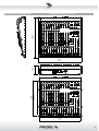
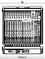
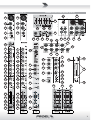
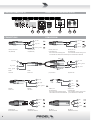
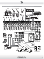


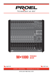

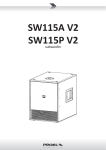
![[ITA] MATRIX Manuale installazione v1-0 lo](http://vs1.manualzilla.com/store/data/006147102_1-fa7918564fa6c545bcfb385c99312d88-150x150.png)