1
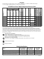
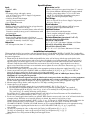
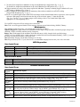
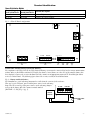
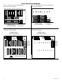
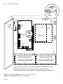
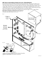
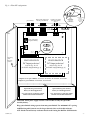
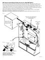
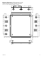
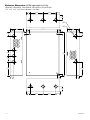
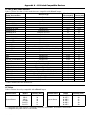
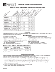
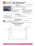
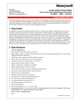
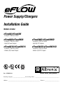
Power Supply/Chargers Installation Guide Models Include: eFlow6N/eFlow6NX - 6 amp @ 12VDC or 24VDC eFlow6N8/eFlow6NX8 eFlow6N8D/eFlow6NX8D eFlow6N16/eFlow6NX16 eFlow6N16D/eFlow6NX16D - 6 amp @ 12VDC or 24VDC - Eight (8) Fused Outputs - 6 amp @ 12VDC or 24VDC - Sixteen (16) Fused Outputs - 6 amp @ 12VDC or 24VDC - Eight (8) PTC Outputs - 6 amp @ 12VDC or 24VDC - Sixteen (16) PTC Outputs Altronix Corp. 140 58th St. Brooklyn, NY Rev. 6NRP052213 More than just power.™ Installing Company: ______________________ Service Rep. Name: ___________________________________________ Address: _________________________________________________________ Phone #: __________________________ Overview: The eFlow6N power supply/chargers convert a 120VAC / 60Hz input, to a 12VDC or 24VDC nominal output (see Power Supply Configuration Reference Chart and Specifications). eFlow6N eFlow6NX eFlow6N8 eFlow6NX8 eFlow6N8D eFlow6NX8D eFlow6N16 eFlow6NX16 eFlow6N16D eFlow6NX16D 10.0-13.2 20.19-26.4 10.03-13.2 20.19-26.4 6 3.5A 5A/250V 10A/32V 910 N/A 1 10.0-13.2 20.19-26.4 10.03-13.2 20.19-26.4 6 3.5A 5A/250V 10A/32V 910 PD8UL 8 9.78-13.2 20.0-26.4 10.03-13.2 20.19-26.4 6 3.5A 5A/250V 10A/32V 910 PD8ULCB 8 10.0-13.2 20.19-26.4 10.03-13.2 20.19-26.4 6 3.5A 5A/250V 10A/32V 910 9.78-13.2 20.0-26.4 10.03-13.2 20.19-26.4 6 3.5A 5A/250V 10A/32V 910 PD16W 16 2 - PD8UL PD16WCB 16 2 - PD8ULCB – – 2.5A 2.5A – – 2.5A 2.5A – – – – – – 2A 2A – – 2A 2A Accommodates up to 7AH Batteries Accommodates up to 12AH Batteries PTC Output Ratings Fused Output Ratings Number of Outputs Power Distribution Modiule Under low battery condition Ripple Voltage (mV) Battery Fuse Rating 24VDC Output Range (volts) [AUX] 12VDC Output Range (volts) 24VDC Output Range (volts) Altronix Model Number 12VDC Output Range (volts) [DC] Input Rating: 120VAC, 60Hz Input Fuse Rating Nominal DC Outputs Maximum Supply Current for Main and Aux. Outputs (amp) eFlow6N Series Power Supply Configuration Reference Chart: 3 – 3 – 3 – 3 – 3 – – 3 – 3 – 3 – 3 – 3 These units provide non power-limited outputs: eFlow6N, eFlow6NX, eFlow6N8, eFlow6NX8, eFlow6N16 and eFlow6NX16. These units provide power-limited outputs: eFlow6N8D, eFlow6NX8D, eFlow6N16D and eFlow6NX16D. If a power-limited output is required in the end-product application, the DC output from the power supply must be connected to a separately Listed control unit or accessory board that provides power-limited outputs. The product(s) providing the power-limited output(s) must be listed as appropriate for the particular end-product application (fire alarm, burglar alarm, access control), and wired in accordance with the products installation instructions. Class 1 wiring methods, separation of circuits, and proper fire-rated enclosures all must be considered when connecting the DC output of the power supply to the end-product devices. The auxiliary output of these units are power-limited. UL Listings for US Installations: UL 294 - UL Listed for Access Control System Units. UL 603 - UL Listed for Power Supplies for Use with Burglar-Alarms Systems. UL 1481 - UL Listed for Power Supplies for Fire Protective Signaling Systems. UL Listings for Canadian Installations: ULC-S318-96 - Power Supplies for Burglar Alarm Systems. Also suitable for Access Control. Altronix Corp. California State Fire Marshal 140 58th St. Brooklyn, NY European Conformity Stand-by Specifications: Battery 7AH 12AH 40AH (for eFlow6NX refer to Fig. 8, pg. 10) 65AH (for eFlow6NX refer to Fig. 8, pg. 10) - 2 - Burg. Applications 4 hr. Stand-by/ 15 min. Alarm 0.4 amp/6 amp 1 amp/6 amp 6 amp/6 amp 6 amp/6 amp Fire Applications 24 hr. Stand-by/ 5 min. Alarm N/A 0.3 amp/6 amp 1.2 amp/6 amp 1.5 amp/6 amp Access Control Applications Stand-by 10 Mins./6 amp 25 Mins./6 amp Over 4 Hours/6 amp Over 4 Hours/6 amp eFlow6N Series Input: • 120VAC, 60Hz. Specifications: Supervision (cont’d): Output: • For output voltage and supply current, refer to eFlow6N series Power Supply Configuration Reference Chart, pg. 2. • Auxiliary Power-Limited output rated @ 1 amp (unswitched). • Over Voltage Protection. Battery Backup: • Built-in charger for sealed lead acid or gel type batteries. • Maximum charge current 1.54 amp. • Automatic switch over to stand-by battery when AC fails. Transfer to stand-by battery power is instantaneous with no interruption. Fire Alarm Disconnect: • Supervised Fire Alarm disconnect (latching or non-latching) 10K EOL resistor. Operates on a normally open (NO) or normally closed (NC) trigger. Supervision: • AC fail supervision (form “C” contacts). • Battery fail & presence supervision (form “C” contacts). • Low power shutdown. Shuts down DC output terminals if battery voltage drops below 71-73% for 12V units and 70-75% for 24V units (depending on the power supply). Prevents deep battery discharge. Fuse Ratings: • Refer to eFlow6N Series Power Supply Configuration Reference Chart, pg. 2. Visual Indicators: • Green AC Power LED indicates 120VAC present. • AC input and DC output LED indicators. Additional Features: • Short circuit and overload protection. • Unit is complete with power supply, enclosure, battery leads and cam lock. Enclosure Dimensions (approximate H x W x D): eFlow6N, eFlow6N8, eFlow6N8D, eFlow6N16, eFlow6N16D: 13.5” x 13” x 3.25” (342.9mm x 330.2mm x 82.55mm) eFlow6NX, eFlow6NX8, eFlow6NX8D, eFlow6NX16, eFlow6NX16D: 15.5” x 12” x 4.5” (393.7mm x 304.8mm x 114.3mm) Installation Instructions: Wiring methods shall be in accordance with the National Electrical Code/NFPA 70/NFPA 72/ANSI, The Canadian Electrical Code, Part 1 and with all local codes and authorities having jurisdiction. The product must be located indoors within the protected premises. 1. Mount unit in the desired location. Mark and predrill holes in the wall to line up with the top two keyholes in the enclosure. Install two upper fasteners and screws in the wall with the screw heads protruding. Place the enclosure’s upper keyholes over the two upper screws, level and secure. Mark the position of the lower two holes. Remove the enclosure. Drill the lower holes and install the two fasteners. Place the enclosure’s upper keyholes over the two upper screws. Install the two lower screws and make sure to tighten all screws (Enclosure Dimensions, pgs. 11-12). Secure enclosure to earth ground. 2. Set desired DC output voltage by setting SW1 to the appropriate position on the power supply board (Fig. 1i, pg. 5). 3. Connect unswitched AC power (120VAC 60Hz) to terminals marked [L, N] (Fig. 1a, pg. 5). Use 14 AWG or larger for all power connections. Secure green wire lead to earth ground. Keep power-limited wiring separate from non power-limited wiring (120VAC 60Hz Input, Battery Wires). Minimum 0.25” spacing must be provided. CAUTION: Do not touch exposed metal parts. Shut branch circuit power before installing or servicing equipment. There are no user serviceable parts inside. Refer installation and servicing to qualified service personnel. For Fire Alarm applications the outputs are “Special Applications” only, see list (refer to Appendix A, pg. 12). 4. Measure output voltage before connecting devices. This helps avoiding potential damage. 5. Connect devices to be powered: a. For eFlow6N/eFlow6NX connect devices to terminals marked [- DC +] (Fig. 1h, pg. 3). b. For other Power Distribution Models connect devices to be powered to terminal pairs 1 to 8 marked [1P & 1N] through [8P & 8N] (Fig. 3a & 3b, pg. 6) or 1 to 16 marked [1P & 1N] through [16P & 16N] (Fig. 4a & 4b, pg. 6) carefully observing correct polarity. For auxiliary device connection this output will not be affected by Low Power Disconnect or Fire Alarm Interface. Connect device to terminals marked [+ AUX -- ] (Fig. 1f, pg. 5). 6. For Access Control applications batteries are optional. When batteries are not used, a loss of AC will result in the loss of output voltage. When the use of stand-by batteries is desired, they must be lead acid or gel type. Connect battery to terminals marked [-- BAT + ] (Fig. 1g, pg. 5). Use two (2) 12VDC batteries connected in series for 24VDC operation (battery leads included). Use batteries - Casil CL1270 (12V/7AH), CL12120 (12V/12AH), CL12400 (12V/40AH), CL12650 (12V/65AH) batteries or UL recognized BAZR2 batteries of an appropriate rating. 7. Connect appropriate signaling notification devices to AC FAIL & BAT FAIL (Fig. 1b, pg. 5) supervisory relay outputs. 8. To delay AC reporting for 2 hrs. set dip switch [AC Delay] to OFF position (Fig. 1c, pg. 5). To delay AC reporting for 1 min. set dip switch [AC Delay] to ON position (Fig. 1c, pg. 5). Note: Must be set to ON position for Burglar Alarm Applications. eFlow6N Series -3- 9. To enable Low Output Power Shutdown set dip switch [Shutdown] to ON position (Fig. 1c, pg. 5). To disable Low Output Power Shutdown set dip switch Shutdown] to OFF position (Fig. 1c, pg. 5). 10.Trigger terminals are end of a line resistor supervised (10k ohms). Opening or shorting trigger terminals will cause [DC] output to shutdown (Fig. 1d, pg. 5). 11.Place a jumper for non-latching FACP. A momentary short on these terminals resets FACP latching [Trigger EOL Shutdown] (Fig. 1e, pg. 5). 12.For Access Control Applications: mount UL Listed tamper switch (Sentrol model 3012 or equivalent) at the top of the enclosure. Slide tamper switch bracket onto the edge or the enclosure approx. 2” from the right side (Fig. 5, pg. 7 or Fig. 7, pg. 9). Connect tamper switch wiring to the Access Control Panel input or the appropriate UL Listed reporting device. Wiring: Use 18 AWG or larger for all low voltage power connections. Note: Take care to keep power-limited circuits separate from non power-limited wiring (120VAC, Battery). Maintenance: Unit should be tested at least once a year for the proper operation as follows: Output Voltage Test: Under normal load conditions, the DC output voltage should be checked for proper voltage level eFlow6N: 12VDC or 24VDC nominal rated @ 6 amp max. Battery Test: Under normal load conditions check that the battery is fully charged, check specified voltage (12VDC @ 13.2 or 24VDC @ 26.4) both at the battery terminal and at the board terminals marked [-- BAT + ] to ensure that there is no break in the battery connection wires. Note: Maximum charging current under discharges is 1.54 amp. Note: Expected battery life is 5 years, however it is recommended changing batteries in 4 years or less if needed. LED Diagnostics: Power Supply/Charger Red (DC) ON ON OFF OFF Green (AC/AC1) ON OFF ON OFF Power Supply Status Normal operating condition. Loss of AC, Stand-by battery supplying power. No DC output. Loss of AC. Discharged or no stand-by battery. No DC output. Power Distribution Module Green (AC) Power Distribution Module Status ON Normal operating condition. OFF No Power Output. Terminal Identification: Power Supply/Charger Terminal Legend L, N – DC + Trigger EOL Supervised NO, GND RESET + AUX – AC Fail NC, C, NO Bat Fail NC, C, NO – BAT + - 4 - Function/Description Connect 120VAC 60Hz to these terminals: L to hot, N to neutral (non power-limited) (Fig. 1a, pg.5). 12VDC or 24VDC nominal @ 6 amp continuous output (non power-limited output) (Fig. 1h, pg. 5). Fire Alarm Interface trigger input from a short or FACP. Trigger inputs can be normally open, normally closed from an FACP output circuit (power-limited input) (Fig. 1d, pg. 5). FACP interface latching or non-latching (power-limited) (Fig. 1e, pg. 5). Auxiliary Power-Limited output rated @ 1 amp (unswitched) (power-limited output) (Fig. 1f, pg. 5). Indicates loss of AC power, e.g. connect to audible device or alarm panel. Relay normally energized when AC power is present. Contact rating 1 amp @ 30VDC (power-limited) (Fig. 1b, pg. 5). Indicates low battery condition, e.g. connect to alarm panel. Relay normally energized when DC power is present. Contact rating 1 amp @ 30VDC. A removed battery is reported within 5 minutes. Battery reconnection is reported within 1 minute (power-limited) (Fig. 1b, pg. 5). Stand-by battery connections. Maximum charge current 1.54 amp (non power-limited) (Fig. 1g, pg. 5). eFlow6N Series Terminal Identification: Power Distribution Module Terminal Legend PD8UL/PD8ULCB 1P to 8P 1N to 8N Terminal Legend Function/Description PD16W/PD16WCB 1P to 16P Positive DC power outputs. 1N to 16N Negative DC power outputs. Fig. 1 - eFlow6N Board configuration OPEN --- 24V CLOSED --- 12V AC1 5A 250V L G 1a N AC FAIL BAT FAIL --- DC + 1h --- BAT + 1i 1g AC DELAY SHUTDOWN O N NC C NO NC C NO AC DC 1b 1 min. 2 hr. enable disable 1c TRIGGER EOL SUPERVISED NO GND RESET 1d + AUX – 1e 1f Trouble/Time Limited Warning of Stand-by Batteries: For compliance with ULC S318-96, the Time Limited Warning circuit must be connected for local or remote annunciation with an Amber or Red LED to indicate DC Trouble (low battery, loss of battery or when 95% of the stand-by battery has been depleted). Connect the circuit to the Batt Fail relay contacts to an appropriate input of a UL Listed Burglar Alarm or Access Control Panel. The following figure shows the circuitry needed for local annunciation. Fig. 2 - Battery trouble indication For Canadian use, a red indicating lamp must be visible from the exterior of this enclosure. Wire one leg of a UL Listed, power-limited power source to the indicating lamp. Wire the second leg of the power source to the indicating lamp in AC FAIL BAT FAIL series with the battery fail relay contact terminals marked [BAT FAIL - C, NO] (Fig. 2, pg. 5). POWER SOURCE NC C NO NC C NO RED INDICATING LAMP eFlow6N Series -5- Power Distribution Module(s): Fig. 3a - PD8UL Power Distribution Board Non Power-Limited Outputs Fig. 3b - PD8ULCB - Power Distribution Board Power-Limited Outputs Replace fuses with the same type and rating 3.5A, 250V. 1 6 7 8 P N POWER OUTPUTS POWER R1 INPUT OUTPUTS DC Output to devices 1P-8P Power Outputs, 1N-8N Common Outputs ( ) COMMON POWER LED R1 INPUT OUTPUTS ) 1 2 3 4 5 6 7 8 9 10 11 12 13 14 15 16 N From Power Supply Board (Factory Installed) ) common outputs protected outputs P N P P S - 6 - 8 OUTPUTS ( Input 3.5A 250V 7 DC Output to devices 1P-16P Power Outputs, 1N-16N Common Outputs 9 10 11 12 13 14 15 16 N P N N protected outputs 6 Fig. 4b - PD16WCB - Power Distribution Board Power-Limited Outputs ) common outputs POWER ( DC Output to devices 1P-16P Power Outputs, 1N-16N Common Outputs 1 2 3 4 5 6 7 8 5 DC Output to devices 1P-8P Power Outputs, 1N-8N Common Outputs From Power Supply Board (Factory Installed) Fig. 4a - PD16W Power Distribution Board Non Power-Limited Outputs ( 4 LED N COMMON 3 D1 FUSED D1 FUSED 2 P From Power Supply Board (Factory Installed) N 5 P 4 P 3 S 2 From Power Supply Board (Factory Installed) Input 1 For continuous protection against risk of fire replace fuses with same type and rating. eFlow6N Series Fig. 5 - eFlow6N configuration Edge of Enclosure Enclosure to Access Control Panel or U.L. Listed Reporting Device 5A 250V Sentrol model # 3012 Tamper Switch or equivalent (Not Included) Wire Strap (from Enclosure to Door) Green Lead (ground) L 120VAC power mains Non Powerlimited G N Door AC FAIL C NO BAT FAIL NC C NO PD16W/ PD16WCB Switch Detail AC1 NC PD8UL/PD8ULCB Battery & AC Supervision Circuit (Power-limited) OPEN 24V DC Output to devices* CLOSED 12V AC (refer to Fig. 3a, 3b, 4a or 4b for board configuration pg. 6) OPEN --- 24V CLOSED --- 12V RESET GND NO – AUX + Powerlimited TRIGGER EOL disable SUPERVISED enable O N 2 hr. 1 min. DC AC DELAY SHUTDOWN Battery Connections (Non Power-limited) --- BAT + --- DC + Optional Rechargeable Stand-by Battery for UL294 Applications. Optional Rechargeable Stand-by Battery for UL294 Applications. Note: 12V batteries required for UL603, UL1481 and Canadian installations. Note: 12V batteries required for UL603, UL1481 and Canadian installations. CAUTION: When power supply board is set for 12VDC use only one (1) 12VDC stand-by battery. Keep power-limited wiring separate from non power-limited. Use minimum 0.25" spacing. 7AH Rechargeable batteries are the largest batteries that can fit in this enclosure. A UL Listed external battery enclosure must be used if using 12AH, 40AH or 65AH batteries. *Outputs are non power-limited: eFlow6N, eFlow6N8, eFlow6N16. Outputs are power-limited: eFlow6N8D, eFlow6N16D. eFlow6N Series -7- NEC Power-Limited Wiring Requirements for eFlow6N Models: Power-limited and non power-limited circuit wiring must remain separated in the cabinet. All power-limited circuit wiring must remain at least 0.25” away from any non power-limited circuit wiring. Furthermore, all power-limited circuit wiring and non power-limited circuit wiring must enter and exit the cabinet through different conduits. One such example of this is shown below. Your specific application may require different conduit knockouts to be used. Any conduit knockouts may be used. For power-limited applications, use of conduit is optional. All field wiring connections must be made employing suitable gauge CM or FPL jacketed wire (or equivalent substitute). Optional UL Listed battery enclosure must be mounted adjacent to the power supply via Class 1 wiring methods. For Canadian installations use shielded wiring for all connections. Note: Refer to wire handling drawing below for the proper way to install the CM or FPL jacketed wire, (Fig, 7a). Fig. 7 120VAC Input 60Hz (non powerlimited) Optional UL Listed Battery Enclosure (non power-limited) Supervisory, Fire Alarm Interface & Aux. output Connections (power-limited) Power Distribution DC Outputs* Fig. 7a Incorrect Wire Handling Correct Wire Handling External Jacketed Shield Battery Connections (non power-limited) Wire Insulation Solid Copper Conductors Pull back external jacketed shield approx. 1/2”. *Outputs are non power-limited: eFlow6N, eFlow6N8, eFlow6N16. Outputs are power-limited: eFlow6N8D, eFlow6N16D. - 8 - eFlow6N Series Fig. 8 - eFlow6NX configuration Edge of Enclosure Enclosure Battery & AC Supervision Circuit (power-limited) power-limited Sentrol model # 3012 Tamper Switch or equivalent (Not Included) 120VAC power mains (non power-limited) Class 1 to Access Control Panel or U.L. Listed Reporting Device L AC1 AC FAIL G C BAT FAIL NO AC DC AC DELAY SHUTDOWN O N NC 2 hr. 1 min. C TRIGGER EOL disable SUPERVISED enable NC RESET GND NO NO – AUX + Door N Green Lead (ground) 5A 250V --- BAT + Battery connections (non power-limited) Switch Detail --- DC + OPEN 24V CLOSED 12V OPEN --- 24V CLOSED --- 12V Wire Strap (from Enclosure to Door) PD8UL/PD8ULCB PD8UL/PD8ULCB DC Output to devices* DC Output to devices* (refer to Fig. 3a, 3b for board configuration pg. 6) (refer to Fig. 3a, 3b for board configuration pg. 6) *Outputs are non power-limited: eFlow6NX, eFlow6NX8, eFlow6NX8D, eFlow6NX16. Outputs are power-limited: eFlow6NX8D, eFlow6NX16D. Optional Rechargeable Stand-by Battery for UL294 Applications. Optional Rechargeable Stand-by Battery for UL294 Applications. Note: 12V batteries required for UL603, UL1481 and Canadian installations. Note: 12V batteries required for UL603, UL1481 and Canadian installations. CAUTION: When power supply board is set for 12VDC use only one (1) 12VDC stand-by battery. Keep power-limited wiring separate from non power-limited. Use minimum 0.25" spacing. 12AH Rechargeable batteries are the largest batteries that can fit in this enclosure. A UL Listed external battery enclosure must be used if using the 40AH or 65AH batteries. eFlow6N Series -9- NEC Power-Limited Wiring Requirements for eFlow6NX Models: Power-limited and non power-limited circuit wiring must remain separated in the cabinet. All power-limited circuit wiring must remain at least 0.25” away from any non power-limited circuit wiring. Furthermore, all power-limited circuit wiring and non power-limited circuit wiring must enter and exit the cabinet through different conduits. One such example of this is shown below. Your specific application may require different conduit knockouts to be used. Any conduit knockouts may be used. For power-limited applications, use of conduit is optional. All field wiring connections must be made employing suitable gauge CM or FPL jacketed wire (or equivalent substitute). Optional UL Listed battery enclosure must be mounted adjacent to the power supply via Class 1 wiring methods. For Canadian installations use shielded wiring for all connections. Note: Refer to wire handling drawing below for the proper way to install the CM or FPL jacketed wire, (Fig, 9a). Fig. 9 Supervisory, Fire Alarm Interface & Aux. output Connections (power-limited) Optional UL Listed Battery Enclosure (non power-limited) 120VAC Input 60Hz (non powerlimited) Power Distribution DC Output* Fig. 9a Incorrect Wire Handling Correct Wire Handling Battery Connections (non powerlimited) External Jacketed Shield Wire Insulation Solid Copper Conductors Pull back external jacketed shield approx. 1/2”. *Outputs are non power-limited: eFlow6NX, eFlow6NX8, eFlow6NX16. Outputs are power-limited: eFlow6NX8D, eFlow6NX16D. - 10 - eFlow6N Series Enclosure Dimensions (BC300) (approximate H x W x D): eFlow6N, eFlow6N8, eFlow6N8D, eFlow6N16, eFlow6N16D 13.5” x 13” x 3.25” (342.9mm x 330.2mm x 82.55mm) 1.40” (36mm) 4.85” (123mm) 4.85” (123mm) 1.40” (36mm) 1.20” (31mm) 3.25” (83mm) 1.20” (31mm) 0.75” (19mm) 12.5” (318mm) 11.0” (279mm) 1.20” (31mm) 0.75” (19mm) 0.9375” (24mm) 1.40” (36mm) 1.40” (36mm) 5.10” (130mm) 5.10” (130mm) 13.0” (330mm) 5.10” (130mm) 6.5625” (167mm) 0.9375” (24mm) 3.25” (83mm) 3.25” (83mm) 3.25” (83mm) 1.0” (25mm) 1.0” (25mm) 1.0” (25mm) eFlow6N Series 10.5” (267mm) 1.0” (25mm) - 11 - Enclosure Dimensions (BC400) (approximate H x W x D): eFlow6NX, eFlow6NX8, eFlow6NX8D, eFlow6NX16, eFlow6NX16D 15.5” x 12” x 4.5” (393.7mm x 304.8mm x 114.3mm) 1.5” (38.1mm) 4.615” (117.22mm) 4.615” (117.22mm) 1.5” (38.1mm) 1.75” (44.45mm) 1.375” (34.925mm) 1.125” (28.575mm) 1.25” (31.75mm) 4.5” (114.3mm) 12.23” (310.64mm) 1.1” (27.94mm) 0.91” (23.114mm) 1.5” (38.1mm) 4.5” (114.3mm) 1.1” (27.94mm) 1.25” (31.75mm) 0.91” (23.114mm) 2.0” (50.8mm) 1.5” (38.1mm) 15.5” (393.7mm) 2.0” (50.8mm) 5.0” (127.0mm) 5.0” (127.0mm) 1.1” (27.94mm) 1.25” (31.75mm) 0.79” (20.06mm) 1.25” (31.75mm) 1.75” (44.45mm) 1.5” (38.1mm) - 12 - 4.615” (117.22mm) 4.615” (117.22mm) 1.5” (38.1mm) eFlow6N Series Appendix A - UL Listed Compatible Devices A.1 Four (4) Wire Smoke Detectors Table A-1 below lists four (4) wire smoke detectors compatible with eFlow6N output. System Sensor Smoke Detector/Base B112LP B114LP B404B DH100ACDC DH100ACDCLP DH100ACDCLPW DH400ACDCI DH400ACDCP 1112/24/D 1424 1451 (w/B402B Base) 2112/24ATR 2112/24AITR 2112/24/D 2112/24T/D 2112/24TSRB 2312/24TB 2412 (12 volt) 2424 2451 2451TH (with/B402B Base) 2W-MOD 4W-B (12/24 volt) 4WT-B (12/24 volt) 4WTA-B (12/24 volt) 4WTR-B (12/24 volt) 4WITAR-B (12/24 volt) 2W-MOD2 RRS-MOD 6424 Beam 1224(S) Detector Type Base Base Base Photoelectric Photoelectric Photoelectric Ionization Duct Photoelectric Duct Ionization Ionization Ionization Photoelectric Photoelectric Photoelectric Photoelectric w/135 Thermal Photoelectric w/135 Thermal Supervisory Relay Photoelectric Photoelectric Photoelectric Photoelectric Photoelectric Loop Test/Maintenance Mod. Photoelectric I3 Photoelectric I3 w/Therm I3 Photo w/Therm/Sounder I3 Photo w/Therm/Relay 3 I Photo w/Isolated Therm/Sounder/Relay I3 Loop Test/Maintenance Mod. I3 Reversing Relay/Sync Module Projected Beam Projected Beam o o Max Stand-by Alarm Current (mA) Current (mA) 0.12 36 * * * * 0.15 0.70 0.15 0.70 0.15 0.70 25 95 25 95 0.05 50 0.10 41 0.10 39 0.50 60/70 0.50 60/70 0.05 50 0.05 50 15 45 0.12 50 0.12 77 0.10 41 0.10 39 0.10 39 30 50 .05 23 .05 23 .05 35 .05 35 .05 50 .05 * .05 * 10 28.4 17 38.5 * Contact manufacturer for current draws. A.2 Relays Table A-2 below lists relays compatible with eFlow6N output. Manufacturer System Sensor Model PR-1** PR-2* PR-3* EOLR-1 R-10T** R-14T** Current (mA) 15 30 30 30 23 23 Manufacturer Model Current (mA) System Sensor R-20T** R-24T** R-10E** R-14E** R-20E** R-24E** 40 40 23 23 40 40 * Compatible only with eFlow6N, eFlow6NX, eFlow6N8, eFlow6NX8, eFlow6N16, eFlow6NX16. ** Compatible only when unit is set for 24VDC. eFlow6N Series - 13 - Notes: - 14 - eFlow6N Series Notes: Altronix is not responsible for any typographical errors. Product specifications are subject to change without notice. 140 58th Street, Brooklyn, New York 11220 USA, 718-567-8181, fax: 718-567-9056 website: www.altronix.com, e-mail: [email protected], Made in U.S.A. IIeFlow6N Series eFlow6N Series F06N MEMBER - 15 - Power Supply/Chargers Operating Guide Models Include: Input 120VAC, 60Hz Model Output 12VDC 24VDC Auxiliary Power-Limited Output (unswitched) Ripple Voltage 1 amp 910mV eFlow6N, eFlow6N8, eFlow6N8D, eFlow6N16, eFlow6N16D 3.5 amp 6 amp 6 amp eFlow6NX, eFlow6NX8, eFlow6NX8D, eFlow6NX16, eFlow6NX16D Overview: The eFlow6N series power supply/chargers convert a 120VAC, 60Hz input, to a 12VDC or 24VDC output. Stand-by Specifications: Battery Fire Applications 24 hr. Stand-by/5 min. Alarm Access Control Applications Stand-by 0.4 amp/6 amp 1 amp/6 amp 6 amp/6 amp 6 amp/6 amp N/A 0.3 amp/6 amp 1.2 amp/6 amp 1.5 amp/6 amp 10 Mins./6 amp 25 Mins./6 amp Over 4 Hours/6 amp Over 4 Hours/6 amp Battery Backup: • Built-in charger for sealed lead acid or gel type batteries. • Maximum charge current 1.54 amp. • Automatic switch over to stand-by battery when AC fails. Transfer to stand-by battery power is instantaneous with no interruption. LED Diagnostics: Red (DC) ON ON OFF OFF Green (AC/AC1) ON OFF ON OFF Power Supply Status Normal operating condition. Loss of AC, Stand-by battery supplying power. No DC output. Loss of AC. Discharged or no stand-by battery. No DC output. Installing Company: __________________________________ Service Rep. Name: ____________________________________________________ Address: ________________________________________________________________________ Phone #: ________________________________ Refer to the eFlow Power Supply/Chargers Installation Guide: IIeFlow6N Series, Rev. 6NRP052213 for complete instructions. This sheet is to be removed, framed and posted next to the unit. Rev. 6NRP052213 CUT ALONG DOTTED LINE 7AH 12AH 40AH 65AH Burg. Applications 4 hr. Stand-by/15 min. Alarm