1
iScrub 20
Operating instructions (ENG)
MODELS: CS20
10061250
CSC20
10061330
Read these instructions before using the machine.
86333220-U
05/04/10
Machine Data Log/Overview
OVERVIEW
The Chariot Scrubber is a battery powered, stand-on, hard floor scrubber intended for commercial use. The
appliance applies a cleaning solution onto a hard floor, scrubs the floor with brush or pad, and then vacuums the
soiled water back into the recovery tank.
2
86333220 CS20
Table of Contents
Machine Data Log/Overview. . . . . . . . . . . . . . . . . . . 2
Table of Contents . . . . . . . . . . . . . . . . . . . . . . . . . . . 3
How to Use This Manual . . . . . . . . . . . . . . . . . . . . . . 4
Safety
IMPORTANT SAFETY INSTRUCTIONS . . . . . . . . . 5
HAZARD INTENSITY LEVEL . . . . . . . . . . . . . . . . . . 6
Safety Label Locations . . . . . . . . . . . . . . . . . . . . . . . 7
Operations
Technical Specifications . . . . . . . . . . . . . . . . . . . . . . 8
How This Machine Works . . . . . . . . . . . . . . . . . . . . 10
Components . . . . . . . . . . . . . . . . . . . . . . . . . . . . . . 11
Drive Controls . . . . . . . . . . . . . . . . . . . . . . . . . . . . . 12
Scrub Controls . . . . . . . . . . . . . . . . . . . . . . . . . . . . 16
Scrub Controls-Squeegee. . . . . . . . . . . . . . . . . . . . 18
Pre-Run Machine Inspection. . . . . . . . . . . . . . . . . . 20
Starting Machine . . . . . . . . . . . . . . . . . . . . . . . . . . . 20
Emergency Stop Procedures . . . . . . . . . . . . . . . . . 20
Filling Solution Tank . . . . . . . . . . . . . . . . . . . . . . . . 20
Normal Scrubbing . . . . . . . . . . . . . . . . . . . . . . . . . . 21
To Begin Scrubbing . . . . . . . . . . . . . . . . . . . . . . . . 21
To Stop Scrubbing . . . . . . . . . . . . . . . . . . . . . . . . . 22
Double Scrub . . . . . . . . . . . . . . . . . . . . . . . . . . . . . 22
Emptying and Cleaning Tanks . . . . . . . . . . . . . . . . 23
Maintenance
Service Schedule . . . . . . . . . . . . . . . . . . . . . . . . . . 24
Batteries . . . . . . . . . . . . . . . . . . . . . . . . . . . . . . . . . 25
Battery Charger Programming . . . . . . . . . . . . . . . . 29
Squeegee Blades . . . . . . . . . . . . . . . . . . . . . . . . . . 31
To Remove Squeegee Assembly . . . . . . . . . . . . . . 31
Scrub Brush . . . . . . . . . . . . . . . . . . . . . . . . . . . . . . 31
Finished Floors . . . . . . . . . . . . . . . . . . . . . . . . . . . . 31
Scrub Deck . . . . . . . . . . . . . . . . . . . . . . . . . . . . . . . 32
To Replace Scrub Brush Motor. . . . . . . . . . . . . . . . 33
Scrub Deck Actuator Removal / Replacement . . . .34
Circuit Protection. . . . . . . . . . . . . . . . . . . . . . . . . . .35
Solution . . . . . . . . . . . . . . . . . . . . . . . . . . . . . . . . . .36
Tank Assembly Removal . . . . . . . . . . . . . . . . . . . .38
Drive Unit Removal . . . . . . . . . . . . . . . . . . . . . . . . .39
Vacuum & Float Shutoff . . . . . . . . . . . . . . . . . . . . .40
Vacuum Motor Carbon Brush Replacement . . . . . .41
Drive Motor . . . . . . . . . . . . . . . . . . . . . . . . . . . . . . .42
Drive Motor Carbon Brush Replacement . . . . . . . .42
Drive Chain Tension . . . . . . . . . . . . . . . . . . . . . . . .42
Transporting . . . . . . . . . . . . . . . . . . . . . . . . . . . . . .42
Inclines . . . . . . . . . . . . . . . . . . . . . . . . . . . . . . . . . .43
Troubleshooting . . . . . . . . . . . . . . . . . . . . . . . . . . .44
Battery Discharge Indicator Troubleshooting . . . . .46
Parts
Bumper . . . . . . . . . . . . . . . . . . . . . . . . . . . . . . . . .
Console . . . . . . . . . . . . . . . . . . . . . . . . . . . . . . . . .
Control Panel . . . . . . . . . . . . . . . . . . . . . . . . . . . .
Decals . . . . . . . . . . . . . . . . . . . . . . . . . . . . . . . . . .
Drive-Lower. . . . . . . . . . . . . . . . . . . . . . . . . . . . . .
Drive-Chain . . . . . . . . . . . . . . . . . . . . . . . . . . . . . .
Drive Mounting . . . . . . . . . . . . . . . . . . . . . . . . . . .
Frame & Rear Wheels . . . . . . . . . . . . . . . . . . . . .
Pedal Platform . . . . . . . . . . . . . . . . . . . . . . . . . . .
Pedal Platform Mounting. . . . . . . . . . . . . . . . . . . .
Recovery Tank . . . . . . . . . . . . . . . . . . . . . . . . . . .
Scrub Brush/Pad Driver . . . . . . . . . . . . . . . . . . . .
Scrub Brush Deck . . . . . . . . . . . . . . . . . . . . . . . . .
Scrub Brush Deck Mounting . . . . . . . . . . . . . . . . .
Scrub Deck Lift . . . . . . . . . . . . . . . . . . . . . . . . . . .
Solution Tank . . . . . . . . . . . . . . . . . . . . . . . . . . . .
Squeegee . . . . . . . . . . . . . . . . . . . . . . . . . . . . . . .
Steering. . . . . . . . . . . . . . . . . . . . . . . . . . . . . . . . .
Vacuum . . . . . . . . . . . . . . . . . . . . . . . . . . . . . . . . .
Wiring-Battery . . . . . . . . . . . . . . . . . . . . . . . . . . . .
Wiring-Control Panel . . . . . . . . . . . . . . . . . . . . . . .
Wiring-Main Harness . . . . . . . . . . . . . . . . . . . . . .
Wiring-Diagram . . . . . . . . . . . . . . . . . . . . . . . . . . .
Wiring-Diagram . . . . . . . . . . . . . . . . . . . . . . . . . . .
On Board Battery Charger-Option . . . . . . . . . . . .
Suggested Spare Parts . . . . . . . . . . . . . . . . . . . . .
Serial Numbers . . . . . . . . . . . . . . . . . . . . . . . . . . .
86333220 CS20
48
50
52
54
56
58
60
62
64
66
68
70
72
74
76
78
80
82
84
86
88
90
92
94
96
98
99
3
How to Use This Manual
This manual contains the following sections:
•
•
•
•
•
The SAFETY section contains important information
regarding hazard or unsafe practices of the machine.
Levels of hazards are identified that could
HOW TO USE THIS MANUAL
SAFETY
OPERATIONS
MAINTENANCE
PARTS LIST
result in product or personal injury, or severe injury
resulting in death.
The HOW TO USE THIS MANUAL section will tell you
how to find important information for ordering correct
repair parts.
Parts may be ordered from authorized Windsor
dealers. When placing an order for parts, the machine
model and machine serial number are important. Refer
to the MACHINE DATA box which is filled out during the
installation of your machine. The MACHINE DATA box
is located on the inside of the front cover of this manual.
The OPERATIONS section is to familiarize the operator
with the operation and function of the machine.
The MAINTENANCE section contains preventive maintenance to keep the machine and its components in
good working condition. They are listed in this general
order:
•
•
•
•
•
Batteries
Scrub Brush
Squeegee
Service Schedule
Machine Troubleshooting
The PARTS LIST section contains assembled parts
illustrations and corresponding parts list. The parts lists
include a number of columns of information:
The model and serial number of your machine are
located below the battery compartment of the machine.
REF - column refers to the reference number on
the parts illustration.
PART NO. - column lists the part number for the
part.
PRV NO. - Reference No.
QTY - column lists the quantity of the part used in
that area of the machine.
DESCRIPTION - column is a brief description of
the part.
SERIAL NO. FROM - If this column has an (*) and
a Reference number, see the SERIAL NUMBERS
page in the back of your manual. If column has two
asterisk (**), call manufacturer for serial number.
The serial number indicates the first machine the
part number is applicable to. The main illustration
shows the most current design of the machine.
When a boxed illustration is shown, it displays the
older design.
NOTES - column for information not noted by the
other columns.
NOTE: If a service or option kit is installed on your
machine, be sure to keep the KIT INSTRUCTIONS
which came with the kit. It contains replacement parts
numbers needed for ordering future parts.
NOTE: The number on the lower left corner of the
front cover is the part number for this manual.
4
86333220 CS20
Safety
IMPORTANT SAFETY INSTRUCTIONS
When using an battery powered appliance, basic precaution
must always be followed, including the following:
READ ALL INSTRUCTIONS BEFORE USING THIS MACHINE.
To reduce the risk of fire, electric shock, or injury:
Use only indoors. Do not use outdoors or expose to rain.
Use only as described in this manual. Use only manufacturer's recommended components and attachments.
If the machine is not working properly, has been dropped, damaged, left outdoors, or dropped into water, return it
to an authorized service center.
Do not operate the machine with any openings blocked. Keep openings free of debris that may reduce airflow.
This machine is not suitable for picking up hazardous dust.
Machine can cause a fire when operating near flammable vapors or materials. Do not operate this machine near
flammable fluids, dust or vapors.
This machine is suitable for commercial use, for example in hotels, schools, hospitals, factories, shops
and offices for more than normal housekeeping purposes.
Maintenance and repairs must be done by qualified personnel.
If foam or liquid comes out of machine, switch off immediately.
Disconnect battery before cleaning or servicing.
Before the machine is discarded, the batteries must be removed and properly disposed of.
Make sure all warning and caution labels are legible and properly attached to the machine.
During operation, attention shall be paid to other persons, especially children.
Before use all covers and doors shall be put in the positions specified in the instructions.
When leaving unattended, secure against unintentional movement.
The machine shall only be operated by instructed and authorized persons.
When leaving unattended, switch off or lock the main power switch to prevent unauthorized use.
Only chemicals recommended by the manufacturer shall be used.
This appliance has been designed for use with the brushes specified by the manufacturer. The fitting of other
brushes may affect its safety.
Do not use on surfaces having a gradient of over 10% (6 degrees).
SAVE THESE INSTRUCTIONS
86333220 CS20
5
Safety
The following symbols are used throughout this guide as indicated in their descriptions:
HAZARD INTENSITY LEVEL
There are three levels of hazard intensity identified by signal words -WARNING and CAUTION and FOR SAFETY.
The level of hazard intensity is determined by the following definitions:
WARNING - Hazards or unsafe practices which COULD result in severe personal injury or death.
CAUTION - Hazards or unsafe practices which could result in minor personal injury or product or property damage.
FOR SAFETY: To Identify actions which must be followed for safe operation of equipment.
Report machine damage or faulty operation immediately. Do not use the machine if it is not in proper operating
condition. Following is information that signals some potentially dangerous conditions to the operator or the equipment. Read this information carefully. Know when these conditions can exist. Locate all safety devices on the
machine. Please take the necessary steps to train the machine operating personnel.
FOR SAFETY:
DO NOT OPERATE MACHINE:
Unless Trained and Authorized.
Unless Operation Guide is Read and understood.
In Flammable or Explosive areas.
In areas with possible falling objects.
WHEN SERVICING MACHINE:
Avoid moving parts. Do not wear loose clothing; jackets, shirts, or sleeves when working on the machine. Use
Windsor approved replacement parts.
Batteries emit hydrogen gas. Explosion or fire can result. Keep sparks and open flame away. Keep solution
tank in raised position when charging. Keep sparks and flames away from the batteries. Do not smoke
around batteries.
Disconnect batteries before working on machine. Only qualified personnel should work inside machine.
Always wear eye protection and protective clothing when working on or near batteries. Avoid skin contact
with the acid contained in the batteries.
Never allow metal to lie across battery tops.
6
86333220 CS20
Safety
Safety Label Locations
These drawings indicate the location of safety labels on the machine. If at any time the labels become illegible,
promptly replace them.
86244300
PRV NO. 500955
WARNING LABEL
CAUTION
86244310
PRV NO. 500956
CAUTION LABEL
86335010 (2X)
CAUTION LABEL
86252520
PRV NO. 80885
BATTERY
CAUTION
86333220 CS20
7
Operations
Technical Specifications
ITEM
Nominal power
Rated Voltage
Rated Amperage
Batteries
Battery Compartment Dimensions
Scrub Brush Motor - Disk Machine
Vacuum Motor
Maximum flow rate of vacuum motor
Maximum suction of vacuum motor
Propelling Motor
Mass (GVW)
Weight empty without batteries
Solution Control
Solution capacity
Recovery capacity
Scrub brush diameter - Disk Machine
Scrub brush pressure
Scrub brush speed - Disk Machine
Tires
Maximum Speed
Theoretical Coverage
Brake
Minimum aisle u-turn width
Maximum rated climb and descent angle
8
DIMENSION/CAPACITY
1080 W
36 Volts DC
30 amps
3 X12 Volt 130 AH @ 20 hr. rate
20-1/2 in. x 13 in. x 10 in. tall (330mm x 521mm x 254mm)
1 x .28 HP (209 W)
.63 HP (470 W)
72 cfm (33.98 liters per second)
47.3 inches of water (11.7 kPa)
.21 HP (157 W)
726 lbs (330 kg)
209 lbs (96 kg)
Gravity, 1/3 GPM average
10 gal (38 L)
10 gal (38 L)
20 inch (508 mm)
50 lbs (222N)
180 rpm
8 in. (203mm) drive, 6 in. (156mm) rear, polyurethane
2.7 mph (4.3 Km/hour)
19,800ft²/hr @ 2.5 mph with 2 in. overlap
Electrical parking brake,sets automatically whenever operator
stops.
51in. (1295 mm)
10% (6 degrees)
86333220 CS20
Operations
ITEM
MEASURE
Height
Length
Width without squeegee
Width of squeegee
Width of scrub path
51.8 in (1316mm)
44.0 in (1118mm)
23.4 in (594mm)
27.2 in (691mm)
20 in (508mm)
LENGTH
WIDTH
HEIGHT
SPECIAL NOTES:
The sound pressure level at the operator's ear was
measured to be 66.9 dBA. This was a nearfield, broadband measurement taken in a typical industrial environment on a tile floor. This appliance contains no possible
source of impact noise. The instantaneous sound
pressure level is below 63 Pa.
The weighted root mean square acceleration at the
operator's arms was measured to be below 2.5m/s2.
This was a tri-axial, third-octave-band measurement
made during normal operation on a composite tile floor.
The measurement and related calculations were made
in accordance with ANSI S3.34-1986.
This appliance is not intended for use by persons
(including children) with reduced physical, sensory or
mental capabilities, or lack of experience and knowledge, unless they have been given supervision or
instruction concerning use of the appliance by a person
responsible for their safety. Children should be supervised to ensure that they do not play with the appliance.
86333220 CS20
9
Operations
How This Machine Works
The Chariot® is a battery powered, self-propelled, hard
floor scrubber intended for commercial use. The
appliance applies a cleaning solution onto a hard floor,
scrubs the floor with a brush, and then vacuums the
soiled water back into the recovery tank.
The machine's primary systems are the solution
system, scrub system, recovery system, and operator
control system.
The function of the solution system is to store cleaning
solution and deliver it to the scrub system. The solution
system consists of the solution tank, strainer, metering
valve and solenoid valve. The solution tank stores
cleaning solution (water and detergent) until it is
delivered to the scrub system. The strainer protects the
valves from debris. The solenoid valve automatically
prevents solution flow unless the scrub brush is turned
on and the machine is being propelled.
The function of the scrub system is to scrub the floor.
The disk scrub system consists of one rotary type disk
scrub brush, motor, scrub deck skirt and lift actuator.
The brush scrubs the floor as the motor drives the
brush. The brush drive hub allows the scrub brush to
follow irregularities and changes in the floor without
loosing contact with the floor. The scrub deck skirt
controls the cleaning solution on the floor so that the
squeegee can pick it up.
10
The function of the recovery system is to vacuum the
soiled water back into the recovery tank. The recovery
system consists of the squeegee, vacuum motor, float
ball, recovery tank. The squeegee wipes the dirty
solution off the floor as the machine moves forward.
The vacuum motor provides suction to draw the dirty
solution off the floor and into the recovery tank. The
float ball filter protects the vacuum fan from debris and
foam. The recovery tank stores the dirty solution.
The function of the operator control system is to control
the direction and speed of the machine. The directional
control system consists of the direction control drive
reset switch, throttle pedal, emergency stop/brake
switch, steering wheel, propel controller, and drive
wheel. The directional control drive reset switch signals
forward or reverse direction and makes sure the
operator is on the platform before machine will propel.
The controller interprets signals from the throttle pedal
to command the drive wheel to propel or slow the
machine. The steering wheel points the drive wheel in
the direction desired by the operator. The parking brake
automatically engages when the operator stop the
machine. The emergency stop/brake can be used to
hold the machine on slopes.
86333220 CS20
Operations
Components
7
3
1
10
5
2
6
4
9
11
8
1. Drive Control
7. Recovery Sight Dome
2. Scrub Controls
8. Recovery Drain Hose
3. Control Console
9. Scrub Deck Skirt
4. Pedal Platform
10. Solution Cover
5. Solution Tank
11. Solution Drain Hose/Solution Level Indicator
6. Recovery Tank
86333220 CS20
11
Operations
Drive Controls
1
8
9
5
2
3
7
6
4
10
12
86333220 CS20
Operations
1. Key Switch
6. Steering Wheel
2. Emergency Stop/Brake Switch
7. Speed Control
3. Directional Control / Drive Reset Switch
8. Battery Discharge Indicator
4. Throttle Pedal
9. Hour Meter
5. Horn Button
10. Operator Presence Switch
1. KEY SWITCH
Controls the power for machine functions.
To turn the machine power on, rotate key clockwise.
To turn the machine off, rotate key counterclockwise.
When the key is turned on the battery symbol will flash once and stay on continuously.
2. EMERGENCY STOP/BRAKE SWITCH
This safety feature is designed to cut all power to the machine at any time and apply parking brake.
To shut the machine power off, push the Emergency Stop Switch, this will also engage the parking brake and
cause the machine to stop immediately.
To reset the machine, rotate the switch clockwise.
3. DIRECTIONAL CONTROL / DRIVE RESET SWITCH
This safety feature is designed to ensure safe engagement of propel drive. Each time the machine power is
turned on, or each time an operator steps on to the platform, the Drive Reset Switch must be pushed before
machine will propel.
The switch controls the direction of travel of the vehicle. The lighted arrow on the switch indicates direction of
travel.
To travel forward, press the top of the switch.
To travel in reverse, press the bottom of the switch.
86333220 CS20
13
Operations
4. THROTTLE PEDAL
Controls the speed of the vehicle within the speed control setting selected. Pressing the pedal causes the
machine to travel in the direction selected by the Directional Control Switch.
To increase speed, increase pressure on the pedal.
To decrease speed, decrease pressure on the pedal.
5. HORN BUTTON
The horn is activated by pressing the horn button.
6. STEERING WHEEL
The steering wheel turns the front wheel causing the machine to change direction.
7. SPEED CONTROL
Controls the maximum speed of the machine. There are two settings, slow and fast.
To change speed, rotate the dial to either slow or fast position. The slow position is to the left (counterclockwise), fast to the right (top position).
The throttle pedal will always regulate the speed between 0 and maximum
SLOW
14
FAST
86333220 CS20
Operations
8. BATTERY DISCHARGE INDICATOR
Indicates the charge level of the batteries.
The indicator will be illuminated if the batteries have a sufficient charge. The indicator will flash when the
batteries require charging.
If the batteries are not charged the indicator will turn off and the vacuum, scrub motor and water solenoid will
not function.
When the machine is left overnight with less than a full charge, the display may initially indicate a full charge. It
will also indicate a full charge if the batteries are disconnected, then reconnected. After a few minutes of
operation the indicator will give the correct charge level.
9. HOUR METER
Records the number of hours the machine has been in scrubbing operation. This information is useful in determining when to service the machine.
86333220 CS20
15
Operations
Scrub Controls
1
1. FUNCTION MODE SWITCH
The first two positions are for transport only. See drive controls section.
A1 - Light cleaning
This mode is used for light cleaning. In this mode the machine will propel at fast speed. The ‘floating’ scrub
deck and squeegee is in the down position. The water will flow. Water will automatically shut off in neutral and
restarts when scrubbing is resumed. The vacuum will draw the water into the recovery tank.
A2 - Deep cleaning
This mode is used for deep cleaning. In this mode the machine will propel at a low speed. The ‘floating’ scrub
deck and squeegee is in the down position. The water will flow. Water will automatically shut off in neutral and
restarts when scrubbing is resumed. The vacuum will draw the water into the recovery tank.
16
86333220 CS20
Operations
B - Vacuum only mode
This mode is used for picking up solution only. The brush and water will both be up and off. In this mode the
machine will propel at fast speed. The squeegee is lowered and the vacuum will come on.
C - Double Scrub cleaning
This mode is used for putting down solution and scrubbing without picking it back up. The squeegee is set
manually by connecting the two double scrub support cables. In this mode the machine will propel at a slow
speed. The scrub deck will lower. The solution will flow. The brush and water will shut off when the machine is
in neutral. They will resume when propelling is resumed.
86333220 CS20
17
Operations
Scrub Controls-Squeegee
4
3
2
1. Squeegee Latch
2. Squeegee Hose and Tube
3. Squeegee Wheels (3)
4. Double Scrub Support Cable
5. Double Scrub Cable Hook
18
86333220 CS20
5
1
Operations
1. Squeegee Latch
The squeegee latch holds the squeegee in place.
2. Squeegee Hose and Tube
The squeegee hose and tube carry the recovered solution to the recovery tank.
3. Squeegee Wheels
The three squeegee wheels support the squeegee at the correct height and angle so that no adjustment is
required.
4. Double Scrub Support Cable
The double scrub support cables retain the deck in the double scrub position.
5. Double Scrub Cable Hook
The double scrub cable hook is the connection point for the double scrub support cable.
Since the squeegee is raised and lowered by the scrub deck, the double scrub position is set manually.
86333220 CS20
19
Operations
Machine Operation
Emergency Stop Procedures
Pre-Run Machine Inspection
Do a pre-run inspection to find possible problems that
could cause poor performance or lost time from breakdown. Follow the same procedure each time to avoid
missing steps.
NOTE: See maintenance section for pre-run machine
inspection checklist items.
Push in emergency stop button. This will also engage
the parking brake and cause the machine to stop immediately.
Filling Solution Tank
FOR SAFETY: Before leaving or servicing machine;
stop on level surface, turn off machine and remove
key.
1. Turn the machine power off.
Starting Machine
2. Tilt console forward. Push left or right fill port cover
down.
NOTE: Perform pre-run machine check before
operating machine.
FOR SAFETY: Before starting machine, make sure
that all safety devices are in place and operating
properly.
1. The operator should be on the pedal platform. The
throttle pedal must be in the neutral position.
2. Turn the machine power on by turning key switch
clockwise to the “ON” position.
3. Press the Drive Reset Directional Control Switch to
reset and set the intended direction for travel.
4. Press lightly on the throttle pedal with right foot
3. Fill the solution tank with clean water, leaving
enough room for the required amount of cleaning
solution. The solution tank capacity filled to fill inlet
is 10 gallons (38 liters). The water must not be hotter than 140° F (60°C) to prevent damage to the
tank.
4. Measure the chemical into the solution tank. Liquid
chemicals should be added to the solution tank
after filling with water. Dry chemicals should be
thoroughly mixed before being added into solution
tank. Commercially available, high alkaline floor
cleaners, are suitable for use in the solution system.
NOTE: Read the chemical manufacturers
recommended proportion instructions.
5. Close console and latch rear cover.
Flammable materials can cause an explosion or
fire. Do not use flammable materials in the tanks.
20
86333220 CS20
Operations
Normal Scrubbing
To Begin Scrubbing
Plan the scrubbing pattern in advance. The longest
track is around the perimeter of the area to be cleaned.
For efficient operation, the runs should be the longest
possible without turning, stopping, or raising or
lowering scrub deck/squeegee.
When operating the machine around people, pay
close attention for unexpected movement. Use
extra caution around children.
In order to achieve the best possible results, the area
which is to be cleaned should be swept before scrubbing. Large debris, strings and wire must be removed to
prevent being caught in brushes or squeegee.
If the machine is allowed to stand in neutral with the
scrub deck down, the solutions flow stops and brush
motor stops. If either forward or reverse travel is
selected, the solution flow will continue in the same
setting and the scrub brush motor will continue once
movement of machine begins. Overlap the brush path
and avoid transporting over previously cleaned areas.
Flammable liquids and/or reactive metals can
cause explosions or fire! Do not pick up.
1. Stand on the operator platform. Throttle pedal must
be in neutral position.
2. Turn machine power on.
3. Press the Drive Reset / Directional Control Switch,
selecting the desired travel direction.
4. Position the function control knob to the desired
operation. The scrub deck and squeegee will
lower, and the vacuum will turn on.
5. Drive machine forward to begin scrubbing.The
scrub brush motor will run and solution will flow
when the throttle is depressed.
NOTE: Shut machine off immediately if water or foam
is expelled from the machine. Solution flow is
automatically shut off when brush motor stops. When
brush motor is activated, flow automatically resumes.
86333220 CS20
21
Operations
To Stop Scrubbing
1. Rotate the function knob to either transport position. The brush motor and vacuum will stop and the
scrub deck will rise to the park position.
2. Allow the throttle pedal to return to neutral.
3. Turn machine power off.
NOTE: FOR SAFETY: Before leaving or servicing
machine: stop on level surface, turn off machine
and remove key.
Double Scrub
Floors which are heavily soiled or have thick accumulations of floor finish may not clean sufficiently with one
pass. In these cases it will be necessary to double
scrub.
Rotate the knob to the double scrub position.
Connect the Double Scrub Cables to the squeegee.
To support the squeegee off the floor for double scrub,
pull the support cables down, one side at a time, and
connect to the hook on the squeegee while lifting and
tilting the squeegee upward.
To collect the solution and complete the Double Scrub
operation, release both squeegee cable and turn the
function knob to one of the normal scrubbing modes.
DOUBLE SCRUB
CABLE
DOUBLE SCRUB HOOK
22
86333220 CS20
Operations
Emptying and Cleaning Tanks
Solution Tank
1. Park the machine next to a floor drain. Drain hoses
are at the rear of the machine.
1. Pull the solution drain hose from its mounting
pocket. Lower hose in direction of drain.
2. Turn the machine power off.
2. Open the control console.
Recovery Tank
3. Flush the solution tank out with clean water and
run several gallons of clean water through systems. Do not use water hotter than 140°F (60°C) to
clean tank. Damage may occur.
1. Pull the recovery drain hose from the mounting
pocket. Lift cap, pinch hose then lower hose in
direction of the drain. Do not stand in front of end of
hose. Recovered solution will come out with force.
Never allow solution to remain in tank. Damage to tank,
seals and valves could occur.
2. To flush the recovery tank, lift the control console to
access the recovery tank. Do not use water hotter
than 140°F (60°C) to clean tank. Damage may
occur.
3. Clean debris from sight dome and cover surface.
4. Clean off the float shut-off screen and inspect for
free movement of float.
5. Replace the drain cap and secure drain hose.
6. If machine is to be stored, tilt the recovery tank
back and prop the console up, partially opening
each.
RECOVERY
DRAIN HOSE
SOLUTION
DRAIN HOSE
STORAGE POSITION
86333220 CS20
23
Maintenance
Service Schedule
BEFORE EACH
WORK PERIOD
MAINTENANCE
Check water level of batteries after charging; add
distilled water if necessary. (Wet cell only)
Visually check for damaged or worn tires.
Check brush or pad for proper installation.
Check vacuum hose connections.
Check that squeegee is securely attached.
Check for securely attached drain hoses, plug and cap.
Check pedal, brake and steering for proper operation.
Clean out recovery tank.
Clean and inspect float shutoff.
Clean out solution tank.
Clean and inspect solution filter strainer.
Run vacuum motor to dry.
Clean brush or pad and check wear.
Clean squeegee blades and check wear.
Clean outside of tanks, check for damage.
Store with console cover propped open.
Charge batteries if needed.
Clean off top of batteries.
Check battery cells with hydrometer. (Wet cell only)
Inspect scrub deck skirt.
Clean solution strainer inside tank.
Check battery connections are tight.
Clean battery cases and battery compartment.
Check parking brake.
Clean pivot points on squeegee and scrub deck.
Check all motors for carbon brush wear.
Check motor commutators.
Check steering chain tension.
Check drive chain tension.
24
AFTER EACH
50 100 200
WORK PERIOD HRS HRS HRS
*
*
*
*
*
*
*
86333220 CS20
*
*
*
*
*
*
*
*
*
*
*
*
*
*
*
*
*
*
*
*
*
*
Maintenance
Batteries
1
4
3
2
5
1. Cover Retainer Latch
2. Rear Cover
3. Battery Connector-Machine
4. Batteries
5. Battery Tray
86333220 CS20
25
Maintenance
Batteries (Wet Cell)
The batteries provide the power to operate the
machine. The batteries require regular maintenance to
keep them operating at peak efficiency.
The machine batteries will hold their charge for long
periods of time, but they can only be charged a certain
number of times. To get the greatest life from the
batteries, charge them when their charge level reaches
25% of a full charge. Use a hydrometer to check the
charge level.
Do not allow the batteries to remain in a discharged
condition for any length of time. Never expose a
discharged battery to temperatures below freezing.
Discharged batteries will freeze causing cracked
cases. Do not operate the machine if the batteries are
in poor condition or if they have a charge level below
25% (specific gravity below 1.155).
When servicing machine, avoid contact with
battery acid.
Batteries emit hydrogen gas. Explosion or fire can
result. Keep sparks and open flame away. Keep
covers open when charging.
Wear eye protection and protective clothing when
working with batteries.
Keep all metallic objects off the top of the batteries, as
they may cause a short circuit. Replace worn or
damaged cables and terminals.
Charge batteries in a well ventilated area.
Check the electrolyte level in each battery cell before
and after charging the batteries. Never add acid to the
batteries, use distilled water. Do not allow water level to
fall below the battery plates. Portions of plates exposed
to air will be destroyed. Do not overfill. Keep plugs
firmly in place at all times.
1. When cleaning the batteries, use a solution of
baking soda and water. Do not allow the cleaning
fluid to enter the battery cells, electrolyte will be
neutralized.
Not all batteries require maintenance. AGM
batteries are maintenance free. Do not attempt to
remove sealed caps from AGM batteries. Warranty
is void if caps are removed from AGM battery.
Battery Maintenance
2. Maintain the proper electrolyte level in each battery
cell. If a cell should accidentally overflow, clean
immediately.
3. Wipe off the top of the batteries at least once a
week.
4. Test battery condition with a hydrometer at least
once a week.
5. Ensure that all connections are tight and all
corrosion removed.
6. Every 4 to 6 months, remove the batteries from the
machine and clean the battery cases and battery
compartment.
26
86333220 CS20
Maintenance
Checking Battery Specific Gravity
Charging Batteries
Use a hydrometer to check the battery specific gravity.
When servicing machine, avoid contact with
battery acid.
Batteries emit hydrogen gas. Explosion or fire can
result. Keep sparks and open flame away. Keep
covers open when charging.
Wear eye protection and protective clothing when
working with batteries.
CHECKING GRAVITY
a. Hydrometer Battery
b. Battery
Charge batteries in a well ventilated area.
NOTE: Do not take readings immediately after adding
distilled water, if the water and acid are not thoroughly
mixed, the reading may not be accurate.
Use a 36 volt, 20 amp maximum output DC charger
which will automatically shut off when the batteries are
fully charged.
Check the hydrometer readings against this chart.
1. Stop the machine in a clean, well ventilated area
next to the charger.
SPECIFIC GRAVITY
@ 80° F (27°C)
1.265
1.225
1.190
1.155
1.120
BATTERY CONDITION
100% CHARGED
75% CHARGED
50% CHARGED
25% CHARGED
DISCHARGED
NOTE: If the readings are taken when the battery
electrolyte is any temperature other than 80°F (27°C),
the reading must be temperature corrected.
To find the corrected specific gravity reading when the
temperature of the battery electrolyte is other than 80°F
(27°C): Add (+) to the specific gravity reading 0.004 (4
points), for each 10°F (6°C) above 80° (27°C). Subtract
(-) from the specific reading 0.004 (4 points), for each
10°F (6°C) below 80°F (27°C).
2. Turn “OFF” machine.
FOR SAFETY: Before leaving or servicing machine;
stop on level surface, turn off machine and remove
key.
3. Remove rear cover, unplug batteries from
machine, unlatch battery tray and pull out to
expose batteries.
Batteries emit hydrogen gas. Explosion or fire can
result. Keep sparks and open flame away. Keep
covers open when charging.
4. Check the electrolyte level in each battery cell.
Before charging, add just enough distilled water to
cover the plates. After charging is complete, add
just enough distilled water to bring up the level to
the indicator ring. If the water level is too high
before charging, normal expansion rate of the electrolyte may cause an overflow resulting in a loss of
battery acid balance and damage the machine.
86333220 CS20
27
Maintenance
5. Replace the battery caps, and leave them in place
while charging.
6. Disconnect main positive lead and secure cable
terminals away from batteries.
6. Unplug the battery connector from the machine.
7. Loosen both terminals on each jumper cable and
remove one at a time.
FOR SAFETY: When charging, connect the charger
to the batteries before connecting the charger to
the AC wall outlet. Never connect the charger to the
AC wall outlet first. Hazardous sparks may result.
8. Prepare a suitable site to place the batteries.
7. Plug the charger connector into the battery
connector. Connect the charger AC plug to a wall
outlet. The charger gauge should indicate that the
batteries are charging.
Attach suitable battery lifting device and lift batteries
from the machine. Batteries are a potential environmental hazard. Consult your battery suppler for safe
disposal methods.
8. When the batteries are fully charged, disconnect
the charger from the AC wall outlet, then disconnect the charger from the batteries.
BLACK
RED
9. Connect the batteries to the machine connector.
10. Check the electrolyte level. It should be up to the
indicator ring. If necessary, add distilled water.
BLACK
RED
BLACK
RED
11. Install the rear cover.Changing Batteries
Stop the machine in a clean area next to the charger.
Turn off machine.
FOR SAFETY: Before leaving or servicing the
machine; stop on level surface, turn off machine
and remove key.
1. Open the console cover.
2. Tilt the rear cover/recovery tank back. The rear
cover/recovery tank can also be removed for better
access.
REAR OF MACHINE
3. If equipped with optional on board charger, tilt
charger mount to rear of machine.
.
4. Disconnect battery pack from machine.
5. Use the proper size open end wrench to disconnect main ground wire first and secure cable
terminal away from batteries.
28
86333220 CS20
Maintenance
Battery Charger Programming
NOTE: For machines equipped with optional onboard charger. When replacing batteries, charger
programming changes may be required. If replacing
batteries with same type, (e.g. maintenance free
batteries with maintenance free) no programming is
required. When batteries with different type
(e.g.maintenance free with wet cell), programming
changes are required. Failure to make programming
changes may lead to reduced battery life.
Switching From Wet Cell to Maintenance
Free Batteries
Program charger from normal mode (red LED flashes)
to alternate mode (All LED’s flash):
Switching From Maintenance Free to Wet
Cell Batteries
Program charger from alternate mode (All LED’s flash)
to normal mode (red LED flashes):
1. Disconnect battery charger from outlet.
1. Connect (+) wire from EZlamp to (+) charger
battery cable.
2. Connect AC cord to outlet. Red LED should be on.
NOTE: If Red LED light does not flash, repeat steps 1
and 2.
3. Wait 5 seconds, disconnect wires and unplug
charger.
4. Programming is complete.
1. Disconnect battery charger from outlet.
2. Connect (+) wire from EZlamp to (+) charger
battery cable.
3. Connect AC cord to outlet. All LED’s should be on.
NOTE: If all LED lights do not flash, repeat steps 1
and 2.
4. Wait 5 seconds, disconnect wires and unplug
charger.
5. Programming is complete.
86333220 CS20
29
Maintenance
2
1
1. Squeegee Retainer Latch
2. Squeegee
30
86333220 CS20
Maintenance
Squeegee Blades
4. Pull the blades off the retainer.
The front squeegee blade allows solution to pass
through channels in the blade into the squeegee
assembly while maintaining vacuum to provide lift. The
front blade has four wear surfaces and can be rotated
for extended life. The front blade should not require
regular replacement under normal use.
The rear blade wipes the floor to a near dry condition. It
is important the rear blade be in good condition to
properly do its job. As with the front, each squeegee
blade assembly has four wear surfaces for extended
service.
Check both the front and rear squeegee blades for
damage and wear each day in the pre-run check.
Change the front blade if it is torn or has an uneven
edge. Change the rear blade if it is less than half the
original thickness.
To reinstall the blades, hook the blades over the
pins on the retainer plate.
5. Lower the retainer with blades back in position in
the squeegee assembly and install the knobs
Scrub Brush
There are different types of brushes available to cover
applications from cleaning heavily soiled floors to
polishing. A pad driver is also available to take
advantage of the many cleaning pads on the market.
Please refer to the following to assist in selecting the
proper brush or pad for the work at hand.
Finished Floors
To Remove Squeegee Assembly
Polypropylene is a general-purpose scrub brush with
stiff bristles. Polypropylene works well for maintaining
grouted tile floors.
1. With the squeegee in the up position, turn key
switch “OFF”.
Nylon bristles are used in a variety of applications on
coated or uncoated surfaces.
2. Disconnect vacuum hose from squeegee and
squeeze the squeegee retaining latch..
White Pads (Polishing) are used for dry polishing to
achieve a high-gloss appearance, or surface washing
on highly polished or burnished floors.
3. Pull squeegee assembly from the squeegee arm.
4. Inspect or repair as necessary and reinstall.
To Replace or Rotate Squeegee Blades
1. With the squeegee in the up position, turn key
switch “OFF”.
FOR SAFETY: Before leaving or servicing machine;
stop on level surface, turn off machine and remove
key.
2. Remove the squeegee assembly from the
machine.
3. Unscrew each of the four (4) knobs until they are
nearly removed from the squeegee assembly.
Grasp the squeegee assembly and push on the
knobs to remove the blade retainer.
Red Pads (Buffing) are used for light-duty scrubbing.
When used with a mild detergent they will provide
surface cleaning without removing the finish.
Blue Pads (scrubbing) are used for heavy scrubbing
and light top scrubbing. The blue pads remove black
marks, stains and dirt. The blue pad may also remove
some floor finish.
Black pads (top scrubbing) are used to remove ground
in soil and the top layers of floor finish to prepare for
recoating.
The scrub brushes should be checked before each
days work for wire, string, wear and damage.
Remove the knobs and pull the blade retainer out.
Rotate the squeegee blade to new edge position or
replace as required. Each blade has four (4) new
edge positions.
86333220 CS20
31
Maintenance
Scrub Deck
1
2
3
1. Scrub Deck Skirt
2. Scrub Brush Motor
3. Scrub Deck Lift Actuator
32
86333220 CS20
Maintenance
Do not use a pressure washer to clean around the
brush motors. Use tap pressure only.
To Replace Scrub Brush Motor
With the scrub deck in the lowered position, disconnect
brush motor wiring connector from harness.
1. Disconnect the two(2) connectors from solenoid
valve.
2. Remove squeegee.
3. Remove front bumper.
4. Remove four (4) front bolts connecting deck lifting
arms to front of machine.
5. Lift deck and side deck lift brackets off actuator
lifting pin.
6. Slide deck out from under machine on right side,
orientation is determined from operators view.
7. Remove brush/pad.
8. Remove driver.
9. Remove three (3) screws securing brush motor to
deck.
10. Remove brush motor.
11. Reverse steps to install.
86333220 CS20
33
Maintenance
Scrub Deck Actuator Removal / Replacement
FOR SAFETY: Before leaving or servicing machine, stop on a level surface. Turn off machine.
1. Support deck under pad driver so that actuator pins can be removed.
2. Remove bumper screws (2).
3. Remove front battery.
4. Pull steering shaft.
5. Disconnect actuator from wiring harness.
6. From the underside of the machine, remove lower lifting pin from actuator.
7. Remove clevis pin from actuator upper bracket.
8. Lift actuator upward and free from machine.
9. Reverse steps to install.
34
86333220 CS20
Maintenance
Circuit Protection
CIRCUIT BREAKERS
Circuit Breakers
Circuit breakers interrupt the flow of power in the event of an electrical overload. When a circuit breaker is tripped,
reset it by pressing the exposed button. If a circuit breaker continues to trip, the cause of the electrical overload
should be found and corrected.
1.5 Amp protects the brush deck lift actuator, horn & controller.
18 Amp protects the vacuum motor.
12 Amp protects the brush motor.
86333220 CS20
35
Maintenance
Solution
2
1
3
1. Solution Strainer-Coarse
2. Shut-off Valve
3. Solenoid Valve
36
86333220 CS20
Maintenance
1. SOLUTION STRAINER
Located in bottom of tank. The strainer protects the ball valve and solenoid valve from debris. If the ball valve
and solenoid valve are not working, then check the strainer for debris.
Drain the solution tank.
Reach down to the strainer and remove debris. If the strainer can not be cleaned in place remove strainer.
To remove the strainer, rotate the strainer counterclockwise.
Clean out the debris from wire mesh and re-assemble
2. SHUT-OFF FLOW VALVE
Located below the solution tank on the right side. If no flow, check lever position.
Horizontal is half flow.
Down is maximum flow.
Up is no Flow.
If clogged, in the maximum position, unscrew fittings, inspect and clean if needed.
3. SOLENOID VALVE
The solenoid valve shuts off solution flow to scrub deck whenever scrubbing stops.
The solenoid valve is mounted on the front of the scrub deck, on left side.
Shut off manual water supply valve on right side of machine.
Disconnect the two (2) spade connections.
The solenoid valve snaps into place, rock the solenoid valve back and forth while lifting to free it.
Remove valve from supply hose.
86333220 CS20
37
Maintenance
Tank Assembly Removal
In order to access the frame or drive components, the
entire tank/console cover assembly can be removed as
a single unit.
Tank Removal:
1. Open the console cover.
2. Tilt the recovery tank back until it stops on the
lanyard.
3. Remove the recovery tank vacuum hose from its
connection at the rear cross member.
4. Tilt the recover tank slightly forward and disconnect
the lanyard. Lean the recovery tank back until it
contacts the floor. Lift the tank and back panel from
the hinge pin and set aside.
5. Disconnect the squeegee vacuum hose from the
connection at the rear cross member.
6. Grasp the lower end of the flexible steering shaft
and pull it straight up until it is disengaged with the
hex steering shaft. Place the loose end into one of
the fill ports.
7. Remove the cover and gasket at the steering shaft
area.
8. Disconnect four electrical plugs from the limit
switches located between the steering shaft and
the actuator. Do not pull on the wires to disconnect
the plugs.
38
9. Disconnect the five electrical plugs located just
forward of the battery tray. To disconnect, lift the
plugs off of their mounting plate, locate and
depress the lock tab and pull the connectors apart.
Replace the lower half of the connectors on to the
support plate after the tank assembly has been
removed.
10. Remove the battery cable connection from the rear
cross member.
11. Close the console cover.
12. Locate the solution solenoid valve on the left side
of the scrub deck. Remove two electrical wires
from the valve. The wires are interchangeable. Lift
the valve out of its mount pocket and move the
valve and connected hose over to the right side of
the machine. It is not necessary to remove the
valve or hose from the solution tank.
13. Remove the bumper. One mounting bolt per side is
located just above the tip pads on the inside.
14. Remove 5 bolts holding the tank in place.
15. The tank assembly can now be lifted off the
chassis and set aside.
16. Support the tank assembly so that the weight of it
is not resting on the solution valve plumbing.
17. The lower half of the electrical connectors can now
be easily placed on to their support plate.
18. Reverse the process for reassembly. Refer to the
electrical diagrams for connection of the four limit
switches. Use care not to bend the switch tabs.
86333220 CS20
Maintenance
Drive Unit Removal
1. Remove tank assembly.
2. Pull the brake and drive electrical connectors off of
their support plate.
3. Remove the P-clamp holding the cable.
4. Lift the chain cover plate off of the motor.
5. Support the chassis on the tip pads so that the
front wheel is 10 inches off the floor.
6. Locate and remove two mounting nuts and remove
the drive unit from below.
7. To reinstall, reverse the process.
8. Note the small tab at the front of the drive unit
frame should line-up with the notch in the mating
plate.
86333220 CS20
39
Maintenance
Vacuum & Float Shutoff
2
1
1. Recovery Tank Float Shut-off
2. Vacuum Motor
40
86333220 CS20
Maintenance
Recovery tank Float Shut-off
When water is no longer being vacuumed from the floor
and the vacuum fan is operating, the ball float has
engaged. The vacuum motor will not vacuum water
with recovery tank full. The recovery tank must be
drained.
1. The float shut-off screen can be cleaned in or out
of the machine.
2. To clean the float shut-off while it is inside the
machine wipe material off screen then rinse. Check
that the ball is also clean and moves freely.
3. To remove the float shut-off, grasp the screen with
one hand and the connected tube with the other.
Tilt and pull the float screen assembly to pull it off
the barb on the tube.
4. To install, place one hand on the tube, and then tilt
and push the float screen assembly over the barb
on the tube.
FOR SAFETY: before leaving or servicing machine,
stop on a level surface, turn off machine and
disconnect power.
To Repair or Replace Vacuum Motor
1. Open console.
2. Remove four (4) screws from top of control panel.
3. Tip control panel back from console to expose
vacuum motor wires.
4. Disconnect electrical connector from the vacuum
motor.
5. Remove three (3) screws that secure vacuum
motor.
6. Reverse steps to install.
Vacuum Motor Carbon Brush Replacement
End Cap
Carbon
Brushes
If armature commutator is grooved, extremely pitted or not
concentric, the motor will need to be replaced or sent to a
qualified service center.
Inportant:
These brushes wear quicker as the length shortens due to
increased heat. Spring inside brush housing will damage
motor if brushes are allowed to wear away completely.
3 [9.5mm]
8
Periodically check the length of the carbon brushes. Replace
both carbon brushes when either is less tan 3/8" (9.5mm)
long.
86333220 CS20
41
Maintenance
Drive Motor
Transporting
Drive Motor Carbon Brush Replacement
Pushing Machine
This machine is equipped with a drive gear engagement/disengagement lever.
Do not use a pressure washer to clean around the
motors. Use tap pressure only.
FOR SAFETY: Before leaving or servicing machine,
stop on a level surface, turn off machine and remove
motor carbon brushes.
1. Open the console cover.
2. Tilt the recovery tank back until it stops on the
lanyard.
3. Grasp the lower end of the flexible steering shaft
and pull it straight up until it is disengaged with the
hex steering shaft. Place the loose end into one of
the fill ports.
4. Remove the cover and gasket at the steering shaft
area.
The brake automatically engages and keeps the
machine from moving whenever the operator stops the
machine.
The drive gear can be disengaged so the machine can
be pushed or towed (slowly).
When the drive gear is disengaged the machine cannot
be driven.
NOTE: Front bumper removed for clarity and to show
access to lever.
Lever access
Turn wheel to left and reach up under bumper and steel
bracket.
5. Grasp the drive wheel by reaching under the front
bumper and turn it to near the left steering stop.
6. The drive motor carbon brushes are located under
screw caps. The caps are accessible by gently
moving the harness aside.
7. Rotate the drive wheel to near the right hand stop
to access the right side carbon brush.
8. Replace the gasket and cover, set the drive wheel
straight ahead, set the steering wheel straight
ahead, and gently align the steering shaft coupling
and slide onto the lower shaft.
9. Slowly close the cover and make sure the shaft
slides without binding.
Drive gear engaged
Machine can be driven.
Rotate lever firmly in direction of arrow.
Drive Chain Tension
The drive chain should deflect about 1/4 inch on either
side of the loop when the opposite side is tight.
To adjust chain tension:
1. Remove bumper.
2. Loosen five (5) 10mm screws that hold the drive
gear motor and slide the gear motor up until the
chain tension is correct. Retighten the five (5)
mounting blots.
3. Reinstall the bumper.
42
86333220 CS20
Maintenance
Drive gear disengaged
Machine Tie-Downs
Machine can be pushed or towed (slowly).
There are two tie points located in front of the rear
wheels on the frame, and a Tie-down wrap point on the
recovery tank. Tie-down devices must be of the proper
type and strength. The combined strength of all tiedowns must be strong enough to lift two times the
weight of the machine. Tie-downs must be positioned to
prevent the machine from moving forward, backward,
or either side to side. Use all four corners of the
machine with the tie-downs running out opposite directions. Tie-downs must be attached to the transporting
vehicle securely.
When disengaged the machine rolls easily. Disengage
on a level surface.
Rotate lever firmly in direction of arrow.
Preparation for Loading/Unloading Trailer
Before loading or unloading machine from trailer,
remove squeegee and scrub brush (pad) to eliminate
interference with ramp.
Scrub head must be in the up position before loading.
Inclines
When navigating an incline the machine may come to a
stop. Turn the machine off. Wait 5 minutes and start
the machine and proceed up the incline.
When transporting the machine on a trailer or in a truck,
in addition to using tie-downs, be sure to block the tires
to prevent the machine from rolling.
Overheating may occur if you do not wait the full 5
minutes.
CONNECT
AT
FRAME
VIEW FROM
BOTTOM
86333220 CS20
43
Maintenance
Troubleshooting
PROBLEM
No machine function
No power to machine
Little or no propel
CAUSE
Console lid is open
Battery disconnected
Emergency shut-off activated
Battery cables corroded
Faulty key switch
Batteries not plugged in
On Board charger plugged in
Low battery charge
Tripped circuit breaker
Drive Lever disengaged
SOLUTION
Close console lid
Check all battery cable connections
Reset
Clean connections
Replace switch
Plug batteries in
Un-plug and stow cord
Charge batteries
Reset controller circuit breaker
Controller limits motor amperage. Allow
unit to cool down for several minutes.
Remove obstacle or push machine away
from obstacle
Allow cool down period
Check wires and connections from
controller to motor
Check wires and connections from and
potentiometer resistance
Engage drive
Faulty speed control circuit or switch
Check wires & connections
Faulty forward/reverse circuit
Check wires & connections
Debris caught on squeegee
Worn squeegee blades
Vacuum hose clogged
Vacuum hose disconnected from squeegee
or recovery tank
Recovery tank float system dirty
Remove debris
Rotate or replace squeegee blades
Clear obstruction from hose
Controller protecting motor from overload
Machine is stalled against an obstacle
(threshold, curb, etc.)
Controller overheated
Loose motor connection
Faulty throttle circuit or potentiometer
Machine does not
change speeds
Forward speed only
Reverse speed only
Poor or no water pickup
Recovery tank not sealed
Vacuum circuit breaker tripped
Float-ball shut-off engaged tank full
Foam filling recovery tank
Battery indicator light
flashing
44
Reconnect vacuum hose
Clean float system
Latch console cover
Check or replace damaged gasket
Reset circuit breaker
Empty recovery tank
Empty recovery tank. Use less or different
detergent. Use defoamer
Battery needs charged
Charge Battery
Controller is indicating a fault code
See fault code table
86333220 CS20
Maintenance
PROBLEM
Vacuum motor does not run, or
runs slowly
Poor scrubbing performance
Little or no solution flow to the
floor
Brush motor does not run, or
runs slowly
CAUSE
Faulty vacuum circuit or switch
SOLUTION
Check wires & connections
Worn vacuum motor brushes
Vacuum circuit breaker tripped
Debris caught in scrub brush
Worn brush or pad
Replace brushes, check commutator
Reset circuit breaker
Remove debris
Replace brushes or pads
Contact equipment or application
Improper detergent, brush or pad used
specialists
Low battery charge
Charge batteries
Solution tank empty
Fill solution tank
Solution strainer plugged
Solution system plumbing obstructed
Solution solenoid valve obstructed or
stuck
Solution metering valve is closed
Faulty solenoid
Faulty limit switches or connection
Clean solution strainer
Clear obstruction from plumbing
Solution solenoid valve obstructed or
stuck
Open metering valve
Check solenoid valve
Check limit switches and connections
Circuit breaker tripped
Reset circuit beaker
Low battery charge
Faulty brush circuit or motor
Charge battery
Check wires, connections and motor
Replace brushes, check commutator
Worn brush motor brushes
Faulty limit switches or connection
Squeegee won’t godown
Squeegee in double scrub mode
Deck won’t go down
Actuator circuit breaker tripped
86333220 CS20
Check limit switches and connections
Release squeegee from double scrub
mode
Reset actuator circuit breaker
45
Maintenance
Battery Discharge Indicator Troubleshooting
The battery indicator flashes when a problem occurs. The table below list solutions for the indicated problems.
Number of
flashes
1
2
3
4
5
6
Problem
The battery needs charging, there is a bad connection to
the battery or dependent on the programming, may
indicate that the battery lockout function is active and the
controller is in a restricted mode of operation. Check the
connections to the battery.
There is a bad connection to the drive motor.
If the connections are good, try
charging the battery.
The battery charge level has fallen below the battery
Lockout Level and the controller is inhibiting scrub motor
function.
Not used.
The controller is being inhibited from driving, this may be
because the battery charger is connected (on board
charger only).
A throttle fault is indicated.
Charge the battery.
Check all connections between the
motor and the controller.
The drive motor has a short circuit to a battery connection. Contact your service agent.
7
8
A controller fault is indicated.
The parking brake has a bad connection.
9
10
-
46
Solution
An excessive voltage has been applied to the controller.
This is usually caused by a poor battery connection.
Blinks once every 5 seconds
86333220 CS20
Disconnect battery charger.
Make sure that the throttle is in the
rest position before switching on the
machine.
Make sure that all connections are
secure.
Check the parking brake and motor
connections. Make sure the
controller connections are secure.
Check the battery connections.
Sleep mode, cycle key switch
Parts
86333220 CS20
Bumper
1
6
2
3
3
4
48
5
7
86333220 CS20
Bumper
REF
PART NO.
PRV NO.
QTY
DESCRIPTION
1
2
3
4
5
6
86318180
86276980
86010670
86276070
86270830
86323950
70775
87029
70593
57023
-
1
2
6
4
4
2
7
86327510
-
4
BUMPER, TRIM, GRAY
SCREW 5/16-18 X 2 HHCS SS
WASHER 5/16 FLAT SS
SCR, 5/16-18 X 3/4 CARRIAGE SS
NUT 5/16-18 HEX NYLOCK SS
PAD, TIP
SCR, KA50X16, PT OHS, WN1412, A2
SS
86333220 CS20
SERIAL NO.
FROM
NOTES
49
Console
1
2
3
12
19
9
8
7
6
20
21
23
12
13
22
11
5
14
4
10
15
16
17
50
86333220 CS20
18
Console
REF
PART NO.
PRV NO.
QTY
DESCRIPTION
1
2
3
4
5
6
7
8
9
10
11
12
13
14
15
16
17
18
19
20
21
22
23
86276330
86279520
86317960
86276780
86010670
86006530
86010630
86317980
86327600
86326340
86228990
86264940
86326320
86327680
86270860
86277110
86328860
86326330
86239720
86006800
86332390
86332770
86332760
70634
87172
70728
87029
70057
87013
09153
27051
57028
70789
41520
70361
-
1
2
1
6
6
2
2
1
1
1
2
6
1
1
1
1
1
1
1
2
1
2
1
SCR, 1/4-20 X 1.25 CARRIAGE BZ
WASHER, 1/4 ID FLAT BLK
CONSOLE, CS20
SCR, 5/16-18 X 3/4 HHCS SS
WASHER, 5/16 FLAT SS
SCREW 1/4-20 X 1 PPHMS SS
WASHER 1/4 ID X 5/8 OD SS
DOME
GASKET, DOME
PIN, CLEVIS 5/16 X 4.0, PLTD
BEARING,FLNGD,.314ID X.502OD
CABLE TIE, 11.38" UL/CSA
BRACKET, HINGE UPPER
SWITCH, INTERLOCK
NUT, 10-24 U-TYPE SPEED
SCR, 10-24 X 3/4 PPHMS SS
NUT, 5/16 PUSH-LOCK, PLTD
BRACKET, HINGE LOWER
SP HORN, 108DB MINATURE W/RING
SCREW 10-32 X 1/2 PHTR PLT
PLATE, COVER
GASKET, HINGE BRACKET
GASKET, STEERING SHAFT
86333220 CS20
SERIAL NO.
FROM
NOTES
51
Control Panel
52
86333220 CS20
Control Panel
REF
PART NO.
PRV NO.
QTY
DESCRIPTION
1
2
86329690
86329680
-
1
1
3
86329570
-
4
4
5
6
7
8
9
10
86230140
86328180
86326390
86315470
98408880
86005710
86314150
14622
57105
-
1
1
2
1
1
2
1
11
86313950
-
1
12
13
14
15
16
17
18
19
20
21
22
23
24
25
26
27
28
29
30
31
86313900
86295200
86292780
86292590
86255890
86316160
86010630
86246610
86255910
86255900
86007190
86275260
86006850
86251360
86005810
86332510
86002010
86274710
86264940
86327830
730164
87013
82521
73659
73538
72161
70407
70393
67166
57245
14942
70261
27051
-
3
1
1
1
4
1
4
1
1
2
1
4
1
2
4
2
1
2
3
1
CONTROLLER, 20" SCRUB RIDE ON
PANEL, CONTROL
SCR, PAN HD #10-32 X 1.0 TORX, SS
NP
BREAKER, 1.5A CIRCUIT
BREAKER, 12A, 250VAC, 32VDC
CONN, 8MM PITCH, 10 POSN
METER, HOUR ICD
KIT, CS20 ROTARY SWITCH
NUT, 1/4-20 HEX W/STAR WASHER
KNOB, SELECTOR
SWITCH, SPDT 3 POSN MOM,
ARROW
RELAY, 5A, 24V, 4PDT
ASM, BUTTON, BLACK, W/BEZEL
SWITCH,MICRO
SWITCH, E-STOP AKW CHARIOT
STANDOFF, 1.0 L. 6-32
BREAKER, 18A, 250VAC, 32VDC
WASHER, 1/4 X 5/8 FLAT SS
LIGHT ASM, INDICATOR
STANDOFF, 1/4-20 X 1.0 HEX INS
STANDOFF, 6-32 X 5/8 HEX NYL
SWITCH, KEY DPST
SCR, 4-40 X 1/2 PPHMS
SCR, 1/4-20 X 1.25 SSSCU
RELAY, 36VDC, 100A
NUT, 1/4-20 HEX NYLOCK SS
BOOT, SEAL PUSH BUTTON 11MM
BOOT, 3/8 CIRCUIT BREAKER
SCR, 6-32 X 1.0 PPHMS
CABLE TIE, 11.38" UL/CSA
GASKET,.188X.31X41.0
SERIAL NO.
FROM
NOTES
***
***
***INCLUDED WITH CONTROL PANEL HARNESS
86333220 CS20
53
Decals
1
2
3
5
6
4
54
86333220 CS20
Decals
REF
PART NO.
PRV NO.
QTY
1
2
3
4
5
6
86328490
86328500
86004970
86328550
86326360
86335710
50990
-
1
1
1
1
1
1
DESCRIPTION
SERIAL NO.
FROM
NOTES
LABEL, RIGHT, iSCRUB 20
LABEL, LEFT, iSCRUB 20
LABEL WINDSOR LOGO DOMED
LABEL, SOLUTION LEVEL
LABEL, CONTROL PANEL
LABEL, BATTERY WIRING
86333220 CS20
55
Drive-Lower
5
6
7
10
17 A
8
14
11
4
16
21
5
B 16
23
11
B 18
17 C
9
15
3
19
12
12
19
A TORQUE 15/18 FT/LBS
B TORQUE 80 IN/LBS
C TORQUE 5 FT/LBS
56
13
20
6
1
10
2
17 A
22
86333220 CS20
Drive-Lower
REF
1
2
3
4
5
6
7
8
9
10
11
12
13
14
15
16
17
18
19
20
21
22
23
PART NO.
PRV NO.
86326710
86321670
86319810
86319670
86319660
86331990
86319650
86319640
86319620
86316890
86279630
87212
86270330 02-000066
86010670
87029
86008610
80595
86272550
66485
86276070
70593
86275850
70552
86136640
70262
86277270
70821
86270830
57023
86219640
48108
86332380
86001030
09148
86008660
80605
QTY
DESCRIPTION
1
2
1
6
1
2
1
1
1
3
5
4
4
3
4
3
3
2
4
1
3
2
3
KEY, 5 X 5 X 16
WASHER, WHEEL SPACER
AXLE, DRIVE WHEEL
SLEEVE, BEARING
MOTOR, DRIVE WHEEL
BRUSH SET, 8.631-966.0 DRIVE MTR
SPROCKET, DRIVE, 14T
CHAIN, ISO O8B, 12.7MM PITCH
FRAME, LOWER DRIVE
WHEEL, PU 200MM X 50MM
WASHER, .344IDX1.130ODX.09T PLT
FLATWASHER, 1/4
WASHER, 5/16 X 3/4 SS
FLANGE, BEARING PRESSED STEEL
PIN, CLEVIS, 5/16 X 1.00 PLTD
SCR, 5/16-18 X 3/4 CARRIAGE SS
SCR, M6 X 12 HHCS GR 8
SCR, M8 X 20 HHMS
SCR, M6 X 30MM HHMS
NUT, 5/16-18 HEX NYLOCK SS
KEY, 1/4 SQ. X 1.5
ROLLER, 1.1 OD
BEARING, BALL 3/4 BORE SPHERED
COTTER 5/16" RING
86333220 CS20
SERIAL NO.
FROM
NOTES
57
Drive-Chain
32
26
17
3
18
9
A 27
21
10
4
30
2 A
11
20
23
1
A 5
25
16
29
13
19
31
14
6
7
15
22
24
A TORQUE 78 IN/LBS
12
28
25
33
58
86333220 CS20
4
8
Drive-Chain
REF
PART NO.
PRV NO.
QTY
DESCRIPTION
1
2
3
4
5
6
7
8
9
10
11
12
13
14
15
16
17
18
19
20
21
22
23
24
25
26
27
28
29
30
31
32
33
86330720
86329350
86329340
86328050
86005810
86327110
86273100
86322060
86322050
86322040
86322030
86270830
86319740
86319680
86319610
86319600
86319590
86319560
86014440
86224270
86259430
86279510
86010780
86010670
86010630
86233380
86005710
86271930
86276070
86275190
86006800
86274760
86274150
57245
00-000004
57023
730293
87485
87171
87162
87029
87013
80886
57105
57297
70593
70377
70361
70271
70105
1
1
1
2
3
1
3
1
1
1
3
7
1
1
1
1
1
1
1
1
1
1
1
4
7
1
3
1
4
1
2
1
4
CHAIN TENSIONER
NUT, 1/4-20 X 7/8 HEX COUPLING SS
PLATE, CHAIN GUARD
WASHER, SHOULDER.48ID X 1.25OD
NUT, 1/4-20 HEX NYLOCK SS
BRACKET, CONNECTORS
SCR, 1/4-20X2-1/4 HXHD CAP
COLLAR, 12MM ID
SPROCKET, STEERING, 14T
PLATE, CHAIN RING
SPACER
NUT, 5/16-18 HEX NYLOCK SS
PLATE, UPPER CLAMP
PLATE, LOWER CLAMP
BRACKET, BEARING CLAMP
BRACKET, DRIVE MOUNT
SHAFT, STEERING SPROCKET
CHAIN, ISO O8B, 12.7MM PITCH
BEARING, DRIVE
SLEEVE, CHAIN TENSIONER
WASHER, 12.5 ID X 26 OD X 2T FLAT
WASHER, 3/8 X 1 FLAT NP
WASHER, 1/4 SPLIT
WASHER, 5/16 X 3/4 SS
WASHER, 1/4 X 5/8 FLAT SS
CLAMP, 3/8 CUSHIONED
NUT, 1/4-20 HEX W/STAR
NUT, 3/8-16 HEX NYLOCK SS
SCR, 5/16-18 X 3/4 CARRIAGE SS
SCR, 3/8-16 X 1.25 HHCS SS
SCR, 10-32 X 1/2 PHTR PLT
SCR, 1/4-20 X 1/2 HHCS
SCR, 1/4-20 X 1.75 HHCS
86333220 CS20
SERIAL NO.
FROM
NOTES
59
Drive Mounting
5
1
6
3
4
7
2
4
7
60
86333220 CS20
Drive Mounting
REF
PART NO.
PRV NO.
QTY
1
2
3
4
5
6
7
86326080
86319730
86331630
86010670
86276690
86276070
86270830
87029
70715
70593
57023
1
1
1
12
8
2
12
DESCRIPTION
SERIAL NO.
FROM
NOTES
BRACKET, LINKAGE MOUNT, RIGHT
BRACKET, LINKAGE MOUNT, LEFT
BRACKET, ROLLER GUIDE
WASHER, 5/16 X 3/4 SS
SCR, 5/16-18 X 1.75 CARR SS
SCR, 5/16-18 X 3/4 CARRIAGE SS
NUT, 5/16-18 HEX NYLOCK SS
86333220 CS20
61
Frame & Rear Wheels
1
3
2
8
9
5
4
6
7
62
86333220 CS20
Frame & Rear Wheels
REF
PART NO.
PRV NO.
QTY
DESCRIPTION
1
2
86326260
86326250
-
1
1
BRACKET, FRAME LEFT
BRACKET, FRAME RIGHT
3
86340610
-
1
GRP, FRAME ASM, CS20
4
86326220
-
2
5
6
7
8
9
86318030
86318020
86223470
86279510
86340950
67449
87171
-
1
2
2
2
2
SERIALNO.
FROM
NOTES
INCLUDES
ITEM 8 & 9
SPACER, FLG .887ID X 1.055D X
.345LG
AXLE, 20MM X 562 MM
WHEEL, PU 150MM X 40MM
RING, 20MM EXTERNAL SNAP
WASHER 3/8 FLAT
SCR, 3/8 X 1.5, LAG, PLTD
86333220 CS20
63
Pedal Platform
6
8
2
5
2
1
7
11
2
10
4
9
3
2
64
86333220 CS20
Pedal Platform
REF
PART NO.
PRV NO
QTY
1
86007110
72123
1
2
86172980
70912
9
3
4
5
6
7
8
9
10
11
86264930
86326150
86326140
86318010
86318000
86317990
86311560
86254970
86173330
27050
730304
87513
1
1
1
1
1
1
1
3
8
DESCRIPTION
SERIAL NO.
FROM
NOTES
SWITCH, 25A SPST 125-250V SNAP
SCR, KA50X10, PT OHS, WN1412,
PLTD
CABLE TIE, 3.5" UL/CS
BRKT, LINEAR POT
PIN, DOWEL .25 X 2.75, STEEL
PEDAL, HEEL
PEDAL, ACCELERATOR
PLATFORM, OPERATOR
POTENTIOMETER ASM, LINEAR
SPRING, COMP 18MM OD X 83 X 2
WASHER, M5, FLAT, ISO7093, SS
86333220 CS20
65
Pedal Platform Mounting
66
86333220 CS20
Pedal Platform Mounting
REF
PART NO.
PRV NO
QTY
1
2
86327510
86198440
20004
9
9
3
86327910
-
4
4
86173330
87513
4
DESCRIPTION
SERIAL NO.
FROM
NOTES
SCR, KA50 X 16, WN1412 A2 SS
CLAMP, 1/4 PLASTIC CABLE
SCR, KA50X25, PT OHS, WN1412,
PLTD
WASHER, M5, FLAT, ISO7093, SS
86333220 CS20
67
Recovery Tank
4
20
A 7
15
18
10
9
11
7
1
5
19
16
17
13
14
17
2
7 15
8
21
15
12
3 A
6
A TORQUE 15/17 IN/LBS
68
86333220 CS20
Recovery Tank
REF
PART NO.
PRV NO.
QTY
DESCRIPTION
1
2
86329510
86328020
-
2
1
3
86327910
-
3
4
5
6
86327850
86327840
86327590
-
1
1
1
7
86327510
-
11
8
9
10
11
12
13
14
15
16
17
18
19
20
21
86326270
86326200
86318220
86318210
86317930
86317920
86302360
86173330
86173140
86002400
86199840
86161800
86312920
83335700
87513
70945
20064
090-12A
46-802531
-
2
1
1
1
1
1
1
10
2
2
1
1
1
1
PLATE, INTAKE RETAINER
HOSE ASM, 1.25 ID X 18.0, 4:1
SCR, KA50X25, PT OHS, WN1412,
PLTD
GASKET, REC TANK 68”
GASKET, VAC MOUNT 27”
LANYARD, 15.0 W/LOOP & EYE
SCR, KA50X16, PT OHS, WN1412,
A2 SS
CLAMP, 1.5 DIA
GASKET, VACUUM INTAKE
FRAME, VACUUM MOTOR
INTAKE, VACUUM
PANEL, BACK
TANK, RECOVERY
DRAIN HOSE, CMPS
WASHER, M5, FLAT, ISO7093, SS
SCR,KA40X16,PT OVAL,WN1412,PL
CLAMP, 2.00 WORM GEAR X .312
FLOAT SCREEN CAGE ASSY (SLIP)
LATCH, CONCEALED KEEPER
GASKET, VAC MOTOR
BRACKET, DRAIN HOSE
SERIAL NO.
FROM
NOTES
*(3)
* SEE SERIAL NUMBER PAGE.
86333220 CS20
69
Scrub Brush/Pad Driver
7
5
6
9
4
8
7
5
6
9
4
8
1
5
3
70
86333220 CS20
2A
2B
2C
Scrub Brush/Pad Driver
REF PART NO. PRV NO. QTY
1
2A
2B
2C
3
4
5
6
7
8
9
86000170
86000420
86000430
86283870
86005070
86276590
86276580
86276600
86007910
86007280
86005940
02436
02437
02438
02439
51284
70695
70694
70696
73817
730011
62852
1
1
1
1
1
3
1
3
1
1
1
DESCRIPTION
SERIAL NO.
FROM
NOTES:
PAD DRIVER, 20" SD
BRUSH, 20" POLYPROPYLENE SD
BRUSH, 20" NYLON SD
BRUSH, 20" NYLON POLISH SD
LOCK, PAD CENTER SNAP, TWO STEP
SCR, #12 X 1 PPHSMS SS
SCR, 8-32 X 3/4 PTHMS
SCR, #10 X 3/4 PTHSMS SS
SPRING, EXT .31 D X 2.0 L X .03 W SS
SOCKET, DRIVE BRUSH
PLATE, BRUSH RELEASE
86333220 CS20
71
Scrub Brush Deck
1
2
6
7
8
6
35
3
36
9
10
39
5
11
12
4
41
42
43
13
37
38
15
27
27
34
24
9
14
26
9
16
18
25
21
19
17
17
9
20
34
22
25
28
9
29
A TORQUE 18 FT/LBS
B TORQUE 20 FT/LBS
72
31
32
86333220 CS20
30
40
33 A
23
24 B
Scrub Brush Deck
REF PART NO. PRV NO. QTY
DESCRIPTION
1
86331340
-
1
BREATHER VENT, 10-32 THREAD
2
86331970
-
1
MOTOR, 36VDC 180RPM RT-ANG
3
4
5
6
7
8
9
10
11
12
13
14
15
16
17
18
19
20
21
22
23
24
25
26
27
28
29
30
31
32
33
34
35
36
37
38
39
40
41
42
43
86331980
86325200
86326430
86326560
86271870
86222300
86320370
86010670
86328620
86279070
86273850
86319800
86329560
86326550
86326540
86228990
86277130
86326600
86326610
86276070
86326580
86326590
86270830
86259410
86290040
86330990
86337200
86003420
86004810
86279630
86279130
86330970
86271840
86327700
86010630
86320430
86328220
86319820
86338440
86006870
86335450
86324480
57290
57309
87029
87056
70022
09153
70795
70593
57023
87206
29220
48040
87212
87083
57285
87013
70406
-
1
1
1
3
1
1
10
1
2
1
1
3
1
1
4
4
1
1
4
1
1
4
4
2
5
1
1
1
1
1
1
4
2
2
1
1
1
1
1
1
1
BRUSH SET, 8.633-197.0 SCRUB MTR
BUSHNG, 30MM, BRNZ
SUPPORT ASSY, MOTOR, BRUSH DECK
WASHER, NYLON, 2.28ODX1.28IDX.12 THK
NUT, 1/4-20 HEX NYLCK THIN SS
NUT, 5/16-18 JAM SS C
LINKAGE ARM ASSY, PIVOT SQUG
WASHER 5/16 FLAT SS
SCR, 5/16-18 X 1/2 LG, HHCS, BLK NYLON
WASHER, M6 FLAT
SCR, 1/4-20 X 2 HHCS SS
SHROUD, 20" SCRUB DECK
SCR, M8X1.25X25MM LG, BSHCS, SS
SUPPORT PLATE, SHROUD
BRIDGE BRKT, DECK LIFT
BEARING,FLNGD,.314ID X.502OD
SCREW 5/16-18X1.00 CARRIAGE SS
BRKT, DECK LIFT, UPPER RIGHT
BRKT, DECK LIFT, LOWER RIGHT
SCR, 5/16-18 X 3/4 CARRIAGE SS
BRKT, DECK LIFT, UPPER LEFT
BRKT, DECK LIFT, LOWER LEFT
NUT 5/16-18 HEX NYLOCK SS
WASHER THRUST.51 ID X1ODX.063
SCR, 5/16-18 X 3/4 BSHCS SS
WASHER, 5/16 INT STAR, SS
WASHER, 19MM X 34MM X 3MM FLAT SS
DRIVER, BRUSH SD
KEY, 1/4 SQ X 1.00
WASHER, .344IDX1.13ODX.09T PLT
WASHER 5/16 SPLIT LOCK PLTD
SCR, M8X1.25X25MM LG, HHCS, SS
NUT 5/16-18 HEX NYLOCK THIN SS
SHOULDER BOLT, 5/16 X 5/8 LG SS
WASHER 1/4 ID X 5/8 OD SS
20" BRUSH SKIRT
FLEXIBLE STRIP BRUSH, 20" SKIRT
PIVOT, SQUEEGEE LINKAGE
SPACER, .41 ID X .73 OD X .105T
SCREW #10B X 1/2 PHMS BLK
WASHER, #10 X .75 ODX.040. NYL, BLK
ACCESS COVER, BRUSH RELEASE
SERIAL NO.
FROM
NOTES
INCLUDES
86331340
*(1)
*(1)
* SEE SERIAL NUMBER PAGE
** CALL MANUFACTURER FOR SERIAL NUMBER
86333220 CS20
73
Scrub Brush Deck Mounting
1
6
2
3
4
5
74
86333220 CS20
Scrub Brush Deck Mounting
REF
PART NO.
PRV NO.
QTY
1
2
3
4
5
6
86277030
86270830
86010670
86259410
86228990
86277130
70780
57023
87029
87206
09153
70795
4
4
4
4
4
2
DESCRIPTION
SERIAL NO.
FROM
NOTES
SCR, 5/16-18X1.25 CARRIAGE S
NUT 5/16-18 HEX NYLOCK SS
WASHER 5/16 FLAT SS
WASHER THRUST.51 ID X1ODX.063
BEARING,FLNGD,.314ID X.502OD
SCR, 5/16-18 X 1.00 CARRIAGE SS
86333220 CS20
75
Scrub Deck Lift
10
12
2
1
3 A
4
5
13
6
8
11
7
9
7
A
76
TORQUE 50 IN/OZ
86333220 CS20
Scrub Deck Lift
REF
PART NO.
PRV NO.
QTY
1
2
3
4
5
6
7
8
9
10
11
12
13
86271660
86007160
86327390
86323850
86320880
86328040
86008650
86336790
86279610
86338480
86010630
86264940
86342240
57233
72157
80604
87013
-
2
4
2
1
1
1
2
1
1
1
1
1
1
DESCRIPTION
NUT 4-40 HEX NYLOCK
SWITCH 10A ROLLER MINI
SCR, 4-40 X 2 PPHMS
PLATE, SWITCH ACTUATOR
ACT, 36VDC, 3.0" STK, 8.74 LNG
PIN, CLEVIS, 1/4 X 2.0 L
COTTER 1/4" RING
PIN, CLEVIS, 1/4 X 2.50. PLTD
WASHER, SEAL 1/4X5/8OD SS
GUIDE PLATE ASM
WASHER 1/4 ID X 5/8 OD SS
CABLE TIE, 11.38" UL/CSA
SPACER, .81 X 1.06 X .125
SERIAL NO.
FROM
NOTES
*(2)
*(2)
*(2)
*(4)
*SEE SERIAL NUMBER PAGE
86333220 CS20
77
Solution Tank
5
18
3
19
2
17
1
10
14
6
20
-A11
14
9
13
15
8
4
12
16
-A7
78
86333220 CS20
Solution Tank
REF
PART NO.
PRV NO
QTY
DESCRIPTION
1
2
3
86326310
86326620
86330960
-
1
1
2
4
86330940
-
1
5
6
7
8
9
10
11
12
13
14
15
16
17
18
19
20
86329670
86326280
86321270
86317940
86279630
86010670
86010610
86225680
86007970
86275180
86006760
86001550
86233110
86279600
86333260
86328020
87212
87029
84203
84201
73864
70375
70305
40043
20018
87187
-
2
1
1
1
5
2
1
1
1
4
3
1
1
2
2
1
FITTING, ELBOW 3/4 BSP, O-RING
HOSE, 3/4ID X .12W X 20"LG, CLR
LANYARD, ELASTIC, .125 X 4.0
NIPPLE, HEX 3/8NPT X 1.25LG, PE
BLACK
COVER, FILL PORT
BRACKET, TANK BRACE
HOSE, 3/8ID WIREBOUND X 18"
TANK, SOLUTION, CS20
WASHER, .344IDX1.130ODX.09T PLT
WASHER, 5/16 X 3/4 SS
VALVE, 24VDC SOL 3/8 HOSE CIM
VALVE, 3/8 FPT BALL
STRAINER, 3/8 IN. NPT 60 MESH
SCR, 5/16-18 X 1/2 HHCS GR5
SCR, 5/16-18 X 3/4 HHCS GR5
HOSEBARB, 3/8MPT X 3/8HOSE 90
CLAMP, 1.00 WORM GEAR
WASHER, #6 FLAT BRASS
GASKET, 3.0”, FILL PORT
HOSE ASM, 1.25 ID X 14.0, 4:1
86333220 CS20
SERIAL NO.
FROM
NOTES
79
Squeegee
13
16
31
29
21
24
34
11
32
25
30
10
20
5
19
12
30
22
9
34
24
28
35
ATTACHES
TO FRAME
26
18
36
4
23
27
17
33
8
3
14
15
1
7
2
6
80
86333220 CS20
Squeegee
REF
PART NO.
PRV NO.
QTY
1
86332060
-
4
2
3
4
5
6
7
8
9
86327860
86327790
86326520
86326510
86326490
86326480
86326470
86326460
-
1
6
2
1
4
4
1
1
10
86326450
-
1
11
12
13
14
86326440
86326420
86326400
86326070
-
2
1
1
1
15
86326060
-
1
16
17
18
19
20
21
22
23
24
25
26
27
28
29
30
31
32
33
34
35
36
-
86323910
86320730
86320720
86292500
86001350
86011020
86010880
86010650
86010630
86278910
86008660
86275470
86006270
86271840
86005810
86005800
86271240
86270990
86219690
86332400
86332460
86338160
140390
89202
89058
87018
87013
87003
80605
70484
66276
57285
57245
57217
57154
57090
48080
-
1
1
1
4
2
2
2
2
4
1
2
1
2
2
4
1
2
1
4
2
2
-
DESCRIPTION
RIV-NUT, HEX, 5/16-18X.562, CLEAR
CAD
SQUEEGEE BLADE RETAINER ASSY
PLATE, WEIGHT, SQUEEGEE
SCR, 5/16-18 X 2.25 HHCS SS
PIVOT SHAFT, LATCH
SCR, 5/16-18 X 3.0 CARRIAGE SS
SCR, 1/4-20 X 2.25 CARRIAGE SS
BRACE, SQUEEGEE COVER
CASTER, 1-5/8, 3/8-24 SHT STUD
RECEIVER, LATCH PLATE,
SQUEEGEE
LIFT BRKT, BUMPER, SQUEEGEE
SPRING, RUBBER
RECEIVER, LATCH, SQUEEGEE
BLADE, SQUEEGEE, REAR, DURO 40
BLADE, SQUEEGEE, FRONT, DURO
40
VACUUM TUBE, SQUEEGEE
COVER, SQUEEGEE-RH
COVER, SQUEEGEE-LH
WASHER, .324ID X .567OD X .057, SS
BUSHING, SPANNER .435 X 1.10
WHEEL, 3" DIA. CUSHION RUBBER
WHEEL, 1.5 OD X .31 ID X .75 W GRY
WASHER, #10 X 9/16 FLAT
WASHER, 1/4 X 5/8 FLAT SS
WASHER, 3/8 X 7/8 FLAT SS
COTTER, 5/16 RING
SCR, 10-32 X 5/8 PPHMS SS
PIN, CLEVIS 5/16 X 1.63 PLTD
NUT, 5/16-18 HEX NYLOCK THN SS
NUT, 1/4-20 HEX NYLOCK SS
NUT, 3/8-24 HEX JAM, PLTD
NUT, CAP, PUSH, .25"
NUT, 10-32 HEX NYLOCK SS
KNOB, 1.5 OD X 5/16-18
LIFT BRKT, DOUBLE SCRUB
LANYARD ASSY, COILED CABLE
SQUEEGEE ASM, CS20 KIT
86333220 CS20
SERIAL NO.
FROM
NOTES
COMPLETE
81
Steering
2
6
1
4
3
5
82
86333220 CS20
Steering
REF
PART NO.
PRV NO.
QTY
DESCRIPTION
1
2
3
4
5
6
86259610
86271610
86279420
86228790
86339320
86234810
730117
57228
87156
09111
27945
1
1
1
2
1
1
WHEEL STEERING 40 SPLINE HUB
NUT 5/8-18 HEX NYLOCK THN
WASHER,.75IDX1.25ODX.125THK NY
BEARING FLANGE .88ODX.75IDX.75
SHAFT, STEERING KIT CS20
COVER, STEERING WHEEL
86333220 CS20
SERIAL NO.
FROM
NOTES
83
Vacuum
FOR VACUUM MOTOR REPLACEMENT
MOUNT .80" FROM SEALING SURFACE OF
CONSOLE TO BOTTOM OF WASHER ON
MOUNTING TABS (3).
MOUNTING TAB
.80"
CONSOLE SURFACE
WASHER
SECTION
4
3
5
2
1
84
86333220 CS20
Vacuum
REF
PART NO.
PRV NO.
QTY
1
2
3
4
5
-
86273920
86010630
86264930
86327500
86012210
86135310
70049
87013
27050
140686
3
3
1
3
1
1
DESCRIPTION
SERIAL NO.
FROM
NOTES
SCREW, 1/4-20 X 1.75 PPHMS SS
WASHER 1/4 ID X 5/8 OD SS
CABLE TIE, 3.5" UL/CSA
MOUNT, VIBRATION
VAC MOTOR, 36VDC 2ST TD
BRUSH SET, 24/36V VAC, WINDSOR
86333220 CS20
85
TRACTION
VACUUM
BRUSH
BATTERY
Wiring-Control Panel
WHT
WHT
23
25
CB1.5A
CB18A
CB12A
22
21
WHT
YEL
10
1
HOUR METER
11
20
45 56
46
WH RE
T
D
56
47 52
WHT
53
BLK
41
BATT(-)
WH
T
BRUSH RELAY
6
HORN
BUTTON
1
52 11 49
31
16
BRN
PNK
RED
RELAY
K2
12
9
4
11 14
10 13
9
12
4
35
GRY
KEY SWITCH
1
36
ESTOP
51
PNK
GRY
RED
11 14
46
10 13
RED
9
RED
47
4
2
57
12
12
VACUUM RELAY
GRN
11 14
7
RELAY
K1
RED
10 13
RED
RELAY
KA1
ORG
RED
7
5
6
5
8
7
6
8
BLU
WHT
2
3
1
2
3
1
7
5
6
8
49
3
50
C
NO
OPEN
55
BLU
40
48
*ALL GNDS ARE BLK
(-)
RED
2
45
3
2
BA
TT
29
42
43
53
58
BLK
WHT
RED
WH
T
G
RED
BATT(+)
BATTERY METER
MOLEX
RED
BLK
RED
37
22
MOLEX
21
58
BLK
57
G
DIRECTION
SWITCH
ROTARY
CONTROLLER
RELAY JUMPERS
PIN 5 K1-PIN 7 K1
PIN 6 K1-PIN 6 K2
PIN 8 K1-PIN 4 K2
PIN 9 K1-PIN 1 K2
PIN 4 K1-PIN 8 K2
PIN 10 K1-PIN 10 K2
PIN 12 K1-PIN 12 K2
PIN 13 K1-PIN 13 K2
PIN 14 K1-PIN 9 K2
PIN 11 K2-PIN 14 K2
RELAY JUMPERS
CONNECTOR A
1-BRN
2-BLU
3-WHT
4-YEL
5-WHT
6-BLK
7-GRN
8-ORG
9-VIO
10-BLK
MID SWITCH S1
LOWER SWITCH S2
ACTUATOR
ACTUATOR
HORN
HORN
VAC SWITCH
VAC SWITCH
BSH SWITCH
BSH SWITCH
PIN 2 KA1-PIN 7 KA1
PIN 3 KA1-PIN 6 KA1
PIN 2 KA1-PIN 5 KA1
CONNECTOR B
14
8
7
1
PIN 1 - 38-WHT
PIN 2 - 18-YEL
PIN 3 - 8-ORG
PIN 4 - 32-GRY
PIN 5 - 37-PNK
PIN 6 - 34-WHT
PIN 7 - 36-GRY
PIN 8 - 20-ORG
PIN 10 - 41-YEL
PIN 11 - 40-ORG
PIN 12 - 39-VIO
PIN 13 - 33-BLK
PIN 14 - 9-VIO
CONNECTOR C
PIN 1
11-BLK
12-WHT
13-RED
14-BLK
15-RED
16-BLU
17-GRN
18-YEL
19-BRN
20-ORG
RESISTOR 270OHM 5W
PIN 9 KA1-PIN 13 KA1
PIN 13 K2-PIN 17 TB
G TORQUE 45-55 IN-LBS
88
86333220 CS20
CHR/INT SWITCH
CHR/INT SWITCH
POWER ACT SWITCHES
BRAKE SOL
BRAKE SOL
PLATFORM
PLATFORM
POT
POT-WIPER
POT
CONNECTOR D
3
9
6
2
5
1
8
4
S1 - PIN 9 K1 / 22-WHT
S2 - OPEN
S3 - S4 / 27-BLK
S4 - PIN 5 K1 / 26-BLU
S5 - PIN 7 K2 / 25-VIO
S6 - PIN 14 K2 / 24-GRN
S8 - PIN 4 K1 / 21-YEL
S9 - PIN 4 K2 / 23-ORG
CONNECTOR F
2
1
PIN 2 - BRAKE NEGATIVE
PIN 1 - BRAKE POSITIVE
CONNECTOR E
ROTARY JUMPERS
C1-1 TO C1-2
C1-2 TO C2-3
C2-3 TO C2-4
C2-4 TO C2-6
C2-1 TO C2-2
C2-2 TO C1-3
C1-3 TO C1-4
C1-4 TO C1-6
C3-2 TO C3-3
C3-3 TO C3-5
Wiring-Control Panel
REF
PART NO.
PRV NO.
QTY
1
2
3
86326190
86261210
86003410
29204
29215
1
2
2
DESCRIPTION
SERIAL NO.
FROM
NOTES
HARNESS, MAIN PANEL
DIODE ASM, 76008 X 76008
DIODE ASM, 76075 X 76075
86333220 CS20
89
Wiring-Main Harness
CONTROL PANEL
BRAKE
SOLENOID
TRACTION MOTOR
MM
5
K
8
11/BLK
12/RED
1
5/WHT
4 6
6/BLK
2
HORN
VACUUM
MOTOR
F
A
B
C
D
U
E
3
G
T
N
3
DIAGRAM T
P
MICRO
SWITCHES
5/VIO
4/BLK
MM
J
10
9
1 1/BRN
2/BLU
7/GRN 8
6/ORG
H
4
5
3/RED
OPEN
MICRO SWITCH HARNESS
DIAGRAM A
DIAGRAM R
15/RED
1
3/BLK
2/WHT
1/BRN
2
SOLENOID
BRUSH MOTOR
SQUEEGEE & DECK
ACTUATOR
14/BLK
BRAKE SOLENOID
LINEAR SWITCH
19/BRN
DIAGRAM B
DIAGRAM C
21/RED
20/WHT
REDAL
PLATFORM
18/ORG
LINEAR
SWITCH
1
2
3
4
5
6
A
B
TRACTION MOTOR
R
22/BLK
16/BLU
17/GRN
PEDAL PLATFORM
5/GRN
4/RED
DIAGRAM D
SWITCH
25/WHT
DIAGRAM E
3/WHT
1
A
2
B
4/YLW
BRUSH MOTOR
DIAGRAM F
DIAGRAM G
DIAGRAM K
3/RED
8/GRN
NO
NC
NO
NC
26/BLK
23/WHT
ACTUATOR
DIAGRAM N
2
B
1 BRN
11C/BLK
1
A
7/ORG
VACUUM SWITCH
DIAGRAM H
12C/RED
MID-POSITION SWITCH
VACUUM MOTOR
DIAGRAM J
DIAGRAM P
NO
NC
5/ BLK
BRUSH SWITCH
1/BRN
BOTTOM POSITION SWITCH
INTERLOCK SWITCH
OPTIONAL CHARGER
DIAGRAM U
2/BLU
6/VIO
NO
NC
24/BLK
11/BLK
7/GRN
8/ORG
12/RED
9/VIO
10/BLK
8
5
1 1/BRN
2/BLU
13/RED
4 OPEN
MICRO SWITCH CONNECTOR
INDICATES OPTIONAL ACCESSORY
90
86333220 CS20
Wiring-Main Harness
REF
PART NO.
PRV NO.
QTY
1
86333100
-
1
2
86333110
-
1
3
4
5
6
7
8
9
10
86333120
86333130
86333140
86333150
86333160
86333170
86333180
86333400
-
1
1
1
1
1
1
1
1
DESCRIPTION
SERIAL NO.
FROM
NOTES
HARNESS, CS20 MAIN ACTUATOR
HARNESS, CS20 MAIN POT AND
BRAKE
HARNESS, CS20 MAIN CHARGER
HARNESS, CS20 MAIN TRACTION
HARNESS, CS20 MAIN VACUUM
HARNESS, CS20 MAIN BRUSH
HARNESS, CS20 MAIN POWER
HARNESS, CS20 MAIN HORN
JUMPER, CHARGER INHIBIT
HARNESS, CS20 MICRO SWITCH
86333220 CS20
91
Wiring-Diagram
+Ubatt
/
/
50/RT
49/RT
-COIL
-VAC
/1.132
-BRUSH
7/GN
/1.132
-VAC
40/OR
-X11
AUX3
8/OR
-X3
AUX2
-TRACTION
/2.244
-14 PIN TILLER
AUX1
THROTTLE
-X2
-X1
-X8
SLOW/FAST
LOW REV
-X4
-X13
KEY SWITCH
-X5
BATTERY
-X7
INHIBITS
-X10
-X6
REV
-X12
-X14
38/WS
37/RS
20/GE
18/OR
-K1
32/GR
36/GR
41/GE
34/WS
9/VI
39/VI
-KSI
33/SW
-ESTOP
-K2
35/GR
11/RS
DIR LED
-TC
-LED
1.135
19/BN
-K1
-REV
-CHARGER
SOLBRAKE
-BSH
-COIL
-INTERLOCK
-R1
-ROTARY
-RW-2/3/5
-RW-6
M
-POT
-GND
92
-TRACTION
-VAC OFF
/
86333220 CS20
Wiring-Diagram
+Ubatt
/
47/RT
-F1
52/WS
-BRUSH
-VAC
-ESTOP
45/RT
51/WS
46/RT
-F2
-KSI
DIR LED
16/BL
-F3
/2.239
-PLATFORM
17/WS
-R2
270
31/BL
17/WS
ACT
3.306
-K2.
-K1.
GN
BN
-K2
-K2
-K1
M
-HORN
/1.143
14/SW
-K1
M
-WATER
-BRK-REV(K2)
BN
WS
-REV
-K2
6/SW
HOUR
VI
-FWR
23/OR
-K1
-LED1
BL
21/GE
-LED2
-FWRSW
-HORN
55/SW
-GND
/
86333220 CS20
93
Wiring-Diagram
1
/
1.137
ACT
-S1
-KA1
13/RT
MID
MICRO
-KA1
31/BL
-KA1
-KA1
-S2
LOWER
MICRO
-R3
-KA1
PIN4
-KA1
30/RS
32/GR
28/BL
1 2 3 4 5 6
-Q4
/3.342
/3.342
POLE1
34/WS
/3.331
/3.332
/3.334
/3.335
/3.338
29/SW
-Q4
PIN6
1 2 3 4 5 6
-Q4
/3.317
/3.342
POLE2
3/WS
1 2 3 4 5 6
/3.317
/3.342
POLE3
4/GE
33/SW
-Y1
PIN13
ACTUATOR
1
94
/
86333220 CS20
Options
&
Suggested
Spare Parts
86333220 CS20
On Board Battery Charger-Option
14
1
2
10
6
11
15
4
7
9
6
8
13
5
10 6
3
7
8
12
96
86333220 CS20
On Board Battery Charger-Option
REF
PART NO.
PRV NO.
QTY
DESCRIPTION
1
2
3
4
5
6
7
8
9
10
11
12
13
14
15
98408740
86332690
86332370
86327690
86259400
86010670
86276070
86006770
86006750
86270830
86234390
86233170
86228990
86333070
86198470
87205
87029
70593
70323
70302
57023
23725
20054
09153
20015
1
1
1
1
2
7
5
7
2
5
1
6
2
1
5
KIT, CHARGER, SPE 36V 15A
BRKT, CHARGER METER
BRACKET, CORD WRAP
BRACKET, CHARGER
WASHER, THRUST .51 ID X 1 ODBRO
WASHER, 5/16 X 3/4 SS
SCR, 5/16-18 X 3/4 CARRIAGE SS
SCR, 10-32 X 1/4 PHTR PLTD
SCR, 5/16-18 X 1.00 HHCS GR5
NUT, 5/16-18 HEX NYLOCK SS
CORD ASM, 16/3 SJTWX2M IEC
CLAMP, 3/8 NYLON UL/CSA
BEARING FLG .314IDX.5002OD
METER, SPE BATTERY CHARGE
CLAMP, 9/16 DIA NYLON
86333220 CS20
SERIAL NO.
FROM
NOTES
97
Wiring-Battery
1A
1B
2A
2B
3
4
5
MAIN WIRING HARNESS
6
86
86333220 CS20
Wiring-Battery
REF
PART NO.
PRV NO.
QTY
1A
1B
2A
2B
3
4
5
6
7
8
86329720
86334280
86329710
86334270
86228400
86328630
86270920
86279450
86274710
86271910
86006560
10021
57049
87161
70261
57295
70083
2
2
1
1
3
3
2
2
2
6
6
DESCRIPTION
BATT, CBL, ASM, JUMPER
CBL, 6GA 5/16" RING 15"
BATT,CBL,ASM,W/ANDERSON
CBL, BATT RING W/ANDERSON
BATTERY, 12V, 130AH
BATTERY, 12V 114A/H AGM
SP NUT, 6-32 HEX NYLOCK SS
WASHER, #6 FLAT SAE PLTD
SCR, 6-32 X 1.0 PPHMS
NUT, 5/16-18 FLEXLOCK
SCREW 5/16-18 X 1 HHCS SS NP
86333220 CS20
SERIAL NO.
FROM
NOTES
NOT SHOWN
NOT SHOWN
NOT SHOWN
NOT SHOWN
NOT SHOWN
87
Suggested Spare Parts
PART NO.
PRV NO.
86230140
86328180
86316160
86002010
86332510
86313950
86007190
86314150
98408880
86302360
86199840
86331980
86135310
86007970
86312920
86326200
86327850
86327840
86327830
86317980
86326070
86326060
86219690
14622
14942
72161
090-12A
140686
73864
48080
DESCRIPTION
BREAKER, 1.5A CIRCUIT
BREAKER, 12A, 250VAC, 32VDC
BREAKER, 18A, 250VAC, 32VDC
BOOT, 3/8 CIRCUIT BREAKER
BOOT, SEAL PUSH BUTTON 11MM
SWITCH, SPDT 3 POSN MOM, ARROW
SWITCH, KEY DPST
KNOB, SELECTOR
KIT, CS20 ROTARY SWITCH
DRAIN HOSE
FLOAT SCREEN CAGE ASSY (SLIP)
BRUSH SET, 8.633-197.0 SCRUB MTR
BRUSH SET, 24/36V VAC, WINDSOR
STRAINER, 3/8 IN. NPT 60 MESH
GASKET, VAC MOTOR
GASKET, VACUUM INTAKE
GASKET, REC TANK 68”
GASKET, VAC MOUNT 27”
GASKET,.188X.31X41.0
GASKET, DOME
BLADE, SQUEEGEE, REAR, DURO 40
BLADE, SQUEEGEE, FRONT, DURO 40
KNOB, 1.5 OD X 5/16-18
Suggested Spare Parts
98
86333220 CS20
SERIAL NO.
FROM
NOTES
Serial Numbers
REF. NO
1
2
3
4
MODEL: SERIAL #
CS20: 10061250000400, CSC20: 10061330000379
CS20: 10061250000432, CSC20: 10061330000436
CS20: 10061250000436, CSC20: 10061330000445
CS20: 10061250000481, CSC20: 10061330000504
86333220 CS20
99

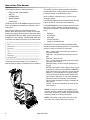


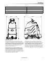

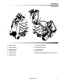
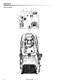


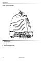

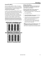
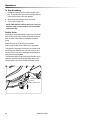
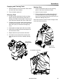

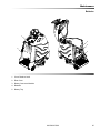

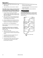

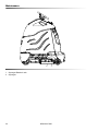

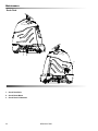
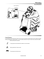
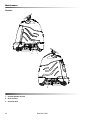


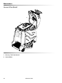

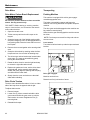
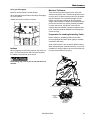
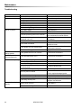
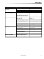

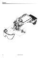

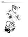

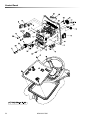
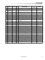
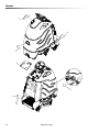
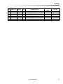
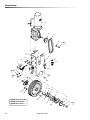
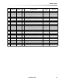

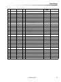
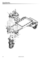
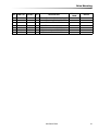
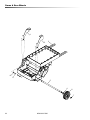
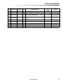
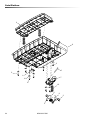

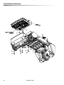
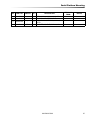

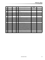

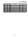
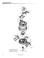
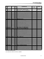
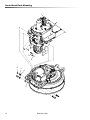
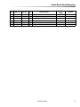
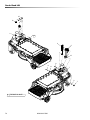
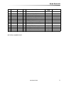
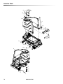
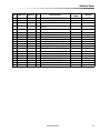


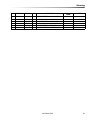
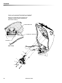

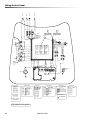

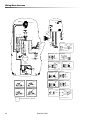

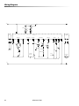

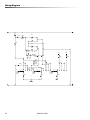
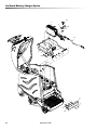

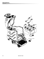

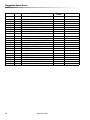


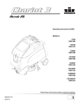
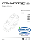
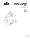
![取扱説明書 [F-04F] - ドコモビジネスオンライン](http://vs1.manualzilla.com/store/data/006720352_2-b3b968d491970b2f02e65c8be42fcc1d-150x150.png)