1
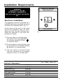
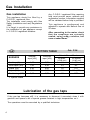
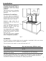
Gas Hob
Model:
C 761 G
GB
Instruction Manual
Thank you for buying your new CAPLE Gas Hob. To ensure that you get the best
results from your new CAPLE Gas Hob, we strongly suggest that you read this
instruction manual thoroughly before use. This manual contains installation advice,
usage instructions and a cleaning guide, as well as other important facts about your
CAPLE Gas Hob. If treated with care, your CAPLE Gas Hob should give you years
of trouble-free cooking.
Contents
Installation Requirements................ ........................................................................3
Gas Installation ................ ......................................................................................4
Installation ...............................................................................................................5
How To Use Your Gas Hob ............................ ......................................................8
Cleaning and Maintenance ............................ ......................................................11
Your Guarantee ..................... ...............................................................................12
For Spare Parts, Technical Advice
or Product Service call the
CAPLE HELPLINE on 0870 241 1142
(Answerphone outside office hours)
The
2
CE marking confirms that the appliance conforms to the following EU directives:
safety requirements of the “Gas” Directive 90/396/EEC;
safety requirements of EEC Directive “Low voltage” 73/23;
protection requirements of EEC Directive “EMC” 89/336;
requirements of EEC Directive 93/68.
Installation Requirements
DOUBLE POLE SWITCHED
FUSED SPUR OUTLET
WARNING!
ELECTRICITY CAN BE
EXTREMELY DANGEROUS.
THIS APPLIANCE MUST BE EARTHED.
Electrical Installation
FUSE
ON
This appliance must be connected by a
qualified electrician using fixed wiring via
a double pole isolating switch (fig. 1).
As the colours of the wires in the mains
lead for the appliance, may not correspond with the coloured markings identifying the terminals in your spur box,
proceed as follows:
USE A 3 AMP FUSE
Fig. 1
1) The wire which is coloured green
and yellow must be connected to
the terminal marked E (Earth)
or coloured Green.
2) The wire which is coloured blue must
be connected to the terminal marked
N (Neutral), or coloured Black.
3) The wire which is coloured brown
must be connected to the terminal
marked L (Live), or coloured Red.
Technical Information
Total absorbed power
Double-ring burner
Rapid burner (1)
Rapid burner (2)
Semi rapid burner
Auxiliary burner
Voltage
Cat.
I 2H - Class 3
11.25 kW
3.20 kW
3.05 kW
2.40 kW
1.60 kW
1.00 kW
230 V Single phase
3
Gas Installation
Gas installation
This appliance should be fitted by a
C.O.R.G.I. registered fitter.
The installation must comply with Gas
Safety (installation and use) Regulations
1994.
It is illegal to provide any assistance in
the installation of gas appliance except
to C.O.R.G.I registered installers.
GB
Any C.O.R.G.I registered fitter requiring
help must provide name, address and
registration number. Information supplied
will be validated before help is provided.
This appliance is predisposed and
adjusted to operate with Natural Gas at
20 mbar.
After connecting to the mains, check
that the couplings are correctly
sealed, using soapy solution, but
never a naked flame.
INJECTORS TABLE
BURNERS
Nominal
input [kW]
Reduced
input [kW]
Auxiliary (A)
1,00
0,32
Cat:
I 2H
Natural Gas - 20 mbar
By-pass
Ø injector
[1/100 mm]
40
[1/100 mm]
65*
Semi-rapid (SR)
1,60
0,39
43
85*
Rapid (R2)
2,40
0,58
55
110*
Rapid (R1)
3,05
0,67
60
115 (.15*)
Double-ring (DR)
3,20
0,77
62
125*
* = Injector brand
Lubrication of the gas taps
If the gas tap becomes stiff, it is necessary to dismount it accurately clean it with
gasoline and spread a bit of special grease resistant to high temperatures on it.
The operations must be executed by a qualified technician.
4
Installation
The hob must be installed by a
qualified technician and in
compliance with local safety
standard.
Take care not to lose or mishandle
any parts when unpacking the
appliance.
cabinet only
(without cooker hood)
Positioning the appliance
900 mm
450 mm
750 mm
COOKER HOOD
The hob must be installed a
minimum of 50 mm from the back
wall and 150 mm from any vertical
surface either side of the hob.
Adjacent units must be a
minimum of 450 mm above the
worksurface.
If you are installing a cooker hood
above the hob there must be a
minimum height of 750 mm
between the appliance.
If a cooker hood is not installed,
there must be a minimum height
of 900 mm between cabinets
above the hob.
This hob must not be installed
above refrigeration products.
Fig. 2
Ventilation
All rooms require a window which can be opened or equivalent, while some rooms
require a permanent vent in addition to a window.
This unit must not be used in a room with less than 5 m3.
Room Volume
5 m3
5 m3 to 10 m3
Greater than 11 m3
A room 5 m3 to 10 m3 with a door
opening to the outside
Air vent necessary (effective area)
100 cm2
50 cm2
No air vent necessary
No permanent air vent necessary
The above requirements allow use of a gas oven and grill but if there are other fuel
burning appliances in the same room BS5440 part 2: 1989 (ventilation) should be
consulted to determine the necessary air venting requirements.
5
Installation
1. The hob requires a space in the kitchen work surface as shown in fig 3.
Fig. 3
NOTE: A partition between the base of the hob and the cupboard below should be
fitted 100 mm below the worktop if the cupboard is to be used for storage.
Never place perishable foods in the cupboard below the hob.
2. Apply the adhesive seal around the edge of the hob, making sure that the ends do
not overlap or leave a space (fig. 4).
3. Attach the hob to the worktop using the brackets supplied as indicated in figure 5.
4. Tighten carefully.
5. Using a sharp tool, trim any excess gasket which protrudes from the edge of the
hob.
6. Assemble the three piece burners. Take care to properly locate the assembled
burner on the burner base (fig. 6).
6
C
;;;
A
Fig. 4
40 mm max.
B
20 mm min.
;;;;;;;;;
;;;;;;;;;
Adhesive
side
Fig. 5
Fig. 6
7
How to use your gas hob
4
3
15
5
14
13
12
11
10
1
2
Fig. 7
COOKING HOB
CONTROLS DESCRIPTION
1.
2.
3.
4.
5.
10. Electric lighter button
8
Auxiliary burner (A) - 1,00 kW
Rapid burner (R1) - 3,05 kW
Semirapid burner (SR) - 1,60 kW
Rapid burner (R2) - 2,40 kW
Double-ring burner 3,20 kW
11.
12.
13.
14.
15.
Burner
Burner
Burner
Burner
Burner
control
control
control
control
control
knob
knob
knob
knob
knob
1
2
5
3
4
(A)
(R1)
(DR)
(SR)
(R2)
Use of the burners
The arrival of the gas at the burner is controlled by a knob (fig. 8) which operates the
safety closing tap.
When the mark on the knob coincides with the symbols on the panel at the side, we
will have:
- symbol
●
tap off (burner off)
- symbol:
full flow (burner at maximum)
- symbol:
slow (burner at minimum).
To open the tap which allows the gas to reach the burner push the knob and turn it
to the left.
To close it, turn the knob to the right until the safety device releases.
The maximum flow is used for boiling, while the slow flow is used for simmering food
or keeping it on the boil.
All the operating positions must be chosen between the maximum and minimum
positions, never between the maximum and off positions.
Lighting the burners
Turn the knob to full flow and push the button with the
burner lights, then adjust the flame.
Fig. 8
★
Fig. 9
symbol (fig. 9) until the
9
How to use your gas hob
Cooking hints
The burners are different sizes, and can
be used in different ways; the largest for
boiling, to seal meat or foods that are
cooked quickly and the smallest for
stews and sauces.
Always ensure that you use the correct
size of saucepan.
For fast boiling, make sure that the
flame just reaches the edge of the pan.
Flames going up the side of the pan
means wasted heat and the contents
of the pan will take longer to boil.
Fig. 10
Warning:
During cooking the hob becomes
very hot, especially around the
cooking areas.
Keep young children away.
Cleaning and Maintenance
Advice for the user
• When the appliance is not being used, switch off the gas inlet tap.
Check the state of the connection hose to the bottle or to the gas distribution duct
occasionally; it must be in perfect condition and must be replaced if there are any
defects or depending on the date of use (case of a connection where the hose can
be inspected).
• Regular lubrication of the taps must be performed only by qualified staff. If there
are operating problems, contact the After-Sales Service Centre.
General advice
• Before you begin cleaning, you must ensure that the appliance is switched
off.
• It is advisable to clean when the appliance is cold and especially when cleaning
the enamelled parts.
• Avoid leaving alkaline or acidic substances (lemon juice, vinegar, etc.) on the
surfaces.
• Avoid using cleaning products with a chlorine or acidic base.
• Do not use a steam cleaner because the moisture can get into the appliance thus
make it unsafe.
10
Enamelled parts
All the enamelled parts must only be cleaned with a sponge and soap or other nonabrasive products. Preferably clean with a cloth.
Stainless steel
Clean with a suitable product. Always dry carefully.
Black burners (“oxi-black” coating)
They can be removed and washed only with soapy water.
Detergents can be used but must not be abrasive or corrosive.
Do not use abrasive sponges or pads.
Do not put in dishwasher.
After each cleaning, make sure that the burner-caps, as well as the burners, have been
well wiped off and CORRECTLY POSITIONED.
It is essential to check the correct position of the burner-caps as the least displacement
from the housing may cause serious problems.
For appliances with electric lighting, check that the electrode is always clean, to allow
regular production of sparks.
Troubleshooting
If you acquire a problem with your hob, check the following points before calling an
engineer.
1.
2.
3.
4.
The power is switched on.
The controls are switched on.
Both the fuse and the mains fuse are intact.
The gas supply is connected to the appliance.
If you are in any doubt about carrying out these checks, call the CAPLE Helpline on
0870 241 1142.
11
CAPLE “Built-in” Service
Should you require service at any time,
please contact the Caple Helpline on
0870 241 1142.
Caple have a nationwide service network of engineers who will respond
quickly to your call.
Always replace spare parts with genuine Caple spares. These are available
from authorised Caple Service
Centres or by mail order from our
National Service Stores, simply telephone 0870 241 1142.
When ordering parts always quote the
model number and serial number of
your appliance.
YOUR GUARANTEE
CAPLE guarantees all parts of this product for one year from the date of purchase. During that time, should it become necessary CAPLE engineers will
replace or repair all defective parts free of charge, except for parts subject to
fair wear and tear, such as lightbulbs.
Parts and the engineers labour costs are chargeable after the first 12 months.
To qualify for benefits under the guarantee, you must be able to provide proof
of date of purchase and the appliance must have been supplied, installed and
used for domestic purposes only in accordance with CAPLE instructions.
Consequential losses and accidental damage to the product are not covered
by the guarantee.
This guarantee does not affect your statutory or common law rights.
ß2
CAPLE cannot be responsible for the results of using this appliance for any
other purposes other than those described in these instructions.
Cod. 1101809