1
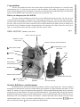
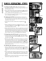
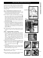
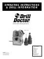
OPERATING INSTRUCTIONS
& DRILL INFORMATION
MODEL 750SP
CONTENTS
US Patents
D385567, & 4,471,581
5,735,732 & 5,400,546
other Patents Pending
Warranty
Congratulations
Quick Steps
Instructions
Maintenance
Quick Facts
Replacement Parts
Troubleshooting
1
2
3
4
7
8
9
10
US DEPARTMENT OF LABOR
Form Approved Occupational Safety and Health
Administration
OMB No. 44-R1367
MATERIAL SAFETY DATA SHEET
Required under USDL Safety and Health Regulations for Ship Repairing, Shipbuilding and Shipbreaking
(29 CFR 1915, 1916, 1917)
SECTION I
MANUFACTURES NAME:Professional Tool Manufacturing LLC
EMERGENCY PHONE NO: (541) 552-1301
ADDRESS: 210 East Hersey Street, Ashland, Oregon 97520
CHEMICAL NAME & SYNONYMS: Diazon-Electroplated Diamond/CBN Products, Diamond (uncoated),
Man-Made * Diamond, RVG, MBG, MBS Product Families, Standard Series and 300 Series Diamond
Micron Powder
TRADE NAME & SYNONYMS: Electroplated CBN Wheels, Electroplated Diamond Wheels
CHEMICAL FAMILY: Abrasive/Any Grade
FORMULA: N/A
SECTION II - COMPOSITION
CHEMICAL NAME:
Nickel
Industrial Diamond
REGULATED:*
Yes
No
CAS#:
7440-02-0
7882-40-3
AGIH / TLV:
1.0 mg/m3
10.0 mg/m3 (PNOC)
CARCINOGEN:
Yes
No
*Materials are regulated by OSHA 29 CFR 1910,1200, Hazard Communication Standard.
SECTION III - PHYSICAL AND CHEMICAL DATA
BOILING POINT (F)
n/a
MELTING POINT
n/a
SPECIFIC GRAVITY
n/a
VAPOR PRESSURE
n/a
VAPOR DENSITY
n/a
EVAPORATION RATE
n/a
SOLUBILITY IN WATER n/a
SOLUBILITY IN ALCOHOL
n/a
SOLUBILITY IN OTHER SOLVENT
n/a
PERCENT VOLATILE BY VOLUME (%)
n/a
APPEARANCE AND ODOR: Solid, Clear, White To Yellow To Dark Crystals Silver Color.
SECTION IV - FIRE AND EXPLOSION HAZARD DATA
FLASH POINT
n/a
(METHOD USED)
FLAMMABLE LIMITS
LEL
UEL
EXTINGUISHING MEDIA:
n/a
SPECIAL FIRE FIGHTING PROCEDURES:
n/a
UNUSUAL FIRE AND EXPLOSION HAZARDS:
n/a
SECTION V - HEALTH, FIRST AID AND MEDICAL DATA
PRIMARY ROUTE(S) OF ENTRY:
Inhalation, Ingestion, Skin, Eye(s)
EFFECTS OF OVEREXPOSURE:
INHALATION: Difficulty in breathing (Dust from wheel use).
INGESTION: If dust, symptoms are variable.
SKIN: Irritation (especially if sensitive to Ni).
EYE(S): Irritation (from Ni or diamond particle).
FIRST AID AND MEDICAL INFORMATION:
INHALATION: Move to fresh air. Give oxygen if necessary.
INGESTION: Obtain medical attention.
SKIN: Wash thoroughly with water. Obtain medical help if necessary.
EYE(S): Flush thoroughly with water. Obtain medical assistance.
OTHER POTENTIAL HEALTH RISKS:
Nickel (Ni) is listed as a carcinogen. Avoid long exposure. Consult medical personnel for first aid
and medical information.
SECTION VI - CORROSIVITY AND REACTIVITY DATA
STABILITY:
Unstable ( )
Stable (x)
POLYMERIZATION:
May occur ( )
Will not occur (x)
INCOMPATIBILITY (Materials to avoid)
n/a
HAZARDOUS COMPOSITIONS PRODUCTS:
n/a
CONDITIONS TO BE AVOIDED: Contact with strong acids/caustics; enclosed areas.
SECTION VII - SPILL, LEAK AND DISPOSAL PROCEDURES
STEPS TO BE TAKEN IN CASE MATERIAL IS RELEASED OR SPILLED:
Normal clean up procedure
WASTE DISPOSAL METHOD: Waste will contain nickel. Dispose in accordance with all applicable
federal, state, and local regulations.
SECTION VIII - PERSONAL PROTECTION INFORMATION
RESPIRATORY PROTECTION:
Respiratory protection as needed see OSHA 29 CFR 1910.134
VENTILATION:
LOCAL EXHAUST: strongly preferred
MECHANICAL (GENERAL): Use only if adequate to maintain below TLV’s.
PROTECTIVE GLOVES: As desired by user.
EYE PROTECTION: Recommended see OSHA 29 CFR 11910.215
OTHER PROTECTIVE EQUIPMENT: Use standard precautions for grinding operations.
SECTION IX - STORAGE AND HANDLING PROCEDURES
NORMAL STORAGE AND HANDLING: Store in clean, dry area, away from chemicals.
NORMAL USE: Use adequate ventilation (see Section VIII)
PAGE (1)
1
FORM OSHA-20
IMPORTANT SAFETY INSTRUCTIONS
REMEMBER, FOR YOUR OWN SAFETY, READ
INSTRUCTION MANUAL BEFORE OPERATING TOOL. Wear
Eye Protection. Never touch internal parts of the sharpener when
the sharpener is on. The rotating diamond grinding wheel can cause
injury. Use caution when replacing the grinding wheel. Follow
instructions entitled “Replacing The Grinding Wheel” in this
Instruction Manual. Regularly empty accumulated grinding dust.
Follow instructions entitled “Drill Doctor Maintenance” in this
Instruction Manual.
WARNING : WHEN USING ELECTRIC TOOLS, BASIC SAFETY
PRECAUTIONS INCLUDING THE FOLLOWING SHOULD
ALWAYS BE FOLLOWED TO PREVENT THE RISK OF FIRE,
ELECTRIC SHOCK AND PERSONAL INJURY.
1. KEEP GUARDS IN PLACE
2. REMOVE WRENCHES. Form a habit of checking to see that the
wrench is removed from tool before turning on.
3. KEEP WORK AREA CLEAN. Cluttered areas and benches invite
accidents.
4. DO NOT USE IN DANGEROUS ENVIRONMENT Don’t use
power tools in damp or wet locations, avoid exposure to rain.
5. STORE EQUIPMENT in a safe place when not in use.
6. DON’T FORCE TOOL. It will do the job better and safer at the rate
for which it was designed.
7. USE RIGHT TOOL. Don’t force tool or attachment to do a job it was
not designed for.
8. ALWAYS USE SAFETY GLASSES. Also use face or dust mask if
cutting operation is dusty. Everyday eyeglasses only have impact
resistance lenses, they are NOT safety glasses.
9. MAINTAIN TOOL WITH CARE. Keep tools sharp and clean for best
and safest performance.
10. DISCONNECT TOOLS from the power supply before
servicing,when cleaning accessories.
11. AVOID ACCIDENTAL STARTING. Make sure switch is in “OFF “
position before plugging in.
12. USE RECOMMENDED ACCESSORIES.
13. CHECK FOR DAMAGED PARTS. Before further use of the tool, a
guard or other part that is damaged should be carefully checked to
assure that it will operate properly and perform its intended function.
Check for alignment of moving parts, binding of moving parts,breakage of parts, mounting and any other conditions that may affect its
operation. A guard or other part that is damaged should be properly
repaired or replaced.
14. NEVER LEAVE TOOL RUNNING UNATTENDED.
15. USE PROPER EXTENSION CORD. Make sure extension cord is in
good condition. When using an extension cord be sure to use one
heavy enough to carry the current the Drill Doctor® will draw. An
undersized cord will cause a drop in line voltage, resulting in a loss of
power and/or overheating. Maximum cord length (5O ft), minimum
gauge (16). The smaller the gauge the heavier the cord.
DRILL DOCTOR ® WARRANTY
Professional Tool Manufacturing LLC warranties your Drill
Doctor® to be free of defects due to workmanship and
design for 1 year following the first day of in service use.
For warranty service see warranty card instructions or contact your authorized Drill Doctor® dealer.
You have just purchased the finest, most accurate and best engineered drill bit sharpener ever created for home
and professional use. It is likely that your experience with this sharpener will be unlike any sharpener you have used
before. We hope that in the next several minutes you will discover how Professional Tool Manufacturing LLC and the Drill
Doctor® help to SIMPLY improve the quality of your life (and your drill bits’ too!).
Before you sharpen your first drill bit
Take a few minutes to familiarize yourself with your new Drill Doctor® and its basic parts. We will refer to all
of the parts and features (Figure 1) during the course of this manual and in the video. There are some features and characteristics unique to the Drill Doctor® which are explained and illustrated within the instruction section of this manual and
the video. Don’t worry, the time it takes to watch the video or read this manual will be made up when you sharpen your
first drill bits. Keep in mind that learning to sharpen drill bits is like learning to ride a bike: it takes a few tries to get it
right, so you should expect that it may take a couple of drill bits to get the “point”.
DRILL DOCTOR® (MODEL 750SP Shown)
Fig. 1
CONGRATULATIONS
Congratulations
POINT ANGLE GAUGES
WHEEL COVER
PP01434PF
ANGLE CHANGE LOOP HANDLE
3 SHARPENING TUBE
PP01426PA
4 SPLIT POINT TUBE
2 PADDLE
FLAT
MASONRY
CAM
SPLIT POINT
STANDARD POINT
POWER CORD
3/4” CHUCK
SA01750PA
1/2” CHUCK
SA01500PA
SPRING STEEL PAWLS
1 ALIGNMENT TUBE
PP01455PF
ALIGNMENT TUBE
HANDLE
CHUCK KNOBS
ON/OFF SWITCH
About the Drill Doctor® and this manual
The Drill Doctor® is most efficient when used to resharpen a drill bit’s original point angle. It has been designed
and engineered to sharpen three of the most common drill bit types: standard 118°, high-performance split point 135°, and
carbide 135° masonry (see page 9 for illustrations and applications). With its standard diamond grinding wheel it will sharpen high-speed steel, cobalt, parabolic, TiN coated, and solid carbide drill bits. The troubleshooting section of this manual is
designed to anticipate many common questions and applications. To keep your Drill Doctor® and your drill bits in top condition please refer to the maintenance section of this manual. Available replacement wheels and parts are shown in the
exploded diagram (page 8). They are available from Drill Doctor® or your dealer. Please note that the
symbols
refer to the three tubes and the
refers to the paddle on the Drill Doctor®.
2
QUICK STEPS
QUICK OPERATING STEPS
A-1
Models 500SP & 750SP
A. Setting for split point style
(full instructions page 4)
1. Determine the point angle of your drill by placing the drill point in the
point angle gauges. See A-1
A-2
2. Insert a chuck (without drill) into the sharpening tube
and pull the
loop handle out. Move point angle indicator to the setting needed (118°
or 135°). Make sure the loop seats properly. See A-2
3. Pull the alignment tube
handle slightly away from the housing and
move to the (Split Point) setting. See A-3
B. Aligning the drill bit
PAWLS
(full instructions page 4 and figure 9)
1. Insert the drill loosely into the chuck. Tighten the chuck knob clockwise, then loosen it so the metal chuck jaws are just loose enough for
the drill bit to slide in and out.
2. Align the flat on the chuck with the flat in the alignment tube
See B-1
A-3
.
3. Push the paddle
to open the blue spring steel pawls. See A-3. Push
chuck and drill assembly into alignment
tube so that the flat on the
chuck is entirely hidden. See B-2
B-1
B-2
4. Push the drill in to the drill stop. Release the paddle and rotate the drill
by the shank until the pawls grip inside the drill flutes. Keep the drill bit
pushed to the drill stop and turn the chuck knob clockwise to tighten the
jaws onto the drill bit. Push the paddle back and remove the chucked
drill (see Figures 8 and 24 for correct alignment and terminology).
C. Sharpening the drill bit point
FLATS
(full instructions page 5)
1. Turn the switch below the sharpening tube on. Position the sharpener so that you are looking at it from the perspective shown in C-1. Insert
the chuck in the tube .
C-1
2. Rotate the chuck clockwise, in half rotation increments, 12 to 20 times
(on a medium size drill bit 1/4” to 3/8” ) in the sharpening tube . It
is important to keep consistent pressure going INTO the tube . Let the
cam dictate the natural in and out sharpening motion. The sharpening
will occur in the low part of the chuck cam. Do not push the chuck
down to the base. See C-2
C-2
D. Splitting the drill point
(full instructions page 6)
1. Move the chucked drill to the point splitting tube
and again
match the flats on the chuck with the flats in the tube . Insert the
chucked drill until the flats are touching and the chuck does not
rotate.
2. Slowly pull the chuck forward giving the drill bit one or two short
”pecks” on the wheel. Repeat untill the split is to the middle of the
drill point. To avoid over-splitting inspect the drill point periodicaly.
See D-1
3. Pull the chuck out of the point split tube just far enough to rotate the
chuck 180°. Repeat steps 1 and 2 above.
3
D-1
INSTRUCTIONS
DRILL DOCTOR® INSTRUCTION MANUAL
Fig. 2
If possible, the first couple of drill bits you sharpen should be
about 3/8" in diameter, or large enough to see how the point looks.
Study Figure 1 on page 2 and the Figures 26 and 27 on page 8.
Various Drill Doctor® and drill bit parts will be referenced in the
following sections.
Angle Gauges
Step 1: Drill Identification and Sharpener Set Up
A. Place the drill in the point angle gauge (see Figure 2). Note
how the chisel edge and cutting lip fits in the gauge. A correct
fit is along the entire point, an incorrect fit is not.
B. The “correct fit” gauge is what point angle you should set.
Insert a chuck, without a drill in it, into the sharpening tube .
Pull the “loop” handle away from the housing with your index
finger and thumb, then using the chuck as a lever, move up or
down to set the angle indicator (see Figure 3). Make sure the
angle indicator seats in the notches on the left and right sides of
the sharpening tube .
C. Pull the alignment tube
handle slightly away from the housing and move the alignment tube to the appropriate drill bit profile (see Figure 4). Make sure to seat the handle into the corresponding notch in the housing behind the handle. The alignment tube
is now set and ready to “set” the drill bit in the
alignment procedure.
Fig. 3
Loop Handle
Note: This procedure can be used to increase or decrease “relief”
on a drill bit. See pages 5 and 10 for full discussion and applications.
STEP 2: Aligning Drill Bit For Sharpening
A. Turn the chuck knob, counter-clockwise (CCW) to open the
chuck jaws, until you can insert the drill bit into the chuck (see
Figure 5). With the drill bit in the chuck, turn the chuck knob
clockwise (CW). This will close the chuck jaws onto the
“flutes”. Turn the chuck knob until it stops then loosen the
chuck jaws slightly by turning the chuck knob CCW. At this
stage the drill bit should have a “slip-fit” and will slide in or out
and rotate freely within the chuck.
B. Align the flats on the chuck with the flats in the alignment tube
. Slide the chuck into the alignment tube all the way until
it stops. At this point the flat on the chuck nose should be
entirely hidden inside the alignment tube
(see Figure 6).
C. Push the paddle
back all the way to the housing. Hold the
paddle then grasp the shank of the drill bit and push it into the
chuck to the drill stop (see Figures 7 & 8).
Note: At this stage, if the drill bit is too short to push, see
“Sharpening Short Drill Bits” on page 6.
Fig. 4
Masonry
Split Point
Standard
Fig .5
Fig. 6
F l at
F l at
Fig. 7
Fig. 8
Drill Stop
D. Release the paddle, but continue pushing the drill bit in against
the stop. The two pawls will close onto the drill bit.
4
INSTRUCTIONS
STEP 2: Aligning Drill Bit For Sharpening (continued)
E. Look into the opening in front of the paddle. Note the location of the
two spring steel pawls. Rotate the drill bit until the pawls slip in and
grab the flutes at the narrowest point. Continue to push the drill bit
against the drill stop (see Figure 9).
F. With the drill point against the drill stop and the pawls in their correct
position, tighten the chuck by turning the chuck knob CW with the
other hand. Push the paddle
back again to release the drill bit.
Remove the chuck and drill assembly from alignment tube . Snug
the chuck knob CW using both hands to secure the drill bit in the
chuck.
Fig. 9
Correct
Wrong
Fig. 10
STEP 3: Sharpening The Drill Point
A. Turn the Drill Doctor® switch on.
B. Place the chuck into the sharpening tube . Align the high part of the
cam with the top cam follower and push it in all the way. This will prevent the drill bit from crashing into the wheel.
C. Lightly pushing INTO the sharpening tube (see Figures 10&11).
Rotate the chuck CW in half rotation increments, similar to the motion
used to turn a doorknob. Rotate the chuck 12 to 20 times on a medium
size drill bit 1/4” to 3/8”. It will take more rotations for larger drill bits
and as few as 2 rotations on small drill bits. The sharpening tube will
move in and out during this process. Let the cams dictate the natural in and out sharpening motion. The sharpening will occur in the “valley” of the cam. Maintain consistent contact with the cams and cam
followers.
NOTE: The sharpening tube is moving in and out due to the secondary or
feed cam on the chuck riding against the top cam follower. The initial
grinding occurs when the “valley” of the feed cam rides against the top
cam follower (see Figure 12). If at the start of the grind, the feed cam
on the chuck is NOT touching the top cam follower, then it is the result
of the drill point being against the wheel and preventing the feed cam
from touching the follower. As you continue to grind and remove material, the feed cam will begin touching the cam follower and start to produce the correct relief angle behind the drill bit’s cutting lips.
Additionally its important to keep the bottom cam follower in contact
with the high lobes on the feed cam. These cams work together in producing the radial grind and proper relief on the drill point.
Push INTO tube
Do not push down
Fig. 11
Fig. 12
Follower
Feed Cam
About Relief Angle Settings
If after aligning your bit and sharpening it, the relief needs to be
increased or decreased, then the following procedure is required.
A. Rotate the alignment tube from the point split setting to the standard
setting to increase the relief. The further counterclockwise the tube is
turned the more relief the drill will have.
B. To decrease relief set the timing tube to the masonry location. The further clockwise the tube is turned the less relief the drill will have.
C. Reference Figure 13 and #2 in the troubleshooting section on page 10
for more information on negative relief.
5
Valley
Follower
Fig. 13
Correct Relief
Negative Relief
INSTRUCTIONS
STEP 4: Splitting The Drill Point
Fig. 14
You can split either a 118° or 135° drill point. Refer to Figure 31 on page
10 for a drawing and definition of a properly split drill bit point.
A. After sharpening the drill point, do not remove the drill bit from the
chuck. Align the flats on the chuck with flats in the splitting tube
and
insert to the point where the flats are touching (See Figure 14).
B. Slowly pull the chuck forward giving the drill bit one or two short ”pecks”
on the wheel (See Figure 15). Pull the chuck out and inspect the point.
Depending on the size of the drill bit, it may be necessary to repeat steps
Fig. 15
A and B until the drill point is split to the middle (See Figure 31).
C. Pull the chuck out of the splitting tube
far enough to rotate it 180°.
Repeat steps A & B to split the other side.
Flats
NOTE: The rule of thumb is “it’s better to grind off not enough rather than too
much”. If the drill point is over-split, try re-sharpening in the sharpening tube
to reduce the over-split. If this doesn’t work repeat steps #2 – #4.
Sharpening Short or Small Diameter Drill Bits
A. Complete Step 2A on page 4. When completed, remove the drill bit from
the chuck.
Fig. 16
B. Push the paddle back, and insert the individual drill bit into the alignment
tube
all the way to the drill stop. Release the paddle and turn the drill bit
until it is secured by the pawls and pointing straight out
(see Figure 16).
C. Continue to hold the drill bit with one hand and carefully slide the chuck onto
the drill bit with the other (See Figure 17). Align the flats on the chuck with
the flats in the alignment tube
and push the chuck all the way in until the
flats on the chuck are entirely hidden. Tighten the chuck jaws onto the drill
bit with the chuck knob. Push the paddle
back and remove the chucked Fig. 17
drill bit.
D. Look in to the back of the chucked drill. The chuck jaws around the drill bit
should be in line. If not, turn the chuck knob counter clockwise to straighten (See Figure 18).
E. Sharpen in tube .
Fig. 18
Chuck jaws are inline
NOTE: Too many rotations on small diameter bits will result in a
negative rake angle. Example: 3/8” rotate (16-20) 180 degree
turns, 1/8” rotate (4-6) and 3/32” (2-4).
Sharpening Masonry Drill Bits
A. Set the point angle indicator to 135° (see Figure 2 on page 4).
B. Set the alignment tube
pointer to the masonry position.
(See Figure 4 on page 4)
C. Complete Steps 2A and 2B on page 4.
Fig. 19
NOTE: When aligning the masonry drill bit , the pawls are not used in the alignment Fig. 20
process. Push the paddle back to the housing and insert the drill bit to the stop,
then release the paddle. Disregard the position of the pawls.
2 o’clock
D. Grasp the shank end of the drill bit and rotate it so that the right cutting lip is high in
a 2 o’clock position (See Figure 19 and 20). Tighten the chuck knob. Push the paddle back and remove the chuck from the tube.
E. Sharpen in the sharpening tube .
NOTE: The masonry drill bit may also require fewer rotations than
similar diameter standard drill bits.
6
MAINTENANCE
DRILL DOCTOR® MAINTENANCE
Fig. 21
After sharpening many drill bits, the drill bit grinding dust will accumulate in the
grinding compartment. Grinding particles will promote wear in the three tubes and
chucks, so cleaning on a consistent basis can add life to your machine. Before any
maintenance or cleaning is performed, be sure to unplug your Drill Doctor®.
Chuck Grooves
Cleaning The Drill Doctor ®
Unplug the Drill Doctor®. With a dry cloth wipe the inside and outside of the three
tubes to remove any grinding dust that may have accumulated. A standard 1 ⁄” vacuum hose works equally well. To empty the drill bit grinding dust remove the black
cover from the top of the machine.
Fig. 22
Removing The Wheel Cover
Unplug the Drill Doctor®. Using the narrow end of the wrench provided (or a flat head
screwdriver) insert into the slot on the rear of the machine and use a twisting motion
to pry the cover off. Shake accumulated drill bit grinding dust into a disposable container. Remove dust particles around wheel with a small dry brush. Dispose of container and drill bit dust in a safe and environmentally approved manner.
Cleaning The Chucks
With pressurized air, blow the chuck out from the chuck knob end. For further cleaning, disassemble the chuck by simply unscrewing the closing knob on the chuck and
removing the chuck body. Clean the inside of the chuck with a dry paint brush. (Do
not remove the springs and jaws from the holder!) Once the inside of the chuck
has been cleaned - slide the chuck body onto the jaws - sighting down the nose make
sure that the jaws go into the grooves inside the chuck body. Rotate the closing
knob clockwise to reassemble the chuck, checking that all of the jaws are in their
respective grooves (see Figures 21 and 22).
Determining if a Wheel Change is Required
A wheel may need to be changed if:
1. Sharpened drill bits will burn or turn blue no matter how fast or slow you rotate the chuck.
2. Upon inspecting the wheel, by touching it, it feels like there is not any abrasive on
the lower portion.
3. When sharpening the drill bit, it takes too many rotations to sharpen.
The grinding wheel can be reversed to utilize the unused half. If the wheel has
already been reversed, it will need to be replaced. Contact the store or dealer where
you purchased the Drill Doctor® to purchase a replacement wheel
(Part #SA01326GA).
Reversing or Replacing The Diamond Grinding Wheel
Unplug the Drill Doctor®. Remove the wheel cover as described above. The wheel is
attached to the hub with two Phillips head screws and a wheel retainer. Use the wrench
provided by inserting it directly below the wheel onto flats located on the wheel hub.
Remove the screws, wheel retainer and the worn wheel using a twisting motion. Install
the new wheel, wheel retainer and the screws. Do not over tighten the mounting screws
(see Figures 23 and 28).
Cleaning or Replacing the #1 Alignment tube
Grasp the alignment tube handle and pull it forward slightly. This will disengage
the handle from the notches in the front of the housing. Rotate the handle counterclockwise until it is almost vertical. Once it is in that position, pull forward and it
will unlock from the front of the housing. Wipe the part off with a dry rag and vacuum the front alignment hole to remove any particles from the machine. Reinsert
the alignment tube in the opposite way that it was removed.
7
Fig. 23
Remove
Cover
Insert
Wrench
Remove Screws
Fig. 24
QUICK FACTS
Quick Facts About Drill Bits
Fig. 25
118°
118° STANDARD POINT: This drill bit point angle is considered a
standard general purpose geometry . It is used for drilling soft or
mild materials such as cold rolled steel, aluminum, and wood.
Typically the standard drill bit is made of High Speed Steel (HSS).
The tip of the drill bit can easily be split making it a High
Performance drill bit.
135° HIGH PERFORMANCE SPLIT-POINT: The flatter point
angle of this drill is designed for harder, tougher materials such as
tempered steels, hard alloys or hard cast metals. Metal types in
split-point drill bits vary (see below). Due to the thicker web and
flat point angle this drill point works best when its split-point is
maintained.
135°
MASONRY DRILL BITS: This point angle is typically 130° to 135°.
New masonry drill bits are generally sharpened with a facet or flat
style grind. Masonry drilling is typically not a precision operation.
The masonry drill bits resharpened with the Drill Doctor® will
look different due to a radial (curved) grind. However, this style of
grind will perform as well as the original drill point.
SPLIT POINTS: Split point drill bits tend not to walk around on the
material before they begin to cut. This feature is described as self
centering. The need to center punch is effectively eliminated. A
standard drill bit chisel point has to wear an area in the middle of
the hole prior to the cutting lips removing material. Due to its
additional cutting lips along the chisel edge a split point will begin
cutting immediately. Up to 70% less thrust (when compared to a
non-split or conventional point) is required to drill a hole with a
split point. You can split either the 118° or the 135° degree points
with Drill Doctor®.
Masonry
Fig. 26
ANATOMY OF A DRILL BIT
CARBIDE DRILL BITS: This point angle is typically 130º to 135º.
Carbide is harder and more brittle than high speed steel and cobalt.
This type of drill is used for drilling tempered steels, alloys, glass,
Etc. Carbide drill bits can be sharpened with your Drill Doctor®.
PARABOLIC AND COBALT DRILL BITS: Have a thicker web
than regular drill bits. Parabolic drill bits are designed to drill deep
holes. Cobalt drill bits are Titanium Nitride (TiN) coated. TiN is
applied to increase a drill bit’s cutting efficiency. Most of these
drill bits can be sharpened with your Drill Doctor®.
LIP RELIEF ANGLE: The relief on a drill bit is the downward angle
between the cutting lips (leading edge) and the heel (trailing edge)
on the drill point. If the drill bit cutting lips are not higher than the
heel, then the drill bit will not cut into the material. This is often
referred to as negative relief (see page 5 &10). The Drill Doctor®
is designed to grind a standard factory relief on your drill bits.
Fig. 27
CHISEL EDGE ANGLE: The chisel edge is the line across the point
of a drill bit. Note in Figure 27 the chisel edge angle is between
120º and 135º. Another way to look at a chisel edge is to imagine
the drill point as a clock face with the chisel angle pointing to an
approximate one o’clock position. Most drill bits are set to this
angle.
WEB: The web is the core thickness of a drill point. It is typically
around 10% of the drill bit diameter. As a drill bit is sharpened the
web thickness will increase. Splitting the point or thinning the web
on a drill bit will maintain drill bit performance (See Figure 26).
120° to 135°
Chisel Edge
Angle
Chisel Edge
Included Angle
of Point 118°
Cutting Lip
Heel
8
" - 3/ 4 "
3/3
9
MM
Hub Wrench
3/32" to 1/2" Chuck
part # PPO1460SF
# PPO1500PA
partpart
#SA01500PA
MM
1/
2
- 1 /2 "
2"
13 - 1
User Replacable Parts
2 .5 - 1 3
REPLACEMENT PARTS
Fig. 28
1/2" to 3/4" Chuck
part #SA01750PA
# PPO1750PA
part
Wheel Cover
1/2" Diamond
Grinding Wheel
part # PPO1434PF
part
part ##SA01326GA
PPO1325GF
Sharpening Tube
part
PPO1246PA
part##PPO1426PF
PR
EC
ISIO
N
DR
ILL
BIT
SH
AR
PE
NE
R
Alignment Tube
part # PPO1455PF
FRONT VIEW
Screws and
Mounting Bracket
DD750 Parts Bag
REAR VIEW
part # SAO1459PA
DRILL DOCTOR ® TIPS
move tube 1 slightly above the standard setting. Check
the alignment again and adjust accordingly.
Fig. 29
Slow and Fast Spiral / Helix Drill Bits, Raised
Margin Drill Bits & Negative Relief: Using the standard drill setting align the bit in the chuck. Visually
check the alignment of the bit before sharpening. Note
the position of the two chuck flats, (remember the flats
are what lock the chuck in the alignment & splitting
tubes). Draw an imaginary line from the middle of the
flat up through the drill bit. That line should end up on
the heel of the drill bit (see Figure 29). This check will
hold true on drill bits from 3/32” to 1/2”. If the line
does not fall on the heel, then the alignment tube must
be adjusted. If the line falls to the right of the heel,
move tube slightly below the standard setting. The
chisel edge will rotate clockwise if the alignment setting is moved too far. If the line falls left of the heel
9
Heel
Heel
Cutting Lip
Chuck Flat
Chisel Edge
Drill bit backing up into chuck during sharpening
procedure: Follow the chuck disassembly procedure on
page 7 of the ops manual. Using compressed air, a small
brush or rag, wipe between the white/black pusher (the
pusher is the piece holding the jaws and springs) and the
chuck knob. Rotate the knob to make sure all dust/grit is
removed. Reinstall chuck body to chuck knob; ensuring
the jaws are in the jaw grooves.
You can take less material off of a drill bit. The
sharpener will remove approximately .015” to .025”
depending upon the point angle that is sharpened. To
align the drill bit to remove less material, merely insert
a shim or feeler gauge between the drill bit point and
the metal stop where the drill bit normally touches during alignment.
TROUBLESHOOTING
1. I aligned the drill bit and sharpened it, but no material gets
removed. You may have allowed the paddle
to knock the
drill back into the chuck. Carefully realign the drill in the alignment tube
again. Make sure the drill is pushed all the way
against the drill stop (see Figure 8 on page 4).
2. I’m getting negative relief. Negative relief is present when the
heel of the flute is higher than the cutting lip on a drill. When this
happens the drill will not cut. To correct negative relief, set the
alignment tube to the non-split setting. Turning lever number 1
counter clockwise will increase relief. Realign the drill and
resharpen in the sharpening tube . Maintain consistent inward
pressure to the grinding wheel during the chuck rotation.
Fig. 30
Correct Relief
Negative Relief
5. What can I do about the flat spot between the lip and the
heel? The flat spots or chattering on a sharpened drill, are the
result of an incomplete or fast rotation of the chuck in the sharpening tube . To correct, apply firm, not excessive inward pressure and rotate the chuck smoothly while sharpening. Be sure to
complete the grind.
6. The chisel edge on my drill bit is flat. During the alignment
process the pawls were gripping “ON” the flutes of the drill bit.
Re-align the drill bit making sure that the pawls are located in the
narrowest section of the flutes.
7. After sharpening, the grind finish on my drill is rough.
Grind finish is initially rough when sharpened by a new diamond
wheel. Drill performance will not be noticeably affected however. The finish will improve as the diamond coating breaks down.
8. My small drills are grinding off center. After aligning the
small drill, look into the back of the chuck and notice if the jaws
are straight to each other. If the jaws are twisted in a spiral direction, grasp the closing knob and very carefully turn it counter
clockwise to straighten the jaws. This procedure will center the
drill in the chuck.
TROUBLESHOOTING & TIPS
Reverse the grinding wheel before you replace it.
The grinding wheel supplied with the Drill Doctor® is
designed to give you long and trouble-free service, on
average over 200 sharpenings. Eventually, you will
need to replace the wheel. However, before you replace
the wheel you can flip it over. Drill point burning and
an increase in drill bit sharpening time are indicators
that the wheel needs replacement. See page 7
9. My drill point was sharpened improperly. The most common cause of improper sharpening is not aligning the drill in the
chuck properly. Key causes are: 1. Drill point not pushed all the
way to the drill stop. 2. Chuck not pushed all the way into the
alignment tube. 3. Drill not aligned in the pawls correctly.
In order to correct these problems be sure the chuck is all the way
in the alignment tube
with the flats entirely hidden. The drill
point is against the drill stop and the pawls are located in the narrowest section of the drill flutes.
10. Why is my point split uneven? Figure 31 shows a drill point
that is under split and a drill point that is correctly split. To correct an uneven point split take more material off of the under split
flute. To do this, reinsert the chuck in the
splitting tube with
the under split flute on top. Repeat Step 2B (page 6) until split is
correct. A correct split point should look symmetrical. The two
parallel lines formed by the split should have a separation of .005
to .012 of an inch on the chisel angle.
Fig. 31
3. Why is the drill point off center? If the tip of the drill bit
appears to be sharpened off center, check the following items:
a. Make sure that there are no particles between the chuck jaws
and the drill bit, which could hold it off center. b. Note if the closing knob is closed firmly enough to hold the drill bit on center.
c. During the sharpening process be sure not to push unevenly during the rotations. If the point split appears off center see #10.
4. Why don’t my drills align like the “correct” diagram? There
may be a burr on the drill shank (remove burrs with a flat file).
Also, the drill may be too loose or too tight in chuck.
Correct
Incorrect
If this guide and the video do not answer your questions call
Professional Tool Manufacturing LLC customer service at
1-800-597-6170 or 1-541-552-1301.
Watch Professional Tool Manufacturing LLC
for new innovative products.
http://www.drilldr.com
10
Dear Customer,
We appreciate the confidence you have placed in
us by purchasing the Drill Doctor ® and we want
you to be as excited about this remarkable tool as
we are. It’s easy to use correctly, if you follow the
instructions. We have created this manual and
video in order to give you the information you
need to effectively master its operation and get the
satisfactory results you expect from Professional
Tool Manufacturing LLC.
MODEL 500SP
3/32” - 1/2” CHUCK
1/2” DIAMOND WHEEL
110V 60Hz 1.75 AMP MOTOR
MODEL 750SP
3/32” - 1/2” CHUCK
1/2” - 3/4” CHUCK
1/2” DIAMOND WHEEL
CHUCK STORAGE RACK
110V 60Hz 1.75 AMP MOTOR
P.O. Box 730
Ashland, OR USA 97520
Phone (541)552-1301 Fax (541) 552-1377
http://www.drilldr.com
Listed 39MJ
PP01481KF Rev.3