1
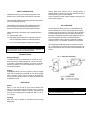
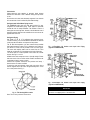
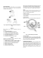
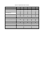
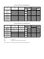
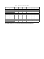
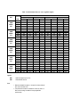
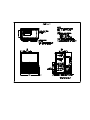
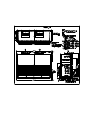
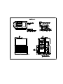
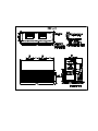
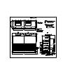
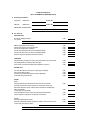
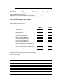
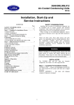
40 RM/RMS 008-034 Packaged
Air-Handling Units
Concepcion-Carrier
Air conditioning
Company
Philippines
Contents
INSTALLATION MANUAL, START-UP &
SERVICE INSTRUCTIONS
Page
Safety Considerations
1
Pre-Installation
Moving and Storage
Rigging
1
1
1
Installation
General
Uncrating
Unit Positioning
Unit Isolation
Refrigerant and Chilled Water Piping Access
Refrigerant Piping
Chilled Water Piping
Condensate Drain
Fan Motor and Drives
Power Supply and Wiring
Connecting Ductwork
1
1
1
1
2
2
2
3
3
4
4
5
Start-Up
5
Service
Panels
Fan Motor Lubrication
Fan Shaft Bearings
Centering Fan Wheel
Fan Shaft Position Adjustment
Individual Fan Wheel Adjustment
Fan Belts
Fan Rotation
Fan Pulley Alignment
Pulley and Drive Adjustment
Condensate Drains
Return Air Filters
Coil Removal / Cleaning
Cleaning Insulation
Replacing Filters
Unbalanced 3-phase Supply Voltage
5
5
5
5
5
5
6
6
6
6
6
7
7
7
7
7
7
Page
40RM Physical Data
40RMS Physical Data
Electrical Data, Standard Motors
Electrical Data, Alternate Motors
Fan Motor Data, Standard Motors
Fan Motor Data, Alternate Motors
Standard Drive Data
Medium Static Drive Data
High Static Drive
Fan Performance Data
Filter Pressure Drop
40RM008-012 Dimensions
40RM016-024 Dimensions
40RM028-034 Dimensions
40RMS008-012 Dimensions
40RMS016-024 Dimensions
40RMS028-034 Dimensions
8
9
10
10
11
11
12
12
13
14 - 16
17
18
19
20
21
22
23
Start-Up Checklist
24-25
SAFETY CONSIDERATIONS
Installation and servicing of air conditioning equipment can be
hazardous due to system pressure and electrical components.
Only trained and qualified service personnel should install, repair or
service air conditioning equipment.
Untrained personnel can perform basic maintenance functions
such as cleaning coils and cleaning and replacing filters. All
operations should be performed by trained service personnel.
Observe precautions in the literature, tags and labels attached to
the unit .
q Follow all safety codes
q Wear safety glasses and gloves. Use quenching cloth and
have fire extinguisher available for all brazing operations.
q
Use care in handling, rigging and setting bulky equipment.
WARNING
Be sure all power is shut off before performing maintenance or
service. More than one disconnect may be present.
Remove plastic wrap. Examine unit for shipping damage. If
shipping damage is evident, file claim with transportation agency.
Remove base skid prior to actual installation.
Check nameplate information against available power supply and
model number description.
UNIT POSITIONING
The unit can be mounted on the floor for vertical application with
return air entering the face of the unit and supply air discharging
vertically through the top of the unit. The unit can be also applied in
a horizontal arrangement with return air entering horizontally and
the supply air discharging horizontally. When applying the unit in a
horizontal arrangement, ensure the condensate drain pan is
located at the bottom center of the unit for adequate condensate
disposal. See Fig. 1 for condensate connections for each position.
Typical positioning and alternate return air locations are shown in
Fig. 1. Alternate return air locations can be used by moving the unit
panel from the alternate return air location to the standard return air
location.
PRE-INSTALLATION
Moving and Storage
To transfer unit from truck to storage site, use a fork truck. Do not
stack units more than 2 high during storage. If unit is to be stored
for more than 2 weeks before installation, choose level, dry storage
site free from vibration. Do not remove plastic wrap or skid from
unit until final installation.
Fig. 1 - Typical Unit Positioning
Rigging
All 40RM/RMS Series units can be rigged by using the shipping
skids. Units are shipped fully assembled. Do not remove shipping
skids or protective covering until unit is ready for final placement;
damage to bottom panels can result. Use slings and spreader bars
as applicable to lift unit.
INSTALLATION
General
Allow 2-1/2 ft at front and side of unit for service clearance and
airflow. For units equipped with an economizer, refer to accessory
installation instructions for additional clearance requirements. Be
sure floor, wall or ceiling support unit weight. See Table 1A, 1B, 1C,
1D for details.
Uncrating
Move unit as near as possible to final location before removing
shipping skid.
IMPORTANT
Do not attempt to install the unit with return air entering top panel
of the unit. Condensate will not drain from unit.
Unit Isolation
Where extremely quiet operation is essential, install isolators
between floor and base of unit or between ceiling and top section
of unit.
Be sure that unit is level and adequately supported. Use channels
at front and sides of unit for reference points when leveling.
Refrigerant and Chilled Water Piping Access
The 40RM/RMS series units come with stub-out pipes for easy
refrigerant and chilled-water piping. These pipes are protruded
outside the units for ready installation. The standard location of
these pipes are at the right side. However, should alternate route of
pipings be required there are also available knock-out holes at the
opposite side of the unit.
Refrigerant Piping
See Tables 1A, 1B, 1D, 1E for refrigerant pipe connection sizes.
For ease in brazing, it is recommended that all internal and external
solder joints be made before unit is placed in final position.
The 40 RM direct-expansion coils have internal factory-installed
thermostatic expansion valves (TXV’s), distributors and nozzles for
use with R-22. Knock-outs are provided in the unit corner posts.
The sensor bulb capillary tubes must be routed from the TXVs
inside the unit through one of the piping access holes. Clamp the
TXV sensor bulb on a vertical position of the suction line, outside
the unit. See Fig. 3.1 and 3.2.
40RM016-034 series evaporator have a face-split design. Ensure
that lower circuit of the coil is first on/last off when connected to the
condensing unit and /or system controls.
External TXV equalizer connections are provided and factory –
brazed into the coil suction manifolds.
If suction line must be horizontal, clamp bulb onto suction line at
least 45 degrees above the bottom at approximately the 4 o’clock
or 8 o’clock position. See Fig. 2.
FOR 40 RM 016 & 024
FOR
40 RM 024
ONLY
Fig. 3.1–Face-Split Coil Suction and Liquid Line Piping
(Typical for 40RM 016/024)
Fig. 3.2–Face-Split Coil Suction and Liquid Line Piping
(Typical for 40RM 028/034)
IMPORTANT
Fig. 2 – TXV Sensing Bulb Location
Note: The 8’o’clock position is shown above
NEVER attach the sensor to the suction manifold. DO NOT mount
the sensor on a trapped portion of the suction line.
pressure created by fans, preventing complete drainage.
Conditions will worsen as filters become dirty.
Install clean-out plugs in traps. Pitch drain line downward to an
open floor drain or sump. Provide service clearance around drain
line to permit removal of panels. Observe all local sanitary codes.
As shipped, the unit’s condensate drain pan is not sloped towards
the drain connection. The pan slope must be changed to pitch
towards the side of the unit with the drain connection. See Fig. 6.
Loosen the 2 screws next to the drain outlet at both ends of the
unit, push drain pan down in the slots near the drain connections,
and up in the slots on the opposite end. Retighten screws. The pan
should have a pitch of at least ¼ in. over its length toward the drain
connection.
Fig. 4 – Typical Evaporator Coil Connections (40RM)
Chilled Water Piping
See Table 1B for chilled water connection sizes. For ease in piping
connection it is recommended that all external fittings be made
before the unit is placed in a final position.
Alternative holes are available on the opposite Post Corner should
the alternate route of pipings are required. To design and install
chilled water piping, consult Carrier System Design Manual. See
Fig. 7 for an example of a typical installation. Recommended
fittings are listed in Table 1B.
To access 40RMS coil vents and drains, remove the unit side panel
over the coil header. Vent and drain plugs are on the top and
bottom of the header, respectively.
Fig. 5 – Condensate Drains
Condensate Drain
Install a trapped condensate drain line to unit connection as shown
in Fig. 5 . Some areas may require an adapter to connect to either
galvanized steel or copper pipe.
Note: A trap must be installed in the condensate drain line to
ensure that the static pressure of fans is balanced with the water
column in the drain line and that the condensate can drain
completely from pan. Without a trap, air can be drawn up drain line
until water level in condensate pan becomes equal to static
Fig. 6 – Drain Slope Adjustments
Fig. 7 - Typical 40RMS Chilled Water Piping
STRAINER
Fan Motor and Drives
Motor and drive packages are factory-installed in all units. The
standard motor and drive packages consist of the following items :
1 – fan motor
1 – adjustable motor pulley
1 – fan pulley
1 – fan belt for 008-024 sizes; 2 for 028-034 sizes
For instructions on changing fan rotation, changing the drive
speeds and adjusting drives. Please refer to Fan Rotation Section.
Fan motors are factory installed on all units. Indoor-fan contactors
are located in the fan contactor box behind the side access panel.
Wire the thermostat according to the label diagram. If the air
handler is a part of the split system, complete the wiring from the
condensing unit to the thermostat.
Power Supply and Wiring
Check the unit data plate to ensure that available power supply
matches electrical characteristics of the unit. Provide a disconnect
switch of size required to provide adequate fan motor starting
current. See Table 4A for unit electrical data.
F
A
N
CONTACTOR
BOX
WIRING
ACCESS
Fig. 9 - Fan Contactor Box ( Cover Removed)
Fig. 8 - Wiring and Service Access ( Side Panel Removed)
Connecting Ductwork
Refer to Carrier System Design Manual for the recommended
design and layout of ductwork. Fig. 10 shows recommended duct
connection to units with two fans.
Most unit service can be performed by removing one or both of the
unit’s side panels. Coil cleaning or removal or insulation cleaning
may require removal of rear, top or bottom panel, depending on the
unit’s orientation. When service is completed, replace unit panels.
Panels
Panels are fastened to unit frame with sheet metal screws. Fan coil
and coil compartment must be sealed tightly after service to
prevent air from bypassing the cooling coil.
Fan Motor Lubrication
Fan motor supplied with unit is permanently lubricated and requires
no further lubrication.
Fan Shaft Bearings
Bearings on 008 – 034 size units have pillow-block bearings (Fig.
Fig. 10 - Typical Fan Discharge Connections for Multiple Fan
Units
START UP
Before starting the unit, check the following and correct as
necessary:
q Is the unit solidly supported ?
q Is fan adjusted for speed and pulley alignment ?
q Are pulleys, motors and bearings securely mounted ?
q Is condensate drain pan pitched for correct drainage ?
q Are coil baffles tight against coil to prevent air bypass ?
q Are all panels securely fastened ?
q Are all electrical connections correct and tight ?
SERVICE
Inspection and maintenance should be performed at regular
intervals and should include the following :
q Complete cleaning of cabinet, fan wheel, cooling coil,
condensate pan and drain and return air grille ( if present).
q Inspection of panels and sealing unit against air leakage.
q Adjustment of fan motor , belt, bearings and wheels.
q Cleaning or replacing of filters.
q Testing for cooling system leaks.
q Checking of all electrical connections.
11) that must be lubricated with suitable bearing grease every 3
months.
Fig. 11 - Fan Shaft, Bearings and Fan Wheel
Centering Fan Wheel
If fan and fan shaft assembly are not properly centered, blades
may scrape against scroll or may create an objectionable whistling
noise. It may be necessary to adjust individual fan wheels or move
the entire fan shaft. See the following sections.
Fan Shaft Position Adjustment
Loosen setscrew or locking collar of each fan shaft bearing. Slide
shaft into correct position and replace locking collar (Fig. 12). To
replace locking collar, push collar up against inner face of the
bearing. Turn collar in direction of the fan rotation until tight, and
tighten setscrew. Tightening locking collar in direction of fan
rotation results in further tightening of collar should setscrew work
itself loose.
diagram on the inside of the motor terminal box cover for proper
reversing procedure.
Fig. 14 - Fan Rotation
Fig. 12 - Fan Shaft Bearing
Individual Fan Wheel Adjustment
Loosen the two locking bolts holding the fan wheel hub to the shaft.
Position fan wheel in center of the fan housing and tighten locking
bolts. Clearance between wheel and housing should be the same
on both sides.
Fan Belts
Motor mounting plate and motor support angles are slotted to
permit both vertical and horizontal adjustments. Adjust belt(s) for
correct deflection by loosening motor mounting bolts, moving
motor/plate assembly forward or back and tightening bolts. Press
down on belt with one finger midway between fan and motor
pulleys to check deflection. For units with motor sizes up to and
including 3.0 hp (2.3Kw), correct deflection is 3/16 in. (4.8 mm). For
larger motor sizes, correct deflection is 1/8 in (3.2 mm). See Fig. 13
Fan Pulley Alignment
Align as follows :
1. Loosen setscrews on pulleys.
2. Align pulleys visually and tighten setscrews on fan pulleys to
lock it in place.
3. Use the methods shown in Fig. 15. To check proper pulley
alignment.
4. If pulleys are not in correct alignment, loosen the motor
holddown bolts and slide the motor axially until the pulleys are
aligned.
5. Tighten the motor holddown bolts.
Pulley and Drive Adjustments
To obtain desired fan speed, refer to fan motor and drive data and
adjust pulley as follows:
1. Remove belt from fan motor pulley after loosening motor from
motor base.
2. Loosen setscrew in moveable flange of pulley. Screw
moveable flange toward fixed flange to increase the fan speed
and away from fixed flange to reduce speed. Before tightening
setscrew, make certain that setscrew is over nearest flat
surface of pulley hub.
Fig. 13 - Fan Motor Mounting
If complete belt replacement is required during servicing , loosen
the motor plate mounting bolts, move motor/plate assembly
towards the fan pulley and pull the belt(s) off the pulleys. Reverse
the procedure with new bolts and readjust deflection.
Fan Rotation
Correct fan rotation with respect to fan outlet is shown in Fig. 14.
To reverse the direction of rotation of a 3-phase fan motor,
interchange any 2 of the power leads. Refer to the connection
Fig. 15 - Fan Pulley Adjustments
CAUTION
Increasing fan speed produces a greater load on motor. Do not
exceed rated capacity of motor.
Condensate Drains
Keep condensate drains free of dirt and foreign matter.
Return-Air Filters
Refer to Replacing Filters Section for filter accessibility and
removal. Replace with clean filters of the sizes listed in Tables 1A –
1D.
Coil Removal
Remove return-air filters. Remove any heavy dirt that may have
accumulated on underside of the coil. Coil can be cleaned more
easily with a stiff brush, vacuum cleaner or compressed air when
coil is dry. If coil is wet or if water is to be used for cleaning, guard
against splashing water on electrical components or damaging
surrounding area. Clean coil baffles as applicable and check for
tight fit to be sure air does not bypass coil.
Cleaning Insulation
The insulation contains an immobilized antimicrobial agent that
helps prevent the growth of bacteria and fungi. It is recommended
to clean the surface of the insulation after every cleaning of the coil
by wiping it with water-soap solution..
Replacing Filters
Filters can be removed and installed from either side of the unit.
1. Remove the filter side cover.
2. Remove old filters by sliding them out one by one from the
filter track.
3. Reverse the procedure to install new filters.
CAUTION
Do not operate unit without air filters.
*Motors are designed for satisfactory operation of nominal voltages
shown. Voltages should not exceed the limits shown in the Voltage
Limits column.
Unbalanced 3-Phase Supply Voltage
Never operate a motor where a phase imbalance in supply voltage
is greater than 2 %. Use the following formula to determine the
percentage of voltage imbalance.
% Voltage Imbalance
= max. voltage deviation from ave. voltage x 100
average voltage
Example:
Supply voltage : 230 – 3 – 60
Voltage Measurements:
Phase A-B = 226
Phase B-C = 233
Phase C-A = 228
Average Voltage = 226 + 233 + 228
3
Average Voltage = 229
Determine maximum deviation from average voltage.
(AB) 229 – 226 = 3
(BC) 233 – 229 = 4
(CA) 229 – 228 = 1
Maximum deviation is 4 V.
Determine % Voltage Imbalance.
= 100 x 4 / 229 = 1.75 %
This amount of phase imbalance is satisfactory as it is below the
maximum allowable 2%.
IMPORTANT
If the supply voltage phase imbalance is more than 2% at main
circuit breaker, contact your utility company.
TABLE 1A - 40 RM PHYSICAL DATA - ENGLISH
UNIT 4O RM
NOMINAL CAPACITY (TONS)
OPERATING WEIGHT (lb)
Base Unit with TXV
FANS
Qty… Diam. (in)
Nominal Air Flow (cfm)
Air flow Range (cfm)
Nominal Motor Hp (Standard Motor)
208/230-3-60 and 460-3-60
Motor Speed (rpm)
208/230-3-60 and 460-3-60
REFRIGERANT
Operating Charge (lb)
(approx per circuit)*
DIRECT EXPANSION COIL
Max Working Pressure (psig)
Face Area (sq ft)
No. of Splits
No. of Circuits per Split
Split Type… Percentage
Rows… Fins / in
PIPING CONNECTIONS (Qty/Size, in)
DX Coil - Suction (ODF)
DX Coil - Liquid Refrigerant (ODF)
Condensate
FILTERS
Quantity… Size (in)
Access Location
LEGEND
TXV - Thermostatic Expansion Valve
* Units are shipped without refrigerant charge.
008
7.5
012
10
016
15
024
20
028
25
034
30
385
405
685
690
1020
1030
3000
22503750
4000
30005000
6000
45007500
8000
600010000
10000
750012500
12000
900015000
1.0
2.0
7.5
7.5
1… 15
2… 15
2… 18
3.0
1725
1745
R 22
3.0
3.0
8.33
15
3…15
2.5/2.5
3.5/3.5
4.5/4.5
5.0/5.0
Enhanced Copper Tubes, Aluminum Sine-WaveFins
435
10.0
17.67
19.88
24.86
29.83
1
2
18
12
13
15
18
Face… 50/50
3…17
3…15
3…17
3…15
1…1-1/8
1…5/8
1…16 x 20 x 2
1…25 x 20 x 2
2…1-1/8
2…1-3/8
2…5/8
1… 1-1/4 ODF
Washable - Factory Supplied
2…16 x 20 x 2
2…25 x 20 x 2
Either Side
1…25 x 13 x 2
4…25 x 20 x 2
TABLE 1B - 40 RMS PHYSICAL DATA - ENGLISH
UNIT 4O RMS
NOMINAL CAPACITY (TONS)
OPERATING WEIGHT (lb)
FANS
Qty… Diam. (in)
Nominal Air Flow (cfm)
Air flow Range (cfm)
Nominal Motor Hp (Standard Motor)
208/230-3-60 and 460-3-60
Motor Speed (rpm)
208/230-3-60 and 460-3-60
CHILLED WATER COIL
Max Working Pressure (psig)
Face Area (sq ft) - Upper
Face Area (sq ft) - Lower
Rows… Fins / in
PIPING CONNECTIONS (Qty/Size, in)
Chilled Water - In
Chilled Water - Out
Condensate
FILTERS
Quantity… Size (in)
Access Location
008
7.5
390
012
10
391
016
15
677
1… 15
028
25
1035
2… 15
3000
22503750
4000
30005000
1.0
2.0
8.3
024
20
683
6000
45007500
034
30
1042
2… 18
8000
600010000
3.0
10000
750012500
12000
900015000
7.5
7.5
1725
1745
Enhanced Copper Tubes, Aluminum Sine-WaveFins
150
9.8
8.3
11.0
12.4
15.5
8.3
8.3
12.4
12.4
3…15
1…1-1/2 ODM
1…1-1/2 ODM
1…16 x 20 x 2
1…25 x 20 x 2
1…1-1/2 ODM
1…1-1/2 ODM
2… 1-1/4 ODF
Washable - Factory Supplied
2…16 x 20 x 2
2…25 x 20 x 2
Either Side
1…2 ODM
1…2 ODM
1…25 x 13 x 2
4…25 x 20 x 2
TABLE 4A - ELECTRICAL DATA, STANDARD MOTORS
FAN MOTOR
UNIT
V*-PH-HZ
VOLTAGE LIMITS
40RM 008
40RMS 008
40RM 012
40RMS 012
40 RM 016
40 RMS 016
40 RM 024
40 RMS 024
40 RM 028
40 RMS 028
40 RM 034
40 RMS 034
208/230 - 3 - 60
460 - 3 - 60
208/230 - 3 - 60
460 - 3 - 60
208/230 - 3 - 60
460 - 3 - 60
208/230 - 3 - 60
460 - 3 - 60
208/230 - 3 - 60
460 - 3 - 60
208/230 - 3 - 60
460 - 3 - 60
187-253
414 - 528
187 - 253
414 - 528
187 - 253
414 - 528
187 - 253
414 - 528
187 - 253
414 - 528
187 - 253
414 - 528
HP
1.0
2.0
3.0
3.0
7.5
7.5
FLA
3.3
1.7
6.3
3.2
8.8
4.49
8.8
4.49
22.0/21.0
10.5
22.0/21.0
10.5
POWER SUPPLY
MINIMUM
MOCP
CIRCUIT AMPS
4.1
15
2.1
15
7.9
15
4.0
15
11.0
15
5.6
15
11.0
15
5.6
15
27.5/26.3
45/45
13.1
20
27.5/26.3
45/45
13.1
20
TABLE 4B - ELECTRICAL DATA, ALTERNATE MOTORS
FAN MOTOR
UNIT
40RM 008
40RMS 008
40RM 012
40RMS 012
40 RM 016
40 RMS 016
40 RM 024
40 RMS 024
40 RM 028
40 RMS 028
LEGEND :
FLA
MOCP
V*-PH-HZ
VOLTAGE LIMITS
208/230 - 3 - 60
187 - 253
2.0
208/230 - 3 - 60
187 - 253
3.0
208/230 - 3 - 60
460 - 3 - 60
208/230 - 3 - 60
460 - 3 - 60
208/230 - 3 - 60
460 - 3 - 60
187 - 253
414 - 528
187 - 253
414 - 528
187 - 253
414 - 528
HP
5.0
5.0
10.0
FLA
6.3
3.2
8.8
4.49
15.2/14.4
7.2
15.2/14.4
7.2
26.4/25.0
12.5
Full Load Amps
Maximum Overcurrent Protection, Amps (Circuit Breaker)
Note: For 3-phase motors, use circuit breakers with common trip bar to prevent single pahsing defect.
POWER SUPPLY
MINIMUM
MOCP
CIRCUIT AMPS
7.9
15
4.0
15
11.0
15
5.6
15
19.9/18.0
30/30
9.0
15
19.9/18.0
30/30
9.0
15
33.0/31.3
55/55
15.6
25
TABLE 5A - FAN MOTOR DATA, STANDARD MOTOR
UNIT
208/230 - 3 - 60 and 460 - 3 - 60
Speed (rpm)
Hp
Frame
Shaft Dia.
40 RM 008
40 RMS 008
40 RM 012
40 RMS 012
40 RM 016
40RMS 016
40RM 024
40 RMS 024
40RM 028
40RMS 028
1725
1.0
2.0
56 Y (NEMA)
7/8"
7/8"
7/8"
40 RM 034
40RMS 034
1745
7.5
132S(IEC)
38 mm
3.0
7/8"
TABLE 5B - FAN MOTOR DATA, ALTERNATE MOTOR
UNIT
40 RM 008
40 RMS 008
208/230 - 3 - 60 and 460 - 3 - 60
Speed (rpm)
Hp
Frame
Shaft Dia.
2.0
40 RM 012
40 RMS 012
40 RM 016
40RMS 016
40RM 024
40 RMS 024
1725
40RM 028
40RMS 028
40 RM 034
40RMS 034
1745
3.0
56 Y (NEMA)
7/8"
7/8"
5.0
S184T (NEMA)
1-1/8"
1-1/8"
10
132M (IEC)
38 mm
TABLE - Standard Drive Data, 60 Hz - English
UNIT
MOTOR DRIVE
Motor Pulley Pitch Diameter (in)
Pulley Factory Setting
Full Turns Open
FAN DRIVE
Pulley Pitch Diameter (in)
Pulley Bore (in)
Belt No. - Section
FAN SPEEDS (rpm)
Factory Setting
Range
Max. Allowable Speed (rpm)
Max. Full Turns From
Closed Position
40RM
40 RMS
008
40RM
40 RMS
012
40RM
40 RMS
016
40RM
40 RMS
024
40RM
40 RMS
028
40RM
40 RMS
034
3.4 - 4.3
3.4 - 4.3
3.4 - 4.3
3.4 - 4.3
3.9 - 5.1
3.9 - 5.1
5
5
4
4
4
4
8.8
1
1 - A41
8.8
1
1 - A41
10
1
1 - B40
10
1
1 - B40
10
1 15/16
2 - B39
10
1 15/16
2 - B39
647
549 - 745
1200
764
666 - 863
1200
632
537 - 728
1200
771
679 - 863
1200
752
682 - 841
1100
752
674 - 831
1100
5.5
5.5
5.5
5.5
5.5
5.5
TABLE - Medium Static Drive Data, 60 Hz - English
UNIT
MOTOR DRIVE
Motor Pulley Pitch Diameter (in)
Pulley Factory Setting
Full Turns Open
FAN DRIVE
Pulley Pitch Diameter (in)
Pulley Bore (in)
Belt No. - Section
FAN SPEEDS (rpm)
Factory Setting
Range
Max. Allowable Speed (rpm)
Max. Full Turns From
Closed Position
40RM
40 RMS
008
40RM
40 RMS
012
40RM
40 RMS
016
40RM
40 RMS
024
40RM
40 RMS
028
40RM
40 RMS
034
3.4 -4.3
3.4 - 4.3
3.4 -4.3
3.4 -4.3
3.9-5.1
3.9-5.1
5
5
4
4
4
4
8.8
1
1 - A41
8.8
1
1 - A41
10
1
1 - B40
10
1
1 - B40
10
1 15/16
2 - B39
10
1 15/16
2 - B39
841
733 - 949
1200
841
733 - 949
1200
842
742 - 943
1200
881
798 - 984
1200
881
798 - 984
1100
881
798 - 984
1100
5.5
5.5
5.5
5.5
5.5
5.5
TABLE - High Static Drive Data, 60 Hz - English
UNIT
40RM
40 RMS
008
MOTOR DRIVE
Motor Pulley Pitch Diameter (in)
3.4 -4.3
Pulley Factory Setting
5
Full Turns Open
FAN DRIVE
Pulley Pitch Diameter (in)
6.0*
Pulley Bore (in)
1
Belt No. - Section
1 - A41
FAN SPEEDS (rpm)
Factory Setting
1121
Range
978 - 1200**
Max. Allowable Speed (rpm)
1200
Max. Full Turns From
5.5
Closed Position
40RM
40 RMS
012
40RM
40 RMS
016
40RM
40 RMS
024
40RM
40 RMS
028
40RM
40 RMS
034
3.4 - 4.3
3.4 -4.3
3.4 -4.3
3.9-5.1
3.9-5.1
5
4
4
4
4
6.0
1
1 - A41
7.9
1
1 - B40
7.4
1
1 - B40
8.6
1 15/16
2 - B39
8.6
1 15/16
2 - B39
1121
978 - 1200*
1200
1060
950 - 1171
1200
1118
1014 - 1200*
1200
1024
873 - 1075
1100
1024
873 - 1075
1100
5.5
5.5
5.5
5.5
5.5
** It is possible to adjust drive so that the fan speed exceeds maximum allowable. DO NOT EXCEED 1200 rpm.
Table - Fan Performance Data - 0.0 - 0.6 in. wg. ESP - English
UNIT
40RM
40RMS
008
40RM
40RMS
012
40RM
40RMS
016
40RM
40RMS
024
40RM
40RMS
028
40RM
40RMS
034
Static Pressure
AIRFLOW
(CFM)
2,250
2,600
3,000
3,400
3,750
3,000
3,500
4,000
4,500
5,000
4,500
5,300
6,000
6,800
7,500
6,000
7,000
8,000
9,000
10,000
7,500
8,750
10,000
11,250
12,500
9,000
10,500
12,000
13,500
15,000
0.0
RPM
359
415
478
542
598
444
518
592
666
740
391
460
521
590
651
503
586
670
754
838
412
481
549
618
687
471
550
628
707
785
0.2
BHP
0.32
0.45
0.62
0.82
1.03
0.58
0.82
1.11
1.44
1.83
0.51
0.80
1.13
1.60
2.10
1.07
1.64
2.37
3.28
4.39
1.15
1.76
2.55
3.52
4.71
1.78
2.72
3.93
5.44
7.27
RPM
472
516
569
624
673
541
604
669
735
803
495
551
602
663
718
587
660
735
812
891
492
550
610
672
735
539
608
679
752
826
0.4
BHP
0.44
0.57
0.75
0.95
1.17
0.71
0.95
1.25
1.59
1.98
0.75
1.08
1.43
1.93
2.45
1.37
1.98
2.74
3.69
4.83
1.53
2.17
2.99
4.00
5.22
2.17
3.15
4.40
5.94
7.81
Legend
BHP
ESP
-Brake Horsepower Input to Fan
-External Static Pressure
Notes:
1. Maximum allowable fan speed is 1100 rpm for unit sizes 028 and
034; 1200 for all other sizes.
2. Fan performance is based on deductions for wet coil, clean 2-in.
filters, and unit casing. See table for factory-supplied filter
pressure drop.
RPM
560
599
645
695
740
621
677
736
797
861
581
629
675
730
779
661
726
795
867
941
568
616
669
725
783
604
665
730
797
867
0.6
BHP
0.55
0.68
0.86
1.08
1.29
0.83
1.08
1.38
1.72
2.12
1.00
1.35
1.73
2.26
2.81
1.67
2.31
3.12
4.09
5.27
2.00
2.66
3.50
4.53
5.78
2.63
3.64
4.92
6.49
8.39
RPM
634
669
712
758
800
691
742
797
854
914
657
700
741
791
837
727
787
851
918
988
640
680
726
777
830
667
720
779
841
907
BHP
0.65
0.79
0.98
1.20
1.42
0.94
1.20
1.51
1.86
2.26
1.25
1.63
2.04
2.59
3.16
1.97
2.65
3.49
4.50
5.70
2.56
3.22
4.07
5.12
6.38
3.17
4.18
5.48
7.08
9.01
Table - Fan Performance Data - 0.8 - 1.4 in. wg. ESP - English
UNIT
40RM
40RMS
008
40RM
40RMS
012
40RM
40RMS
016
40RM
40RMS
024
40RM
40RMS
028
40RM
40RMS
034
AIRFLOW
(CFM)
2,250
2,600
3,000
3,400
3,750
3,000
3,500
4,000
4,500
5,000
4,500
5,300
6,000
6,800
7,500
6,000
7,000
8,000
9,000
10,000
7,500
8,750
10,000
11,250
12,500
9,000
10,500
12,000
13,500
15,000
0.8
RPM
700
732
773
815
855
753
801
853
907
964
725
764
801
847
890
789
844
904
967
1034
710
742
782
827
876
728
774
827
885
947
1.0
BHP
0.75
0.90
1.09
1.31
1.60
1.05
1.32
1.63
1.99
2.39
1.50
1.91
2.34
2.92
3.52
2.28
2.99
3.86
4.90
6.14
3.22
3.86
4.70
5.76
7.04
3.78
4.79
6.09
7.71
9.66
RPM
759
790
828
869
906
809
855
904
956
1010
787
823
858
901
941
846
898
954
1014
1077
776
802
836
876
922
788
827
874
928
986
1.2
BHP
0.86
1.01
1.20
1.43
1.66
1.17
1.44
1.75
2.12
2.53
1.76
2.20
2.65
3.26
3.88
2.59
3.33
4.23
5.31
6.85
3.98
4.58
5.40
6.45
7.74
4.46
5.45
6.76
8.38
10.35
Legend
BHP
ESP
-Brake Horsepower Input to Fan
-External Static Pressure
Notes:
1. Maximum allowable fan speed is 1100 rpm for unit sizes 028 and
034; 1200 for all other sizes.
2. Fan performance is based on deductions for wet coil, clean 2-in.
filters, and unit casing. See table for factory-supplied filter
pressure drop.
RPM
814
843
879
918
954
862
906
953
1003
1055
845
878
911
951
990
900
948
1001
1059
1120
840
860
889
925
966
845
878
921
970
1024
1.4
BHP
0.96
1.11
1.32
1.55
1.78
1.28
1.56
1.88
2.24
2.66
2.02
2.48
2.96
3.60
4.24
2.90
3.67
4.61
5.72
7.02
4.83
5.38
6.17
7.21
8.49
5.22
6.18
7.47
9.10
11.07
RPM
865
893
928
965
1000
911
953
999
1047
1097
899
930
961
999
1036
950
996
1047
1102
1160
903
917
941
972
1010
901
928
966
1011
1062
BHP
1.06
1.22
1.43
1.66
1.90
1.39
1.67
2.00
2.37
2.79
2.29
2.78
3.28
3.94
4.60
3.21
4.02
4.99
6.13
7.46
5.79
6.26
7.01
8.02
9.29
6.07
6.98
8.24
9.86
11.84
Table - Fan Performance Data - 1.6-2.4 in. wg. ESP - English
UNIT
40RM
40RMS
008
40RM
40RMS
012
40RM
40RMS
016
40RM
40RMS
024
40RM
40RMS
028
40RM
40RMS
034
AIRFLOW
(CFM)
2,250
2,600
3,000
3,400
3,750
3,000
3,500
4,000
4,500
5,000
4,500
5,300
6,000
6,800
7,500
6,000
7,000
8,000
9,000
10,000
7,500
8,750
10,000
11,250
12,500
9,000
10,500
12,000
13,500
15,000
1.6
RPM
913
940
973
1010
1043
958
998
1042
1089
1138
951
980
1009
1045
1080
999
1042
1091
1143
1200
963
972
991
1019
1053
955
978
1011
1052
-
1.8
BHP
1.16
1.33
1.54
1.78
2.02
1.5
1.79
2.12
2.50
2.92
2.56
3.08
3.60
4.28
4.97
3.53
4.37
5.37
6.54
7.91
6.83
7.22
7.91
8.89
10.15
6.98
7.84
9.07
10.67
-
RPM
958
984
1017
1052
1084
1002
1041
1084
1129
1177
999
1027
1055
1089
1123
1045
1086
1133
1183
1021
1025
1040
1064
1095
1008
1026
1055
1092
-
2.0
BHP
1.27
1.43
1.65
1.89
2.13
1.61
1.90
2.24
2.62
3.05
2.84
3.38
3.92
4.63
5.34
3.85
4.72
5.75
6.96
7.98
8.26
8.89
9.83
11.05
7.98
8.76
9.95
11.52
-
Legend
BHP
ESP
-Brake Horsepower Input to Fan
-External Static Pressure
Notes:
1. Maximum allowable fan speed is 1100 rpm for unit sizes 028 and
034; 1200 for all other sizes.
2. Fan performance is based on deductions for wet coil, clean 2-in.
filters, and unit casing. See table for factory-supplied filter
pressure drop.
RPM
1001
1027
1058
1092
1124
1044
1082
1124
1168
1046
1072
1098
1132
1164
1089
1129
1173
1078
1078
1089
1060
1073
1098
-
2.2
BHP
1.37
1.54
1.76
2.00
2.25
1.72
2.02
2.36
2.74
3.12
3.68
4.24
4.98
5.71
4.17
5.07
6.13
9.21
9.38
9.93
9.05
9.74
10.88
-
RPM
1042
1067
1098
1131
1162
1084
1122
1162
1091
1116
1141
1173
1131
1169
-
2.4
BHP
1.47
1.65
1.87
2.12
2.37
1.83
2.13
2.48
3.41
3.99
4.57
5.33
4.50
5.43
-
RPM
1123
1159
1199
1133
1157
1181
1172
-
2.4
BHP
1.94
2.25
2.60
3.70
4.30
4.91
4.83
-
Factory-Supplied Filter Pressure Drop - English
Unit
40 RM
40 RMS
008
40 RM
40 RMS
012
40 RM
40 RMS
016
40 RM
40 RMS
024
40 RM
40 RMS
028
40 RM
40 RMS
034
Airflow
(Cfm)
2,250
3,000
3,750
3,000
4,000
5,000
4,500
6,000
7,500
6,000
8,000
10,000
7,500
10,000
12,500
9,000
12,000
15,000
Press. Drop
(in. wg.)
0.07
0.11
0.15
0.11
0.17
0.23
0.08
0.12
0.17
0.12
0.19
0.26
0.15
0.22
0.30
0.19
0.29
0.40
START-UP CHECKLIST
(SPLIT SYSTEMS WITH 40RM/RMS UNITS)
A. Preliminary Information
OUTDOOR:
MODEL NO.
SERIAL NO:
INDOOR :
MODEL NO.
SERIAL NO:
ADDITIONAL ACCESSORIES
B. Pre - Start-Up
OUTDOOR UNIT
Is there any shipping damage?
If so, where :
(Y/N)
Will this damage prevent unit start-up?
Check power supply. Does it agree with unit?
Has the ground wire been connected?
Has the circuit protection been sized and installed properly?
Are the power wires to the unit sized and installed properly?
Have the compressor holddown bolts been loosened?
(Y/N)
(Y/N)
(Y/N)
(Y/N)
(Y/N)
(Y/N)
CONTROLS
Are thermostat(s) and indoor fan control wiring connections made and checked?
Are all wiring terminals (including main power) tight?
Have outdoor unit crankcase heater been energized for 24 hours?
(Y/N)
(Y/N)
(Y/N)
INDOOR UNIT
Has water been placed in drain pan to confirm proper drainage?
Are proper air filters in place?
Have fan motor pulleys been checked for proper alignment?
Do fan belts have proper tension?
(Y/N)
(Y/N)
(Y/N)
(Y/N)
PIPING
40RM
Are liquid solenoid valves located at the indoor unit coils as required?
Have leak checks been made at compressors, condensers, indoor coils,
thermostatic expansion valves, solenoid valves, filter driers and fusible plugs
with a leak detector?
Locate, repair, and report leaks.
Have all compressor service valves been fully opened (backseated)?
Are the compressor sight glasses showing the correct levels?
40RMS
Has air been bled from the system?
Have leak checks been made at compressors, chillers, valves and indoor coils?
Locate, repair and report any leaks.
(Y/N)
(Y/N)
(Y/N)
(Y/N)
(Y/N)
(Y/N)
CHECK VOLTAGE IMBALANCE
Line-to-line Volts
AB______ V
AC______ V
BC______ V
(AB + AC + BC)/3 = Average Voltage =
________ V
Maximum deviation from average voltage = ________ V
Voltage imbalance = 100 x (maximum deviation)/(average voltage) =
_______ %
If over 2% voltage imbalance, DO NOT ATTEMPT TO START SYSTEM!
CALL LOCAL POWER COMPANY FOR ASSISTANCE.
C. Start-Up
Check evaporator fan speed and record.
After at least 10 minutes running time, record the following measurements.
COMP A1
COMP B1
Oil pressure
Suction Pressure
Suction Line Temp
Discharge Pressure
Discharge Line Temp
Outdoor Unit Entering Air Temp
Outdoor Unit Leaving Air Temp
Indoor Unit Entering Air DB Temp
Indoor Unit Entering Air WB Temp
Indoor Unit Leaving Air DB Temp
Indoor Unit Leaving Air WB Temp
Outdoor Unit Entering Water Temp (40RMS only)
Outdoor Unit Leaving Water Temp (40RMS only)
Indoor Unit Entering Water Temp (40RMS only)
Indoor Unit Leaving Water Temp (40RMS only)
Compressor Amps (L1/L2/L3)
Check the compressor oil level sight glasses; Are the glasses showing
oil level at 1/8 to 1/3 full?
NOTES:
____/____/____
____/____/____