1
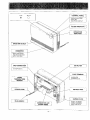
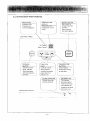
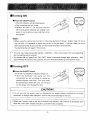
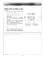
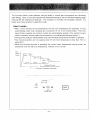
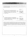
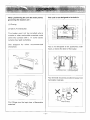
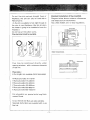
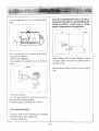
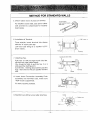
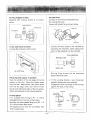
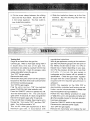
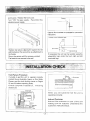
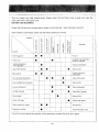
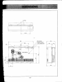
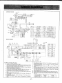
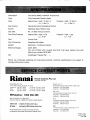
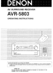
How to use vour
Space ~ e a i e r
Energysaver'" Heater
RHFE-1004FDT
Customer
-page
2
Installer
-page
13
This appliance must be installed correctly by an authorised person, and
the installation must conform with the following local regulations (if
applicable):
Manufacturer's Installation Instructions
Local Gas Fitting Regulations
Municipal Building Codes
AS 5601lAG 601 Gas Installations Code
Any other relevant Statutory Regulation
Your 1004 FDT has been approved by the Australian Gas Association
AGA Approval Number:5941
The Energysaver RHFE-1004FDT includes an option so that operation of the appliance
automatically stops after a fixed time period.
It is possible to choose any one of seven time periods. The periods are : 1, 2, 3, 6, 8, 10 or 1 2
hours.
This option must be activated by a qualified person or trained Rinnai service person
Fixed time period operation is ideally suited to classroom situations, clubs, meeting halls, and
other areas where a limit is required on the length of time theappliance operates.
The feature can provide substantial energy savings in cases where users are likely to forget to turn
the appliance off when they leave the room after meetings or lessons.
If a power failure occurs at any time during operation, the appliance will remain OFF once the
power is re-instated. The ONIOFF button must be pressed to re-ignite the appliance.
Contact Rinnai on one of the telephone numbers listed on the back cover of this booklet for further
advice.
Customers Operating Information
to operate the ~~~t~~ ....................................................................................... 8
Adjusting Temperature ............................................................................................. 9
HOW
Economy Mode ......................................................................................................10
......................................................................................................11
Other Operating \"formation ....................................................................................
12
Function Lock
Installation
...............................................................................................................13
installation Instructions ..........................................................................................16
Sleeve and Manifold Installation ................................................................................. 17
Fitting Unit ............................................................................................................ 19
Testing ...............................................................................................................20
Installation Check ................................................................................................... 21
Care of your 1004 FDT ..........................................................................................22
Pre-Service Check ................................................................................................ 23
ti^^
Error Messages ...................................................................................................... 24
Safety Devices
...................................................................................................... 25
Product Specifications
......................................................................................................... 26
Wiring Diagram ...................................................................................................... 27
Block Diagram ......................................................................................................27
Guarantee Information ............................................................................................. 30
Specifications ...................................................................................................... 31
Service Contact Points............................................................................................. 31
Dimensions
Push button ignition : Only one touch of the ON 1 OFF button is required to operate the heater.
7 step automatic heat control with electronic thermostat. The fan is also controlled by the
thermostat.
Economy mode : An energy saving feature that reduces the room temperature by 3"c over a 90
minute interval.
Lockable Control Panel Lid : The 1004 FDT has a lockable Control Panel Lid which is ideal for
commercial use. This feature is great for applications where safety is paramount or when the unit
is required to be set once and left alone. Two keys are also supplied with the unit.
Function Lock : Prevents children from altering heater settings whilst running, or from activating
the heater when turned off. This feature is utilised if the Control Panel Lid is unlocked.
Heater Filter Indicator : When the heater filter becomes covered with dust and the temperature
inside the appliance rises, the heater filter indicator will flash indicating that cleaning is necessary.
The integral humidifier tray can be filled with water as required to raise the humidity level in the
room.
Room Sealed : Air for combustion is taken from the outside and the flue product is exhausted
outside, keeping the room air clean.
Quality
Endorsed
Company
150 0002 L a lgsl
D
The Australian
Gas Assoc~el\an
Slmdardr ruslralla
- .
RATING PLATE
SERIAL NUMBER.
GAS TYPE, ETC.
ALL BU'TTONS BEEP WHEN OPERATED.
( DISPLAY
Z~~FRG~]
(INDKIndicates
ATO"]
which
temperature is
currently displayed.
?
L
<
L
1 I
BUTON
Main switch for
turning heater ON
and OFF.
Easy operation.
One touch ignition.
Shows either the
temperature or error
codes.
\
1
t
PANEL)
(CONTROL
ONIOFF
,
1
I
Selects Economy
Mode. lndicator
illuminates green
when this feature is
2
Locks all controls
when pressed.
lndicator illuminates
1 green when this
k e a t u r e is on.
J
7
-
I
TEMPERATURE
BUnONS
Used to adjust
temperature setting
up and down.
PLTER
INDIGG) /
=;Flashes when filter
requires cleaning.
(INDICATOR DISPLAY)
\
Function Lock
(,,
II
illuminates green
when the unit is on.
The indicator will
bhangeto;d
when
the burner is on.
,
I,
,
I
,,/
I
Do not use for any other purpose except
These clearances should be maintained at all
times.
Do not allow curtains or other flammable
materials to come into contact with the
heater.
Keep flarnrnable materials, trees shrubs etc.
away from flue terminal.
Do not store flarnrnable products near the
unit.
Supervise children near heater.
'
Flue Terminal
Do not allow young children or the infirm to
sleep directly in front of the heater.
Don't allow children to 'post' articles in the
louvres.
Don't place any articles containing liquids on
top of the heater.
Don't spray aerosols on the heater whilst it is
in operation.
Most aerosols contain butane gas and can be
a fire hazard if used near this heater when in
use.
Do not place articles on or against the heater.
Do not sit on this heater.
T u r n i n g ON
.Press the ONIOFF button
The ON indicator will illuminate green.
The convection fan will rotate.
Ignition will take 5-10 seconds and the
ON/Combustion indicator will change from
green to red to let you know that the burner
has ignited.
Note :
When using the unit for the first time or after long periods of disuse, ignition may not occur
the first time it is operated as there may be air in the gas pipes. If ignition does not occur
after approximately 30 seconds the unit will cease operation automatically.
Try operating the unit again if this occurs.
'
The unit may make noises after ignition /extinction. This is the inside of the unit expanding
and contracting and is normal.
The heater will not ignite if the "ON / O F F ' button is pressed straight after extinction. After
approximately 20 seconds has passed. the unit will automatically go into ignition mode.
'
/'
T u r n i n g OFF
.Press the ONlOFF button
The ON /Combustion indicator will go out.
After t h e indicator has gone out, the
convection fan will continue to rotate for
several minutes, then stop. This 1s to lower
the temperature within the unit. Do not pull
out the power cord during this time.
ON I OFF
CAUTION !
Do not pull out the power cord or disconnect the power during combustron to cause
extinction, or straight after extinction, as this may cause damage to the unit.
When the Function Lock is set, the Function Lock indicator will continue to illuminate even
when the unit is OFF and the Function Lock will not be cancelled.
Displaying, setting and adjusting the room
temperature can only be done when the heater is
operating.
When the unit is first-operated, the room
temperature is set at 22C.
Set the desired room temperature with the
up and down buttons while looking at the
display section.
The "Set Temp" can be set to "C' or between
"16"
" 2 6 , or "H" (continuous combustion
on High).
The "Room Temp" will display "L" (when
" 3 0 (at intervals of
lower than I T ) , "1"
1"C), or " H (when higher than 30%).
Once a temperature is set, it will be stored in
the microcomputer's memory.
q
"
"t Temp 0
Room Temp 0 , )
,1
-
-
Press to lower
the temperature
Press to raise
the temperature
Note :
Rooms may not arrive at the set temperature
due to the construction of the room, the
location of the unit, or external temperatures.
If the heater does not ignite then the pre-set temperature may not be set to a setting which is
higher than the actual room temperature.
The Economy Mode, when selected, has the ability to reduce gas consumption and ultimately
save energy. Once a room has reached the desired temperature, the unit will automatically begin
reducing the set temperature gradually. This reduction is normally not noticeable, however, it is
purely your choice whether to select this mode.
How it works :
After a room reaches the set temperature, the set room temperature will decrease 3 times
automatically, each time, dropping by a maximum of 1°C in 30 minute blocks. From the
second time onwards, the comfort control will automatically operate. (The comfort control
alters combustion and fan speed more frequently to counteract the feeling of cold air. )
The Economy indicator will illuminate to let you know that the Economy Function is selected.
The Economy function will not operate when the set room temperature is less than 16-C or
above 26°C.
When the Economy function is operating, the current room temperature may be shown as
being lower than the set room temperature, however, this is normal.
Set
Room
Temp
II
i4
Comfort Control
"Economy"indicator iiluminates
Set Temp 1:.
j
..~
&,..
Room Temp
\I/
-0-
Ecanarny
Temp A
V control
LrO-
Funcllon Lock
-
The Function Lock will help to prevent accidental operation as well as small children from
altering the heater settings.
Set T e m p
o
Room T e m p 0
The Function Lock can be operated either when the
heater is running, or in the "stand by" mode, by
pressing the up and down buttons simultaneously.
The Function is activated and the Function Lock
~ndicatorwill glow.
Set T e m p
o
Room T e m p 0
To de-activate the Function Lock, simply press both
arrow buttons simultaneously for 2 seconds and the
Function Lock indicator will go out. The lock can be
de-activated at any time in this way.
I
I
Economy
ction La
'When
the Function lock is activated during normal operation all heater controls other than the>
OFF switch will be locked. Deactivating the lock releases the controls. If the lock is activated
whilst the heater is turned OFF, then all heater functions will be locked. If the heater is turned
OFF whilst the Function lock is activated, it cannot be turned ON again until the lock is
deactivated.
J
.
HUMIDIFIER TRAY
Your 1004FDT is fitted with an enamelled tray
behind the air outlet so that you can humidify the
air. To fill the tray, open the door as shown in the
diagram and pour water into the tray using the
spout built into the door.
The air will be humidified as it passes over the
water in the tray. DO NOT FILL THE TRAY
WHILST THE UNIT IS IN OPERATION. CLOSE
THE DOOR AFTER FILLING. The 1004FDT is a
very high efficiency appliance. During operation
a small amount of water is produced in the flue
tubes. This drains into the enamel tray. It is
quite normal for a small quantity of water to
remain in the bottom of the tray. If you are using
the humidifier, it will need filling about once a day
during the peak heating season.
.
Humidifier Tray
I
,
Door
\ Filler
Spout
Do not force door open too far.
Close door during operation.
FAN FILTERS
To protect the fan from dust and lint, the
1004FDT is fitted with 2 fan filters. They are
located at the top, rear of the unit. To clean, pull
the filters out of the unit and remove dust with a
soft brush or a vacuum cleaner. Re-fit filters
after cleaning. Your 1004FDT has a filter clean
warning indicator that will illuminate when
required, however, weekly cleaning is
recommended during the peak heating season.
Filler
....
....
ON-Q
O U T S I D E FLUE
On cold days steam may be discharged from the flue outlet. This is normal with a high
efficiency appliance and does not indicate any fault.
'The
heater and its flue must be installed correctly by an authorised person, and the>
installation must conform to all local regulations.
The installation also must comply with the instructions supplied by Rinnai.
This heater must be serviced, installed and removed by an authorised person.
No parts or functions should be modified or permanently removed from the heater or its flue.
When positioning the unit the main points
governing the location are :
This unit i s not designed t o be built in.
r-
(1) Flueing
(2) Warm Air Distribution
This heater must not be installed where
curtains or other combustible materials could
come into contact with it. In some cases
curtains may need restraining.
See diagram for other recommended
clearances.
r
i
1
Flue is not designed to be positioned under
floors, or below the level of the heater.
Flue terminal should be positioned away from
flammable materials.
Flue fittings must be kept clear of flammable
materials.
Do not flue into natural draught flues or
fireplaces, this unit can only be used with a
Rinnai flue kit.
(A flue kit is available to flue right through to
the rear of most fireplaces Use this kit when
the heater is going to be installed in front of a
fireplace.)
Do not flue unit into other rooms.
Flue terminal must be outside.
Standard installation of flue manifold.
Diagram below shows minimum clearances
and distances from obstructions.
Also check AG601 and 1 or local regulations.
7
I
Flue sizes :
6 flue lengths are available (Sold Separately)
AA flue suits walls 75-1 15mm
A flue suits walls 115-240rnm
B flue suits walls 240-400mrn
C flue suits walls 400-600mm
D flue suits walls 600-800mm
E flue suits walls 800-1000mm
For information on special extra long flues,
contact Rinnai.
Co-ax internal wall flues are also available.
Separate instructions are supplied with co-ax
flue kits.
Flammable
1
I
Side Clearances.
Flue may be p o s i t i o n e d directly under
opening windows. with a minimum clearance
of 150 rnm.
-
Do not install the unit in an unusually dusty
area.
FOR W E A T H E R B O A R D W A L L S D R I L L
THROUGH CENTRE OF WEATHERBOARD
FROM OUTSIDE, T H E N D R I L L FROM
INSIDE THROUGH PLASTERBOARD.
I
Use flue guard i f the terminal is easily
accessible to children.
Check local regulations.
Flue guards are available as an optional
extra.
GUARD
Floor must be level.
Do not use electrical extension cords to
connect unit to power supply.
Keep the power cord away from the flue
Flue manifold position.
Centre of hole for flue manifold can be drilled
anywhere within the shaded area.
(To avoid studs etc.)
I
I
When drilling the flue hole, check for water
and gas pipes and electric cables before
starting to drill.
Use an 80mm (8cm) drill for hole through
wall.
T h e following components are supplied with your 1004FDT.
wall clips
Plastic tie for air inlet
connection .............................. 1
Flue Adapter ........................
Air Inlet Hose ........................1
@
I
Screws
2
Keys ....................................... 2
Back Cover .......................... -7
Wall Clip ................................. 2
Flue Manifold ........................ 3
Terminal tube ........................3
Insulation Clip ........................ 1
a(
Flue Locking Clamp ............ 2
L ............ 1
s ............ 1
p
Back Cover Set .....................1
Flue Lock Stopper ...............1
a23
Insulation Clip ........................1
CJ
Isi
Instructions ...........................
1
(OPTIONAL FLOOR AND WALL BRACKETS ARE AVAILABLE FOR COMMERCIAL INSTALLATIONS)
Check unit supplied is correct for the gas type in your area.
Refer to local gas authority for confirmation of gas type if in doubt.
Refer to data plate located inside front panel.
Check for damage. if the unit is damaged contact your supplier or Rinnai.
Do not install a damaged unit before checking with your supplier.
METHOD FOR STANDARD WALLS
1
5. Check rubber seal is in place on terminal.
For weather board walls, add spare rubber
seal provided to compensate for weather
board angle.
I
seal here)
6. Installation of Terminal
From outside, insert terminal into sleeve
with the " A mark at the top.
Left hand side fixing tie is marked "LEFT"
(from inside) .
7. Attaching Ties
Cu: (leave 20mm free)
Pull hard on left and right hand side ties.
clip ties over lugs inside sleeve.
You should be able to pull the ties 2 or 3
slots past the starting point.
Cut the ties. leaving about 20mm past the
lugs. Bend ties so they are parallel with the
wall.
8. Insert Inner Connection Assembly Push
assembly into terminal tube, make sure
"TOP mark is uppermost.
Fix with 3 screws ~rovided.
9. Manifold can still be turned after attaching
Outlet
Rubber cap
.-
Fix Flue Adapter t o Flue.
Manifold with Locking Clamp S as shown
below.
Air lnlet Hose
Connect Air lnlet Hose to Manifold Inlet.
Do not kink the hose.
Secure with plastic tie as-shown below.
Locking clamp S
d
7
,Flue
Manifold
Flue Adapter
Fit Air inlet Hose t o heater.
Fix Side Back Spacers with screws
1. Connect the flue outlet to the manifold by
extending the stainless steel sliding tube
until it is fully inserted into the manifold.
I
Flue Manifold
I
Sliding Tube
\
Sliding Tube s h o u l d n o t be extended
beyond the RED LINE.
Place top back spacer i n position.
Mark the position of the top edge of the top
spacer on the wall. Move the heater away
from the wall. Mark centre lines 20mm down
from the top edge mark, and 12mm in front
the left and right hand sides of the top spacer.
Attach wall brackets at the marked Dosition.
2. Fit the Locking Clamp L over connection
between sliding tube and manifold.
Engage the hook and rotate it until it snaps
against the body of the clamp.
Flue outlet
Fit lnlet Elbow
Fit a suitable inlet fitting to R1 1 2 15mm
threaded fitting on the rear of the heater.
Normally, the most suitable fitting is an RC 1 1 2
15 X 15mm copper flare elbow.
The appliance can then be connected with
15mm copper tube.
-.
Hook,.'
Locking
clamp
\
Locking
Clamp
3. Fit the screw clamp between the sliding
tube and the flue elbow. Secure with the
4 mm screw supplied. The flue outlet is
now locked into position.
Locking Clamp L
Locking Clamp S
4. Slide the insulation sleeve up to the flue
manifold. slip the securing clip over the
sleeve as shown.
Fit clip
Slide Insulation sock
Flue Outlel tube --_
Flue elbow
Testing Unit
Purge air and swarf from the gas line.
Connect gas. Refer to AGA pipe sizing chart if
in doubt about the size of the gas line.
Connection can easily be reached from the top
and rear of the unit. Check for escapes, using
soapy water after turning the gas on.
Turn "OFF' the gas supply.
Remove the front cover.
Remove the test point screw from the pressure
test point on the front of the main solenoid valve
and connect a pressure gauge.
Turn " O N the gas supply.
Plug the unit in and turn "ON" the electrical
power (CAUTION: 240 Volts inside the unit).
Press the "ONIOFF switch to operate the unit.
Turn the thermostat to "HI". The unit should
ignite within 10 seconds. If it does not ignite the
first time it will spark again after 10 seconds.
If the unit still does not ignite, there may be air in
the gas line. Turn control "OFF and then "ON"
again. Turn the thermostat to "HI".
Turn on ALL other gas appliances at their
maximum gas rate, in accordance with
Flue elbow
manufacturer instructions.
With all gas appliances running at the maximum
gas rate, the pressure gauge at the test point of
the Infinity should read at least 1.13 kPa on
Natural Gas or higher depending on your area.
On LPG the pressure should be no less than
2.75 kPa. If it is not, the gas supply is
inadequate and the heater will not operate to
specification. Check the gas meter, regulator
and pipe work for correct operation Isizing as
required until the required gas pressure is
achieved.
NOTE: The regulator on the 1004 FDT is
electronically controlled and factory preset.
Under normal circumstances it d o e s n o t
require adjustment during installation.
Perform the "Gas Setting" procedure on page
27 only if the unit is not operating correctly and
all other possible causes for incorrect operation
have been eliminated.
Press the "ONIOFF switch to stop operation.
Disconnect the electrical power supply.
Turn "OFF the gas supply.
Remove the manometer and replace the test
point screw. Replace the front cover.
Turn "ON" the gas supply. Reconnect the
electrical power supply.
Optional floor brackets are available for commercial
instructions.
L e v e i i n g ( ~ d j u s t a b l legs)
e
I
m
8
Replace top spacer, clipping the spacer into the
wall brackets at the same time as attaching it to
the heater.
Secure top spacer with the screws provided.
The heater is now secured to the wall.
If necessary the unit can be levelled using the
adjustable legs under the front right and left
hand side legs.
INSTALLATION CHECK
Fault-Failure Procedure
If unable to get the unit to operate correctly
contact Rinnai Australia, Agent, or Gas Utility.
Please read the fault finding charts on Pages
22 and 23 before reporting faults.
Check complete installation, including
clearances.
When you a r e satisfied that the unit is
operating correctlyInstruct Customer
Instruct the customer on use of the unit
making sure the customer understands the
Customers Instruction Book.
This unit needs very little maintenance. Simply clean the fan filters once a week a n d wipe t h e
outer case with a soft d a m p cloth.
DO NOT USE SOLVENTS.
Check the flue terminal occasionally t o make sure shrubs etc. have not grown around it
U N I T CHECK LIST Please check this list before asking for service.
Remedy
Not Plugged In
Plug In
Power Cut
Re-ignite manually aiter
~ o w e is
r restored
(Initial installation)
Air in qas pipe
Purge air (Installer)
Gas Filter Blocked
Service Call
Mis-ignition
Check customers
instructions
I I
I I
+
Flue terminal obstructed
Flue manifold not connected
Service Call
Clear obstruction
Air filter blocked
Clean filter (weekly)
Gas escape
Service Call
i
~
1
I
1
Clear obstruction
Louvre obstructed
Room too large
1
I
I
I
1
Check with retailer
Gas turned off at meter
Turn gas on
Function Lock Set
Cancel Function Lock
If you are unsure about the way the unit is operating, contact Rinnai or your agent.
-22-
I
I
1
,salelado
l e l s o w l a q l a q l u a q a~s ! o u 6 u ! y u n l 3
.6u!sol3 pue
6u!uado s a ~ l se6
e ~ p!oualos aql jo punos aql s! s!q1
;
'JJO 6u!uJfll
) a l p u n l 01 sanu!luo3 ue) uo!l3aAuo3
'UMOP
Sl003 l!un aql uaqM dols l l ! ~
uej a 4 1 .~a6ueq3xa 4
leaq a q ~U O J ~ ieaq lenp!sal aql aAowaJ 01 s! s!q1
1
HOIH
uo s! lelsowJaq1 pue paqsnd s! uollnq
NO uaqM uaAa l l e l s IOU saop I a l e a H
uo!l!sod
' u o ! ] ~ J lenuew
~~o
JOJ
..jjo,,a q ~uj aq ~ s n wI a u l . ~ a w ~! ~3 a q 3
~
: uo!lsnquro~6u!-lna
- a q yoqs e JaUe dols l l ! pue
~ ' ~ s n ppue ~a6ueq3xa
l e a q aq1 u o l!o J O a s e a ~ 6Aq pasne3 s! s ! q l
.slq6neJp pl03 p ! o ~ e0) 6u1dlaq
'dn UJEM 01 l a 6 u e p x a leaq aql ~ o l l e01 s! s ! q l 4
.Aelap uoqs e JaUe Alle3!1ewolne pauels s! uej a q l
uo pampold ale sllaws a6uells l o ayows
's146!1
laulnq aql uaqM yels lou saop i!e wJeM
: u0!1!u6! 1v
.)!un aql $0 uo!le~adolewdou aql$o i ~ e ale
d slu!od a s a q l
.~LI!Mo~~o~
a q l ~ 3 a q 3aseald ilea a31n~as
e lo$6u!yse aJoJag