1
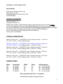
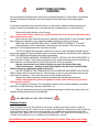
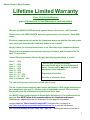
INSTALLATION AND
OPERATING INSTRUCTIONS
FOR
THE SHAVER
OUTDOOR WOOD and COAL
BURNING FURNACE
Manufactured by
Weld Rite Inc.
328 Hwy 62 West
Salem, Arkansas 72576
870-895-3104 or 3111
http://www.outdoor-wood-furnaces.com
The BEST Outdoor Wood Furnaces
On the Market!
Revised 1/10/2009
INTRODUCTION
Thank-You and congratulations on the purchase of your new Shaver Outdoor Wood (or Coal)
Burning Furnace! It represents the result of 36 years of Shaver experience and the input of
Shaver customers in the production of a top quality furnace.
With the purchase of this Shaver Furnace, you can now appreciate the high degree of
craftsmanship and reliability that are a result of every furnace being carefully hand-built.
Your choice shows the recognition you have for high quality products.
You are now a member of the large international family of Shaver customers, who have enjoyed
the elegance, efficiency and reliability of our furnaces for many years.
The Shaver Furnace was the first and is the leader in the Outside Wood Burning Furnace field.
We sell furnaces as far away as Canada, the UK, Ireland, the Ukraine and Spain!
We deem it important to provide you with this user's and maintenance manual: to allow you to
use your equipment under the best possible conditions and in the most optimal manner, and
furthermore to increase its operating life. We strongly advise you to read it twice, carefully
and keep it handy.
Again, Thank-You for purchasing the original Shaver Outdoor Wood Burning Furnace
THIS MANUAL INCLUDES IMPORTANT SAFETY INFORMATION.
Your new furnace should have the following:
(1) Owner’s manual complete with Installation and Hook-Up Instructions
(2) Warranty & Return Warranty Card (pages 6 – 8, 49)
(3) A large specially designed poker FREE - as a bonus! (Often shipped above the boiler in the
back of the furnace.)
Weld Rite Inc.
328 Hwy 62 West
Salem, Arkansas 72576
870-895-3104 or 3111
We are always here to help!
“When in Doubt – Make it Stout”
2
Table of Contents
General Information – Specifications ….……………..……...……….…………..…………………
SAFETY PRECAUTIONS ….………...………………………………………………………………
20-Year Limited Warranty ..………….………………………..………………………………………
Warranty Card ………………………………………..……………………..…………………………
Outdoor Wood Furnace Best Burn Practices ………….………………………..…………………..
Where should an Outside Wood Burning Furnace be located? ……….…………………………
Wood Recommendations and Burning Coal ...………….………………………..…………………
How does an outside furnace heat my home? …………….……………………..……………..…
How does the Shaver Furnace heat water for household use? ……………….….……………..
How do the Thermostat Controls work? …………………………..………………..……………….
Insulated Pex Pipe & Insulating Yourself .……………………………………………….……….…
Pex Pipe Connections - Back of furnace ………………….………………………...……………….
Concrete Pad …….………………..…………………………………………………………………...
Preparing Your Furnace ………………………..………………..……………………………………
Filling Furnace with Water and chemicals …………………….…………………………………...
Plumbing Parts Needed ……………………………………………………………………………….
Installing the Heat Exchanger in the Plenum or Ductwork ………………………………………...
Installing a Heat Exchanger that is Longer than the Plenum …………...………………………..
Heat Exchanger and transition pictures …………………………………………………………….
Bleeding a Heat Exchanger .………..…………………………....…………………….…………….
Insufficient Air Flow ………..……………………….……...……………………………...…………...
How to prevent the water from freezing …………..…………………………………………………
Connection of Power to Furnace ………………………………….…………………….…………….
Wiring your home thermostat ………………………………………………………….……………..
Hooking up the Hot Water Heater ………………………………..……..……………………………
Hot Water Heater Pump Pictures ……………………………………………………………………
Heat a Pool or Spa ………..………….……………………………………………….…..…………..
Hooking up the Outdoor Furnace to an Existing Boiler ………………..…………...………..…….
Boiler and Pool Heat Exchanger Pictures …………………………………………………………
Starting a Fire …………………………..………………………………………………………………
Fire is hard to start …………….………………..……..……………………………………….……...
Testing a new furnace ………………….…………..………………………………….……….……..
Maintenance …………………………………………………………………………………….………
Replacing a Hot Water Coil (in furnace) ……………………………………………..………………
Trouble-shooting ………………………………………………………………………...………….….
Poor water flow ………….………………………………………………………………………..…
Little or no heat ………….………………..…………………………………………………………
If the water is boiling …….….…………….………………………………………...………………
Steam escaping from door ………………………………………………………………………
Steam inside of furnace, dripping from roof, wet insulation ……………………………………..
Excessive water usage …………………………………………………………………………….
Heat Exchanger Cleaning Procedure …………..…….………………………………………………
Disclaimer ……………………………………………………………………………….……..............
Extra Warranty card to be mailed back to us …… ..…………...................................................
4
5
6
8
9
9/13
10
11
11/33
11
12
13
14
17
18
20
23
25
27
28
28
28/31
29
32
34
36
37
38
39
40
40
41
42
43
45
45
45
40/46
42
41
46
47
48
49
3
GENERAL INFORMATION
Specifications
Type of fuel – Wood and coal only
For outdoor use only
Electrical Rating 115 VAC/ 60 HZ / 1PH
15 AMP Breaker
Clearance to Combustibles
Top, Rear, Sides: 18”
Chimney Connector: 18”
Always use a double or triple-wall pipe when going through any kind of roof with at least
6” to 2 feet of clearance from any combustibles (depending on the type of flu pipe). Check
with the manufacturer for their recommendations! We suggest using Metalbestos® stove pipe
for the flue, which is insulated to prevent fires (available at ACE Hardware).
Front: 10 feet, with the door facing away from the structure.
Flooring: Non-Combustible
FURNACE DIMENSIONS
Shaver Pro Series 140 - 134,000 BTU and a 125 gallon water tank. 3,000 sq ft.*
45" x 48.5" x 90" tall - 1400 lb shipping weight
Shaver Pro Series 165* - 165,000 BTU and a 170 gallon water tank. 4,000 sq ft.*
45" x 54.5" x 90" tall - 1610 lb shipping weight 1745 with ½” firebox
Shaver Pro Series 250 - 240,000 BTU and a 230 gallon water tank. 5,500 sq ft.*
45" x 70.5" x 90" tall - 2000 lb shipping weight 2200 with ½” firebox
Shaver Pro Series 290 - 280,000 BTU and a 260 gallon water tank. 7000 sq ft.*
45" x 78.5" x 90" tall - 2300 lb shipping weight 2525 with ½” firebox
Shaver Pro Series 340 - 326,000 BTU and a 300 gallon water tank. 8,000 sq ft.*
45" x 88.5" x 90" tall - 2600 lb shipping weight 2875 with ½” firebox
FIREBOX SIZES
Model
Description
Width
Depth
Height (approx)
140
165
250
290
340
36” cylinder
36” cylinder
36” cylinder
36” cylinder
36” cylinder
36”
36”
36”
36”
36”
28”
34”
50”
58”
68”
26” + 10” for Ash Pan*
26” + 10” for Ash Pan
26” + 10” for Ash Pan
26” + 10” for Ash Pan
26” + 10” for Ash Pan
*Non-removable Ash “Pan” or receptacle
All specifications subject to change at any time.
4
SAFETY PRECAUTIONS
WARNING
Do not operate this equipment for other than its intended purpose nor other than in accordance
with the instructions contained in this manual and all other instructions accompanying the
furnace.
For furnaces covered by this instruction book, it is important to observe safety precautions to
protect yourself from possible injury. Among the many considerations, you are advised to:
•
•
•
•
•
•
•
•
•
•
•
•
•
•
Observe all safety stickers on the furnace.
This furnace must be wired by a qualified electrician in accordance with local and/or
National Electrical Codes.
Never use any type of petroleum product, petroleum based product, charcoal starter, lighter
fluid, lantern fuel, kerosene or any other flammable accelerant to start your furnace.
KEEP ALL SUCH LIQUIDS WELL AWAY FROM FIREPLACE WHEN IT IS IN USE.
Keep antifreeze, which is flammable, well away from the furnace. Only use non-toxic
antifreeze. Test antifreeze and other chemicals annually.
The use of treated wood (painted, treated, etc.) and any other salvaged material that can
emit noxious gases for the environment and is corrosive towards the components of the appliance
is NOT ALLOWED and eliminates the rights of guarantee.
DO NOT BURN GARBAGE, HOUSEHOLD WASTE, STRAW, HAY OR YARD WASTE. In
most areas this is illegal. The furnace is designed to burn seasoned cordwood and coal. Burning
other materials can reduce the life of the furnace and will void your warranty.
Always open the ash door (bottom) before you open the firebox door (top).
Open Loading door – pausing momentarily between the first latch and the safety
latch to allow any combustion gases to burn off.
DO NOT OPERATE THE FURNACE WITH THE DOOR OR ASH RECEPTACLE DOOR
OPEN. Always latch the doors securely. If the ash door is open for any extended period of time,
other than for cleaning - it will cause over-firing of the fireplace and boiling.
Always use proper care when installing, operating and maintaining the furnace.
Always wear protective gloves and glasses and be aware that hanging and loose
clothing can catch fire!
Do not modify the furnace. Do not substitute repairs that can be provided by your dealer,
distributor, or Manufacturing Company (Weld Rite, Inc).
Failure to heed these warning or any additional warnings on the furnace may result in an
accident causing personal injury and damage.
CALL BEFORE YOU DIG THAT TRENCH!
Disposal of ashes
OPEN THE ASH DOOR FOR THE DISPOSAL OF ASHES. ASHES SHOULD BE PLACED IN A METAL
CONTAINER WITH A TIGHT FITTING LID. THE CLOSED CONTAINER OF ASHES SHOULD BE PLACED ON
A NON-COMBUSTIBLE FLOOR OR ON THE GROUND. ALL COMBUSTIBLE MATERIALS SHOULD BE
DISPOSED OF BY BURIAL IN SOIL OR OTHERWISE DISPERSED, THEY SHOULD BE RETAINED IN THE
CLOSED CONTAINER UNTIL ALL CINDERS HAVE THOROUGHLY COOLED.
All installation and operation must follow Federal, Provincial, State and Local Codes
5
Shaver Outdoor Wood Furnace
Lifetime Limited Warranty
5 Year 100% On-Site Warranty!
plus a Lifetime and 30 Year Warranty on roof and siding!
We have a 5-YEAR ON-SITE warranty against leaks on the furnace - NOT prorated.
Plus we have a 20-YEAR ON-SITE warranty against leaks on the furnace - Parts AND
Labor.
Electrical components such as the fan, thermostat and pump and the door and grates
have a one-year manufacturer's warranty (labor is not covered).
We don't have you ship the furnace back to us, like some other companies demand.
We send a local professional repairman out to your furnace, and it's repaired on the
spot, if it ever leaks!
Years 6-20 are prorated as follows. We pay the following percentage or credit*:
Year 6 - 90%
Year 7 - 80%
Year 8 - 70%
Year 9 - 60%
Year 10 - 50%
Year 11 - 40%
Year 12 - 14 - 30%
Year 15 - 20 - 20%
Year 21 to forever - 10%
* We will give you the percentage
discount on the repair or off a replacement
boiler. Furnace will be repaired or replaced,
whichever is less expensive.
Shipping not included.
No cash or surrender value.
The cost of the service call is not covered after 5 years.
The life of your furnace depends upon proper maintenance. With proper maintenance
your furnace can give you 25 - 30 plus years of dependable service. We have many
that are 25 years old and they’re being built even better now!
You MUST submit a water sample to Wood Boiler Solutions LLC for professional lab
analysis. You MUST follow their recommendations for chemicals and brands.
Chemicals are added where the Hot Water coils is. See page 43 for pictures.
Just purchase the "Water Sample Analysis Kit" from their store, on page 2 at
http://www.diswebsites.com/woodboilersolutions/store.cfm or you can call them at
920-382-6498 Monday through Friday, 9am - 4pm CST - and they will send you out the kit.
6
WARRANTY CONTINUED
When the kit arrives, take a sample according to the easy to follow directions, package it up
and mail it back (postage not included). They will mail you back complete results with
interpretation and recommendations. (Allow 2 weeks for results)
The following tests are performed and interpreted for you: Nitrite, pH, Total Dissolved Solids,
Bio Test, Iron, Glycol Concentration/Level (if applicable) and Total Hardness. They look for
minerals that will eat up carbon steel.
This testing procedure will give you complete results and recommendations so you can be
assured your system is in top shape for the long haul.
We have Shaver Furnaces in service that are over 30 years old, with wood
siding (we used to make them that way) and they're still going strong!
Exclusions
1. Disasters, breakdown or faulty operation linked to:
• Inadequate relation between the nominal power of the equipment and the heat
requirements of the premises;
• a faulty installation or faulty connections;
• damage to the thermostat through overheating due to intensive use:
- the ash box door is left open;
- When the ventilation convection fan is left off with high fires.
• Failure to clean out ash!! Moisture combined with ash will eat through a furnace in
short order and is NOT covered under warranty
• an insufficient or excessive draft;
• incorrect use;
• burning non-compatible fuels, destructive and/or damp fuels (treated wood, hay, straw
etc...);
burning other than non-treated, non-painted wood or coal; Damage caused from burning
coal is not covered under the warranty – even on the coal series furnace.
• consumption exceeding the use limits;
• a lack of maintenance; not adding the recommended chemical, water treatment and rust
inhibitor.
• any modification, transformation inside the appliance;
• transport and installation.
2. Transport and packaging cost.
3. All costs not previously accepted by Weld Rite, Inc.
4. Costs and deterioration due to the non-use of the equipment.
5. The cost of any incidentals or consequential damage, including the loss of
anti-freeze and/or water treatment.
6. Warped Grates or door. Grates and doors always warp over time due to high heat.
7. The guarantee starts on the date of delivery. The invoice showing the delivery date is
the only document valid for the guarantee.
7
All warnings in this manual on Page 5 and elsewhere and all maintenance items on
Page 42 constitute part of this warranty.
8
Please fill in the following information and mail this copy by mail to:
Weld Rite, Inc., 328 Hwy 62 West, Salem, AR 72576
Your name and address:
________________________________________________________________
________________________________________________________________
Phone number(s): ________________________________________________
Shaver Model:
Date of Purchase:
___________________________
_____/_____/____
Serial Number: (Only applicable only if financed)
___________________________
Date of Installation and who installed (Proper self-installation, following the
instructions. will not void the warranty):
___________________________
Dealer Purchased from (if purchased from the factory, put Weld Rite, Inc.):
_________________________________________________________
Dealer Address:
________________________________________________________________
________________________________________________________________
Dealer Phone Number: ___________________________
Please keep this manual with all other important papers. The information in this manual is
necessary for the installation, operation and proper use of this furnace. If you should ever have a
problem or question please refer to this manual or have it available when you call your Shaver
dealer or Weld Rite, Inc. Phone: 870-895-3104 or 3111
A duplicate for mailing is at the end of this manual. Retain this completed copy for your records.
9
OUTDOOR FURNACE BEST BURN PRACTICES
1. Read and follow all operating instructions supplied by the manufacturer.
2. FUEL USED: You may burn any hardwood (or softwood), as well as pallets that have been split up
and coal but NEVER burn driftwood, painted, stained or pressure or/and chemically treated wood.
Never use the following: trash, plastics, gasoline, rubber, naphtha, household garbage, material
treated with petroleum products (particle board, railroad ties and pressure treated wood), leaves,
paper products, and cardboard. If you burn softwood, the wood will burn faster and you will have to
clean the creosote and chimney more often.
3. LOADING FUEL: For a more efficient burn, always add wood before the wood has burned out.
Most often it can be loaded in the morning and at night. Load coal before wood. See next page.
4. STARTERS: Do not use lighter fluids, naphtha, gasoline, or chemicals.
5. LOCATION: It is recommended that the furnace be located with due consideration to the
prevailing wind direction. Chimney height can be easily extended with 5.5” Stovepipe. You can get
downdrafts if the furnace is too close to a building. See Page 13 for additional information.
•
•
•
We recommend a distance of at least 100 feet if prevailing winds blow towards any other
residence not served by the furnace, it is recommended that the stack be at least 2 feet higher than
the eave line of that residence.
If located more than 100 feet but no more than 150 feet to any residence, it is recommended that
the stack be at least 50% of the eave line of that residence, plus an additional 2 feet.
If located more than 150 feet but no more than 200 feet to any residence, it is recommended that
the stack be at least 25% of the height of the eave line of that residence, plus an additional 2 feet.
Chimney height relative to nearest downwind neighbor
The chimney can easily be extended with our chimney adaptor (optional) or 5.5” stove pipe,
to any height necessary, with zero adverse affect on performance. In fact, it may even draft
better. Always use at least a double-wall pipe when going through any kind of roof! The
chimney should extend at least 2 feet higher than any portion of a building within a horizontal
distance of 10 feet. You can get downdrafts if the furnace is too close to a building.
6. Always remember to comply with all applicable federal, state and local codes and
laws.
10
Wood Recommendations
Burn only cordwood that has been seasoned for 12-18 months. Burning unseasoned wood is
wasteful and inefficient, using much of the combustion energy to boil off the excess moisture.
It also puts a lot of moisture into the ash “pan” which makes it corrosive. The wood can be
split to aid in seasoning if it’s real wet and should be approx. 25% moisture content by
weight. However, whole rounds burn longer and are cheaper but will have to be dried
longer.
The following are general guidelines for wood selection:
• Hardwoods burn better than softwoods (mix them if you need to burn softwood).
• Larger pieces (whole rounds) are best and burn better and longer than small pieces.
• 25% moisture content is optimum. Drier is ALWAYS better!
Higher moisture content wastes energy boiling off water. Wood with a lot of moisture can
cause more smoke than the chimney can dispose of. It also puts a lot of moisture into the
ash “pan”, which makes an extremely corrosive mixture. Ash corrosion is NOT covered
by the warranty.
Lower moisture content (very dry, old wood) burns rapidly and inefficiently.
Burning Coal
We recommend that you burn a coal and wood mixture. A nice bed of coal (about 8-10
shovels) up to the bottom edge of the door, heaping it in the middle with wood on top, burns
best according to our customers.
Keep the ash receptacle and firebox clean, as coal is very corrosive. Damage from
burning coal is not covered under the warranty. You may want to add firebrick, placing
it on the floor of the furnace or/and elsewhere.
This furnace is now available now with an optional adjustable shaker grate, for burning coal –
a FIRST in the industry!!
11
THE SHAVER OUTDOOR WOODBURNING FURNACE
How does an outdoor furnace heat my home?
The Shaver outdoor wood furnace is designed to save the most energy and provide the most
comfortable heating available. It heats your home by heating a firebox surrounded by a steel tank
filled with water. The furnace is basically a safe non-pressurized boiler with an atmospheric vent.
This hot water is then circulated through underground hot water pipes (Pex Pipe) to a water coil
(heat exchanger) installed inside your existing central duct system.
If you have a boiler, a water-to-water heat exchanger is used. The Shaver furnace can be
connected to virtually any existing pressurized or non-pressurized boiler, Hydronic or radiant
heating system that operates at 180 degrees or less. It will not work with steam systems.
A typical water-to-air heat exchanger - much like a small
radiator or heater core in a car, is installed in your ductwork.
When air blows through it, heat is extracted and hot air blows
out of your vents. You can also use hydronic or radiant heat
utilizing Pex Pipe under he floors or in a concrete floors or by
using radiators or baseboard hydronic heaters.
How does the SHAVER furnace heat water for household use?
Water is circulated directly between your hot water heater and the outdoor furnace, through the
built in heat exchanger in our furnace. The water going back to your hot water heater is
preheated by a coil in the outdoor furnace. The only energy required is maintaining the hot water
temperature in the outdoor furnace. An extra circulating pump is needed. Page 35
A stainless steel shell and tube heat exchanger should be used for heating pools and spas. The
chlorine will tear up a brazed plate heat exchanger. See page 37
How do the Thermostat Controls work?
The only visible addition to the heating system inside your home is a 2nd thermostat, which is
located near the existing thermostat, if possible. The thermostat is installed (see page 32) so that
it turns the turns the blower on inside your existing furnace to force air across the hot water coil
(heat exchanger). This forces hot air into your central duct system. The original wall thermostat
turns on your original furnace, if the outside wood furnace is not in operation. Your existing
furnace will automatically take over to maintain your household temperature.
When the indoor furnace fan powers up, it sends power to the circulating pump, in the outdoor
furnace, to circulate the hot water through the heat exchanger.
If you have an existing boiler, the pumps are controlled by the thermostat. When the pump
comes on (assuming one main pump), power is sent to the outdoor furnace’s pump so that both
pumps run simultaneously.
Simply wire the outdoor furnace’s circulating pump to the power wire of the indoor pump (if using
a single pump). If you are using a controller for multiple pumps and zones but don’t have one
main pump, you will need to use your controller to turn on the outside pump anytime a pump in
12
your house turns on. See your controller manual or consult an expert in this area. You can also
leave the outdoor pump on 24/7, since it only uses 80 watts of power – less than a 100W bulb.
The outside furnace has a hot water thermostat that senses the water temperature of the unit. If
the water is not as hot as the thermostat setting, the combustion air blower is automatically
turned on (building a hotter fire by feeding oxygen to the base of the fire) and remains on until the
desired (set) temperature is attained.
Insulated Pex Pipe
We highly recommend that all Pex Pipe be insulated. You will burn less wood because there will
be virtually no heat loss through the Pex pipe. ALWAYS bury it below the frost line for less heat
loss and to avoid freezing. The ground temperature below the frost line will be 50-55F or more.
You can purchase insulated pipe in 4” black drain pipe with
two 1” Pex pipes and simply lay it in the trench, hassle–free.
You can also get premium, insulated pipe with 4 Pex Pipes
inside a 5” pipe (Two x 1” and Two x ¾” in) for approx.
$14 a foot. The 5” pipe has 50% more insulation than the
4” pipe and it has an R value of 14.
With a little effort, you can save a lot of money by insulating it yourself. Try to keep the Pex
pipe underground as it enters the house. A 4” or 6” hole in concrete block, is easily made for
the PVC pipe. If it has to come above ground, go through the sill plate or attic, it MUST be
well insulated, as well as if running through an attic or crawl space or any non-heated area.
The insulation of choice is Solarguard™ (or Microfoil or Reflextix if Solarguard is unavailable).
You can find out where to purchase Solarguard locally (close to you) by calling 1-800-231-6200,
or you can purchase it from us. One roll 4’ x 50’ will do approx. 80 linear feet of Pex pipe.
http://www.silvercote.com/solarguard_reflective_insulation.php
It is a state-of-the-art insulation that is only ¼” thick, yet yields an R value just shy of R12 – with
one layer. It deals with the following modes of heat transfer: CONDUCTION, CONVECTION or
RADIATION. Fiberglass insulation alone only addresses the conduction and convection modes of
heat transfer. Solarguard uses a fiberglass core to slow heat transfer through conduction and
convection but also has a highly reflective foil backer film to address the RADIATION mode of
heat transfer. 50-93% of heat loss is through radiation.
Simply cut the rolls into strips, for easy wrapping. Use 6” PVC pipe for easier pulling through of 4
runs of insulated Pex and the wire. Be sure to wrap it inside the back of the furnace as well.
Cut a 4’ x 8’ sheet of blue Styrofoam into 2” strips, 4 feet long. This
will give you 24 pieces, 4 feet long – sufficient for 96 feet of pipe.
Place the Styrofoam strips between the hot and cold Pex pipes. Tie it
all together with plastic wire ties.
Wrap loosely with Solarguard™, to create an air barrier, overlapping
as you go. The air gap will add extra R value. Tie it all with wire ties
again, using tape the seal the ends, with a wire tie over the tape to
hold it secure, so that when it dries out it doesn’t fall off.
13
Pex Pipe Routing
Single zone setup
with one pump
1. Goes to house heat exchanger
2. Return from house heat exchanger
3. Power to pump, thermostat and
blower
4. Inlet to potable water coil (not seen inside of furnace, in water jacket)
5. Outlet from potable water coil
6. To manual fill valve on front of
furnace
7. Water supply to furnace from manual
fill valve
8. Optional outdoor hot water supply for
a faucet or steam cleaner hookup.
9. Drain
10. Blower/fan to feed oxygen to fire
The furnace shown is an older single zone
plus the hot water coil. All furnaces come
with another hookup now for another
building, at no cost (not shown). 2nd Pump
not included.
Do not wire as shown. This is not to code
and is shown this way for simplicity only.
Location of Furnace
11. Armstrong Astro-30 Pump, one
included (to circulate water)
12. Thermostat (for blower)
#1 and 2 with arrow shows direction of
water flow for built-in hot water coil in
furnace
Recent research has shown that it’s
better to have the pump at the bottom
and the return line where the pump is
shown now!
SOME STATES HAVE THEIR OWN LAWS!
The outdoor furnace should be located at least 10 feet from your home (according to most
insurance companies), with the door facing away from the house, so that all fire danger is
removed from your home. We recommend 30 feet or more. The furnace may be installed as
much as 100-120 feet away with the standard pump (or up to 300’ with a bigger pump) and
14
still heat your house and hot water easily. The chimney should extend at least 2 feet higher
than any portion of a building within a horizontal distance of 100 feet. (See page 9)
If the furnace is located more than 100 feet away, you may experience some heat loss in the
water going to your heat exchanger (and water heater) – about 2 degrees/100 feet of wellinsulated Pex pipe. A larger pump than the one supplied is needed for distances over 120
feet or/and any rise in elevation over 8 feet. For extreme distances (200 ft plus) we
recommend that your pump stays on all the time so there is no delay in getting heat because
there is always hot water available at the heat exchanger when the furnace fan comes on.
Locate the outdoor wood furnace where it will be convenient for refueling and wood storage.
All water and power lines are installed underground between the house and the outside wood
furnace in a 4” or 6”PVC pipe that is ALWAYS buried below the frost line.
The furnace should be installed on a 4” thick concrete pad.
A) It is recommended that the furnace be located with due consideration to any
neighboring residences and to the prevailing wind direction.
B) Do not locate an Outdoor Wood Burning Appliance within 100 ft of a residence
not served by the furnace. Follow local and state laws concerning setbacks.
Please be considerate of neighboring residences, properties, parks, etc.
C) Review the recommended stack heights on page 9.
D) Do not locate near any combustible materials, gasoline or other flammable
liquids or gases.
E) Locate away from dry grassy areas, dry leaves, brush and trees.
F) Place far enough away from any building to minimize fire danger.
G) Check with your insurance company and local codes or ordinances.
H) Do not install in an area where nearby structures or trees might cause
downdrafts or fires.
I) Typically, Outdoor Wood Burning Furnaces are located 40 to 100 ft down wind
from the served structure.
J) Transfer lines in excess of 120 ft may require a larger size pump than the
one provided with the furnace, especially if there is any head (or incline).
K) Locate the furnace to allow easy access to wood supply.
L) To aid in smoke dispersal, extra chimney lengths may be required depending on
the distance to surrounding structures. See page 9 for additional guidance.
M) The furnace requires 115 V, 15 Amp electrical service to operate.
Failure to keep the Shaver Furnace area clear and free of
combustible materials, gasoline and other flammable liquids and
vapors can result in severe personal injury, death or substantial
property damage.
CONCRETE PAD: The furnace should be installed on a concrete pad with the rear of
the furnace 2-3 inches from end of the pad, so that the pipe comes up in the space
provided between the back door and the rear of the water jacket, where the pump is.
The space between the inside rear of the furnace and the door will allow space for a 4
or 6 inch water- tight PVC pipe with the plumbing and electrical lines, to run directly into
15
the ground. We put a large full-size door on the back that will allow you easy access for
the connection of the plumbing and electrical lines.
We recommend the pad to be 48” wide and 82” long, minimum. If you add extra length,
it will allow ample concrete in front of the furnace to stand, for loading wood and
removing ashes. Larger models than the 165 need to have a longer pad.
Shaver Pro Series 140 - 48" x 114" Suggested pad size
Shaver Pro Series 165* - 48" x 120" Suggested pad size
Shaver Pro Series 250 - 48" x 136" Suggested pad size
Shaver Pro Series 290 - 48" x 144" Suggested pad size
Shaver Pro Series 340 - 48" x 154" Suggested pad size
Placement of pipe
through the pad and
into the ground - shown
without the rear door
installed,
Recent research
has shown that it
can be better to
have the pump at
the bottom and the
return line where the
pump is shown now!
The PVC pipe is always buried below the frost line and most jurisdictions require a
18-24” minimum depth for the electrical wire, sometimes separated from Pex by 18”.
See the illustration below for the recommended pad size and pipe placement for a 165
furnace. Other suggested pad sizes shown above.
16
Have insulation ready to put UNDER the furnace on the pad, before delivery. After placing
your new Shaver Furnace on the concrete pad (we normally put it on the pad for you if we
deliver it), you are ready to continue the installation process.
The piping can go in any direction. It just needs to be in the proper spot above the concrete pad.
17
PREPARING YOUR FURNACE
1. Simply open the large rear door to gain access to the rear of the furnace, to
make plumbing and electrical connections.
2. Open the protective cover on the side of the blower. Simply swing it open so the
inlet is exposed ¼ of the way. Door is shown swung open below.
The fire should be blazing when the fan is on. It
should be just smoldering if the fan is off.
Quickly crack open the firebox door to see what the
fire is doing. (Leaving the door open any length of
time will give you a blazing fire.)
If you have too hot a fire with the fan off, close the
cover on the side of the fan a little more. The water
should never be boiling. If it is, the cover is open
too far or there is a downdraft problem.
3. The plumbing and electrical lines for your furnace must be installed underground
in a watertight (glued) 4” or 6” PVC pipe OR use pre-insulated pipe.
HOWEVER, some building codes require that the electrical wire be run 18”
away from the Pex pipe. Be sure to check YOUR LOCAL BUILDING CODES!
The water lines must be buried below the frost line to prevent freezing. The depth
of the trench varies in different regions of the country. Be completely sure about
the correct depth before the PVC pipe and Pex Pipes (or pre-insulated pipe) are
installed underground. Call your local building inspector’s office for that
information.
4. A trench must be dug wide enough to accommodate the pipe that you choose. All
plumbing and electrical lines are usually run inside the watertight PVC pipe.
5. HINT: Remember to run 2 small ropes or twine through it as well to facilitate
pulling anything else through that may be added or changed in the future!
6. If more than one location is to be heated, then additional PVC with Pex pipe,
must be installed underground to that location.
7. This pipe will run from the rear of the furnace to the location to be heated. Inside
the watertight pipe are the water lines and electrical supply wire (12/3 UF
w/ground).
Some building codes require that the electrical wire be run
separately in the trench, 18” away from the Pex pipe (not in the PVC pipe).
18
The listing below describes each water line and their function.
1. One water supply line to heat exchanger - placed into existing heating system. This
one is attached at the circulating pump. All of these must be 1” pipe.
2. One water return line from heat exchanger. This line is attached at the nipple at the
bottom of the furnace, to carry cool water back into the water jacket.
3. One ¾” water supply line to indoor plumbing for filling the furnace.
4. One #12/3 W/Ground UF underground Romex wire. The extra insulated wire supplies
power to your pump, from your furnace fan in your existing furnace (or boiler pump),
instead of running a thermostat wire and installing a relay (more to go wrong).
OR
If you are heating your hot water, simply run two ¾” water lines to your water heater.
One of those will supply the water to fill the furnace, so a separate Pex pipe isn’t
needed. You will have a total of 4 (four) Pex lines running to your house in this scenario.
If more than one location is to be heated, a second 4” watertight pipe (or insulated Pex
pipe) will need to be installed underground for the water lines and the 12/3 power wire
from the second location. The 2nd location is wired as the first. No thermostat wire is
normally needed. Locate this pipe at the opposite side of the outdoor furnace per
diagram on page 16, unless it’s running in the same direction as the first. In that case
both pipes can be on one side or in the middle, as needed.
HINT: Label the water lines before burying the pipe and lines
Filling furnace with water and chemicals
Once your Pex Pipe is hooked up, simply
turn on the manual fill valve at the front
of the furnace and allow it to fill until
water runs out the overflow (Shown left
of red corner piece). After starting the
pump and bleeding the heat exchanger,
top off the water again. Be sure to open
the valve at least once a week during
heating season to keep the furnace
topped off. Failure to do so may result in
overheating and circulating pump failure.
DO NOT block off the overflow tube!
To add chemicals to your water you can remove the plate (shown below) that normally
covers the hot water coil in the back - above the thermostat and pump. Or use a funnel
and hose at the overflow pipe. See below and Page 43 for more pictures.
19
Plate ^
You can also use an elbow and extension at the 2nd outlet (if not being used) to fill using
a funnel. Keep it capped when not using for chemicals.
Alternatively, you can use a funnel and hose on the overflow tube. DO NOT block off
the overflow tube permanently!
20
Plumbing Parts Needed
You can get a complete install kit with all the fittings and three shut-off valves.
A. The pump needs a 1” quest-fitting adapter or SharkBite® fitting, to screw into a
flange that is supplied and already mounted to the pump. The flange has a female NPT
thread. See the picture below to help visualize this. It is the brass fitting on the bottom
of the pump. It is shown with a Quest or Pex pipe compression fitting already screwed
onto it.
B. The Quest fittings or poly pipe fittings can be purchased locally at any good plumbing
store. SharkBite® fittings are now the connector of choice, receiving rave reviews from
our customers! These are also available from Alternative Heating and Supplies in CT.
You need 1” Pex Pipe for the main pumps to the heat exchanger.
The Pex Pipe connected at the bottom of the pump runs to the house and normally runs
to your heat exchanger (water-to-air or water-to-water).
This will also be your supply line if you have a Hydronic or radiant heating system. A
brazed-plate heat exchanger is recommended between the two systems. See end of
this section for more information on hooking up a brazed-plate heat exchanger.
You need ¾” Pex Pipe for the hot water heater, which is commonly known as 7/8” Poly
Pipe since the OUTSIDE diameter is 7/8”.
SharkBite™ fittings are
HIGHLY recommended
for installing the Pex
pipe.
Customers rave about
them and their ease of
use!
No leaks, the first time –
using simple push-on
fittings.
No special tools are
needed.
Compression fittings are
shown to left.
21
C. The pump comes already mounted directly to the furnace without a shut-off valve.
However, it is a good idea to install a shut-off valve above the pump (as pictured below)
so that if the pump ever has to be changed, the water supply can be shut off so water
doesn’t flow out of the furnace during the repair or pump replacement.
When you have
several large
pumps, it’s better
to have the pumps
at the bottom and
the return line
where the pump is
shown now!
Simply reverse
what is shown and
you will have a
better setup!
Simply add a valve and a threaded pipe (threaded on both ends), as shown.
D. It is also a good idea to put TWO shut-off valves on the return lines. This helps bleed
the system of air and is a big help when troubleshooting. (Shown on next page.)
ALL of these parts are available as an “installation kit” (saving a lot of running around)..
See the picture on next page. Note that two different types of shutoff valves are used,
but they can be the same. Personally, I would reverse them to make bleeding easier.
22
Adding Shut-off Valves for Testing a New furnace & for Trouble-shooting down the road
(Note PVC Pipe at bottom right (above), is installed in the concrete for future addition of heat to the
garage, shop or other building)
Adding two shut-off valves on the return lines is done so that if there is a potential
problem with a stopped up heat exchanger or bad pump, it can be diagnosed easily by
the owner, without the need for a service call.
See TESTING for more information.
Adding two shut-off valves (Available as a kit):
1. You will need a shut-off valve with 1” Poly pipe connectors on both ends.
2. You will need a 1” Poly pipe connectors and adapter to connect the Pex Pipe to the
brass valve on the right. .
3. You will need a short piece of pipe with 1” NPT threads on both end to connect the
valve to the furnace.
Sealing off the Plate on top of the Hot Water Coil
This is where you add your chemicals – preferably before sealing it off.
Seal off the black plate (with the handle) that covers the hot
water coil, with silicone all the way around, after all Pex pipe
has been hooked up. See page 43 for pictures.
23
Installing the Heat Exchanger in the Plenum or Ductwork
If you have Air Conditioning, the heat exchanger must be installed between the furnace
and the evaporator coil. Failure to do so may result in freezing of the heat exchanger. If
you can’t place the heat exchanger between the furnace and the evaporator coil, you
must drain the heat exchanger annually before using the A/C.
The heat exchanger must be installed so that it is airtight. No air must be able to flow
around it or out of the ductwork. Use adhesive backed foam tape (used for insulating
doors and windows) around the water coil. Use foil tape to seal off the heat exchanger
and the hole you make, or consult a local HVAC installer or technician.
Make sure the fittings are easy to get to once it’s installed. Ideally, there should be no
splices in any water lines! If you have to splice two lines together, use SharkBite®
fittings. The IN fitting should be at the bottom of the lowest point (bottom) unless
installed horizontally. In that case, see if the heat exchanger is marked in/out.
You should be able to find a heat exchanger to fit most popular sizes of plenums. If you
can’t, you must have your ductwork modified to accept the heat exchanger. This is best
left to a professional, unless your ductwork is made up of fiber board. In all cases wear
protective gear, gloves and glasses and a mask. Edges can be SHARP!
Measure the width of the heat exchanger (Dimension A in next diagram). Measure the
thickness of the heat exchanger (Dimension C).
Start by cutting a hole in the side of your ductwork the thickness of the heat exchanger
(Dimension C) and the full length of the ductwork (usually Dimension A).
WARNING! Metal edges are very sharp! Where protective
gloves and use caution!
24
Slide the heat exchanger into the hole for a test fit. Ideally the tubes (D and E) should
stick out of the plenum [see diagram on previous page]. The header and tubes (F) can
stick out of the plenum as well, if necessary.
As long as the whole coil surface (B) is in the plenum, you should be good even if a little
more of the header (F and even G) sticks out.
While test fitting it, try to determine how much tape is needed around it. A different
amount (thickness) may be needed on different sides. You can purchase different
thicknesses of tape so that it will fit and seal properly.
Place foam tape around the outside of the heat exchanger to seal it off so that it fits tight
and air can’t blow by it.
The heat exchanger needs to be installed so it won’t move around. The easiest way is
to fabricate some pieces of metal into an ‘L’ shape, approx. the length of the heat
exchanger like shown below.
This is what the braces will look like. Very simple. Rivet or screw into place.
25
Install the braces as shown above. Simply put them in place, the proper width apart
(Dimension C). Drill through the duct work and your newly made ‘L’ pieces and pop rivet
or screw them into place. You will need four pieces, two each on the top and bottom.
Slide the heat exchanger carefully into the plenum to check the fit again. If all looks
good, you can seal off the ends of the heat exchanger and the hole you made in the
plenum with foil tape made for ductwork. Input lines should be at the bottom, unless
otherwise marked.
Installing a Heat Exchanger that is Longer than the Plenum
You can install a heat exchanger in a plenum that is smaller than the length of the heat
exchanger, as follows. Cut the lines at the top and bottom of the plenum, usually 4
inches long (the width of the heat exchanger).
Cut another line vertically, between the other two cuts, right in the middle as shown.
26
Slide the heat exchanger through the front hole to the back hole. So that it protrudes
front and back.
Ideally the core of the heat exchanger will be entirely within the plenum. (Item B)
Crimp the sheet metal to the edge of the heat exchanger. This is item G in the diagram
above (Page 23). Using channel-lock pliers to crimp it, it makes a very nice professional
looking installation. Input lines should be at the bottom inlet unless otherwise marked.
This not only forms a virtually airtight seal, but it also supports the heat exchanger as
well.
27
A transition was built
here so that a larger
heat exchanger could
be used with smaller
ductwork.
A customer’s photo of
his heat exchanger
installation.
28
Bleeding a Heat Exchanger
With the pump running (turn the thermostat up to 90 F so that the pump comes on),
simply close the brass valve on the return line quickly, holding it for 3-4 seconds. Then
open the valve. Repeat the procedure at least 4 times.
If you’re unsure if all the air is getting out, you can separate the 2 valves (shown on
previous page) at the Pex Pipe between them, after turning off both valves so that water
won’t drain out.
Insert the left plastic valve and pipe in a 5-gallon bucket. Open the valve. Then simply
close the plastic valve on the return line quickly, holding it for 3-4 seconds. Then open
the valve. Repeat the procedure 4 times. That way you can see if bubbles are coming
out of the line.
Insufficient Air Flow through Plenum
You can attain up to 42% higher BTU outputs with higher CFM of air flow. If you need
more airflow, the pulleys (if used) can usually be changed on the fan and/or motor to
give a higher fan speed. If you can’t get enough heat, a slow fan may be an issue
Many furnaces have 2 or 3 speeds or variable speed fans, utilizing the high speed for
A/C, which can beneficial here. Please consult a furnace specialist about this.
How to prevent the water from freezing
As long as there is a fire, the water won’t freeze in the outdoor furnace.
The pipes that are underground won’t freeze it they are below the frost line, as the
ground temperature is 50 degree or more.
WIRING: A switch can be added to turn off the fan
before loading. This will prevent smoke from blowin
your face.
An example is shown to left.
See instructions on Pages 30 or 31
A switch can be added to the pump as well,
in case you want to have it run 24/7 to
prevent freezing, while you are away. Or it can be
wired without the third (red) wire, to run 24/7.
Running water won’t readily freeze and it will pick
up heat from in the house to keep the water warm.
29
Connection of Power to Furnace
WARNING!
Do not touch the
terminals or wires on
the thermostat – THEY
ARE HOT AND
DANGEROUS!!
ALWAYS cover the
thermostat with a
solid receptacle/box
cover (Not shown
here) or a piece of
Plexiglas, as shown
below.
Notch at bottom for
wires, if necessary.
Use silicone or
screws to attach
cover plate to furnace.
This furnace must be wired by a qualified electrician
in accordance with the National Local and/or State Electrical Code.
30
There are three insulated wires in a 12/3 wire; red, black and white plus an
uninsulated ground wire.
Either terminal on the pump can be connected to the black or white wire.
White is common and also goes to fan/blower
Black wire from the pump runs to house, to fan inside existing furnace.
Red (from 110V source) goes to top terminal on thermostat
Ground (Bare copper wire) is attached to furnace frame and to the green
ground screw on both the pump and fan.
Running Pump 24/7
You can also wire up the
pump to run 24/7, instead
of on demand as shown.
In this case, you only
need a 12/2 wire, with
ground.
Simply run the hot wire to
the pump and to the
thermostat.
Common goes to the
other terminal on the
pump and to the fan.
Ground goes to boiler
frame.
Bottom terminal on thermostat goes to fan. Run a new single piece of wire between
thermostat and fan. (Shown here and in diagram below as an individual black wire).
FAN SWITCH: You can utilize a standard outdoor light switch in this line, to turn the
fan off while refueling the furnace. Simply wire it in the power line to the thermostat
or between the thermostat and fan, using an approved outdoor electrical box and
cover, to code. See page 28 for picture. A 3-way switch could be used with a reminder
light to let you know that the fan is off.
This furnace must be wired by a qualified electrician
in accordance with the National or/and County/State Electrical Code.
31
To add a switch for the
pump, so that it will run
constantly when you are
away, simply wire a
switch from the red (hot)
wire to the same terminal
that the black wire goes to
on the pump.
IMPORTANT! You will
also need to put a switch
on the black wire going to
the pump, to interrupt that
circuit so that when you
power up the pump (24/7)
it doesn’t cause the
furnace fan to run all the
time.
A 3-way switch would
probably work well here.
~~~~~~~~~~~~
The fan switch is wired to
the red wire that powers
up the thermostat for the
fan. Use an outdoor box if
mounting on the outside.
Wiring running to house
12/3 with Ground runs from inside house.
Red goes to 110V 15 Amp circuit breaker in house.
White is common (to circuit breaker box - common connections).
Ground wire is grounded in circuit breaker box and to the furnace frame.
Black goes to fan on existing furnace so that when fan comes on, power goes to
the pump at the same time. Power comes from fan power source - ONLY if inside
fan is 110V AND a single speed fan!
Consult a local heating contractor if you’re not sure about this part or if you are
dealing with an indoor fan (in your furnace) that is 220V.
32
Wiring up your house thermostat
These instructions are for a forced air furnace, with a single-speed fan. If you have other
than a single-speed fan, a boiler or are unsure about anything, you will need to consult
an HVAC technician.
Most existing thermostats have a fan switch that you can set to ON or AUTO. Simply
remove the thermostat cover and you will see a wire running to that switch, usually
marked as terminal G.
Disconnect the wire that runs to the G terminal on your existing thermostat.
Purchase a simple, 2-wire thermostat (a simple ON/OFF switch). Usually less than $15.
If you have a simple 2-wire thermostat, just use those 2 wires to connect to Terminal G
and the wire you just removed.
If you are using a thermostat with more than 2 wires, find the two wires that run to the
mercury switch shown below (or bi-metal switch or thermistor on a digital thermostat)
that make a connection when you turn the thermostat up. Those 2 wires are wired into
the fan switch wire(s) above at to Terminal G and the wire you just removed.
on the existing thermostat.
(The two wires are shown below (next page), as tan and blue on a 3 terminal mercury
switch)
Never assume that a wire color (or letter code) is correct for the function
it should perform; check it out first
Assemble the new thermostat on the wall and turn the fan switch on the existing
thermostat to ON. That’s it! You’re done!
33
Mercury Switch
Top and Bottom wires in the switch are typically used.
2-wire bi-metal thermostat
The two wires you need to connect are at 3 and 5 in this example of a 2-wire bi-metal
thermostat. They are wired to the G Terminal on the existing thermostat and to the wire
that went to the G terminal, that you removed.
34
Hooking up the Hot Water Heater
With an electric hot water heater, we recommend that you unscrew the pop-up
valve and replace it with a ‘T’ fitting (using Teflon or plumbers tape). Screw the
pop-up valve back on one side of the T and mount the circulating pump on the
other side of the T. Attach the Pex pipe to the pump (outgoing cool water).
Remove the drain and do the same, putting in a T with the drain screwing back in
on one side and the Pex Pipe connector (incoming heated water) on the other.
Remove the lower access plate on the hot water heater. Mount a hot water heater
thermostat on the tank with silicone around the outside edge - above, below or
beside the existing thermostat, at the bottom element. It’s about $8 at your local
hardware store. Smear the bottom of the thermostat with dielectric grease
(available at auto parts stores) before installing it. This facilitates better heat
transfer to the thermostat. Wire it so that 110V is on one terminal and the pump on
the other, just like a light switch. Common and ground wires go to the pump.
You just saved $200 for a side-arm heat exchanger! You can still use the heater as
normal in the summer and as a backup. Just turn your Hot Water heater circuit
breaker off during the winter or turn the thermostat down lower, than the one you
just installed. Turn the breaker back on in the summer and turn up thermostat.
NOTE: The Hot Water coils are submerged in water, in the tank of the outdoor furnace.
35
Alternatively, you can run the incoming (hot) Pex pipe to a brazed plate heat exchanger
for your hot water heater – before running to your heat exchanger for your furnace. It is
usually about $175. In this case, you would only need 3 Pex lines running to your house,
which may save a little, if the furnace is going to be a long distance away. The downside
is that your pump on the furnace would have to run continuously (24/7), instead of cycling
on and off as needed. They don't use a lot of electricity (about 80 watts) but it is increased
wear and tear. Eliminating the built-in water coil reduces the cost of the furnace by $75.
Our system is a LOT better because you have accurate temperature control. You don’t
end up with scalding water as is possible with the external plate HE or side-arm.
Gas Hot Water Heater
For a gas heater, there is usually a plate than can be removed to gain access to the
tank itself (or cut an access hole). Simply mount the thermostat on the tank and
follow the other instructions for water hookup above.
36
Customer supplied photograph: Make sure using a single wire is to code in your area.
37
Hooking up a Pool or Spa
A heat exchanger should be used to transfer heat from the outdoor wood furnace to the
pool or spa. You don’t want old dirty furnace water mixing with nice clean pool water!
Never use a brazed plate heat exchanger for a pool as the chlorine will destroy it in
short order. ALWAYS use a Stainless Steel shell and tube heat exchanger for this
purpose.
If the spa isn’t too big and you are NEVER going to use the built-in domestic hot water
heat exchanger to heat your hot water, you can utilize that for your spa or hot tub.
We have tried many different ways of hooking up pools with different systems;
thermostats, etc., where the pump goes off and on to control the water temperature.
The main problem is that when no heat is being extracted out of the furnace, the water
can boil. It is best to utilize a system whereby the pump runs all of the time so that the
water can’t just sit stagnant in the furnace, overheat and boil.
The thermostat is connected so that it controls a 3-way valve. When the water needs to
be heated up, the circulating water is routed to the heat exchanger. When the water
reaches a preset temperature, the 3-way valve bypasses the heat exchanger and sends
the water back to the outdoor furnace, keeping the water circulating. This system works
the best. A kit is available with complete instructions and every bit and piece needed
(including wiring for the controller), to make the installation super easy! Diagram by
Alternative Heating & Supplies.
38
Hooking up the Outdoor Furnace to an Existing Boiler
Again, we need to use a heat exchanger to transfer heat from the outdoor furnace to the
boiler or hydronic system so that the two systems remain isolated from each other. A
water-to-water plate heat exchanger is used in this type of system. No thermostat is
normally needed since we trick the boiler into thinking no heat was extracted!
The hookup is very similar to that shown above and a complete kit is available.
The 2 systems are totally isolated from each other so that the existing hydronic system
(usually pressurized) remains undisturbed and functions exactly as it did before. All
pumps and controls remain the same. The system’s return water goes through the heat
exchanger (on the right) and gets reheated before entering the existing boiler. This
tricks the boiler into thinking that no heat was extracted and it will not turn on.
The water circulates from the outdoor furnace, to the heat exchanger on the left side
(red line), out the top of the heat exchanger and back to the return (blue line) on the
outdoor furnace. Water that circulates through the furnace is never circulated through
the home’s hydronic system – or visa versa.
The 3-way valve (shown above) is not needed. Strainers are optional. The pump shown
is an existing pump (if used).
39
Set the existing boiler water thermostat lower than the temperature of the outdoor boiler.
Plate exchanger
Stainless Steel Shell and Tube Heat Exchanger for pool or spa
40
Starting a Fire
Use small pieces of split kindling together with crumbled newspaper or cardboard,
adding larger pieces as the flame grows. Remember: The smaller the better; the drier
the better.
If it is difficult to start the fire the reasons could be:
Not enough air: Make sure that fan is on or open the ash door (approx. 1 cm gap).
Bad/wet kindling: Use small pieces of split kindling together with crumbled newspaper
or cardboard, and add larger pieces. Remember: The smaller and drier the better.
Down draft/cold chimney: Heat up the chimney by twisting some newspaper into a
torch and hold it up into the stove until the draft is reversed.
Boiling water:
1. Draft cover for fan in back of the furnace is open too far.
2. A defective or loose thermostat could also be the culprit.
3. Try reversing input and output, by putting pump at bottom of furnace.
Be sure that the thermostat in the rear of the furnace is secure and up against the body
of the boiler. Dielectric grease (available from an automotive store) applied to the back
of the thermostat, can help in heat transfer. Using an aftermarket digital thermostat is an
alternative and will have a sensor that can be placed in the water possible getting more
accurate readings. This goes against our philosophy of keeping it simple and
inexpensive, but some people do this upgrade ($100 vs. $5),
If the fan stays on all of the time and the water is boiling, you may have a bad or loose
thermostat. Be sure the fan cover is adjusted properly first before checking thermostat!
Watch the fan to see if it comes on when the water temperature drops in the furnace.
You can test the fan by connecting the two wires at the thermostat together AFTER
TURNING OFF THE POWER!
If the fan comes on when you connect the two wires, but it won’t come on by itself when
the water temperature drops, you need to replace the thermostat. These are standard
hot water heater thermostats available for about $5-8 at any good hardware store.
In most cases the flap on the side of the fan should only be open ¼ to 1/3.
If the water is boiling and excessive water usage
Simply close the cover more, on the side of the fan.
The fire should be blazing when the fan is on. It should be just smoldering if the fan is
off.
41
Quickly crack open the firebox door to see what the fire is doing. (Leaving the door open
any length of time will give you a blazing fire.)
If you have too hot a fire with the fan off, close the cover on the side of the fan a little
more. The water should never be boiling. If it is, the cover is open too far or there is a
downdraft problem.
If you still have a boiling problem or you are using too much water (and the cover is
completely sealed – page 22), you can move the pump to the bottom of the furnace
(what is now the return line) and have the return line go to where the pump is
now.
STEAM inside furnace. Wet insulation, water dripping from inside roof:
99.9% of the time the hot water coil cover was not sealed with silicone!
TESTING a new furnace for water flow
This should be done when the furnace and heat exchanger are first installed so
that you will know that the water flow is like in your system, for future reference.
(Heat exchanger installation is on page 23.)
Perform these Steps on a new furnace:
1. After the furnace has been filled and running, separate the 2 valves shown above
at the Pex Pipe between them, after turning off both valves so that water won’t
drain out.
2. Insert the left plastic valve and pipe in a 5-gallon bucket. Open the valve. Turn on
the pump by turning on the furnace (raising the thermostat will do this, if
necessary).
3. Record the amount of time it takes to fill the 5-gallon bucket. If it is 45 seconds,
for example, write that figure down on the inside of the furnace with a permanent
magic marker, near the valve for future reference. Turn off the plastic valve.
4. Next, disconnect the Pex line at the pump output. Install a short piece of Pex
Pipe or washing machine hose about 4-6 feet long and insert the pipe/hose into a
bucket. Turn on the pump by turning on the furnace (raising the thermostat if
necessary).
5. Record the amount of time it takes to fill the 5-gallon bucket. If it is 35 seconds,
for example, write that figure down on the inside of the furnace, next to the pump
for future reference. Turn the pump off.
You can use the circuit breaker to turn the pump off and on if you have already raised
the thermostat high enough to make the pump come on.
42
Maintenance
Clean out ash!! Moisture combined with ash will eat through a furnace in
short order and ash or/and coal corrosion IS NOT COVERED under warranty.
Green wood can also cause a lot of water to get into the ash area as well, so keep a
sharp eye on that.
With our grate and ash door, you can remove the ashes while the fire is still burning.
Creosote – Formation and Need for Removal:
When wood is burned slowly, it produces tar and other organic vapors, which combine
with expelled moisture to form creosote. The creosote vapors condense in the relatively
cool chimney flue of a slow-burning fire. As a result, creosote residue accumulates on
the flue lining. When ignited, this creosote makes an extremely hot fire.
The chimney should be inspected at least once a month during the heating season to
determine when a creosote buildup has occurred. When creosote has accumulated, it
needs to be removed to reduce the risk of a chimney fire.
All creosote and ash must be cleaned from firebox twice a year, preferably halfway
through the heating season and immediately after the heating season.
Steam escaping from door - Door Seals
Periodically, during the heating season, check the sealing of the silicone seal. The
silicone seal withstands high heat and molds itself to the shape of the door, providing an
excellent seal that won’t deteriorate like a rope seal. High temperature silicone can be
purchased in a tube, from an automotive supply house, to repair/replace the silicone
seal.
END OF SEASON:
• Power: Turn off power supply at the appropriate circuit breaker
• Chimney: Clean and inspect chimney. Cap the chimney to keep rain water out.
• Firebox & Ash trough: Remove ashes, soot, and hardened deposits from the fire
chamber by using putty knife or wire brush. Coat inside of firebox with a light coat
of motor oil to protect the steel during the off-season.
• Doors: Oil door hinges and latches.
• Plumbing: Ensure fittings on both ends of tubing are tight at all locations.
• If antifreeze is not being used, the water jacket must be drained and flushed yearly
right before each heating season. Always dispose of antifreeze according to state and
local codes. The water testing company will advise if you can leave the old water in.
Moisture from rain or condensation must not be allowed to accumulate in the
firebox or ash pan at any time, including the off-season. Failure to perform
preventive maintenance may result in corrosion damaging the boiler resulting in
possible severe property damage. This IS NOT COVERED under warranty.
43
Replacing the hot water coil in the furnace
In areas where there is a lot of lime or other minerals (or hard water), it may be
necessary to clean out or replace the hot water coil in the furnace. Thankfully, this is an
easy job. On some other models, it can take 2 hours or more to do this – if they even
have a built-in coil!
The water coil is under a steel plate at the back/top of the furnace. We’ve lifted up the
insulation to make it easier to see.
44
Simply cut through the silicone seal and lift it off. Place safely out of the way.
You can see the water coil now. This is where you add your chemicals! Simply loosen
and remove the compression fittings and slide the coil out the top.
A 50-foot copper coil is readily available at most hardware and home improvement
stores, already coiled up! Simply straighten the ends and reattach the Pex pipe.
Alternatively, you could take the coil to a radiator shop to have it cleaned out. With
current copper prices, this may be cheaper!
Reinstall the steel plate and seal it all the way around with silicone. Pull the
insulation back down.
45
Trouble-shooting: Poor Water Flow or little or No Heat
1. Check to make sure that the furnace is full of water. Simply open the valve on the
front until water flows out of the overflow tube. DO NOT block off the overflow
tube!
2. Make sure you have a good fire!
3. A. Check to be sure the pump is running when the thermostat is raised.
B. Your inside furnace fan should come on at the same time.
C. See if air is blowing out of the vents.
4. Make sure that the water is hot. You can check this at the drain on the stove, or
at the pump by removing the Pex Pipe and turning on the pump.
An infrared thermometer is VERY useful for trouble-shooting and they are very
inexpensive now – as little as $10 from Harbor Freight!
5. Watch the fan to see if it comes on when the water temperature drops in the
furnace. You can test the fan by connecting the two wires at the thermostat
together AFTER TURNING OFF THE POWER!
If the fan comes on when you connect the two wires, but it won’t come on by
itself when the water temperature drops, you need to replace the thermostat.
These are standard hot water heater thermostats available for about $5-8 at any
good hardware store.
In most cases the flap on the side of the fan should only be open ¼ to 1/3.
6. Turn off both valves so that water won’t drain out. Separate the two valves
(shown on previous page) at the Pex Pipe between them.
7. First open the right shutoff valve with the large handle. If water flows out freely,
then you know that there isn’t a blockage there. Close the valve.
8. Insert the left plastic valve and pipe in a 5-gallon bucket. Open the valve. Turn on
the pump by turning on the furnace (raising the thermostat if necessary).
9. Record the amount of time it takes to fill the 5-gallon bucket. Turn off the plastic
valve. Compare that figure to the one you wrote down on the inside of the
furnace, near the valve, when it was installed. If the figures are the same or very
close to it, you can assume that the pump is working properly and that there
aren’t any blockages. However, you may have a heat exchanger with a coating of
minerals on it such as lime. This will need to be cleaned as it will inhibit heat
transfer. (See heat exchanger cleaning procedure at end of this section)
10. If the figures are lower than original, proceed to step 11 to find out why the
flow is so low.
46
11. Remove the pump and open the valve above it. If water flows freely, you
know that there is no blockage there. If good, proceed with next step.
12. Next, disconnect the Pex line at the pump output. Install a short piece of
hose or Pex pipe, about 4-6 feet long and insert the pipe into a bucket. Turn
on the pump by turning on the furnace (raising the thermostat if necessary).
13. Record the amount of time it takes to fill the 5-gallon bucket. Turn the pump
off. Compare that figure to the one you wrote down on the inside of the
furnace, near the valve, when it was installed. If the figures are lower you
know there is a problem with the pump.
14. At this point you should have been able to determine if the flow rate is good
at all points and where the problem might be or if there is a blockage.
15. If you have a fire and the water is hot and circulating without restriction and
the furnace fan is on, you should have heat! In many cases, air might be
trapped in the heat exchanger and the bleeding procedure below will
need to be performed.
NOTE: If you have poor draft or a downdraft, heat up the chimney by twisting
some newspaper into a torch and hold it up into the stove until the draft is
reversed.
If the water is boiling and excessive water usage
Simply close the cover more, on the side of the fan.
The fire should be blazing when the fan is on. It should be just smoldering if the fan is
off.
Quickly crack open the firebox door to see what the fire is doing. (Leaving the door open
any length of time will give you a blazing fire.)
If you have too hot a fire with the fan off, close the cover on the side of the fan a little
more. The water should never be boiling. If it is, the cover is open too far or there is a
downdraft problem.
If you still have a boiling problem or you are using too much water (and the cover is
completely sealed – page 22), you can move the pump to the bottom of the furnace
(what is now the return line) and have the return line go to where the pump is
now.
47
Heat Exchanger Cleaning Procedure
If you use the proper chemical additives from Wood Boiler Solutions LLC you should
never have to clean your heat exchanger. This is a wise idea and keeps your warranty
valid.
A specialist experienced in chemical cleaning should perform this procedure.
The easy way out – if you didn’t use the proper chemicals for protection:
(1) Remove Heat Exchanger (takes about 10 minutes). (2) Drop off at local radiator
shop. (3) Pick up serviced and repainted heat exchanger, cost $20. (4) Reinstall unitanother 10 - 15 minutes. (5) Job done, have a glass of wine..... What could be easier?
CLR works fine to clean exchangers. Even the label suggests cleaning heating coils,
coffee makers, etc.
Some people recommend using Phosphoric acid or Ph-Oshop-Ric. Muriatic acid causes
hydrogen embrittlement of metals over time, which Phosphoric acid (mostly) avoids.
Muriatic acid is a MAJOR hazard if it spills - especially on you!
You can also try Marsolve (203-834-8278) or http://www.marsolve.com/marsdis.htm
Also recommended and much safer, is Safe-React Formula E is designed as a direct
replacement for Muriatic acid. It is effective for pH adjustment, industrial descaling,
cleaning heat exchangers and many other jobs that normally require hazardous acids.
Safe-React Formula E is a concentrated formula, to be used the same way Muriatic acid
is normally used. http://www.safe-react.com/formu_e.htm
Fill a 5-gallon bucket with Safe-React or CLR per the instructions for dilution - or riskier a 10-12% solution of Hydrochloric acid (sometimes called Muriatic Acid) or Phosphoric
acid to water. It can be purchased at your local swimming pool supply store. MURIATIC
ACID is a liquid cleaner that dissolves rust, lime and other minerals on hard surfaces.
See http://www.athea.com/label_PDFs/140muriaticlabel.pdf
Place both the supply lines and return lines in bucket with a submersible pump on the
supply side. You may have to run the pump for three to eight hours. You should be able
to see the process working as water flows into the bucket.
Sometimes reversing the flow can free up deposits encrusted in the heat exchanger in
stubborn cases.
48
Disclaimer
All installation, wiring and operation must follow Federal, Provincial, State and local
codes, ordinances and laws.
Do Not consider outdoor wood furnaces for built up urban areas.
The Shaver furnace is not intended to be the only source of heat. Therefore a backup
system should always be in place and be ready for use.
A backup generator is HIGHLY recommended so that you can have heat during power
outages!
The standard pump and fan only draw 120 watts together. The furnace fan can draw
1350 watts or more on start-up. A small 2000 watt generator will power it all AND give
you extra power for lights.
Do Not Operate under Pressure.
Keep the overflow tube clean and free of debris, bugs, etc, DO NOT close it off! It is
supposed to steam and release pressure through this tube!
All electrical and plumbing should be done by qualified personnel and conform to
national and local state/county building, electrical, plumbing, fire and building codes.
Manufacturer is not liable for damages to personnel or property for misuse, improper
installation of equipment or for knowing local installation codes. Owner assumes all
responsibility for this. This is just a general manual to aid in installation. We cannot
know all applicable codes in your area!
49
Please fill in the following information and mail this copy by mail to:
Weld Rite, Inc., 328 Hwy 62 West, Salem, AR 72576
Your name and address:
________________________________________________________________
________________________________________________________________
Phone number(s): ________________________________________________
Shaver Model:
Date of Purchase:
___________________________
_____/_____/____
Serial Number: (Only applicable only if financed)
___________________________
Date of Installation and who installed (Proper self-installation, following the
instructions. will not void the warranty):
___________________________
Dealer Purchased from (if purchased from the factory, put Weld Rite, Inc.):
_________________________________________________________
Dealer Address:
________________________________________________________________
________________________________________________________________
Dealer Phone Number: ___________________________
Please keep this manual with all other important papers. The information in this manual is
necessary for the installation, operation and proper use of this furnace. If you should ever have a
problem or question please refer to this manual or have it available when you call your Shaver
dealer or Weld Rite, Inc. Phone: 870-895-3104 or 3111
50