1
ESIE05-03.book Page 1 Wednesday, April 6, 2005 4:09 PM
ESIE05-03
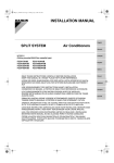
Service Manual
RZQ71~125B8V3B
RZQ100~140B7W1B
Sky-Air Inverter R-410A B series
ESIE05-03.book Page 2 Wednesday, April 6, 2005 4:09 PM
ESIE05-03.book Page i Wednesday, April 6, 2005 4:09 PM
ESIE05-03
Table of Contents
1
1
Introduction
1.1
1.2
1.3
About This Manual ..................................................................................
Combination Overview ............................................................................
Precautions on Handling New Refrigerants ............................................
i–i
i–ii
i–iv
Part 1
System Outline
1
3
General Outline: Outdoor Units
1.1
1.2
1.3
1.4
2
What Is in This Chapter? ........................................................................
RZQ71, 100 and 125 (single phase) .......................................................
RZQ100, 125 and 140 (three phase) ......................................................
1–11
1–12
1–16
What Is in This Chapter? ........................................................................
Pair System ............................................................................................
Twin System ...........................................................................................
Triple System ..........................................................................................
Double Twin System ...............................................................................
Pipe Connection Diameters ....................................................................
Re-using Existing Field Piping ................................................................
Piping Components.................................................................................
1–21
1–22
1–24
1–26
1–27
1–28
1–29
1–35
What Is in This Chapter? ........................................................................
RZQ71B8V3B .........................................................................................
RZQ100~125B8V3B ...............................................................................
RZQ100~140B7W1B ..............................................................................
1–37
1–38
1–39
1–40
Functional Diagrams
Switch Box Layout
4.1
4.2
4.3
4.4
Table of Contents
4
5
3.1
3.2
3.3
3.4
3.5
3.6
3.7
3.8
4
1–3
1–4
1–6
1–8
Specifications
2.1
2.2
2.3
3
What Is in This Chapter? ........................................................................
RZQ71: Outlook and Dimensions ..........................................................
RZQ100~140: Outlook and Dimensions .................................................
RZQ71~140: Installation and Service Space ..........................................
i
ESIE05-03.book Page ii Wednesday, April 6, 2005 4:09 PM
ESIE05-03
1
5
6
3
Wiring Diagrams
5.1
5.2
5.3
5.4
What Is in This Chapter? .........................................................................
RZQ71B8V3B ..........................................................................................
RZQ100~125B8V3B ................................................................................
RZQ100~140B7W1B ...............................................................................
1–41
1–42
1–44
1–46
6.1
6.2
6.3
6.4
What Is in This Chapter? .........................................................................
RZQ71B8V3B ..........................................................................................
RZQ100~125B8V3B ................................................................................
RZQ100~140B7W1B ...............................................................................
1–49
1–50
1–54
1–58
PCB Layout
4
5
ii
Table of Contents
ESIE05-03.book Page iii Wednesday, April 6, 2005 4:09 PM
ESIE05-03
Part 2
Functional Description
1
General Functionality
1.1
1.2
1.3
1.4
1.5
1.6
1.7
1.8
1.9
1.10
1.11
1.12
1.13
1.14
1.15
1.16
1.17
1.18
2
What Is in This Chapter? ........................................................................
Functions of Thermistors ........................................................................
Forced Operating Mode (Emergency Operation)....................................
Outdoor Unit Identification Function........................................................
Simulated Operation Function ................................................................
Restart Standby ......................................................................................
Automatic Restart ...................................................................................
Using Conditions for Remote Controller Thermostat ..............................
Forced Thermostat OFF .........................................................................
Test Run Control ....................................................................................
4-way Valve Control ................................................................................
Pump Down Residual Operation ............................................................
Pump Down Operation ...........................................................................
Defrost Operation ...................................................................................
Freeze Prevention Function ....................................................................
PMV Control ...........................................................................................
Preheating Operation Control .................................................................
Crankcase Heater Control .....................................................................
2–3
2–4
2–6
2–8
2–9
2–10
2–11
2–12
2–14
2–15
2–16
2–17
2–18
2–19
2–22
2–23
2–24
2–25
What Is in This Chapter? ........................................................................
Thermostat Control ................................................................................
Drain Pump Control ...............................................................................
Condensation Avoidance Control ..........................................................
Draft Avoidance Control 1.......................................................................
Draft Avoidance Control 2.......................................................................
Fan and Flap Operations .......................................................................
Indoor Unit Fan Control ..........................................................................
2–27
2–28
2–29
2–31
2–32
2–33
2–34
2–35
Outdoor Unit Functional Concept
3.1
3.2
3.3
3.4
3.5
Table of Contents
What Is in This Chapter? ........................................................................
Function Outline ......................................................................................
Frequency Regulating Functions ...........................................................
Expansion Valve Regulating Functions .................................................
Outdoor Unit Fan Speed Control ...........................................................
3
4
5
Indoor Unit Functional Concept
2.1
2.2
2.3
2.4
2.5
2.6
2.7
2.8
3
1
2–37
2–38
2–41
2–58
2–62
iii
ESIE05-03.book Page iv Wednesday, April 6, 2005 4:09 PM
ESIE05-03
1
Part 3
Troubleshooting
1
1.1
1.2
1.3
1.4
1.5
1.6
1.7
1.8
1.9
1.10
1.11
3
4
Troubleshooting
2
iv
3–3
3–4
3–5
3–25
3–26
3–27
3–31
3–33
3–35
3–38
3–39
Error Codes: Indoor Units
2.1
2.2
2.3
2.4
2.5
2.6
2.7
2.8
2.9
2.10
5
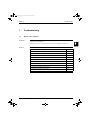
What Is in This Chapter? .........................................................................
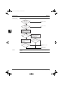
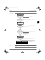
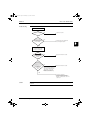
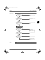
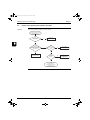
General Troubleshooting Flowchart.........................................................
Overview of General Problems ................................................................
Procedure of Self-Diagnosis by Remote Controller .................................
Fault-diagnosis by Wired Remote Controller ...........................................
Fault-diagnosis by Wireless Remote Controller.......................................
Overview of Error Codes .........................................................................
Troubleshooting by LED Indications ........................................................
Troubleshooting by Remote Controller Display / LED Display.................
Overview of the Outdoor Safety Devices ................................................
Overview of the Indoor Safety Devices ...................................................
What Is in This Chapter? .........................................................................
Malfunctioning Indoor PCB ..............................................................(A1)
Malfunction of Drain Water Level System ........................................(A3)
Malfunctioning Drain System ...........................................................(AF)
Indoor Unit Fan Motor Lock .............................................................(A6)
Swing Flap Motor Malfunction / Lock ............................................... (A7)
Malfunctioning Capacity Setting ...................................................... (AJ)
Thermistor Abnormality ...................................................... (C4, C5, C9)
Malfunctioning Remote Controller Air Thermistor ............................ (CJ)
Humidity Sensor System Malfunction ............................................. (CC)
3–41
3–42
3–43
3–45
3–47
3–49
3–51
3–53
3–55
3–56
Table of Contents
ESIE05-03.book Page v Wednesday, April 6, 2005 4:09 PM
ESIE05-03
3
Error Codes: Outdoor Units
3.1
3.2
3.3
3.4
3.5
3.6
3.7
3.8
3.9
3.10
3.11
3.12
3.13
3.14
3.15
3.16
3.17
3.18
3.19
3.20
3.21
3.22
3.23
4
3–57
3–58
3–59
3–61
3–63
3–65
3–67
3–69
3–71
3–73
3–74
3–76
3–77
3–79
3–80
3–82
3–84
3–86
3–88
3–90
3–91
3–92
3–93
4.3
4.4
4.5
4.6
What Is in This Chapter? ........................................................................ 3–95
Malfunction of Transmission between Indoor and
Outdoor Unit .......................................................................... (U4 or UF) 3–96
Malfunction of Transmission between Indoor Unit and
Remote Controller ........................................................................... (U5) 3–98
Malfunction of Transmission between MAIN Remote Controller
and SUB Remote Controller
(U8) 3–99
Malfunctioning Field Setting Switch ................................................ (UA) 3–100
Centralized Address Setting Error ..................................................(UC) 3–102
Additional Checks for Troubleshooting
5.1
5.2
5.3
5.4
5.5
5.6
5.7
5.8
5.9
Table of Contents
What Is in This Chapter? ........................................................................
Outdoor unit: Checking the Installation Condition ...................................
Outdoor Unit: Checking the Expansion Valve .........................................
Checking the Thermistors .......................................................................
Resistance Conversion Table (Ambient, Coil, Fin) .................................
R3T: Resistance Conversion Table (Discharge Pipe Sensor) ................
Evaluation of Abnormal High Pressure ...................................................
Evaluation of Abnormal Low Pressure ....................................................
Checks ....................................................................................................
1
3
4
5
Error Codes: System Malfunctions
4.1
4.2
5
What Is in This Chapter? ........................................................................
Failure of Outdoor Unit PC Board ....................................................(E1)
Abnormal High Pressure (Detected by the HPS) .............................(E3)
Actuation of Low Pressure Sensor: RZQ71B8V3B ..........................(E4)
Actuation of Low Pressure Switch: RZQ100~140 ............................(E4)
Compressor Motor Lock ...................................................................(E5)
Malfunction of Outdoor Unit Fan Motor ............................................(E7)
Malfunction of Electronic Expansion Valve ......................................(E9)
Malfunctioning in Discharge Pipe Temperature ...............................(F3)
Malfunctioning HPS System ............................................................ (H3)
Abnormal Low Pressure Switch ...................................................... (H4)
Malfunction of Thermistor System ................................. (H9, J3, J5, J6)
Malfunction of Suction Pipe Pressure Sensor ..................................(JC)
Radiation Fin Temperature Increased ............................................. (L4)
DC Output Overcurrent (Instantaneous) .......................................... (L5)
Electronic Thermal (Time Lag) ......................................................... (L8)
Stall Prevention (Time Lag) ............................................................. (L9)
Malfunction of Transmission system (Between Control PCB
and Inverter PCB)
(LC)
Open Phase or Power Supply Voltage Imbalance ........................... (P1)
Malfunction of Radiator Fin Temperature Thermistor ..................... (P4)
Failure of Capacity Setting .............................................................. (PJ)
Gas Shortage (Malfunction) ........................................................... (U0)
Abnormal Power Supply Voltage ................................................... (U2)
3–103
3–104
3–105
3–106
3–107
3–108
3–109
3–110
3–111
v
ESIE05-03.book Page vi Wednesday, April 6, 2005 4:09 PM
ESIE05-03
1
Part 4
Commissioning and Test Run
1
3
2
4
Pre-Test Run Checks
1.1
1.2
1.3
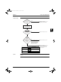
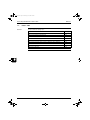
What Is in This Chapter? .........................................................................
Test Run Checks .....................................................................................
Setting the Wireless Remote Controller...................................................
4–3
4–4
4–5
2.1
2.2
What Is in This Chapter? .........................................................................
How to Change the Field Settings with the Wired
Remote Controller....................................................................................
How to Change the Field Settings with the Wireless
Remote Controller....................................................................................
Overview of the Field Settings on the Indoor Units..................................
Overview of the Factory Settings on the Indoor Units..............................
MAIN/SUB Setting when Using Two Remote Controllers........................
Setting the Centralized Group No. ...........................................................
The Field Setting Levels ..........................................................................
Overview of the Field Settings on the Outdoor Units ...............................
Overview of the Factory Settings on the Outdoor Units...........................
Silent Operation ......................................................................................
I-Demand Function .................................................................................
Setting for Low Humidity Application ......................................................
Defrost Start Setting ................................................................................
4–9
Field settings
2.3
2.4
2.5
2.6
2.7
2.8
2.9
2.10
2.11
2.12
2.13
2.14
5
3
4–12
4–13
4–14
4–15
4–16
4–18
4–21
4–23
4–24
4–26
4–28
4–34
Test Run and Operation Data
3.1
3.2
vi
4–10
General Operation Data...........................................................................
Operation Range .....................................................................................
4–36
4–39
Table of Contents
ESIE05-03.book Page vii Wednesday, April 6, 2005 4:09 PM
ESIE05-03
Part 5
Disassembly and Maintenance
1
1
Disassembly and Maintenance: Outdoor Units
1.1
1.2
What Is in This Chapter? ........................................................................
RZQ71~140B ..........................................................................................
5–3
5–4
3
4
5
Table of Contents
vii
ESIE05-03.book Page viii Wednesday, April 6, 2005 4:09 PM
ESIE05-03
1
3
4
5
viii
Table of Contents
ESIE05-03.book Page i Wednesday, April 6, 2005 4:09 PM
ESIE05-03
Introduction
Part 0
1
Introduction
1.1
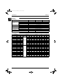
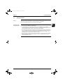
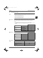
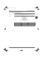
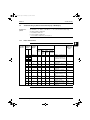
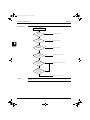
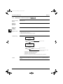
About This Manual
Target group
This service manual is intended for and should only be used by qualified engineers.
Purpose of this
manual
This service manual contains all the information you need to do the necessary repair and maintenance
tasks for the Sky Air RZQ single and three phase, 71~140 class.
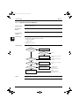
Five parts
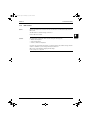
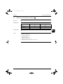
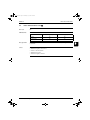
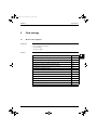
This service manual consists of an introduction, five parts and an index:
Introduction
overview
Note:
Part
See page
Part 1–System Outline
1–1
Part 2–Functional Description
2–1
Part 3–Troubleshooting
3–1
Part 4–Commissioning and Test Run
4–1
Part 5–Disassembly and Maintenance
5–1
4
5
The introduction contains the following topics:
Topic
See page
1.2–Combination Overview
ii
1.3–Precautions on Handling New Refrigerants
iv
3
This Service Manual is about Outdoor Models only. Please refer to the indoor unit Service Manual
ESIE05-04 for details on the indoor units.
i
ESIE05-03.book Page ii Wednesday, April 6, 2005 4:09 PM
Introduction
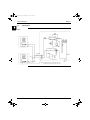
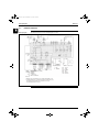
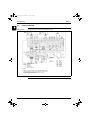
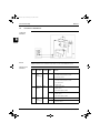
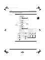
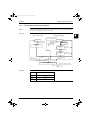
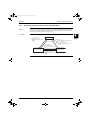
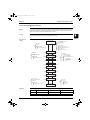
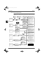
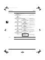
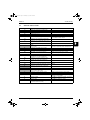
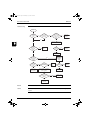
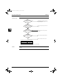
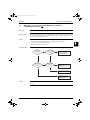
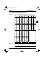
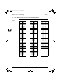
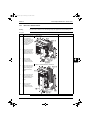
Combination Overview
5
2
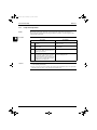
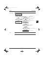
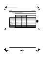
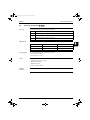
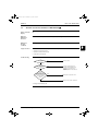
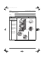
RZQ100B8V3B
3
2
4
3
3
2
4
3
4
3
RZQ125B8V3B
P
RZQ100B7W1B
RZQ125B7W1B
RZQ140B7W1B
ii
P
P
P
FHQ100BUV3B
P
FHQ71BUV3B
FHQ60BUV1B
2
RZQ71B8V3B
P
P
P
2
3
3
2
4
3
4
3
P
P
P
P
P
P
2
4
P
P
2
P
P
2
2
2
2
FBQ125B7V3B
FBQ100B7V3B
FBQ71B7V3B
FBQ60B7V1
FBQ50B7V1
FBQ35B7V1
FFQ60B7V1B
FFQ50B7V1B
3
2
P
2
FAQ100BV3B
4
P
P
FFQ35B7V1B
RZQ140B7W1B
P
2
3
FAQ71BV3B
3
FCQ140DV3B
4
2
P
FUQ125BV3B
RZQ125B7W1B
FCQ125DV3B
2
P
2
FUQ100BV3B
3
FCQ100DV3B
RZQ100B7W1B
P
FUQ71BV3B
3
FCQ71DV3B
4
P
FHQ125BUV3B
RZQ125B8V3B
FCQ125B7V3B
2
FCQ100B7V3B
3
FCQ71B7V3B
RZQ100B8V3B
FCQ60B7V1
2
MODEL
NAME
FCQ50B7V1
RZQ71B8V3B
FHQ50BUV1B
4
MODEL
NAME
FHQ35BUV1B
3
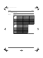
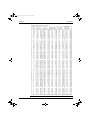
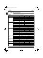
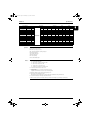
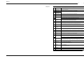
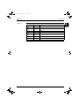
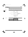
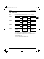
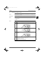
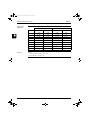
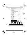
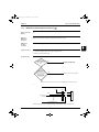
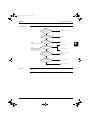
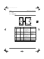
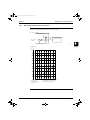
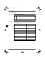
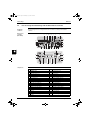
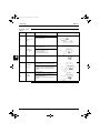
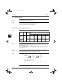
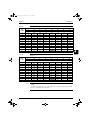
The table below contains the possible combinations between indoor units and outdoor units of the Sky
Air RZQ-series.
FCQ35B7V1
RZQ71~140
FDQ125B7V3B
1
1.2
ESIE05-03
P
3
2
4
3
3
2
4
3
4
3
P
2
P
P
2
P
2
ESIE05-03.book Page iii Wednesday, April 6, 2005 4:09 PM
ESIE05-03
Introduction
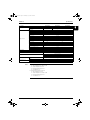
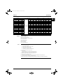
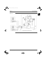
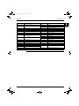
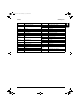
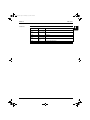
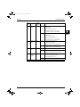
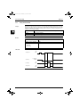
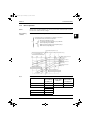
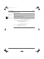
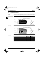
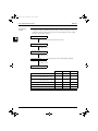
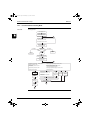
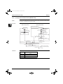
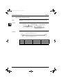
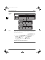
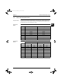
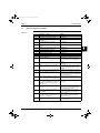
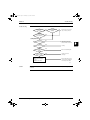
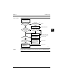
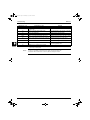
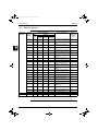
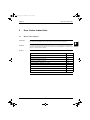
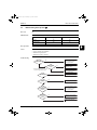
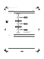
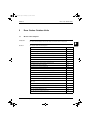
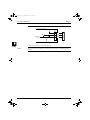
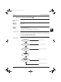
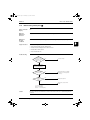
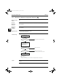
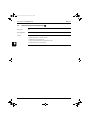
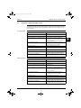
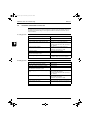
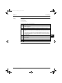
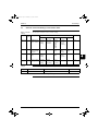
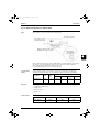
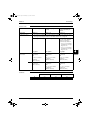
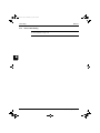
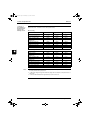
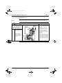
Combination Matrix
Possible indoor combination
Simultaneous operation
Outdoor models
Twin
Triple
Double Twin
35-35
RZQ71B8V3B
(KHRQ22M20TA7)
3
RZQ100B8V3B
50-50
35-35-35
RZQ100B7W1B
(KHRQ22M20TA7)
(KHRQ127H7)
RZQ125B8V3B
60-60
50-50-50
35-35-35-35
RZQ125B7W1B
(KHRQ22M20TA7)
(KHRQ127H7)
(3 x KHRQ22M20TA7)
71-71
50-50-50
35-35-35-35
(KHRQ22M20TA7)
(KHRQ127H7)
(3 x KHRQ22M20TA7)
RZQ140B7W1B
Notes:
1
4
Possible indoor types:
P
FCQ35-71
P
FFQ35-60
P
FHQ35-71
P
FBQ35-71
P
FUQ71
P
FAQ71
5
2
Individual indoor capacities are not given because the combinations are for simultaneous
operation (=indoor units installed in same room).
3
When different indoor models are used in combination, designate the remote controller that is
equipped with the most functions as the main unit. In note 1 are the indoor units mentioned in order
of the possible function (most functions are on FCQ , less functions are on FAQ).
4
Between brackets are the required Refnet kits mentioned, that are necessary to install the
combination.
iii
ESIE05-03.book Page iv Wednesday, April 6, 2005 4:09 PM
Introduction
1
ESIE05-03
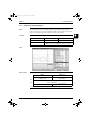
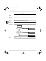
1.3
Precautions on Handling New Refrigerants
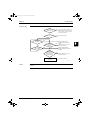
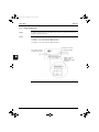
1.3.1
Outline
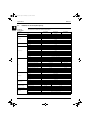
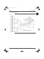
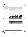
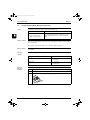
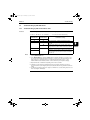
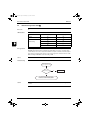
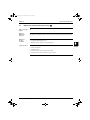
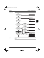
About Refrigerant
R410A
P
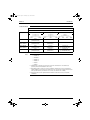
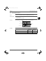
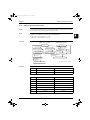
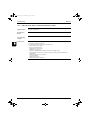
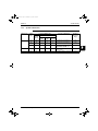
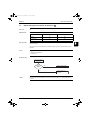
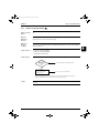
Characteristics of new refrigerant, R410A
1
Performance
Almost the same performance as R22 and R407C.
2
Pressure
Working pressure is approx. 1.4 times more than R22 and R407C.
3
Refrigerant composition
Few problems in composition control, since it is a Quasi-azeotropic mixture refrigerant.
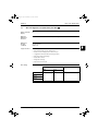
3
HFC units (Units using new refrigerants)
Refrigerant name
Composing
substances
4
Design pressure
Refrigerant oil
Ozone destruction
factor (ODP)
Combustibility
Toxicity
5
R407C
R410A
Non-azeotropic mixture Quasi-azeotropic mixof HFC32, HFC125 and ture of HFC32 and
HFC134a (*1)
JFC125 (*1)
4.15 Mpa (gauge pressure)
3.2 Mpa (gauge pres2
= 42.3 kgf/cm2
sure) = 32.6 kgf/cm
Synthetic oil (Ether)
0
0
None
None
None
None
HCFC units
R22
Single-component refrigerant
2.75Mpa (gauge pressure)
= 28.0 kgf/cm2
Mineral oil (Suniso)
0.05
None
None
*1. Non-azeotropic mixture refrigerant: mixture of two or more refrigerants having different boiling
points.
*2. Quasi-azeotropic mixture refrigerant: mixture of two or more refrigerants having similar boiling
points.
*3. The design pressure is different at each product. Please refer to the installation manual for each
product.
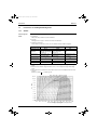
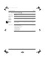
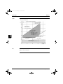
(Reference) 1 Mpa
1 0.19716 kgf / cm2
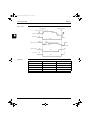
Pressure-Enthalpy curves of HFC-32/125 (50/50wt%)
iv
ESIE05-03.book Page v Wednesday, April 6, 2005 4:09 PM
ESIE05-03
Introduction
P
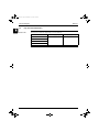
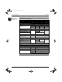
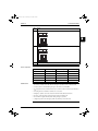
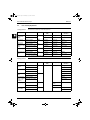
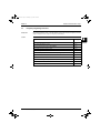
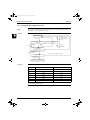
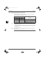
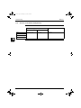
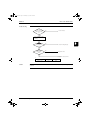
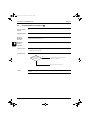
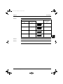
Thermodynamic characteristic of R410A
Temperature
( )
Steam pressure
(kPa)
Liquid
Vapor
Density
(kg/m3 )
Liquid
Vapor
Specific heat at constant
pressure (kJ/kgK)
Liquid
Vapor
Specific enthalpy
(kJ/kg)
Liquid
Vapor
Specific entropy
(kJ/KgK)
Liquid
Vapor
3
4
5
v
ESIE05-03.book Page vi Wednesday, April 6, 2005 4:09 PM
Introduction
1
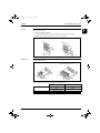
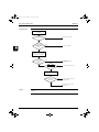
1.3.2
ESIE05-03
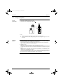
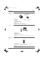
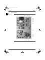
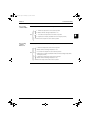
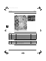
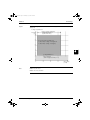
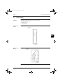
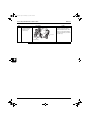
Refrigerant Cylinders
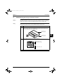
Cylinder
specifications
P
The cylinder is painted refrigerant color (pink).
P
The cylinder valve is equipped with a siphon tube.
Cylilinder
Siphon tube
3
4
5
P
Handling of
cylinders
vi
Note:
1
Refrigerant can be charged in liquid state with cylinder in upright position.
2
Do not lay cylinder on its side during charging, since it causes refrigerant in gas state to enter
the system.
1
Laws and regulations
R410A is liquefied gas, and the High-Pressure Gas Safety Law must be observed in handling
them. Before using, refer to the High-Pressure Gas Safety Law.
The Law stipulates standards and regulations that must be followed to prevent accidents with
high-pressure gases. Be sure to follow the regulations.
2
Handing of vessels
Since R410A is high-pressure gas, it is contained in high-pressure vessels.
Although those vessels are durable and strong, careless handling can cause damage that can lead
to unexpected accidents. Do not drop vessels, let them fall, apply impact or roll them on the ground.
3
Storage
Although R410A is not flammable, it must be stored in a well-ventilated, cool, and dark place in the
same way as any other high-pressure gases.
It should also be noted that high-pressure vessels are equipped with safety devices that releases
gas when the ambient temperature reaches more than a certain level (fusible plug melts) and when
the pressure exceeds a certain level (spring-type safety valve operates).
ESIE05-03.book Page vii Wednesday, April 6, 2005 4:09 PM
ESIE05-03
1.3.4
Introduction
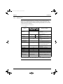
Service Tools
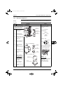
R410A is used under higher working pressure, compared to previous refrigerants (R22,R407C).
Furthermore, the refrigerating machine oil has been changed from Suniso oil to Ether oil, and if oil
mixing is occurred, sludge results in the refrigerants and causes other problems. Therefore, gauge
manifolds and charge hoses that are used with a previous refrigerant (R22,R407C) can not be used
for products that use new refrigerants.
Be sure to use dedicated tools and devices.
P
Tool compatibility
Compatibility
Tool
HFC
R410A
HCFC
R407C
Charging cylinder
Gas detector
P
Do not use the same tools for R22
and R410A.
P
Thread specification differs for
R410A and R407C.
P
Weighting instrument used for
HFCs.
The same tool can be used for
HFCs.
To use existing pump for HFCs,
vacuum pump adaptor must be
installed.
X
X
O
O
X
Vacuum pump
P
P
(pump with reverse flow
preventive function)
O
Weighting instrument
Charge mouthpiece
O
O
Torque wrench
Pipe cutter
O
O
Pipe expander
Pipe bender
O
O
Pipe assembling oil
Refrigerant recovery
device
Refrigerant piping
X
4
5
P
Seal material is different between
R22 and HFCs.
P
Thread specification is different
between R410A and others.
P
For R410A, flare gauge is
necessary.
P
Torque-up for 1/2 and 5/8
P
Due to refrigerating machine oil
change. (No Suniso oil can be used.)
P
Only φ19.1 is changed to 1/2H
material while the previous material is
"O".
X
Flaring tool (Clutch
type)
3
R22
Gauge manifold
Charge hose
Reasons for change
Check your recovery device.
See the chart below.
As for the charge mouthpiece and packing, 1/2UNF20 is necessary for mouthpiece size of charge
hose.
vii
ESIE05-03.book Page viii Wednesday, April 6, 2005 4:09 PM
Introduction
1
ESIE05-03
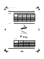
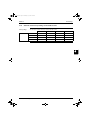
Copper tube
material and
thickness
R407C
Pipe size
3
R410A
Material
Thickness
tmmj
Material
Thickness
tmmj
φ6.4
O
0.8
O
0.8
φ9.5
O
0.8
O
0.8
φ12.7
O
0.8
O
0.8
φ15.9
O
1.0
O
1.0
φ19.1
O
1.0
1/2H
1.0
* O: Soft (Annealed)
H: Hard (Drawn)
Flaring tool
4
5
Flare gauge
P
•
Specifications
Dimension A
Nominal size
viii
A +0
-0.4
Tube O.D.
Do
Class-2 (R410A)
Class-1 (Conventional)
1/4
6.35
9.1
9.0
3/8
9.52
13.2
13.0
1/2
12.70
16.6
16.2
5/8
15.88
19.7
19.4
3/4
19.05
24.0
23.3
ESIE05-03.book Page ix Wednesday, April 6, 2005 4:09 PM
ESIE05-03
Introduction
P
•
Differences
Change of dimension A
Dimension A
For class-1: R407C
For class-2: R410A
Conventional flaring tools can be used when the work process is changed. (change of work process)
Previously, a pipe extension margin of 0 to 0.5mm was provided for flaring. For R410A air
conditioners, perform pipe flaring with a pipe extension margin of 1.0 to 1.5 mm. (For clutch type only)
Conventional tool with pipe extension margin adjustment can be used.
3
Torque wrench
4
P
•
Specifications
Dimension B
5
Unit:mm
Nominal size
Class-1
Class-2
Previous
1/2
5/8
24
27
26
29
24
27
No change in tightening torque
No change in pipes of other sizes
P
•
Differences
Change of dimension B
Only 1/2", 5/8" are extended
For class-1: R407C
For class-2: R410A
Dimension B
ix
ESIE05-03.book Page x Wednesday, April 6, 2005 4:09 PM
Introduction
1
ESIE05-03
Vacuum pump with
check valve
Vacuum pump adaptor
(Reverse flow preventive
vacuum adaptor)
P
•
3
•
P
•
•
4
Specifications
Discharge speed
50 l/min (50Hz)
60 l/min (60Hz)
Suction port UNF7/16-20(1/4 Flare)
UNF1/2-20(5/16 Flare) with adaptor
z Maximum degree of vacuum
–100.7 kpa ( 5 torr – 755 mmHg)
Differences
Equipped with function to prevent reverse oil flow
Previous vacuum pump can be used by installing adaptor.
Leak tester
5
P
•
•
P
•
Specifications
Hydrogen detecting type, etc.
Applicable refrigerants
R410A, R407C, R404A, R507A, R134a, etc.
Differences
Previous testers detected chlorine. Since HFCs do not contain chlorine, new tester detects
hydrogen.
Refrigerant oil (Air
compal)
P
•
•
P
•
x
Specifications
Contains synthetic oil, therefore it can be used for piping work of every refrigerant cycle.
Offers high rust resistance and stability over long period of time.
Differences
Can be used for R410A and R22 units.
ESIE05-03.book Page xi Wednesday, April 6, 2005 4:09 PM
ESIE05-03
Introduction
Gauge manifold for
R410A
P
•
•
•
•
•
P
•
•
Specifications
High pressure gauge
- 0.1 to 5.3 MPa (-76 cmHg to 53 kg/cm2)
Low pressure gauge
- 0.1 to 3.8 MPa (-76 cmHg to 38 kg/cm2)
1/4" → 5/16" (2min → 2.5min)
No oil is used in pressure test of gauges.
→ For prevention of contamination
Temperature scale indicates the relationship between pressure and temperature in gas saturated
state.
Differences
Change in pressure
Change in service port diameter
Charge hose for
R410A
3
4
5
(Hose with ball valve)
P
•
•
•
P
•
•
•
Specifications
Working pressure 5.08 MPa (51.8 kg/cm2)
Rupture pressure 25.4 MPa (259 kg/cm2)
Available with and without hand-operate valve that prevents refrigerant from outflow.
Differences
Pressure proof hose
Change in service port diameter
Use of nylon coated material for HFC resistance
xi
ESIE05-03.book Page xii Wednesday, April 6, 2005 4:09 PM
Introduction
1
ESIE05-03
Charging cylinder
Can not be used
P
•
3
P
•
Specifications
Use weigher for refrigerant charge listed below to charge directly from refrigerant cylinder.
Differences
The cylinder can not be used for mixed refrigerant since mixing ratio is changed during charging.
When R410A is charged in liquid state using charging cylinder, foaming phenomenon is
generated inside charging cylinder.
4
Weigher for
refrigerant charge
5
P
•
•
•
P
•
Specifications
High accuracy
TA101A (for 10-kg cylinder) = ± 2g
TA101B (for 20-kg cylinder) = ± 5g
Equipped with pressure-resistant sight glass to check liquid refrigerant charging.
A manifold with separate ports for HFCs and previous refrigerants is equipped as standard
accessories.
Differences
Measurement is based on weight to prevent change of mixing ratio during charging.
Charge mouthpiece
P
•
•
P
•
•
xii
Specifications
For R410A, 1/4"→ 5/16" (2min → 2.5min)
Material is changed from CR to H-NBR.
Differences
Change of thread specification on hose connection side (For the R410A use)
Change of sealer material for the HFCs use.
ESIE05-03.book Page 1 Wednesday, April 6, 2005 4:09 PM
ESIE05-03
1
4
Part 1
System Outline
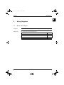
What is in this part?
Part 1 – System Outline
3
This part contains the following chapters:
Chapter
See page
1–General Outline: Outdoor Units
1–3
2–Specifications
1–11
3–Functional Diagrams
1–21
4–Switch Box Layout
1–37
5–Wiring Diagrams
1–41
6–PCB Layout
1–49
4
5
1–1
ESIE05-03.book Page 2 Wednesday, April 6, 2005 4:09 PM
ESIE05-03
11
3
5
1–2
Part 1 – System Outline
ESIE05-03.book Page 3 Wednesday, April 6, 2005 4:09 PM
ESIE05-03
General Outline: Outdoor Units
Part 1
1
General Outline: Outdoor Units
1.1
What Is in This Chapter?
Introduction
General outline
Part 1 – System Outline
This chapter contains the following information on the outdoor units:
P
Outlook and dimensions
P
Installation and service space
P
Components
1
3
This chapter contains the following general outlines:
General outline
See page
1.2–RZQ71: Outlook and Dimensions
1–4
1.3–RZQ100~140: Outlook and Dimensions
1–6
1.4–RZQ71~140: Installation and Service Space
1–8
4
5
1–3
ESIE05-03.book Page 4 Wednesday, April 6, 2005 4:09 PM
General Outline: Outdoor Units
11
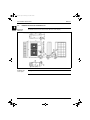
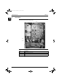
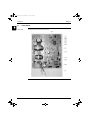
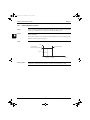
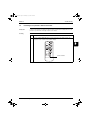
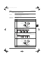
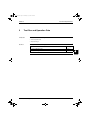
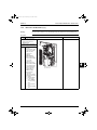
1.2
ESIE05-03
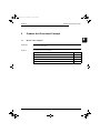
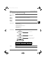
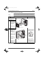
RZQ71: Outlook and Dimensions
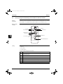
Outlook and
dimensions
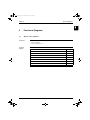
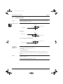
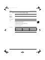
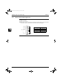
The illustration below shows the outlook and the dimensions of the unit (mm).
HOLE FOR ANCHOR
BOLT 4-M12
3
4
5
Installation and
service space
1–4
See page 1–8.
Part 1 – System Outline
ESIE05-03.book Page 5 Wednesday, April 6, 2005 4:09 PM
ESIE05-03
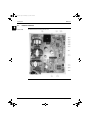
Components
General Outline: Outdoor Units
1
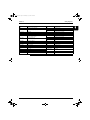
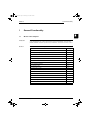
The table below contains the different components of the unit.
No.
Component
1
Gas pipe connection
2
Liquid pipe connection
3
Service port (inside the unit)
4
Grounding terminal M5 (inside the switch box)
5
Refrigerant piping intake
6
Power supply wiring intake
7
Control wiring intake
8
Drain outlet
3
4
5
Part 1 – System Outline
1–5
ESIE05-03.book Page 6 Wednesday, April 6, 2005 4:09 PM
General Outline: Outdoor Units
11
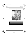
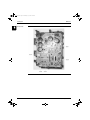
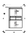
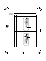
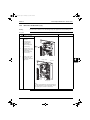
1.3
ESIE05-03
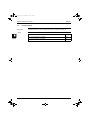
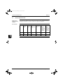
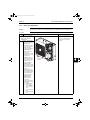
RZQ100~140: Outlook and Dimensions
Outlook and
dimensions
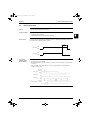
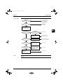
The illustration below shows the outlook and the dimensions of the unit (mm).
HOLE FOR ANCHOR
BOLT 4-M12
3
4
5
Installation and
service space
1–6
See page 1–8.
Part 1 – System Outline
ESIE05-03.book Page 7 Wednesday, April 6, 2005 4:09 PM
ESIE05-03
Components
General Outline: Outdoor Units
1
The table below contains the different components of the unit.
No.
Component
1
Gas pipe connection
2
Liquid pipe connection
3
Service port (inside the unit)
4
Electronic connection and grounding terminal M5 (inside the switch box)
5
Refrigerant piping intake
6
Power supply wiring intake
7
Control wiring intake
8
Drain outlet
3
4
5
Part 1 – System Outline
1–7
ESIE05-03.book Page 8 Wednesday, April 6, 2005 4:09 PM
General Outline: Outdoor Units
11
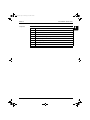
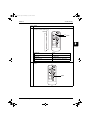
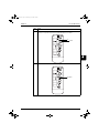
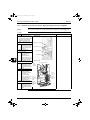
1.4
ESIE05-03
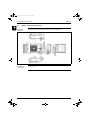
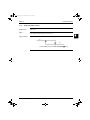
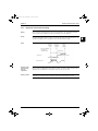
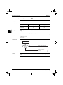
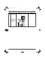
RZQ71~140: Installation and Service Space
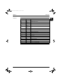
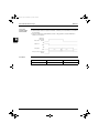
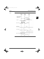
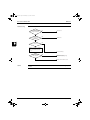
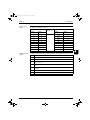
Non stacked
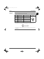
The illustrations and table below show the required installation and service space (mm). The values
between brackets are for the 100~140 class.
3
4
5
Suction side obstacle
1
In these cases, close the bottom
of the installation frame to
prevent discharged air from being
bypassed
2
In these cases, only 2 units can
be installed
Discharge side obstacle
Left side obstacle
Right side obstacle
This situation is not allowed
Top side obstacle
Obstacle is present
1–8
Part 1 – System Outline
ESIE05-03.book Page 9 Wednesday, April 6, 2005 4:09 PM
ESIE05-03
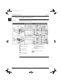
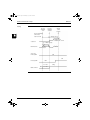
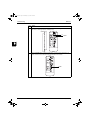
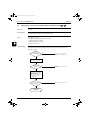
Stacked
General Outline: Outdoor Units
The illustration below shows the required installation and service space (mm). The values in brackets
are for the 100~140 class.
P
Do not stack more than one unit.
P
± 100 mm is required as the dimension for laying the upper outdoor unit’s drain pipe.
P
Get the portion A sealed so that air from the outlet does not bypass.
Obstacles exist in front of the outlet side
1
Obstacles exist in front of the air inlet
3
4
Multiple rows
The illustration below shows the required installation and service space (mm). The values in brackets
are for the 100~140 class.
Installation of one unit per row
Installing multiple units (2 units or more)
in lateral connection per row
5
Relation of dimensions of H, A and L are shown in the table below.
L≤H
H<L
Part 1 – System Outline
L
A
0 < L ≤ 1/2H
150 (250)
1/2H < L
200 (300)
installation impossible
1–9
ESIE05-03.book Page 10 Wednesday, April 6, 2005 4:09 PM
General Outline: Outdoor Units
ESIE05-03
11
3
4
5
1–10
Part 1 – System Outline
ESIE05-03.book Page 11 Wednesday, April 6, 2005 4:09 PM
ESIE05-03
Specifications
Part 1
2
Specifications
2.1
What Is in This Chapter?
Introduction
Outdoor units
This chapter contains the following information:
P
Technical specifications
P
Electrical specifications
P
Electrical data
1
3
This chapter contains the following specifications:
Specifications
See page
2.2–RZQ71, 100 and 125 (single phase)
1–12
2.3–RZQ100, 125 and 140 (three phase)
1–16
4
5
Part 1 – System Outline
1–11
ESIE05-03.book Page 12 Wednesday, April 6, 2005 4:09 PM
Specifications
11
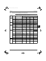
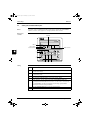
2.2
ESIE05-03
RZQ71, 100 and 125 (single phase)
Technical
specifications
The table below contains the technical specifications.
Specification
RZQ71B8V3B
Colour
RZQ100B8V3B
RZQ125B8V3B
Ivory white
Casing
Material
Packing Height
Painted galvanized steel plate
900 mm
Packing Width
1475 mm
980 mm
Packing Depth
420 mm
Dimensions
Unit Height
3
770 mm
Unit Width
Unit Depth
320 mm
Machine weight
68 kg
Gross weight
72 kg
106 kg
Weight
Length
2
Fin pitch
Nr. of passes
Face area
111 kg
857 mm
Nr. of rows
4
1345 mm
900 mm
1.40 mm
3
5
0.641 m²
1.131 m²
Heat exchanger
Nr. of stages
34
Empty tubeplate hole
Tube type
Hi-XSS(8)
Fin type
WF fin
Fin treatment
5
60
0
Anti-corrosion treatment (PE)
Type
Propeller
Discharge direction
Horizontal
Quantity
1
2
Air flow rate (nominal at 230 V) cooling
54.50 m³/min
103.00 m³/min
99.00 m³/min
Air flow rate (nominal at 230 V) heating
48.10 m³/min
101.00 m³/min
100.00 m³/min
Fan motor quantity
1
2
Fan
Fan motor model
KFD-325-70-8A
Motor speed (nominal at 230 V) Nr. of steps
8
Motor speed (nominal at 230 V) cooling
818 rpm
789 rpm
782 rpm
Motor speed (nominal at 230 V) heating
715 rpm
775 rpm
767 rpm
Motor output
70 W
Motor Drive
direct drive
Quantity
Motor model
Motor type
Compressor
Motor output
1
2YC838XD
JT100G-VD
Hermetically sealed swing
compressor
Hermetically sealed scroll compressor
1800 W
Motor starting method
2200 W
Inverter driven
Motor crankcase heater
33 W
Cooling min.
-15.0°C DB
Cooling max.
50.0°C DB
Heating min.
-20.0°C WB
Operation range
Heating max.
Sound level (nominal)
Sound level (night quiet)
15.5°C WB
Cooling sound power
63.0 dBA
65.0 dBA
Cooling sound pressure
47.0 dBA
49.0 dBA
50.0 dBA
Heating sound pressure
49.0 dBA
51.0 dBA
52.0 dBA
Cooling sound pressure
43.0 dBA
Type
Charge
66.0 dBA
45.0 dBA
R-410A
2.80 kg
4.30 kg
Refrigerant
Control
Nr. of circuits
1–12
Expansion valve (electronic type)
1
Part 1 – System Outline
ESIE05-03.book Page 13 Wednesday, April 6, 2005 4:09 PM
ESIE05-03
Specifications
Specification
RZQ71B8V3B
Type
RZQ100B8V3B
1
RZQ125B8V3B
Daphne FVC50K
Daphne FVC68D
0.8 l
1.0 l
Refrigerant oil
Charged volume
Liquid quantity
1
Liquid type
Flare connection
Liquid diameter (OD)
9.52 mm
Gas quantity
1
Gas type
Flare connection
Gas diameter (OD)
15.9 mm
Drain quantity
3
Drain type
Piping connections
Hole
Drain diameter (OD)
26.0 mm
Piping length min.
5m
Piping length max.
50 m
Piping length equivalent
70 m
Piping length chargeless
Additional refrigerant charge
95 m
30 m
See installation manual 4PW21412-1
Installation height difference max.
30.0 m
Max. intern unit level difference
0.50 m
Heat insulation
Both liquid and gas pipes
Defrost method
Pressure equalising
Defrost control
Sensor for outdoor heat exchanger temperature
Capacity control method
3
75 m
4
Inverter controlled
High pressure switch
Safety devices
Fan motor thermal protector
Fuse
Standard accessories
Item
Quantity
Standard accessories
2
Item
Installation manual
Quantity
Notes:
1
2
Part 1 – System Outline
5
Tie-wraps
1
Nominal cooling capacities are based on:
P
Indoor temperature: 27.0°C DB/19.0°C WB
P
Outdoor temperature: 35.0°C DB
P
Equivalent refrigerant piping: 7.5 m
P
Level difference: 0 m
Nominal heating capacities are based on:
P
Indoor temperature: 20°C DB
P
Outdoor temperature: 7.0°C DB/6.0° C WB
P
Equivalent refrigerant piping: 7.5 m
P
Level difference: 0 m
1–13
ESIE05-03.book Page 14 Wednesday, April 6, 2005 4:09 PM
Specifications
11
ESIE05-03
Electrical
specifications
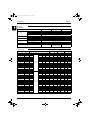
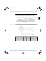
The table below contains the electrical specifications.
Specification
RZQ71B8V3B
RZQ100B8V3B
Name
RZQ125B8V3B
V3B
Phase
1~
Power supply
Frequency
50 Hz
Voltage
230 V
Zmax. List
Complies to EN61000-3-11
Current
Recommended fuses
20 A
32 A
Mininum
207 V
Voltage range
Maximum
Wire connections
3
253 V
For power supply - remark
See installation manual 4PW21412-1
For connection with indoor - remark
See installation manual 4PW21412-1
Power supply intake
Outdoor unit only
Notes
See separate drawing for
electrical data.
See separate drawing for electrical data.
Power supply intake for FDQ is outdoor and indoor unit.
Electrical data
4
5
Unit combination
Power supply
Indoor unit
Outdoor unit
Hz-Volts
FCQ71DV3B
RZQ71B8V3B
FCQ71B7V3B
Voltage range
Compressor
OFM
IFM
MCA
TOCA
MFA
MSC
RLA
kW
FLA
kW
50-230
16.8
16.8
20
16.2
16.2
0.07
0.3
0.030
FLA
0.3
RZQ71B8V3B
50-230
17.1
17.1
20
16.2
16.2
0.07
0.3
0.045
0.6
FCQ35B7V1x2
RZQ71B8V3B
50-230
17.7
17.7
20
16.2
16.2
0.07
0.3
0.045x2
0.6x2
FFQ35B7V1Bx2
RZQ71B8V3B
50-230
17.7
17.7
20
16.2
16.2
0.07
0.3
0.055x2
0.6x2
FBQ71B7V3B
RZQ71B8V3B
50-230
17.4
17.4
20
16.2
16.2
0.07
0.3
0.125
0.9
FBQ35B7V1x2
RZQ71B8V3B
50-230
17.5
17.5
20
16.2
16.2
0.07
0.3
0.065x2
0.5x2
FHQ71BUV1B
RZQ71B8V3B
50-230
17.1
17.1
20
16.2
16.2
0.07
0.3
0.062
0.6
FHQ35BUV1Bx2
RZQ71B8V3B
50-230
17.7
17.7
20
16.2
16.2
0.07
0.3
0.062x2
0.6x2
Max.50Hz-253V
Min.50Hz-207V
FAQ71BUV1B
RZQ71B8V3B
50-230
16.8
16.8
20
16.2
16.2
0.07
0.3
0.043
0.3
FUQ71BUV1B
RZQ71B8V3B
50-230
17.2
17.2
20
16.2
16.2
0.07
0.3
0.045
0.7
FCQ100DV3B
RZQ100B8V3B
50-230
24.7
24.7
32
23.4
23.4
0.07+0.07
0.3+0.3
0.120
0.7
FCQ100B7V3B
RZQ100B8V3B
50-230
25.0
25.0
32
23.4
23.4
0.07+0.07
0.3+0.3
0.090
1.0
FCQ50B7V1x2
RZQ100B8V3B
50-230
25.2
25.2
32
23.4
23.4
0.07+0.07
0.3+0.3
0.045x2
0.6x2
FCQ35B7V1x3
RZQ100B8V3B
50-230
25.8
25.8
32
23.4
23.4
0.07+0.07
0.3+0.3
0.045x3
0.6x3
FFQ50B7V1Bx2
RZQ100B8V3B
50-230
25.4
25.4
32
23.4
23.4
0.07+0.07
0.3+0.3
0.055x2
0.7x2
FFQ35B7V1Bx3
RZQ100B8V3B
50-230
25.8
25.8
32
23.4
23.4
0.07+0.07
0.3+0.3
0.055x3
0.6x3
FBQ100B7V3B
RZQ100B8V3B
50-230
25.0
25.0
32
23.4
23.4
0.07+0.07
0.3+0.3
0.135
1.0
FBQ50B7V1x2
RZQ100B8V3B
50-230
25.4
25.4
32
23.4
23.4
0.07+0.07
0.3+0.3
0.085x2
0.7x2
0.5x3
Max.50Hz-253V
Min.50Hz-207V
FBQ35B7V1x3
RZQ100B8V3B
50-230
25.5
25.5
32
23.4
23.4
0.07+0.07
0.3+0.3
0.065x3
FHQ100BUV1B
RZQ100B8V3B
50-230
24.7
24.7
32
23.4
23.4
0.07+0.07
0.3+0.3
0.130
0.7
FHQ50BUV1Bx2
RZQ100B8V3B
50-230
25.2
25.2
32
23.4
23.4
0.07+0.07
0.3+0.3
0.062x2
0.6x2
FHQ35BUV1Bx3
RZQ100B8V3B
50-230
25.8
25.8
32
23.4
23.4
0.07+0.07
0.3+0.3
0.062x3
0.6x3
FAQ100BUV1B
RZQ100B8V3B
50-230
24.4
24.4
32
23.4
23.4
0.07+0.07
0.3+0.3
0.049
0.4
FUQ100BUV1B
RZQ100B8V3B
50-230
25.1
25.1
32
23.4
23.4
0.07+0.07
0.3+0.3
0.090
1.1
1–14
Part 1 – System Outline
ESIE05-03.book Page 15 Wednesday, April 6, 2005 4:09 PM
ESIE05-03
Specifications
Unit combination
Power supply
Compressor
OFM
IFM
FCQ125DV3B
RZQ125B8V3B
50-230
24.7
24.7
32
23.4
23.4
0.07+0.07
0.3+0.3
0.120
0.7
FCQ125B7V3B
RZQ125B8V3B
50-230
25.0
25.0
32
23.4
23.4
0.07+0.07
0.3+0.3
0.090
1.0
FCQ60B7V1x2
RZQ125B8V3B
50-230
25.2
25.2
32
23.4
23.4
0.07+0.07
0.3+0.3
0.045x2
0.6x2
FCQ50B7V1x3
RZQ125B8V3B
50-230
25.8
25.8
32
23.4
23.4
0.07+0.07
0.3+0.3
0.045x3
0.6x3
FCQ35B7V1x4
RZQ125B8V3B
50-230
26.4
26.4
32
23.4
23.4
0.07+0.07
0.3+0.3
0.045x4
0.6x4
FFQ60B7V1Bx2
RZQ125B8V3B
50-230
25.4
25.4
32
23.4
23.4
0.07+0.07
0.3+0.3
0.055x2
0.7x2
FFQ50B7V1Bx3
RZQ125B8V3B
50-230
26.1
26.1
32
23.4
23.4
0.07+0.07
0.3+0.3
0.055x3
0.7x3
FFQ35B7V1Bx4
RZQ125B8V3B
50-230
26.4
26.4
32
23.4
23.4
0.07+0.07
0.3+0.3
0.055x4
0.6x4
FBQ125B7V3B
RZQ125B8V3B
50-230
25.4
25.4
32
23.4
23.4
0.07+0.07
0.3+0.3
0.225
1.4
FBQ60B7V1x2
RZQ125B8V3B
50-230
25.8
25.8
32
23.4
23.4
0.07+0.07
0.3+0.3
0.125x2
0.9x2
FBQ50B7V1x3
RZQ125B8V3B
50-230
26.1
26.1
32
23.4
23.4
0.07+0.07
0.3+0.3
0.085x3
0.7x3
FBQ35B7V1x4
RZQ125B8V3B
50-230
26.0
26.0
32
23.4
23.4
0.07+0.07
0.3+0.3
0.065x4
0.5x4
FHQ125BUV1B
RZQ125B8V3B
50-230
24.7
24.7
32
23.4
23.4
0.07+0.07
0.3+0.3
0.130
0.7
FHQ60BUV1Bx2
RZQ125B8V3B
50-230
25.2
25.2
32
23.4
23.4
0.07+0.07
0.3+0.3
0.062x2
0.6x2
FHQ50BUV1Bx3
RZQ125B8V3B
50-230
25.8
25.8
32
23.4
23.4
0.07+0.07
0.3+0.3
0.062x3
0.6x3
Max.50Hz-253V
Min.50Hz-207V
FHQ35BUV1Bx4
RZQ125B8V3B
50-230
26.4
26.4
32
23.4
23.4
0.07+0.07
0.3+0.3
0.062x4
0.6x4
FUQ125BUV1B
RZQ125B8V3B
50-230
25.1
25.1
32
23.4
23.4
0.07+0.07
0.3+0.3
0.090
1.1
FDQ125B7V3B
RZQ125B8V3B
50-230
28.2
28.2
32
23.4
23.4
0.07+0.07
0.3+0.3
0.500
4.2
Symbols:
1
3
4
MCA: Min. Circuit Amps
TOCA: Total Over-current Amps
MFA: Max. Fuse Amps (see note 7)
MSC : Max. current during the starting compressor
RLA : Rated Load Amps
OFM : Outdoor Fan Motor
5
IFM : Indoor Fan Motor
FLA : Full Load Amps
kW : Fan Motor Rated Output
Notes:
Part 1 – System Outline
1
RLA is based on the following conditions:
P
Power supply: 50Hz 230V
P
Indoor temp. - cooling: 27°C DB/19.0°C WB
P
Indoor temp. - heating: 20.0°C DB
P
Outdoor temp. - cooling: 35.0°C DB
P
Outdoor temp. - heating: 7.0°C DB/6.0°C WB
2
TOCA means the total value of each OC set.
3
Voltage range
Units are suitable for use on electrical systems where voltage
supplied to unit terminals is not below or above listed range limits.
4
Maximum allowable voltage variation between phases is 2%.
5
MCA represents maximum input current.
MFA represents capacity which may accept MCA. (Next lower standard fuse rating, minimum 15A)
6
Select wire size based on the larger value of MCA or TOCA.
7
MFA is used to select the circuit breaker and the ground fault circuit interruptor. (earth leakage circuit breaker)
1–15
ESIE05-03.book Page 16 Wednesday, April 6, 2005 4:09 PM
Specifications
11
2.3
ESIE05-03
RZQ100, 125 and 140 (three phase)
Technical
specifications
The table below contains the technical specifications.
Specification
RZQ100B7W1B
RZQ125B7W1B
Colour
RZQ140B7W1B
Ivory white
Casing
Material
Painted galvanized steel plate
Packing Height
1475 mm
Packing Width
980 mm
Packing Depth
420 mm
Unit Height
1345 mm
Unit Width
900 mm
Unit Depth
320 mm
Machine weight
106 kg
Dimensions
3
Weight
Gross weight
111 kg
Length
857 mm
Nr. of rows
2
Fin pitch
4
1.40 mm
Nr. of passes
5
Face area
1.131 m²
Heat exchanger
Nr. of stages
60
Empty tubeplate hole
0
Tube type
Hi-XSS(8)
Fin type
WF fin
Fin treatment
5
Anti-corrosion treatment (PE)
Type
Propeller
Discharge direction
Horizontal
Quantity
2
Air flow rate (nominal at 230 V) cooling
103.00 m³/min
99.00 m³/min
Air flow rate (nominal at 230 V) heating
101.00 m³/min
100.00 m³/min
Fan motor quantity
2
Fan
Fan motor model
KFD-325-70-8A
Motor speed (nominal at 230 V) Nr. of steps
8
Motor speed (nominal at 230 V) cooling
789 rpm
782 rpm
Motor speed (nominal at 230 V) heating
775 rpm
767 rpm
Motor output
70 W
Motor Drive
direct drive
Quantity
1
Motor model
JT1G-VDYR@T
Motor type
Hermetically sealed scroll compressor
Compressor
Motor output
2200 W
Motor starting method
Inverter driven
Motor crankcase heater
33 W
Cooling min.
-15.0°C DB
Cooling max.
50.0°C DB
Heating min.
-20.0°C WB
Operation range
Heating max.
Sound level (nominal)
Sound level (night quiet)
15.5°C WB
Cooling sound power
65.0 dBA
66.0 dBA
Cooling sound pressure
49.0 dBA
50.0 dBA
Heating sound pressure
51.0 dBA
Cooling sound pressure
Type
52.0 dBA
45.0 dBA
R-410A
Charge
4.30 kg
Control
Expansion valve (electronic type)
Refrigerant
Nr. of circuits
1–16
1
Part 1 – System Outline
ESIE05-03.book Page 17 Wednesday, April 6, 2005 4:09 PM
ESIE05-03
Specifications
Specification
RZQ100B7W1B
Type
RZQ125B7W1B
1
RZQ140B7W1B
Daphne FVC68D
Refrigerant oil
Charged volume
Liquid quantity
Liquid type
1
Flare connection
Liquid diameter (OD)
Gas quantity
9.52 mm
1
Gas type
Flare connection
Gas diameter (OD)
Drain quantity
Drain type
Piping connections
1.0 l
15.9 mm
3
Hole
Drain diameter (OD)
26.0 mm
Piping length min.
5m
Piping length max.
75 m
Piping length equivalent
95 m
Piping length chargeless
30 m
Additional refrigerant charge
See installation manual 4PW21412-1
Installation height difference max.
30.0 m
Max. intern unit level difference
0.50 m
Heat insulation
Both liquid and gas pipes
Defrost method
Pressure equalising
Defrost control
Sensor for outdoor heat exchanger temperature
Capacity control method
3
4
Inverter controlled
High pressure switch
Safety devices
Fan motor thermal protector
Fuse
Standard accessories
Item
Quantity
Standard accessories
2
Item
Installation manual
Quantity
Notes:
1
2
Part 1 – System Outline
5
Tie-wraps
1
Nominal cooling capacities are based on:
P
Indoor temperature: 27.0°C DB/19.0°C WB
P
Outdoor temperature: 35.0°C DB
P
Equivalent refrigerant piping: 7.5 m
P
Level difference: 0 m
Nominal heating capacities are based on:
P
Indoor temperature: 20°C DB
P
Outdoor temperature: 7.0°C DB/6.0° C WB
P
Equivalent refrigerant piping: 7.5 m
P
Level difference: 0 m
1–17
ESIE05-03.book Page 18 Wednesday, April 6, 2005 4:09 PM
Specifications
11
ESIE05-03
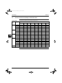
Electrical
specifications
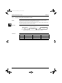
The table below contains the electrical specifications.
Specification
RZQ100B7W1B
RZQ125B7W1B
Name
RZQ140B7W1B
W1B
Phase
3N~
Power supply
Frequency
50 Hz
Voltage
400 V
Zmax. List
Complies to EN61000-3-11
Current
Recommended fuses
20 A
Mininum
360 V
Voltage range
Maximum
Wire connections
3
4
5
440 V
For power supply - remark
See installation manual 4PW21412-1
For connection with indoor - remark
See installation manual 4PW21412-1
Power supply intake
Outdoor unit only
Notes
See separate drawing for
electrical data.
See separate drawing for
electrical data.
See separate drawing for
electrical data.
Power supply intake for FDQ is
outdoor and indoor unit.
Electrical data
Unit combination
Power supply
Voltage range
Compressor
OFM
IFM
Indoor unit
Outdoor unit
Hz-Volts
MCA
TOCA
MFA
MSC
RLA
kW
FLA
kW
FCQ100DV3B
RZQ100B7W1B
50-400
14.2
14.2
20
12.9
12.9
0.07+0.07
0.3+0.3
0.120
0.7
FCQ100B7V3B
RZQ100B7W1B
50-400
14.5
14.5
20
12.9
12.9
0.07+0.07
0.3+0.3
0.090
1.0
FCQ50B7V1x2
RZQ100B7W1B
50-400
14.7
14.7
20
12.9
12.9
0.07+0.07
0.3+0.3
0.045x2
0.6x2
FCQ35B7V1x3
RZQ100B7W1B
50-400
15.3
15.3
20
12.9
12.9
0.07+0.07
0.3+0.3
0.045x3
0.6x3
FFQ50B7V1Bx2
RZQ100B7W1B
50-400
14.9
14.9
20
12.9
12.9
0.07+0.07
0.3+0.3
0.055x2
0.7x2
FFQ35B7V1Bx3
RZQ100B7W1B
50-400
15.3
15.3
20
12.9
12.9
0.07+0.07
0.3+0.3
0.055x3
0.6x3
FBQ100B7V3B
RZQ100B7W1B
50-400
14.5
14.5
20
12.9
12.9
0.07+0.07
0.3+0.3
0.135
1.0
FBQ50B7V1x2
RZQ100B7W1B
50-400
14.9
14.9
20
12.9
12.9
0.07+0.07
0.3+0.3
0.085x2
0.7x2
0.5x3
Max.50Hz-440V
Min.50Hz-360V
FLA
FBQ35B7V1x3
RZQ100B7W1B
50-400
15.0
15.0
20
12.9
12.9
0.07+0.07
0.3+0.3
0.065x3
FHQ100BUV1B
RZQ100B7W1B
50-400
14.2
14.2
20
12.9
12.9
0.07+0.07
0.3+0.3
0.130
0.7
FHQ50BUV1Bx2
RZQ100B7W1B
50-400
14.7
14.7
20
12.9
12.9
0.07+0.07
0.3+0.3
0.062x2
0.6x2
FHQ35BUV1Bx3
RZQ100B7W1B
50-400
15.3
15.3
20
12.9
12.9
0.07+0.07
0.3+0.3
0.062x3
0.6x3
FAQ100BUV1B
RZQ100B7W1B
50-400
13.9
13.9
20
12.9
12.9
0.07+0.07
0.3+0.3
0.049
0.4
FUQ100BUV1B
RZQ100B7W1B
50-400
14.6
14.6
20
12.9
12.9
0.07+0.07
0.3+0.3
0.090
1.1
FCQ125DV3B
RZQ125B7W1B
50-400
14.2
14.2
20
12.9
12.9
0.07+0.07
0.3+0.3
0.120
0.7
FCQ125B7V3B
RZQ125B7W1B
50-400
14.5
14.5
20
12.9
12.9
0.07+0.07
0.3+0.3
0.090
1.0
FCQ60B7V1x2
RZQ125B7W1B
50-400
14.7
14.7
20
12.9
12.9
0.07+0.07
0.3+0.3
0.045x2
0.6x2
FCQ50B7V1x3
RZQ125B7W1B
50-400
15.3
15.3
20
12.9
12.9
0.07+0.07
0.3+0.3
0.045x3
0.6x3
FCQ35B7V1x4
RZQ125B7W1B
50-400
15.9
15.9
20
12.9
12.9
0.07+0.07
0.3+0.3
0.045x4
0.6x4
FFQ60B7V1Bx2
RZQ125B7W1B
50-400
14.9
14.9
20
12.9
12.9
0.07+0.07
0.3+0.3
0.055x2
0.7x2
FFQ50B7V1Bx3
RZQ125B7W1B
50-400
15.6
15.6
20
12.9
12.9
0.07+0.07
0.3+0.3
0.055x3
0.7x3
FFQ35B7V1Bx4
RZQ125B7W1B
50-400
15.9
15.9
20
12.9
12.9
0.07+0.07
0.3+0.3
0.055x4
0.6x4
FBQ125B7V3B
RZQ125B7W1B
50-400
14.9
14.9
20
12.9
12.9
0.07+0.07
0.3+0.3
0.225
1.4
FBQ60B7V1x2
RZQ125B7W1B
50-400
15.3
15.3
20
12.9
12.9
0.07+0.07
0.3+0.3
0.125x2
0.9x2
FBQ50B7V1x3
RZQ125B7W1B
50-400
15.6
15.6
20
12.9
12.9
0.07+0.07
0.3+0.3
0.085x3
0.7x3
FBQ35B7V1x4
RZQ125B7W1B
50-400
15.5
15.5
20
12.9
12.9
0.07+0.07
0.3+0.3
0.065x4
0.5x4
FHQ125BUV1B
RZQ125B7W1B
50-400
14.2
14.2
20
12.9
12.9
0.07+0.07
0.3+0.3
0.130
0.7
FHQ60BUV1Bx2
RZQ125B7W1B
50-400
14.7
14.7
20
12.9
12.9
0.07+0.07
0.3+0.3
0.062x2
0.6x2
FHQ50BUV1Bx3
RZQ125B7W1B
50-400
15.3
15.3
20
12.9
12.9
0.07+0.07
0.3+0.3
0.062x3
0.6x3
FHQ35BUV1Bx4
RZQ125B7W1B
50-400
15.9
15.9
20
12.9
12.9
0.07+0.07
0.3+0.3
0.062x4
0.6x4
FUQ125BUV1B
RZQ125B7W1B
50-400
14.6
14.6
20
12.9
12.9
0.07+0.07
0.3+0.3
0.090
1.1
FDQ125B7V3B
RZQ125B7W1B
50-400
17.7
17.7
20
12.9
12.9
0.07+0.07
0.3+0.3
0.500
4.2
1–18
Max.50Hz-440V
Min.50Hz-360V
Part 1 – System Outline
ESIE05-03.book Page 19 Wednesday, April 6, 2005 4:09 PM
ESIE05-03
Specifications
Unit combination
Power supply
Compressor
OFM
IFM
FCQ140DV3B
RZQ140B7W1B
50-400
14.2
14.2
20
12.9
12.9
0.07+0.07
0.3+0.3
0.120
0.7
FCQ71DV3Bx2
RZQ140B7W1B
50-400
14.1
14.1
20
12.9
12.9
0.07+0.07
0.3+0.3
0.030x2
0.3x2
FCQ71B7V3Bx2
RZQ140B7W1B
50-400
14.7
14.7
20
12.9
12.9
0.07+0.07
0.3+0.3
0.045x2
0.6x2
FCQ50B7V1x3
RZQ140B7W1B
50-400
14.7
14.7
20
12.9
12.9
0.07+0.07
0.3+0.3
0.045x2
0.6x2
FCQ35B7V1x4
RZQ140B7W1B
50-400
15.9
15.9
20
12.9
12.9
0.07+0.07
0.3+0.3
0.045x4
0.6x4
FFQ50B7V1Bx3
RZQ140B7W1B
50-400
15.6
15.6
20
12.9
12.9
0.07+0.07
0.3+0.3
0.055x3
0.7x3
15.9
15.9
20
12.9
12.9
0.07+0.07
0.3+0.3
0.055x4
0.6x4
15.3
15.3
20
12.9
12.9
0.07+0.07
0.3+0.3
0.125x2
0.9x2
15.6
15.6
20
12.9
12.9
0.07+0.07
0.3+0.3
0.085x3
0.7x3
FFQ35B7V1Bx4
RZQ140B7W1B
50-400
FBQ71B7V3Bx2
RZQ140B7W1B
50-400
FBQ50B7V1x3
RZQ140B7W1B
50-400
Max.50Hz-440V
Min.50Hz-360V
FBQ35B7V1x4
RZQ140B7W1B
50-400
15.5
15.5
20
12.9
12.9
0.07+0.07
0.3+0.3
0.065x4
0.5x4
FHQ71BUV1Bx2
RZQ140B7W1B
50-400
14.7
14.7
20
12.9
12.9
0.07+0.07
0.3+0.3
0.062x2
0.6x2
FHQ50BUV1Bx3
RZQ140B7W1B
50-400
15.3
15.3
20
12.9
12.9
0.07+0.07
0.3+0.3
0.062x3
0.6x3
FHQ35BUV1Bx4
RZQ140B7W1B
50-400
15.9
15.9
20
12.9
12.9
0.07+0.07
0.3+0.3
0.062x4
0.6x4
FHQ71BUV1Bx2
RZQ140B7W1B
50-400
14.1
14.1
20
12.9
12.9
0.07+0.07
0.3+0.3
0.043x2
0.3x2
FHQ71BUV1Bx2
RZQ140B7W1B
50-400
14.9
14.9
20
12.9
12.9
0.07+0.07
0.3+0.3
0.045x2
0.7x2
Symbols:
1
3
MCA: Min. Circuit Amps
TOCA: Total Over-current Amps
4
MFA: Max. Fuse Amps (see note 7)
MSC : Max. current during the starting compressor
RLA : Rated Load Amps
OFM : Outdoor Fan Motor
IFM : Indoor Fan Motor
FLA : Full Load Amps
kW : Fan Motor Rated Output
Notes:
Part 1 – System Outline
1
5
RLA is based on the following conditions:
P
Power supply: 50Hz 230V
P
Indoor temp. - cooling: 27°C DB/19.0°C WB
P
Indoor temp. - heating: 20.0°C DB
P
Outdoor temp. - cooling: 35.0°C DB
P
Outdoor temp. - heating: 7.0°C DB/6.0°C WB
2
TOCA means the total value of each OC set.
3
Voltage range
Units are suitable for use on electrical systems where voltage
supplied to unit terminals is not below or above listed range limits.
4
Maximum allowable voltage variation between phases is 2%.
5
MCA represents maximum input current.
MFA represents capacity which may accept MCA. (Next lower standard fuse rating, minimum 15A)
6
Select wire size based on the larger value of MCA or TOCA.
7
MFA is used to select the circuit breaker and the ground fault circuit interruptor. (earth leakage circuit breaker)
1–19
ESIE05-03.book Page 20 Wednesday, April 6, 2005 4:09 PM
Specifications
ESIE05-03
11
3
4
5
1–20
Part 1 – System Outline
ESIE05-03.book Page 21 Wednesday, April 6, 2005 4:09 PM
ESIE05-03
Functional Diagrams
Part 1
3
Functional Diagrams
3.1
What Is in This Chapter?
Introduction
Functional
diagrams
Part 1 – System Outline
This chapter contains the following information:
P
Functional diagrams
P
Pipe connection diameters.
1
3
This chapter contains the following functional diagrams:
Functional diagram
See page
3.2–Pair System
1–22
3.3–Twin System
1–24
3.4–Triple System
1–26
3.5–Double Twin System
1–27
3.6–Pipe Connection Diameters
1–28
3.7–Re-using Existing Field Piping
1–29
3.8–Piping Components
1–35
4
5
1–21
ESIE05-03.book Page 22 Wednesday, April 6, 2005 4:09 PM
Functional Diagrams
11
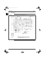
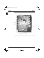
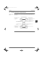
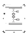
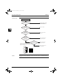
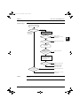
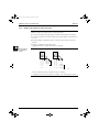
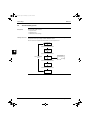
3.2
ESIE05-03
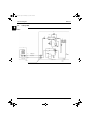
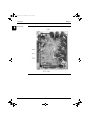
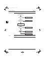
Pair System
RZQ71
6
14a
14a
8
10
14a
7
14a
5a
3
9
17
20
7
16
4
15
16
11
14a
1a
8
Gas piping
1a
5
Liquid piping
Indoor unit
10
1a
4
12
Outdoor unit
Heating
Cooling
2b & 3
1–22
Part 1 – System Outline
ESIE05-03.book Page 23 Wednesday, April 6, 2005 4:09 PM
ESIE05-03
Functional Diagrams
1
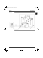
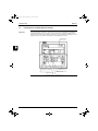
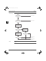
RZQ100~140
14a
8
14a
14a
14a
14a
7
17
6
9
20
3
5a
10
7
15
1a
8
Gas piping
1a
Indoor unit
12
11
Liquid piping
4
16
8
10
1a
4
Outdoor unit
5
Heating
Cooling
2b & 3
Part 1 – System Outline
1–23
ESIE05-03.book Page 24 Wednesday, April 6, 2005 4:09 PM
Functional Diagrams
11
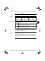
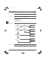
3.3
ESIE05-03
Twin System
RZQ71
6
14a
14a
7
8
3
8
7
10
14a
5a
14a
1a
9
17
1a
20
Indoor unit
16
4
15
16
11
7
14a
Liquid piping
10
19
Gas piping
1a
4
5
8
1a
1a
Indoor unit
1–24
12
Outdoor unit
Heating
Cooling
2b & 3
NOTE: The pipes between the branch and the indoor units
should have the same size as the indoor connections.
Part 1 – System Outline
ESIE05-03.book Page 25 Wednesday, April 6, 2005 4:09 PM
ESIE05-03
Functional Diagrams
1
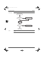
RZQ100~140
14a
14a
7
14a
8
7
14a
14a
17
6
8
1a
9
20
1a
5a
3
10
Indoor unit
15
8
11
12
16
4
7
Liquid piping
10
19
Gas piping 1a
4
8
Outdoor unit
1a
1a
Indoor unit
Part 1 – System Outline
Heating
Cooling
2b & 3
5
NOTE: The pipes between the branch and the indoor units
should have the same size as the indoor connections.
1–25
ESIE05-03.book Page 26 Wednesday, April 6, 2005 4:09 PM
Functional Diagrams
11
3.4
ESIE05-03
Triple System
RZQ100~140
7
14a
14a
14a
14a
14a
8
8
Indoor unit
3
2b & 3
1a
7
17
1a
6
9
7
20
5a
10
Liquid piping
4
8
1a
15
1a
1a
8
12
11
16
Gas piping
Indoor unit
1a
10
7
19
4
5
Outdoor unit
8
Indoor unit
1–26
1a
1a
Heating
Cooling
NOTE: The pipes between the branch and the indoor units
should have the same size as the indoor connections.
Part 1 – System Outline
ESIE05-03.book Page 27 Wednesday, April 6, 2005 4:09 PM
ESIE05-03
3.5
Functional Diagrams
Double Twin System
1
RZQ100~140
7
Indoor unit
14a
8
1a
8
14a
8
14a
14a
14a
7
1a
17
9
Indoor unit
8
3
6
7
20
5a
10
1a
15
Liquid piping
1a
1a
8
19
7
8
Indoor unit
Gas piping
11
12
16
4
1a
10
4
1a
Outdoor unit
Heating
Cooling
1a
7
Indoor unit
8
1a
5
2b & 3
NOTE: The pipes between the branch and the indoor units
should have the same size as the indoor connections.
1a
Part 1 – System Outline
1–27
ESIE05-03.book Page 28 Wednesday, April 6, 2005 4:09 PM
Functional Diagrams
11
3.6
ESIE05-03
Pipe Connection Diameters
Outdoor units
The table below contains the refrigerant pipe connection diameters.
Model
RZQ71B8V3B
∅ Gas pipe (flare)
∅ Liquid pipe (flare)
15.9 mm
9.52 mm
RZQ100B8V3B/B7W1B
RZQ125B8V3B/B7W1B
RZQ140B7W1B
3
4
5
1–28
Part 1 – System Outline
ESIE05-03.book Page 29 Wednesday, April 6, 2005 4:09 PM
ESIE05-03
3.7
Functional Diagrams
Re-using Existing Field Piping
Introduction
1
When installing a system using an RZQ outdoor unit, existing or pre-installed piping can be used
according to below specified conditions.
In all circumstances where these conditions can not be fully met, new piping has to be installed.
How to re-use
existing piping?
Check the existing
pipe size.
Non-standard
size
Standard size
Check the existing pipe size and thickness
referring to the "(1) SELECTION OF PIPING
on page
1–30.
MATERIAL" (on
the next
page).
Check the following item in
"(2) REFRIGERANT PIPE SIZE" and
"(3) ALLOWABLE PIPE LENGTH AND
on the
page
1–31.
HEIGHT DIFFERENCE" (on
next
page)
Not listed
Beyond
allowable
length range
See if the length requirements for re-using
the existing piping are as specified.
All satisfactory
See if the reduction of cooling capacity
may cause any problem.
Reuse
of
No tolerance
for capacity
reduction
existing
pipe
not
allowed
Check the existing pipe length.
Longer than 50 m
3
4
50 m or less
See if the already installed air conditioner can operate and perform a
pump-down operation.
Operation not possible
Pump-down operation
not possible
5
Both operation and pump-down are possible
After 30 minutes of cooling operation, proceed with pump-down operation
without interruption.
Remove the existing air conditioner.
Check the compressor (of the existing air conditioner) for fault records.
Exist
None
See if the contamination inside the existing pipe is acceptable.
NO
OK
Rework the flare. (For R410A: See table on page 1–33. )
Use the supplied flare nut.
Existing piping work for new air conditioner
Notes:
Oil contamination can be checked using the Daikin “Oil Checker Card”.
Caution:
P
If copper piping is corroded, existing piping re-use is not allowed.
P
Single side thermal insulation is not allowed for re-use.
P
See further notes in this section for Twin, Triple and Double Twin applications.
Part 1 – System Outline
1–29
ESIE05-03.book Page 30 Wednesday, April 6, 2005 4:09 PM
Functional Diagrams
Do not allow anything other than the designated refrigerant to get mixed into the freezing cycle (air,
moisture,... ). If any refrigerant gas leaks while working on the unit, ventilate the room thoroughly
immediately.
P
Use R410A only when adding refrigerant.
P
Make sure all installation tools are designed for use on R410A refrigerant to withstand the
pressure.
P
Vacuum pump. Use a 2-stage vacuum pump with a non-return valve. Make sure the pump oil does
not flow oppositely into the new system while the pump is not working. Use a vacuum pump which
can evacuate to -100.7 kPa (5 Torr, -755 mmHg).
P
Check welded connections for gas leaks, if the local piping has welded connections.
P
Main piping (L1) can be re-used, size up & size down is allowed (see further in this section for
restrictions).
P
Re-use of branch piping is not allowed.
P
Branch piping (L2~L7) can be re-used, but standard pipe size only.
Pair
4
Triple
Double twin
L2
Selection of piping
material
L1
L3
L1
L4
L5
L1
L3
L7
H1
L1
L4
L6
H1
L3
H2
L2
L2
H1
5
Twin
H2
Notes for Twin,
Triple and Double
Twin
P
H1
3
Precautions on
refrigerant piping
H2
11
ESIE05-03
P
Construction material: phosphoric acid deoxidized seamless copper for refrigerant.
P
Temper grade: use piping with temper grade in function of the pipe diameter as listed in table
below.
P
The pipe thickness of the refrigerant piping should comply with relevant local and national
regulations. The minimal pipe thickness for R410A piping must be in accordance with the table
below.
Pipe φ
Temper grade of piping material
Minimal thickness t(mm)
6.4 / 9.5 / 12.7
Ο
0.80
15.9
Ο
1
19.1
1/2H
1
Ο = Annealed
1/2H = Half hard
1–30
Part 1 – System Outline
ESIE05-03.book Page 31 Wednesday, April 6, 2005 4:09 PM
ESIE05-03
Refrigerant pipe
size
Functional Diagrams
P
1
Pipe size down and pipe size up is available for main piping (L1) only.
Refrigerant pipe size
Gas pipe
Model
Size-down
RZQ71
φ 12.7
RZQ100~140
––
Standard size
φ 15.9
Size-up
––
φ 19.1
Liquid pipe
Model
RZQ71~140
P
Size-down
Standard size
Size-up
φ 6.4
φ 9.5
φ 12.7
Not using the standard pipe size may result in capacity decrease. It is up to the installer to judge
on this phenomenon carefully in function of the complete installation.
3
4
5
Part 1 – System Outline
1–31
ESIE05-03.book Page 32 Wednesday, April 6, 2005 4:09 PM
Functional Diagrams
11
Allowable pipe
length and heigth
difference
ESIE05-03
When re-using existing piping, refer to below table for allowable piping length and heigth difference
(figures in brackets are equivalent lengths).
Model RZQ
Liquid pipe
size
71
100
125 & 140
Maximum allowable piping length (*)
Pair: L1
Twin and triple: L1 + L2
Double twin: L1 + L2 + L4
3
size-down
10 m (15 m)
standard
50 m (70 m)
50 m (70 m)
50 m (70 m)
size-up
25 m (35 m)
35 m (45 m)
35 m (45 m)
Maximum total one-way piping length
Twin: L1 + L2 + L3
Triple: L1 + L2 + L3 + L4
50 m
––
Double twin:
L1 + L2 + L3 + L4 + L5 + L6 + L7
4
50 m
––
50 m
––
Maximum branch piping length
Twin: L2
Double twin: L2 + L4
––
20 m
Maximum difference between branch lengths
5
10 m
Twin: L2 - L3
Triple: L2 - L4
––
Double twin: L2 - L3, L4 - L5,
L6 - L7, (L2 + L4) - (L3 + L7)
––
10 m
10 m
––
Maximum heigth between indoor and outdoor
All: H1
––
30 m
––
0.5 m
size-down
10 m
standard
30 m
size-up
15 m
Maximum heigth between indoors
Twin, triple and double twin: H2
Chargeless length
All:
L1 + L2 + L3 + L4 + L5 + L6 + L7
1–32
Part 1 – System Outline
ESIE05-03.book Page 33 Wednesday, April 6, 2005 4:09 PM
ESIE05-03
Caution for flare
connections
Functional Diagrams
P
Refer to below table for correct flare dimensions and tightening torques. Too high tightening force
may cause refrigerant leak because of flare cracking:
Flare nut
tightening torque
A dimensions for
processing flares (mm)
Ø 6.4
14.2~17.2 N·m
(144~176 kgf·cm)
8.7~9.1
Ø 9.5
32.7~39.9 N·m
(333~407 kgf·cm)
12.8~13.2
Ø 12.7
49.5~60.3 N·m
(504~616 kgf·cm)
16.2~16.6
Ø 15.9
61.8~75.4 N·m
(630~770 kgf·cm)
19.3~19.7
Ø 19.1
97.2~118.6 N·m
(989.8~1208 kgf·cm)
23.6~24.0
Piping size
P
1
Flare shape
90°±0.5
45 ±
° 2
A
R=0.4~0.8
3
When connecting the flare nut, apply refrigerating machine oil to the flare (inside and outside) and
first screw the nut 3 or 4 turns by hand. Coat the indicated surfaces using ether or ester oil:
4
P
Part 1 – System Outline
After completing the installation, carry out an inspection of the piping connections by pressure test
using nitrogen.
1–33
5
ESIE05-03.book Page 34 Wednesday, April 6, 2005 4:09 PM
Functional Diagrams
ESIE05-03
11
3
4
5
1–34
Part 1 – System Outline
ESIE05-03
3.8
Components
The table below contains the different components of the functional diagrams.
No.
Component
Function / remark
1a
Flare connection
See pipe connection diameter.
2a
Liquid stop valve
The liquid stop valve is used as shut-off valve in case of a pump-down.
2b
Liquid stop valve
with service port
3
Gas stop valve with
service port
The gas stop valve is used as shut-off valve in case of a pump-down.
4
Compressor
The compressor can restart after 3 min from last stop.
5a
Capillary tube
The capillary tube allows pressure equalization during a compressor OFF-cycle.
5b
The capillary tube expands the liquid to enable evaporation in the evaporator.
6
Electronic expansion valve
The expansion valve expands the liquid to enable evaporation in the evaporator. The opening
degree is controlled to obtain the optimum discharge temperature.
7
Heat exchanger
The heat exchanger is of the multi louvre fin type. Hi-X -tubes and coated waffle louvre fins are
used.
8
Filter
The filter is used to collect impurities, which may enter the system during installation and is also
used to avoid blockage of the capillaries and other fine mechanical parts of the unit.
9
Liquid receiver
The liquid receiver is used to make sure only completely liquefied refrigerant is sent to the expansion valve. It is also used as a container in which surplus refrigerant is stored.
10
Check valve with
service port
The check valve allows you to connect a gauge.
11
Low-pressure sensor (RZQ71)
The low pressure sensor is used to control the unit's actuators (expansion valve, frequency,...)
Low-pressure switch
(RZQ100~140)
The low-pressure switch stops the operation of the unit when the pressure becomes abnormally
low.
12
High-pressure
switch
The high-pressure switch stops the operation of the unit when the pressure becomes abnormally
high.
13
Propeller fan and fan
motor
The propeller fan creates air displacement across the heat exhanger.
14a
One-way valve
The one-way valve is used to force the refrigerant liquid to flow through the receiver and the
expansion valve in the same direction both in cooling and heating.
14b
15
The one-way valve is used to release overpressure in the liquid receiver during stand-still.
4-way valve
The 4-way valve is used to select refrigerant flow in cooling or heating mode.
(reversing solenoid
valve)
When the 4-way valve switches from ON to OFF, a timer starts counting up to 150 as soon as the
cooling or defrosting operation is stopped. This delay time is to eliminate the switching sound.
16
Muffler
The muffler is used to absorb the refrigerant noise from the compressor.
17
Solenoid valve
P
Y1S: Capacity control solenoid valve
P
Y3S: Liquid injection solenoid valve
P
SV: Solenoid valve (Purge liquid receiver)
P
R1T: Air thermistor
P
R2T: Coil thermistor
P
R3T: Discharge pipe thermistor
18
Part 1 – System Outline
Part 1
Piping Components
Thermistor
19
Branch pipe
20
Strainer
1–35
ESIE05-03
1–36
Part 1 – System Outline
ESIE05-03.book Page 37 Wednesday, April 6, 2005 4:09 PM
ESIE05-03
Switch Box Layout
Part 1
4
Switch Box Layout
4.1
What Is in This Chapter?
Introduction
This chapter shows the switch box components.
Outdoor units
This chapter contains the following switch box layouts:
1
3
Switch box layout
See page
4.2–RZQ71B8V3B
1–38
4.3–RZQ100~125B8V3B
1–39
4.4–RZQ100~140B7W1B
1–40
4
5
Part 1 – System Outline
1–37
ESIE05-03.book Page 38 Wednesday, April 6, 2005 4:09 PM
Switch Box Layout
11
4.2
ESIE05-03
RZQ71B8V3B
The illustration below shows the switch box layout:
3
4
5
1–38
Item
Description
A1P
Printed circuit board (control)
A2P
Printed circuit board (inverter)
X1M
Terminal strip
Part 1 – System Outline
ESIE05-03.book Page 39 Wednesday, April 6, 2005 4:09 PM
ESIE05-03
4.3
Switch Box Layout
RZQ100~125B8V3B
1
The illustration below shows the switch box layout:
3
4
5
Part 1 – System Outline
Item
Description
A1P
Printed circuit board (control)
A2P
Printed circuit board (inverter)
X1M
Terminal strip
1–39
ESIE05-03.book Page 40 Wednesday, April 6, 2005 4:09 PM
Switch Box Layout
11
4.4
ESIE05-03
RZQ100~140B7W1B
The illustration below shows the switch box layout:
3
4
5
1–40
Item
Description
A1P
Printed circuit board (control)
A2P
Printed circuit board (inverter)
X1M
Terminal strip
Part 1 – System Outline
ESIE05-03.book Page 41 Wednesday, April 6, 2005 4:09 PM
ESIE05-03
Wiring Diagrams
Part 1
5
Wiring Diagrams
5.1
What Is in This Chapter?
Introduction
This chapter contains the wiring diagrams of the outdoor and indoor units.
Outdoor units:
This chapter contains the following wiring diagrams:
1
3
Wiring diagram
See page
5.2–RZQ71B8V3B
1–42
5.3–RZQ100~125B8V3B
1–44
5.4–RZQ100~140B7W1B
1–46
4
5
Part 1 – System Outline
1–41
ESIE05-03.book Page 42 Wednesday, April 6, 2005 4:09 PM
Wiring Diagrams
11
5.2
ESIE05-03
RZQ71B8V3B
Wiring diagram
The illustration below shows the wiring diagram of the unit.
71 CLASS
indoor
outdoor
NOTE 1
3
4
ON
OFF
5
EL.COMPO.ASSY FRONT
BLK
BLU
BRN
GRN
ORG
RED
WHT
YLW
:
:
:
:
:
:
:
:
BLACK
BLUE
BROWN
GREEN
ORANGE
RED
WHITE
YELLOW
L : LIVE
N : NEUTRAL
1–42
VIEW A
CONNECTOR
PROTECTIVE EARTH (SCREW)
TERMINAL
TERMINAL
FIELD WIRING
RELAY CONNECTOR
NOTES :
1. REFER TO THE OPTION MANUAL, FOR CONNECTING WIRING TO X6A.
2. CONFIRM THE METHOD OF SETTING THE SELECTOR SWITCHES (DS1)
BY SERVICE MANUAL. WHEN UNIT IS SHIPPED BY FACTORY
ALL SWITCHES ARE SET TO BE OFF.
Part 1 – System Outline
ESIE05-03.book Page 43 Wednesday, April 6, 2005 4:09 PM
ESIE05-03
Wiring Diagrams
A1P
Printed circuit board
R1T
Thermistor (Air)
A2P
Printed circuit board (INV.)
R2T
Thermistor (Coil)
BS1
Push button switch
(Forced defrost-pump down)
R3T
Thermistor (Discharge pipe)
R4T
Thermistor (Suction pipe)
C1, C2, C3
Capacitor
R5T
Thermistor (Power module)
DS1
Dip switch
RC
Signal receiver circuit
F1U
Fuse (T 6.3/250V)
S1PH
Pressure switch (High)
HAP (A1P, A2P)
Light emitting diode
(Service monitor green)
S1NPL
Pressure sensor (Low)
TC
Signal transmission circuit
Light emitting diode
(Service monitor red)
V1R
Power module
V2R, V3R
Diode module
H1P (A1P)
K1M (A2P)
Magnetic contactor
V1T
IGBT
K1R (A1P)
Magnetic relay (Y1S)
X6A
Connector (Option)
K2R (A1P)
Magnetic relay (Y2S)
X1M
Terminal strip
K2R (A2P)
Magnetic relay
Y1E
Expansion valve
L1R
Reactor
Y1S
4-way valve
M1C
Motor compressor
Y2S
Solenoid valve
M1F
Motor fan
Noise filter
PS
Power supply
Z1C, Z2C, Z3C,
Z4C
Q1DI
Earth leakage breaker (30mA)
Z1F
Noise filter (with surge absorber)
R1, R2
Resistor
1
3
4
5
Part 1 – System Outline
1–43
ESIE05-03.book Page 44 Wednesday, April 6, 2005 4:09 PM
Wiring Diagrams
11
5.3
ESIE05-03
RZQ100~125B8V3B
Wiring diagram
The illustration below shows the wiring diagram of the unit.
100-125 CLASS
indoor
outdoor
3
NOTE 1
4
ON
OFF
5
EL.COMPO.ASSY FRONT
L : LIVE
N : NEUTRAL
FIELD WIRING
PROTECTIVE EARTH (SCREW)
TERMINAL
TERMINAL
CONNECTOR
RELAY CONNECTOR
VIEW A
BLK
BLU
GRN
RED
WHT
YLW
:
:
:
:
:
:
REACTOR BOX
BLACK
BLUE
GREEN
RED
WHITE
YELLOW
NOTES :
1. REFER TO THE OPTION MANUAL, FOR CONNECTING WIRING TO X6A.
2. CONFIRM THE METHOD OF SETTING THE SELECTOR SWITCHES (DS1)
BY SERVICE MANUAL. WHEN UNIT IS SHIPPED BY FACTORY
ALL SWITCHESARE SET TO BE OFF.
1–44
Part 1 – System Outline
ESIE05-03.book Page 45 Wednesday, April 6, 2005 4:09 PM
ESIE05-03
Wiring Diagrams
A1P
Printed circuit board
Q1DI
Earth leakage breaker (30mA)
A2P
Printed circuit board (INV.)
R1, R2
Resistor
BS1
Push button switch
(Forced defrost-pump down)
R1T
Thermistor (Air)
R2T
Thermistor (Coil)
C1, C2, C3
Capacitor
R3T
Thermistor (Discharge pipe)
DS1
Dip switch
R4T
Thermistor (Suction pipe)
E1HC
Crankcase heater
R5T
Thermistor (Power module)
F1U
Fuse (T 6.3/250V)
RC
Signal receiver circuit
F2U
Fuse
S1PH
Pressure switch (High)
F3U
Fuse (B 5A/250V)
S1PL
Pressure switch (Low)
HAP (A1P, A2P)
Light emitting diode
(Service monitor green)
TC
Signal transmission circuit
V1R
Power module
H1P (A1P)
Light emitting diode
(Service monitor red)
V2R, V3R
Diode module
V1T
IGBT
K1M (A1P)
Magnetic contactor
X6A
Connector (Option)
K1R (A1P)
Magnetic relay (Y1S)
X1M
Terminal strip
K2R (A1P)
Magnetic relay
Y1E
Expansion valve
K3R (A1P)
Magnetic relay (E1HC)
Y1S
4-way valve
K4R (A1P)
Magnetic relay (Y2S)
Y2S
Solenoid valve
L1R
Reactor
Motor compressor
Z1C, Z2C, Z3C,
Z4C
Noise filter
M1C
M1F, M2F
Motor fan
Z1F
Noise filter (with surge absorber)
PS
Power supply
1
3
4
5
Part 1 – System Outline
1–45
ESIE05-03.book Page 46 Wednesday, April 6, 2005 4:09 PM
Wiring Diagrams
11
5.4
ESIE05-03
RZQ100~140B7W1B
Wiring diagram
The illustration below shows the wiring diagram of the unit.
100-125-140 CLASS
indoor
outdoor
NOTE 1
3
ON
OFF
4
5
EL.COMPO.ASSY FRONT
L : LIVE
N : NEUTRAL
FIELD WIRING
PROTECTIVE EARTH (SCREW)
TERMINAL
TERMINAL
CONNECTOR
RELAY CONNECTOR
VIEW A
BLK
BLU
BRN
GRN
ORG
RED
WHT
YLW
:
:
:
:
:
:
:
:
REACTOR BOX
BLACK
BLUE
BROWN
GREEN
ORANGE
RED
WHITE
YELLOW
NOTES :
1. REFER TO THE OPTION MANUAL, FOR CONNECTING WIRING TO X6A.
2. CONFIRM THE METHOD OF SETTING THE SELECTOR SWITCHES (DS1)
BY SERVICE MANUAL. WHEN UNIT IS SHIPPED BY FACTORY
ALL SWITCHES ARE SET TO BE OFF.
1–46
Part 1 – System Outline
ESIE05-03.book Page 47 Wednesday, April 6, 2005 4:09 PM
ESIE05-03
Wiring Diagrams
A1P
Printed circuit board
PS
Power supply
A2P
Printed circuit board (INV.)
Q1DI
Earth leakage breaker (30mA)
BS1
Push button switch
(Forced defrost-pump down)
R1 (A1P)
Resistor
R1, R2 (A2P)
Resistor
C1, C2, C3
Capacitor
R1T
Thermistor (Air)
DS1
Dip switch
R2T
Thermistor (Coil)
E1HC
Crankcase heater
R3T
Thermistor (Discharge pipe)
F1U (A1P)
Fuse (T 6.3/250V)
R4T
Thermistor (Suction pipe)
F2U
Fuse (T 6.3/250V)
R5T
Thermistor (Power module)
F3U
Fuse (B 5A/250V)
RC
Signal receiver circuit
F4U
Fuse (B 10A/250V)
S1PH
Pressure switch (High)
F1U (A2P)
Fuse
S1PL
Pressure switch (Low)
HAP (A1P, A2P)
Light emitting diode
(Service monitor green)
TC
Signal transmission circuit
V1R
Power module
H1P (A1P)
Light emitting diode
(Service monitor red)
V2R, V3R
Diode module
X6A
Connector (Option)
K1M (A1P)
Magnetic contactor
X1M
Terminal strip
K1R (A1P)
Magnetic relay (Y1S)
Y1E
Expansion valve
K2R (A1P)
Magnetic relay (Y2S)
Y1S
4-way valve
K3R (A1P)
Magnetic relay (E1HC)
Y2S
Solenoid valve
K4R, K5R
Magnetic relay
Noise filter
L1R
Reactor
Z1C, Z2C, Z3C,
Z4C, Z5C
M1C
Motor compressor
Z1F
Noise filter (with surge absorber)
M1F, M2F
Motor fan
Z2F
Noise filter
1
3
4
5
Part 1 – System Outline
1–47
ESIE05-03.book Page 48 Wednesday, April 6, 2005 4:09 PM
Wiring Diagrams
ESIE05-03
11
3
4
5
1–48
Part 1 – System Outline
ESIE05-03.book Page 49 Wednesday, April 6, 2005 4:09 PM
ESIE05-03
PCB Layout
Part 1
6
PCB Layout
6.1
What Is in This Chapter?
Introduction
Outdoor units
This chapter contains the following information:
P
It describes which unit uses which PCB types
P
It shows the PCB connectors.
1
3
This chapter contains the following PCB layouts:
PCB layout
See page
6.2–RZQ71B8V3B
1–50
6.3–RZQ100~125B8V3B
1–54
6.4–RZQ100~140B7W1B
1–58
4
5
Part 1 – System Outline
1–49
ESIE05-03.book Page 50 Wednesday, April 6, 2005 4:09 PM
PCB Layout
11
6.2
ESIE05-03
RZQ71B8V3B
Control PCB
The illustration below shows the PCB connectors.
3
4
5
1–50
Part 1 – System Outline
ESIE05-03.book Page 51 Wednesday, April 6, 2005 4:09 PM
ESIE05-03
Connectors
PCB Layout
1
The table below describes the PCB connectors.
Connector
Connected to
Description
X1A
X1M
Terminal strip connector
X3A
X205A (on
inverter PCB)
X6A
For optional PCB KRP58M51
X12A
Y1E
Expansion valve
X17A
R3T
Discharge pipe thermistor
X18A
R4T
Suction pipe thermistor
X19A
R2T
Coil thermistor
X20A
R1T
Air thermistor
X22A
Y1S
4-way valve
X26A
Connector for spare part adaptor
X28A
Y2S
Solenoid valve
X64A
S1NPL
Low pressure sensor
X77A
3
4
For optional PCB KRP58M51
5
Part 1 – System Outline
1–51
ESIE05-03.book Page 52 Wednesday, April 6, 2005 4:09 PM
PCB Layout
11
Inverter PCB
ESIE05-03
The illustration below shows the PCB connectors.
3
4
5
1–52
Part 1 – System Outline
ESIE05-03.book Page 53 Wednesday, April 6, 2005 4:09 PM
ESIE05-03
Connectors
PCB Layout
1
The table below describes the PCB connectors.
Connector
Connected to
Description
X60A
S1PH
High pressure switch
X201A
M1C
Compressor motor
X205A
X3A on control
PCB
X206A
M1F
Fan motor
X207A
R5T
Power module thermistor
3
4
5
Part 1 – System Outline
1–53
ESIE05-03.book Page 54 Wednesday, April 6, 2005 4:09 PM
PCB Layout
11
6.3
ESIE05-03
RZQ100~125B8V3B
Control PCB
The illustration below shows the PCB connectors.
3
4
5
1–54
Part 1 – System Outline
ESIE05-03.book Page 55 Wednesday, April 6, 2005 4:09 PM
ESIE05-03
Connectors
PCB Layout
Connector
Connected to
Description
X3A
X1M
Terminal strip connector
X4A
X104A (on
inverter PCB)
X6A
Part 1 – System Outline
1
The table below describes the PCB connectors.
For optional PCB KRP58M51
X8A
X108A (on
inverter PCB)
X11A
R1T
Air thermistor
X12A
R2T
Coil thermistor
X13A
R3T
Discharge pipe thermistor
X14A
R4T
Suction pipe thermistor
X21A
Y1E
Expansion valve
X22A
Y1S
4-way valve
X23A
Y2S
Solenoid valve
X24A
E1HC
Crankcase heater
X31A
S1PL
Low pressure switch
X32A
S1PH
High pressure switch
X51A
Connector for spare parts adaptor
X77A
For optional PCB KRP58M51
3
4
5
1–55
ESIE05-03.book Page 56 Wednesday, April 6, 2005 4:09 PM
PCB Layout
11
Inverter PCB
ESIE05-03
The illustration below shows the PCB connectors.
3
4
5
1–56
Part 1 – System Outline
ESIE05-03.book Page 57 Wednesday, April 6, 2005 4:09 PM
ESIE05-03
Connectors
PCB Layout
1
The table below describes the PCB connectors.
Connector
Connected to
Description
X102A
M1C
Compressor motor
X104A
X4A (on control
PCB)
X106A
M1F
Fan motor
X107A
M2F
Fan motor
X108A
X8A (on control
PCB)
X111A
R5T
Power module thermistor
3
4
5
Part 1 – System Outline
1–57
ESIE05-03.book Page 58 Wednesday, April 6, 2005 4:09 PM
PCB Layout
11
6.4
ESIE05-03
RZQ100~140B7W1B
Control PCB
The illustration below shows the PCB connectors.
3
4
5
1–58
Part 1 – System Outline
ESIE05-03.book Page 59 Wednesday, April 6, 2005 4:09 PM
ESIE05-03
Connectors
PCB Layout
Connector
Connected to
Description
X1A
V2R
Diode module
X3A
X1M
Terminal strip connector
X4A
X104A (on
inverter PCB)
X6A
Part 1 – System Outline
1
The table below describes the PCB connectors.
For optional PCB KRP58M51
X8A
X108A (on
inverter PCB)
X9A
X109A (on
inverter PCB)
X11A
R1T
Air thermistor
X12A
R2T
Coil thermistor
X13A
R3T
Discharge pipe thermistor
X14A
R4T
Suction pipe thermistor
X21A
Y1E
Expansion valve
X22A
Y1S
4-way valve
X23A
Y2S
Solenoid valve
X24A
E1HC
Crankcase heater
X31A
S1PL
Low pressure switch
X32A
S1PH
High pressure switch
X51A
Connector for spare parts adaptor
X77A
For optional PCB KRP58M51
3
4
5
1–59
ESIE05-03.book Page 60 Wednesday, April 6, 2005 4:09 PM
PCB Layout
11
Inverter PCB
ESIE05-03
The illustration below shows the PCB connectors.
3
4
5
1–60
Part 1 – System Outline
ESIE05-03.book Page 61 Wednesday, April 6, 2005 4:09 PM
ESIE05-03
Connectors
PCB Layout
1
The table below describes the PCB connectors.
Connector
Connected to
Description
X102A
M1C
Compressor motor
X104A
X4A (on control
PCB)
X106A
M1F
Fan motor
X107A
M2F
Fan motor
X108A
X8A (on control
PCB)
X109A
X9A (on control
PCB)
X111A
R5T
3
Power module thermistor
4
5
Part 1 – System Outline
1–61
ESIE05-03.book Page 62 Wednesday, April 6, 2005 4:09 PM
PCB Layout
ESIE05-03
11
3
4
5
1–62
Part 1 – System Outline
ESIE05-03.book Page 1 Wednesday, April 6, 2005 4:09 PM
ESIE05-03
4
Part 2
Functional Description
What is in this part?
This part contains information on the functions used to control the system. Understanding these
functions is vital when diagnosing a malfunction that is related to the functional control.
Overview
This part contains the following chapters:
2
3
Chapter
See page
1–General Functionality
2–3
2–Indoor Unit Functional Concept
2–27
3–Outdoor Unit Functional Concept
2–37
4
5
Part 2 – Functional Description
2–1
ESIE05-03.book Page 2 Wednesday, April 6, 2005 4:09 PM
ESIE05-03
1
2
3
5
2–2
Part 2 – Functional Description
ESIE05-03.book Page 3 Wednesday, April 6, 2005 4:09 PM
ESIE05-03
General Functionality
Part 2
1
1
General Functionality
2
1.1
What Is in This Chapter?
Introduction
This chapter will explain all functions not related to the compressor frequency control, outdoor unit fan
control and expansion valve control. These functions have been programmed to ensure the unit's
reliability and lifetime, enable the operation in case of malfunction, or increase the customer's comfort.
Overview
This chapter contains the following topics:
Topic
See page
1.2–Functions of Thermistors
2–4
1.3–Forced Operating Mode (Emergency Operation)
2–6
1.4–Outdoor Unit Identification Function
2–8
1.5–Simulated Operation Function
2–9
1.6–Restart Standby
2–10
1.7–Automatic Restart
2–11
1.8–Using Conditions for Remote Controller Thermostat
2–12
1.9–Forced Thermostat OFF
2–14
1.10–Test Run Control
2–15
1.11–4-way Valve Control
2–16
1.12–Pump Down Residual Operation
2–17
1.13–Pump Down Operation
2–18
1.14–Defrost Operation
2–19
1.15–Freeze Prevention Function
2–22
1.16–PMV Control
2–23
1.17–Preheating Operation Control
2–24
1.18–Crankcase Heater Control
2–25
Part 2 – Functional Description
3
4
5
2–3
ESIE05-03.book Page 4 Wednesday, April 6, 2005 4:09 PM
General Functionality
1
1.2
ESIE05-03
Functions of Thermistors
Locating the
thermistors
2
햴
3
햵
햲
햳
햷
햶
4
Remark
5
Sensor R3T on indoor coil of FCQ35~60B7V1, FFQ35~60B7V1B, FBQ35~60B7V1 &
FHQ35~60BUV1B is not used when the indoor units are connected to RZQ outdoor units.
Functions of the
thermistors
Thermistor
1
Location
Indoor
heat
exchanger
Wiring
symbol
Mode
Function
R2T
Cooling
P
Compressor frequency control (target Te)
P
Inverter current protection control
P
Freeze-up control
P
Compressor frequency control (target Tc)
P
Inverter current protection control
P
Hot start control
P
Peak cut-off
P
Thermostat control
P
PMV control
P
General frequency control
P
Thermostat control
P
PMV control
P
General frequency control
Cooling
P
Inverter current protection control
Heating
P
Inverter current protection control
P
Defrost control
Heating
2
Indoor air
return
R1T
Cooling
Heating
3
2–4
Outdoor
heat
exchanger
R2T
Part 2 – Functional Description
ESIE05-03.book Page 5 Wednesday, April 6, 2005 4:09 PM
ESIE05-03
General Functionality
Thermistor
4
Location
Outdoor
ambient
Wiring
symbol
Mode
Function
R1T
Cooling
P
Outdoor fan speed control
P
PMV control
P
Pressure difference control
P
Overall current protection control
P
Preheating operation control (RZQ71)
P
Defrost control
P
PMV control
P
Forced thermostat OFF
P
Overall current protection control
P
Preheating operation control (RZQ71)
P
Discharge superheat control
P
Expansion valve control
P
Crankcase heater / preheating control
P
Expansion valve control
P
Crankcase heater / preheating control
Cooling
P
Expansion valve control (SH control)
Heating
P
Expansion valve control (SH control)
P
Suction pipe superheat protection control
P
Outdoor fan speed control
P
Inverter fin temperature control
P
Pressure difference control
P
Inverter fin temperature control
Heating
5
Discharge
pipe
R3T
Cooling
Heating
6
7
Suction
pipe
Inverter
power
module
R4T
R5T
Cooling
Heating
Part 2 – Functional Description
1
2
3
4
5
2–5
ESIE05-03.book Page 6 Wednesday, April 6, 2005 4:09 PM
General Functionality
1
1.3
ESIE05-03
Forced Operating Mode (Emergency Operation)
Purpose
The table below describes the purpose of the forced operating mode.
If...
2
3
Starting conditions
Then...
P
R/C is defective
P
Indoor PCB is defective
P
Outdoor PCB is defective
Forced operating mode can be used to go to cooling or heating. In forced operating mode, the compressor is forced to
operate until the defective indoor or outdoor PCB is back
online.
You can operate the system manually by changing the emergency switch on the indoor and outdoor
PCB from "normal" to "emergency". When the system is operating in "emergency" it can not control
the room temperature.
Both the indoor and outdoor unit must be set to "emergency" while the power is off.
4
Ending conditions
You can end the emergency operation by changing the "emergency" switch back to "normal" while the
power is OFF.
Emergency
operation
Below table explains what will happen when the switch is set to "emergency":
5
Changing the switch to "emergency" for the…
Switches ON the…
Indoor unit
P
Indoor fan§
P
Drain pump
P
Compressor§
P
Outdoor fan(s)
Outdoor unit
How to set
Emergency
Operation
To set emergency operation, proceed as follows:
Step
Action
1
Turn OFF the power.
2
Switch ON the emergency switch (SS1) on the indoor PCB.
Normal
Emergency
2–6
Part 2 – Functional Description
ESIE05-03.book Page 7 Wednesday, April 6, 2005 4:09 PM
ESIE05-03
General Functionality
Step
Action
3
Switch ON the emergency switch on the outdoor PCB.
1
EMERGENCY
ON
COOL
2
1
OFF
4
2
3
4
HEAT
Set the emergency switch on the outdoor PCB to the forced mode you prefer (Cooling or
Heating).
3
EMERGENCY
ON
COOL
4
1
OFF
5
2
3
4
HEAT
5
Turn ON the power supply.
Active components
Additional info
Component
Forced cooling
Forced heating
Forced defrosting
Compressor
ON
ON
ON
4-way valve
OFF
ON
OFF
Outdoor unit fan
H fan speed
H fan speed
OFF
Indoor unit fan
H fan speed
H fan speed
H fan speed
Drain pump
ON
ON
ON
P
During emergency operation, do not attempt to operate the equipment from the remote controller.
The remote controller shows "88" while the emergency operation is active on the indoor unit
P
If a safety device is activated during emergency, all actuators are turned OFF
P
In cooling, the unit runs for 20min and then stops for 10min in order to avoid freeze-up of the indoor
coil.
P
In heating, defrost is activated for 3 minutes once every hour.
P
Emergency operation can not be carried out when the PCB board itself is defective.
P
Be sure to set the emergency switch on both the outdoor and indoor unit.
P
The unit will not regulate the temperature during emergency operation.
P
Change the position of the emergency switch only when the power is turned off.
Part 2 – Functional Description
2–7
ESIE05-03.book Page 8 Wednesday, April 6, 2005 4:09 PM
General Functionality
1
2
1.4
ESIE05-03
Outdoor Unit Identification Function
Purpose
The purpose of the outdoor unit identification function is to enable the indoor unit to automatically
determine which operating mode has to be set in function of the type of connected outdoor unit (c/o or
h/p).
Operating modes
The possible operating modes are:
Outdoor unit
Operating modes
h/p
P
Fan
P
Cooling
P
Dry keep
P
Heating
P
Fan
P
Cooling
P
Dry keep
3
c/o
4
Used input
5
The outdoor unit identification function uses the following inputs:
Input
Connection on
indoor PCB
Connection on
outdoor PCB
Indoor PCB
TC & RC
—
Outdoor PCB
—
TC & RC
TC: Transmission circuit
RC: Receiving circuit
2–8
Part 2 – Functional Description
ESIE05-03.book Page 9 Wednesday, April 6, 2005 4:09 PM
ESIE05-03
1.5
General Functionality
Simulated Operation Function
1
Outline
When a malfunction on one of the below thermistors occurs, operation will continue while displaying
the applicable alarm on the remote-controller. Fin thermistor malfunction is only displayed when
pressing the "Inspection" button on the remote-controller.
Sensors
P
Outside temperature thermistor
P
Outdoor heat exchanger thermistor
P
Fin thermistor
P
Discharge pipe thermistor
P
Indoor unit air suction thermistor
P
Indoor heat exchanger thermistor (RZQ71)
Remark
2
3
Simulated operation will not be conducted in case the below mentioned thermistors are
malfunctioning:
P
Low pressure sensor (RZQ71)
P
Suction thermistor
P
Indoor heat exchanger thermistor (RZQ100, 125, 140)
P
Outdoor heat exchanger thermistor (RZQ100, 125, 140 in heating mode)
4
5
Part 2 – Functional Description
2–9
ESIE05-03.book Page 10 Wednesday, April 6, 2005 4:09 PM
General Functionality
1
1.6
Restart Standby
Outline
2
ESIE05-03
To prevent the compressor from frequently turning ON and OFF and allow pressure equalization,
forced thermostat OFF will be conducted after compressor stopping (compressor guard timer).
Graph
Thermostat OFF
Compressor
Restart standby
complete
ON
OFF
3
Electronic expansion valve
OFF
Oudoor unit fan
Moves to “Stop” or
“Starting control” after
completion of “Restart
standby”.
ON
OFF
4
Residual
operation
For A minutes
5
Parameters
A minutes
2–10
RZQ71
2 minutes
RZQ100~140
3 minutes
Part 2 – Functional Description
ESIE05-03.book Page 11 Wednesday, April 6, 2005 4:09 PM
ESIE05-03
1.7
General Functionality
Automatic Restart
Purpose
1
The purpose of the auto-restart function is to automatically resume the same operating mode as when
the unit was operating when the power supply is restored after a power failure.
Do not use the "Automatic Restart" function to daily start/stop the unit.
Precautions when
turning OFF power
P
When you have to turn OFF the power supply in order to carry out maintenance, make sure to turn
the remote control's ON/OFF switch OFF firstly.
P
If you turn OFF the power supply while the remote control's ON/OFF switch is still ON, the
"automatic restart function" automatically starts the indoor fan immediately and the outdoor unit fan
starts automatically 3 minutes after the power supply is turned back ON.
P
Do not start/stop the unit by disconnecting the power supply.Stop the unit by stop commando from
the remote controller or optional controller before disconnecting the power supply. Be sure that the
compressor and the outdoor fans are stopped before disconnecting the power supply so the
"Refrigerant Recovery function" has been finished correctly.
P
When restarting the unit after the power was disconnected for a longer period leave the unit OFF
with the power supply connected for about half an hour (See "Crankcase Heater Control" &
"Preheating Operation Control").
2
3
4
5
Part 2 – Functional Description
2–11
ESIE05-03.book Page 12 Wednesday, April 6, 2005 4:09 PM
General Functionality
1
2
1.8
Using Conditions for Remote Controller Thermostat
Applicable
The remote control thermostat is only available in wired remote controls.
Method
The remote control sensor is standard disabled for sky-air units. The use of the remote control sensor
can be enabled by changing field setting 10(20)-2-02 to 10(20)-2-01.
Conditions
The table below contains the condition in which the remote control thermostat is not used:
3
4
ESIE05-03
Cooling
Condition
The remote controller thermostat is not used when...
1
The remote controller thermostat malfunctions.
2
Group control is used.
3
The set temperature / air suction temperature combination is out of range. (See
below graph)
The diagram below shows the operation range of the set temperature / air suction temperature
combination in cooling operation:
35
Preset temperature
(Ts)
34
TH1 = Ts + 1
5
32
TH1 = Ts - 1
30
28
TH1 = Ts - 3
TH1 = Ts + 3
26
A
B
C
D
E
F
24
22
20
12
14
16
18
20
22
24
26
28
30
32
34
Suction temperature (TH1)
Range in which thermostat sensor
in remote controller can be used
Example
2–12
Range in which
body thermostat sensor
can be used
Differential
Assuming the preset temperature above is 24°C, and the suction temperature has changed
from 18°C to 30°C (A --> F):
(This example also assumes there are several other air conditioners, the VRV system is off, and that
temperature changes even when the thermostat sensor is off.)
Body thermostat sensor is used for temperatures from 18°C to 23°C (A --> C).
Remote controller thermostat sensor is used for temperatures from 23°C to 27°C (C --> E).
Body thermostat sensor is used for temperatures from 27°C to 30°C (E --> F).
Part 2 – Functional Description
ESIE05-03.book Page 13 Wednesday, April 6, 2005 4:09 PM
ESIE05-03
General Functionality
And assuming suction temperature has changed from 30°C to 18°C (F --> A):
Body thermostat sensor is used for temperatures from 30°C to 25°C (F --> D).
Remote controller thermostat sensor is used for temperatures from 25°C to 21°C (D --> B).
Body thermostat sensor is used for temperatures from 21°C to 18°C (B --> A).
Heating
1
The diagram below shows the operation range of the set temperature / air suction temperature
combination in heating operation:
2
32
30
Preset temperature
(Ts)
28
3
TH1 = Ts – 1
26
A
B
C
D
24
4
22
TH1 = Ts + 1 ≤ 31˚C
20
TH1 = Ts + 12 ≤ 33˚C
18
5
TH1 = Ts + 10 ≤ 31˚C
16
15
12
14
16
18
20
22
24
26
28
30
32
34
Suction temperature (TH1)
Range in which thermostat sensor
in remote controller can be used
Example
Range in which
body thermostat sensor
can be used
Differential
Assuming the preset temperature above is 24°C, and the suction temperature has changed
from 18°C to 28°C (A --> D):
(This example also assumes there are several other air conditioners, the VRV system is off, and that
temperature changes even when the thermostat sensor is off.)
Body thermostat sensor is used for temperatures from 18°C to 25°C (A --> C).
Remote controller thermostat sensor is used for temperatures from 25°C to 28°C (C --> D).
And assuming suction temperature has changed from 28°C to 18°C (D --> A):
Remote controller thermostat sensor is used for temperatures from 28°C to 23°C (D --> B).
Body thermostat sensor is used for temperatures from 23°C to 18°C (B --> A).
When heating, the hot air rises to the top of the room, resulting in the temperature being lower near
the floor where the occupants are.When controlling by body thermostat sensor only, the unit may
therefore be turned off by the thermostat before the lower part of the room reaches the preset
temperature. The temperature can be controlled so the lower part of the room where the occupants
are doesn’t become cold by widening the range in which thermostat sensor in remote controller can
be used so that suction temperature is higher than the preset temperature.
Part 2 – Functional Description
2–13
ESIE05-03.book Page 14 Wednesday, April 6, 2005 4:09 PM
General Functionality
1
2
3
4
1.9
ESIE05-03
Forced Thermostat OFF
Outline
The unit will perform the forced thermostat off function in following conditions:
Condition 1
(cooling)
Thermostat off due to freeze-up prevention.
Prevent the indoor unit heat exchanger from freezing in cooling operation when one of the below
conditions is applicable:
Condition 2
(heating)
P
Indoor unit heat exchanger temperature < -5°C for 1 minute continuously.
P
Indoor unit heat exchanger temperature < -1°C for 40 minutes accumulated.
Thermostat off due to high outdoor temperature.
When the outside temperature is > 30°CDB in heating mode, the unit will conduct a forced thermostat
off operation to protect the system.
Reference
"Freeze Prevention Function". Refer to page 2-22.
5
2–14
Part 2 – Functional Description
ESIE05-03.book Page 15 Wednesday, April 6, 2005 4:09 PM
ESIE05-03
1.10
General Functionality
Test Run Control
1
Purpose
When operating the RZQ units for the first time after installation, the unit will - depending on the
selected operation mode - perform a test run operation first.
Situation 1
Cooling - first operation after installation in "Cooling mode"
Cooling thermostat
ON
Situation 2
Cooling operation in
forced thermostat
ON.
Cooling operation in
test run mode for 3
minutes
Cooling operation in
test run mode for 3
minutes
Heating operation in
forced thermostat
ON.
P
When running in test run mode, the unit will sense on site installation parameters (e.g.: failure to
open stop valves,..) and indicate the applicable malfunction code if required.
P
If the remote controller shows E3, E4 or L8 as an error code, there is possibility that either the stop
valve is closed or the air flow outlet is obstructed.
P
Check the inter unit branch wiring connection (1-2-3 wiring) when the error code U4 or UF is
displayed on the remote controller.
P
This "Test Run Control" function is only performed after first power on at installation or after first
power on after a pump down by using the pump down switch is.
Part 2 – Functional Description
3
4
Normal heating
operation
Heating - first operation after installation in "Test run mode"
Heating Operation by
Test run button
Remarks
Cooling operation in
"Test run mode" for 3
minutes
Heating - first operation after installation in "Heating mode"
Heating thermostat
ON
Situation 4
2
Normal cooling
operation
Cooling - first operation after installation in "Test run mode"
Cooling Operation by
Test run button
Situation 3
Cooling operation in
"Test run mode" for 3
minutes
2–15
5
ESIE05-03.book Page 16 Wednesday, April 6, 2005 4:09 PM
General Functionality
1
1.11
4-way Valve Control
Purpose
2
3
Method
4
Time chart
5
ESIE05-03
The purpose of the 4-way valve control is to control how the superheated refrigerant passes through
the 4-way valve. The 4-way valve control carries out the changeover switching of the 4-way valve. This
changeover switching is only carried out during operation, because a certain pressure difference is
required to move the internal cylinder.
When...
Then the 4-way valve connects the outlet of the compressor with...
Cooling
Outdoor heat exchanger
Heating
Indoor heat exchanger
The table below describes the 4-way valve control operation.
In...
The 4-way valve is...
Heating, except for defrosting
ON
P
Cooling
P
Dry keep
P
Defrosting
The time chart below illustrates the 4-way valve control.
Compressor
2–16
OFF
ON
OFF
Unit mode
Cooling/Dry
Heating
Defrosting
ON
OFF
4-way valve
ON
OFF
Part 2 – Functional Description
ESIE05-03.book Page 17 Wednesday, April 6, 2005 4:09 PM
ESIE05-03
1.12
General Functionality
Pump Down Residual Operation
Outline
1
The unit will conduct a pump down residual operation after each compressor stop command.
Purpose of this function is to collect the refrigerant in the liquid receiver and outdoor heat exchanger
in order to prevent liquid refrigerant from remaining in the indoor heat exchanger.
Parameters
Compressor
Expansion valve
RZQ71B
RZQ100~140B
38 Hz
52 HZ
65 to 0 pulses
(RZQ71: after 20 seconds, RZQ100~140: after 10 seconds)
2
3
Graph
4
5
Ending condition
RZQ71
RZQ100~140
30 seconds have elapsed since start of
residual operation
10 seconds have elapsed since start of
residual operation
OR
LP < 2 bar (in cooling*)
LP < 1 bar (in heating*)
OR
---
LPS is activated
* Low pressure value is calculated in case of RZQ100~140B.
Part 2 – Functional Description
2–17
ESIE05-03.book Page 18 Wednesday, April 6, 2005 4:09 PM
General Functionality
1
1.13
Pump Down Operation
Outline
2
ESIE05-03
Whenever the units need to be moved or removed, perform a pump-down operation before
disconnecting the field piping. By performing a pump-down operation, all of the refrigerant will be
collected in the outdoor unit.
Procedure
Procedure
3
5
1
Start "Fan only operation" from the remote
controller.
Confirm that both the liquid and gas stop
valves are open.
2
Push the pump-down button BS1 on the
outdoor PCB.
Compressor and outdoor fan will start
automatically.
3
Once the operation stops (after 3~5 minutes) close the liquid stop valve first and
then the gas stop valve.
After the "Pump Down Operation" has
been finished the wired remote controller
screen may be blank or show "U4" error
indication.It will not be able to start the unit
from the remote controller without switching OFF the power supply first.
4
Cautions
2–18
Precautions
Make sure the stop valves are opened
before restarting the unit.
P
Pressing the pump down switch (BS1) on the outdoor PCB may cause the outdoor and indoor fan
to start operating automatically.
P
Be sure to open the stop valves after the pipe work has been finished. Be sure not to operate the
unit with closed stop valves, or the compressor may brake down.
Part 2 – Functional Description
ESIE05-03.book Page 19 Wednesday, April 6, 2005 4:09 PM
ESIE05-03
1.14
General Functionality
Defrost Operation
1
Outline
When the unit is operating in heating mode, a defrost operation will be conducted in order to avoid ice
formation on the outdoor unit heat exchanger.
Defrost starting
conditions
Defrost will start when the following conditions have been realized:
P
2
Integrated compressor running time is 25 minutes or more since
the completion of the previous defrost operation.
&
P
Defrost upper limit time A is met.
P
Low pressure saturated temperature (Te) is within the
defrost requesting area. (RZQ71)
P
Outdoor unit heat exchanger area temperature (Tb) is
within the defrost requesting area.
OR
Defrost prohibiting area
3
4
Evaporating temperature Te (°C)
or
Outdoor unit heat exchanger temperature Tb (°C)
Outdoor
Temp. TA °C
When slightly quick defrost
starting is set
Factory setting
When slightly slow defrost
starting is set
When slightly quick defrost
starting is set
Factory setting
When slightly quick defrost
starting is set
Defrost permitting area
Defrost requesting area
Areas
Defrost upper limit A
When quick
defrost starting is
set 16(26)-3-03
Factory setting
16(26)-3-01
When slow
defrost starting is
set 16(26)-3-02
Outdoor temperature > -5°C
40 minutes
A hours
6 hours
Outdoor temperature ≤ -5°C
40 minutes
6 hours
8 hours
A hours
RZQ71
3 hours
RZQ100~140
2 hours
Part 2 – Functional Description
2–19
5
ESIE05-03.book Page 20 Wednesday, April 6, 2005 4:09 PM
General Functionality
1
ESIE05-03
Defrost control
Defrosting complete
Defrosting start
Previous control
A Hz
B Hz
Compressor
2
C Hz
4-way valve
ON
ON
OFF
3
Motorized valve
150 pls
A pls
(wet protection control)
0 pls (5~60 seconds)
Outdoor unit fan
4
ON
0 pls (15 seconds)
ON
OFF
Indoor fan
ON
ON
OFF
5
Parameters
2–20
RZQ71
RZQ100~140
A Hz
162 Hz
155 Hz
B Hz
122 Hz
155 Hz
C Hz
48 Hz
72 Hz
A pls
300 pulses
250 pulses
Part 2 – Functional Description
ESIE05-03.book Page 21 Wednesday, April 6, 2005 4:09 PM
ESIE05-03
Defrost ending
conditions RZQ71
General Functionality
P
1 minute has elapsed since start of defrost operation
P
Outdoor unit heat exchanger temperature ≥ 10°C
P
10 seconds have elapsed since start of defrost operation
P
High Pressure ≥ 24,5bar (calculated from LP, inv frequency and PI)
&
OR
&
P
Defrost ending
conditions
RZQ100~140
1
The defrost cycle will be ended when one of the following conditions have been reached :
2
10 minutes have elapsed since start of defrost operation
3
The defrost cycle will be ended when one of the following conditions have been reached :
&
OR
&
&
P
Part 2 – Functional Description
P
1 minute has elapsed since start of defrost operation
P
Outdoor unit heat exchanger temperature ≥ 10°C
P
10 seconds have elapsed since start of defrost operation
P
High Pressure ≥ 24,5bar (calculated from indoor unit heat exchanger temperature,
inv frequency and PI)
P
7 minutes have elapsed since start of defrost operation
P
Outdoor unit heat exchanger temperature ≥ 6°C
4
5
8 minutes have elapsed since start of defrost operation.
2–21
ESIE05-03.book Page 22 Wednesday, April 6, 2005 4:09 PM
General Functionality
1
2
1.15
ESIE05-03
Freeze Prevention Function
Purpose
In order to avoid formation of ice on the indoor unit heat exchanger in cooling and dry mode, the
system automatically starts up a freeze prevention cycle when a number of specific conditions are
fulfilled.
Freeze Prevention
start conditions
Freeze prevention start decided by the indoor unit (factory setting):
P
Indoor coil temperature ≤ -1°C for 40 minutes accumulated
OR
&
3
Freeze Prevention
stop conditions
4
Indoor coil temperature < A°C for 1 minute continuous
P
Compressor is running for minimum 8 minutes since
operation start or end of previous freeze up cycle.
Freeze prevention stop decided by the indoor unit (factory setting):
P
Indoor coil temperature > 7°C for 10 minutes continuous
Parameters
A
5
P
Reference
2–22
FAQ
FHQ
All except FAQ & FHQ
-1°C
-3°C
-5°C
Please refer to "Outdoor Field Settings" in Part 4 "Commissioning and Test Run" for details on possible
use of EDP room settings in case of low latent heat applications. (See page 4-21)
Part 2 – Functional Description
ESIE05-03.book Page 23 Wednesday, April 6, 2005 4:09 PM
ESIE05-03
1.16
Outline
General Functionality
PMV Control
1
When the automatic mode is selected on the remote-controller, the unit will automatically activate the
PMV control.
The PMV index is a calculated average comfort level.
2
Refer to ISO 7730 for details.
Function
An optimized indoor temperature will be calculated using the following inputs:
P
Outdoor air temperature
P
Indoor air temperature
P
Remote controller set temperature
3
In practice, the set point will be moved with 1 or 2 degrees whenever the conditions change. This will
result in a combination of power saving and increased comfort level.
PMV control can be disabled by changing the field settings:
From: 11(21)-4-01 to: 11(21)-4-02
4
5
Part 2 – Functional Description
2–23
ESIE05-03.book Page 24 Wednesday, April 6, 2005 4:09 PM
General Functionality
1
2
1.17
ESIE05-03
Preheating Operation Control
Applicable units
RZQ71
Outline
After the compressor has been turned off, the preheating operation will be activated in order to avoid
refrigerant from dissolving in the compressor oil.
Trigger conditions
3
Starting conditions &
4
Ending conditions or
P
Power supply ON to First operation
60 minutes or more elapsed after compressor stop
P
or
P
T2 (Discharge pipe temperature) < 40°C
P
Ta (Outside temperature) < 40°C
P
T2 (Discharge pipe temperature) > 43°C
P
Ta (Outside temperature) > 43°C
P
Thermostat ON confirmation
P
5
2–24
Part 2 – Functional Description
ESIE05-03.book Page 25 Wednesday, April 6, 2005 4:09 PM
ESIE05-03
1.18
General Functionality
Crankcase Heater Control
1
Applicable units
RZQ100~140
Outline
After the compressor has been turned off, the crankcase heater control will be activated in order to
avoid refrigerant from dissolving in the compressor oil.
2
Trigger conditions
ON
3
OFF
70°C
75°C
Discharge pipe temperature
4
5
Part 2 – Functional Description
2–25
ESIE05-03.book Page 26 Wednesday, April 6, 2005 4:09 PM
General Functionality
ESIE05-03
1
2
3
4
5
2–26
Part 2 – Functional Description
ESIE05-03.book Page 27 Wednesday, April 6, 2005 4:09 PM
ESIE05-03
Indoor Unit Functional Concept
Part 2
2
1
Indoor Unit Functional Concept
2
2.1
What Is in This Chapter?
Introduction
This chapter will explain more details about the various functions that are programmed for the Sky-Air
R410A inverter indoor units.
Overview
This chapter contains the following topics:
Topic
See page
2.2–Thermostat Control
2–28
2.3–Drain Pump Control
2–29
2.4–Condensation Avoidance Control
2–31
2.5–Draft Avoidance Control 1
2–32
2.6–Draft Avoidance Control 2
2–33
2.7–Fan and Flap Operations
2–34
2.8–Indoor Unit Fan Control
2–35
Part 2 – Functional Description
3
4
5
2–27
ESIE05-03.book Page 28 Wednesday, April 6, 2005 4:09 PM
Indoor Unit Functional Concept
1
2
2.2
ESIE05-03
Thermostat Control
Purpose
Based on the information received from the air return sensor, the thermostat control will decide the
required operation status of the system.
Thermostat control
Cooling mode:
Set point
Thermostat ON
–0.5 K
+1 K
Thermostat OFF
3
Heating mode:
Set point
Thermostat ON
4
+0.5 K
Thermostat OFF
–1 K
Cool / heat changeover in automatic mode:
Set point
5
–2 K
Automatic heating
Preventing
thermostat OFF
conditions
Automatic cooling
+2 K
The thermostat control prevents the thermostat from turning OFF in the following conditions:
P
For the first 2.5 minutes after operation starts, or
P
Defrosting, or
P
Forced Operating Mode, or
P
Within the first 6 hours after power ON, initial operation for the first 10 minutes (See note)
Note: To protect the compressor, make sure to turn on the power supply 6 hours before starting
operation.
Remark:
The thermostat control will be changed when using field settings for low humidity applications, setting
16(26)-2-03 & 16(26)-2-04.
See "Part 4–Commissioning and Test Run" for details.
2–28
Part 2 – Functional Description
ESIE05-03.book Page 29 Wednesday, April 6, 2005 4:09 PM
ESIE05-03
2.3
Indoor Unit Functional Concept
Drain Pump Control
1
Purpose
Control the water draining from the drain pan.
Starting conditions
The drain pump control starts the drain pump motor when one of the following conditions is fulfilled:
Normal control
P
Cooling operation is activated
P
Abnormal high water level is detected in the drain pan
2
In normal control, the drain pump is turned ON at compressor starting and turned OFF 5 minutes after
the compressor has stopped (residual operation).
3
5 min
ON
Drain pump
OFF
4
ON
Compressor
OFF
Float switch
activation during
thermostat OFF
5
When an abnormal drain level is detected in the drain pan, the float switch opens:
1
The thermostat stays forced OFF.
2
The drain pump starts to operate for minimum 10 minutes (even if abnormality is solved within the
10 minutes).
3
If the float switch closes again within 80 seconds, cooling operation can restart within the 10
minutes recovery period.
Water level
abnormality
Float switch
Normal
ON
Compressor
Drain pump
OFF
ON
OFF
5 min
5s
5 min
Abnormal
Error processing
Part 2 – Functional Description
Normal
1 min 20
2–29
ESIE05-03.book Page 30 Wednesday, April 6, 2005 4:09 PM
Indoor Unit Functional Concept
1
Float switch
activation during
thermostat ON
ESIE05-03
1
The thermostat is immediately turned OFF.
2
The drain pump continues to operate for minimum 10 minutes (even if abnormality is solved within
the 10 minutes).
3
If the float switch closes again within 80 seconds, cooling operation can restart within the 10
minutes recovery period.
2
Water level
abnormality
Float switch
Normal
ON
Compressor
3
OFF
ON
Drain pump
OFF
5 min
5s
5 min
Abnormal
Error processing
4
Normal
Used inputs
Input
Connection on indoor PCB
Float switch (33H)
X15A
Connection on outdoor PCB
—
5
2–30
Part 2 – Functional Description
ESIE05-03.book Page 31 Wednesday, April 6, 2005 4:09 PM
ESIE05-03
2.4
Indoor Unit Functional Concept
Condensation Avoidance Control
1
Purpose
Avoid condensation on the swing flap when the most downward position of the swing flap (position 4)
is selected on the remote controller.
Applicable units
This function is applicable for the FHQ units only.
Method
The condensation avoidance control will function in the following operating modes:
Method
P
Cooling (automatic)
P
Dry keep.
2
3
To avoid condensation on the swing flap, the condensation avoidance control is activated:
Stage
Description
1
The fan operates in cooling mode with the blade in downward position (set on the remote
control).
5
2
After 30 min, the blade moves to a horizontal position.
3
After 1 h operation in horizontal position, the blade moves back to its downward position
for 30 min.
4
The unit operation is reset by:
Part 2 – Functional Description
P
Changing the operating mode into “heating” or “fan”
P
Changing the air flow direction
P
Turning the unit operation OFF and ON.
4
2–31
ESIE05-03.book Page 32 Wednesday, April 6, 2005 4:09 PM
Indoor Unit Functional Concept
1
2
2.5
ESIE05-03
Draft Avoidance Control 1
Purpose
Avoid draft for the customer by delaying transfer of the flap to the Po0 (horizontal) position for a certain
amount of time when defrosting and in heating thermostat OFF.
Heating thermostat
OFF
The time chart below illustrates the draft avoidance control 1 in heating thermostat OFF.
When the flap starts to move, there can be
a draft. The fan speed decreases to LL
speed but it takes some time because of
its inertia.
Setting
Fan
3
LL
Setting
Flap
Po0
Po0
20 s
ON
Thermostat
Flap motor starts
to drive the flap.
OFF
Flap moves from
setting position to Po0
4
Defrosting
5
The time chart below illustrates the draft avoidance control 1 in defrosting.
Fan
Flap
When the flap starts to move, there can be
a draft. The fan speed decreases to LL
speed but it takes some time because of
its inertia.
Setting
Off
Setting
Po0
Po0
20 s
Defrosting
Used inputs
2–32
Yes
Flap motor starts
to drive the flap.
No
Flap moves from
setting position to Po0
The draft avoidance control 1 uses the following inputs:
Input
Connection on
indoor PCB
Connection on
outdoor PCB
Limit switch for flap
33S
—
No. of fan turns
X26A
—
Outdoor heat exchanger thermistor (defrost control)
—
R2T
Part 2 – Functional Description
ESIE05-03.book Page 33 Wednesday, April 6, 2005 4:09 PM
ESIE05-03
2.6
Indoor Unit Functional Concept
Draft Avoidance Control 2
1
Purpose
The purpose of the draft avoidance control 2 is to avoid draft when the flap is moving.
Starting conditions
The draft avoidance control 2 is activated when:
Time chart
P
Hot start is finished, or
P
Cold air prevention control is finished.
2
If the fan speed is set to "H", the fan turns at low speed for a certain amount of time.
Fan
3
H
L
OFF/LL
Flap
Setting
T = 24 s
FCQ: T = 5s
Po0
T
4
Hot start finished
Used input
Draft avoidance control 2 uses the following inputs:
Input
Connection on
indoor PCB
Connection on
outdoor PCB
Limit switch for flap
33S
—
No. of fan turns
X26A
—
Part 2 – Functional Description
2–33
5
ESIE05-03.book Page 34 Wednesday, April 6, 2005 4:09 PM
Indoor Unit Functional Concept
1
2.7
Fan and Flap Operations
Cooling operation
2
3
4
ESIE05-03
Function
The table below contains the fan and flap operations.
In…
Thermostat ON
in Dry Keep
Mode
Swing operation
Thermostat
OFF in Dry
Keep Mode
Swing operation
Thermostat
OFF in Cooling
Mode
Swing operation
Stop (Error)
Swing operation
Fan
L
Airflow direction setting
OFF
Airflow direction setting
Set
Airflow direction setting
OFF
Airflow direction setting
Freeze-prevention
Swing operation
L(*)
Airflow direction setting
Flap (FCQ and
FHQ)
Flap (FAQ)
Remote control
indication
Swing
Swing
Swing
Set position
Set position
Set position
Horizontal
Horizontal
Swing
Set position
Set position
Set position
Horizontal
Horizontal
Swing
Set position
Set position
Set position
Horizontal
Downward
---
Set position
Downward
Horizontal
Horizontal
Swing
Set position
Set position
Set position
(*) LL operation on cassette type units
5
Heating operation
Function
The table below contains the fan and flap operations.
In…
Fan
OFF
Flap (FCQ and
FHQ)
Horizontal
Flap (FAQ)
Horizontal
Remote control
indication
Hot start after
defrost
Swing operation
Swing
Airflow direction setting
Set position
Defrost
Swing operation
Swing
Airflow direction setting
Set position
Thermostat
OFF
Swing operation
LL
Airflow direction setting
Set position
Hot start after
thermostat OFF
(cold air prevention)
Swing operation
Swing
Airflow direction setting
Set position
Stop (error)
Swing operation
OFF
Airflow direction setting
Overload thermostat OFF
2–34
Swing operation
Airflow direction setting
Swing
Fully closed (horizontal)
---
Fully closed
LL
Horizontal
Swing
Set position
Part 2 – Functional Description
ESIE05-03.book Page 35 Wednesday, April 6, 2005 4:09 PM
ESIE05-03
2.8
Indoor Unit Functional Concept
Indoor Unit Fan Control
Outline
Before compressor
stop
1
During compressor start and stop control, the indoor fan will receive instruction from the outdoor unit
in order to protect the compressor from receiving liquid and to assure a smooth compressor start up:
P
Indoor fan control before compressor stop
P
Indoor fan control during compressor stop
P
Indoor fan control before compressor startup
P
Indoor fan control at compressor startup
2
After thermostat off or remote-controller signal off has been sent from the outdoor unit to the indoor
unit, the compressor will keep on running for a period of time in order to execute the "residual pump
down operation". During this pump down operation, the indoor fan will keep on operating.
Purpose:
P
Cooling: Minimize the remaining refrigerant amount in indoor unit heat exchanger
P
Heating: Lower the high pressure by avoiding high temperature build up around the indoor unit heat
exchanger.
Indoor fan tap
Indoor cooling / Automatic
cooling
Thermostat OFF
L
Remote controller OFF
LL
Indoor heating / Automatic
heating
Thermostat OFF
LL
Remote controller OFF
LL
Indoor drying
Thermostat OFF
LL
Remote conntrolle OFF
LL
Indoor fan tap
Thermostat OFF
Remote controller setting
Indoor heating / Automatic
heating
Thermostat OFF
Remote controller OFF
OFF
Indoor drying
Thermostat OFF
OFF
Remote controller OFF
OFF
Remote controller OFF
OFF
LL
Before compressor
startup
Indoor fan tap
Indoor cooling / Automatic cooling
Remote controller setting
Indoor heating / Automatic heating
OFF
Indoor drying
Part 2 – Functional Description
4
5
During compressor
stop
Indoor cooling / Automatic
cooling
3
L
2–35
ESIE05-03.book Page 36 Wednesday, April 6, 2005 4:09 PM
Indoor Unit Functional Concept
1
At compressor
startup
2
ESIE05-03
P
In cooling: The indoor fan is operated at low speed until the low-pressure value reaches 6 bar.
P
In heating: Hot startup controlWhen performing a startup, or after the defrosting cycle has been
completed, the indoor fan will be controlled as to prevent cold air draft and secure the starting
performance (quick pressure build-up).
Indoor unit fan: OFF
Heating operation is turend on with remote controller.
Indoor unit fan: LL tap
3
Condition A is met.
Indoor unit fan: L tap
4
Condition B is met.
Indoor unit fan: M tap
(Continuing L tap on indoor unit without M tap equipped)
Condition C is met.
5
Indoor unit fan: Set fan speed
2–36
Condition A
Condition B
Condition C
Indoor unit h/e temp > 34°C
O
O
O
Indoor unit h/e temp > indoor suction air temp
+17°C (+12°C if outside temperature is < 5°C)
O
O
---
Indoor unit h/e temp > indoor suction air temp
+22°C (+20°C if outside temperature is < 5°C)
---
---
O
3 minutes elapsed after compressor startup
O
---
---
5.5 minutes elapsed after compressor startup
---
O
---
10.5 minutes elapsed after compressor startup
---
---
O
Part 2 – Functional Description
ESIE05-03.book Page 37 Wednesday, April 6, 2005 4:09 PM
ESIE05-03
Outdoor Unit Functional Concept
Part 2s
3
1
Outdoor Unit Functional Concept
2
3.1
What Is in This Chapter?
Introduction
This chapter will explain more details about the various functions that are programmed for the sky-air
R410A inverter outdoor units.
Overview
This chapter contains the following topics:
Topic
See page
3.2–Function Outline
2–38
3.3–Frequency Regulating Functions
2–41
3.4–Expansion Valve Regulating Functions
2–58
3.5–Outdoor Unit Fan Speed Control
2–62
3
4
5
Part 2 – Functional Description
2–37
ESIE05-03.book Page 38 Wednesday, April 6, 2005 4:09 PM
Outdoor Unit Functional Concept
1
3.2
Function Outline
Introduction
2
ESIE05-03
This chapter will show an overview of all applicable functions in cooling and heating mode.
Content
Topic
See page
3.2.1–Function Outline in Cooling Mode
2–39
3.2.2–Function Outline in Heating Mode
2–40
3
4
5
2–38
Part 2 – Functional Description
ESIE05-03.book Page 39 Wednesday, April 6, 2005 4:09 PM
ESIE05-03
3.2.1
Outdoor Unit Functional Concept
Function Outline in Cooling Mode
Flow chart
1
Cooling/Dry operation
Power supply ON
Initialize motorized valve
Initialize microcomputer
2
A
Stopping
Crank case heater control
Preheating operation control
3
Remote controller
operation judgement
Cooling/Dry
Operation mode
judgement
Emergency
Emergency
operation
Heating
Heating
Cooling/Dry
4
Thermostat ON judgement
Starting control
4-way valve changeover
B
Normal control
Inverter fin temperature protection control
Overall current protection control
High pressure protection control
Low outdoor temperature cooling control
Discharge pipe temperature protection control
Simulated operation
Oil recovery
operation starting
judgement
Thermostat OFF judgement
Thermostat OFF by < ∆ > Tr
Thermostat OFF by freeze-up
protection
Oil recovery
operation
Oil recovery
operation ending
judgement
5
Inverter current protection control
Compressor step control
Motorized valve PI control
PMV control
Low pressure protection control
Remote
Standby
control
judgement
operation OFF
judgement
Malfunction
stop
judgement
Pump down residual operation
Restart standby
A
B
Part 2 – Functional Description
2–39
ESIE05-03.book Page 40 Wednesday, April 6, 2005 4:09 PM
Outdoor Unit Functional Concept
1
3.2.2
ESIE05-03
Function Outline in Heating Mode
Flow chart
Heating operation
Power supply ON
2
Initialize motorized valve
Initialize microcomputer
A
Stopping
Crank case heater control
3
Preheating operation control
Remote controller ON
operation judgement
Cooling/Dry
Emergency
Operation mode
judgement
4
Emergency
operation
Heating
Heating
Cooling/Dry
Thermostat ON judgement
5
Starting control
4-way valve changeover
Hot start control
B
Normal control
Compressor step control
Motorized valve PI control
PMV control
Low pressure protection control
Discharge pipe temperature protection control
High pressure protection control
Inverter current protection control
Inverter fin temperature protection control
Overall current protection control
Suction pipe superheat degree protection control
Heating overload control
Simulated operation
Defrosting
condition
4-way valve
changeover
Defrost
operation
Thermostat OFF judgement
Thermostat OFF by < ∆ > Tr
Thermostat OFF by outdoor
temperature
Remote
Standby
control
operation OFF judgement
judgement
Malfunction
stop
judgement
Malfunction
code
indication
Pump down residual operation
Defrost
ending
judgement
4-way valve
changeover
Restart standby
A
Hot start
control
B
2–40
Part 2 – Functional Description
ESIE05-03.book Page 41 Wednesday, April 6, 2005 4:09 PM
ESIE05-03
3.3
Outdoor Unit Functional Concept
Frequency Regulating Functions
Introduction
1
One of the main functions of the µ-controller will be the control of the compressor frequency. The next
chapter will explain how the compressor frequency is determined.
Content
Topic
See page
3.3.1–Starting Frequency Control
2–42
3.3.2–General Frequency Control
2–45
3.3.3–Low Pressure Protection Control (RZQ71)
2–47
3.3.4–High Pressure Protection Control
2–49
3.3.5–Discharge Pipe Temperature Control
2–50
3.3.6–Suction Pipe Superheat Protection Control (Heating Mode)
2–51
3.3.7–Inverter Current Protection Control
2–52
3.3.8–Input Current Control
2–53
3.3.9–Inverter Cooling Fin Temperature Control
2–54
3.3.10–Pressure Difference Control
2–55
3.3.11–Oil Recovery Operation
2–57
Part 2 – Functional Description
2
3
4
5
2–41
ESIE05-03.book Page 42 Wednesday, April 6, 2005 4:09 PM
Outdoor Unit Functional Concept
1
2
3.3.1
ESIE05-03
Starting Frequency Control
Outline
The inverter compressor will start up with a limited fixed frequency value for a specified period of time
in order to prevent liquid back to the compressor, and to limit the starting current.
General
The normal starting control time is 2~3 minutes. The maximum starting frequency control time is
limited to 10 minutes.
During compressor start-up, a pressure difference will be build up in order to have sufficient pressure
difference for the 4-way valve to change over.
3
Graph
Hz
Normal control
71 class: 73 Hz
100~140-class: 107 Hz
4
Step 1
ON
5
Ending condition
2–42
± 1 min
2~3 min
time
The starting control will be terminated when the low pressure value < 6 bar or when the maximum
starting time of 10 minutes has been reached in case the low pressure value stays > 6 bar.
Part 2 – Functional Description
ESIE05-03.book Page 43 Wednesday, April 6, 2005 4:09 PM
ESIE05-03
Outdoor Unit Functional Concept
1
Cooling
Pressure
equalizing
start
Pressure
equalizing
complete
Pressure equalizing
control before
compressor start
Starting
control
complete
RZQ71: 73 Hz
RZQ100~140: 107 Hz
Compressor
15s
Motorized valve
2
Starting control
3
RZQ71: 480 pls
RZQ100~140:
65 pls
4
4 way valve
Previously OFF
OFF
5
ON
Previously ON
OFF
Ta ≤ 40°C
Outdoor unit fan OFF
Ta > 40°C
1 min.
Part 2 – Functional Description
ON (*)
Max 10 min.
2–43
ESIE05-03.book Page 44 Wednesday, April 6, 2005 4:09 PM
Outdoor Unit Functional Concept
1
ESIE05-03
Heating
Pressure
equalizing
start
2
Pressure
equalizing
complete
Pressure equalizing
control before
compressor start
Starting
control
complete
Starting control
RZQ71: 73 Hz
RZQ100~140: 107 Hz
Compressor
3
15s
RZQ71: 480 pls
RZQ100~140:
65 pls
Motorized valve
4
4 way valve
Previously ON
ON
5
ON
OFF
Previously OFF
Ta > 26°C
Outdoor unit fan
2–44
OFF
ON (*)
Ta < 26°C
Part 2 – Functional Description
ESIE05-03.book Page 45 Wednesday, April 6, 2005 4:09 PM
ESIE05-03
3.3.2
Outdoor Unit Functional Concept
General Frequency Control
1
Outline
After the "Starting frequency control" function has been terminated, the ideal compressor frequency
will be determined by the "General frequency control".
General
The compressor operation frequency is controlled in order to keep a constant evaporation temperature
in cooling and a constant condensing temperature in heating.
2
The frequency can be changed every 20 seconds.The maximum frequency change = 2 steps/change.
(= max 6 steps/min)
During abnormal situations (e.g. inverter current protection) the change per step is also =
2 steps/change, but the 20 seconds interval may be decreased, so a quicker change is possible.
Note
When other control functions are activated (e.g. discharge pipe control), they can change the
compressor frequency using other inputs than the ones normally being used by the "General
frequency control" function.
Cooling
In cooling, the target operation frequency will be determined by the indoor ∆t and the evaporating
temperature.
3
4
∆t cool = Remote controller set temperature - Indoor return air temperature.
Depending on the cooling load, the target evaporating temperature (Te) will be a value between 2°C
≤ Te ≤ 20°C.
Heating
In heating, the target operation frequency will be determined by the indoor ∆t and the condensing
temperature.
∆t heat = Indoor return air temperature - Remote controller set temperature.
Depending on the heating load, the target condensing temperature (Tc) will be a value between 42°C
≤ Tc ≤ 51°C.
Part 2 – Functional Description
2–45
5
ESIE05-03.book Page 46 Wednesday, April 6, 2005 4:09 PM
Outdoor Unit Functional Concept
1
Frequency steps
ESIE05-03
The operating frequency for the sky-air RZQ inverter units will be a value chosen from a list with fixed
frequency settings that is programmed in the unit's memory:
Step No.
2
3
4
5
2–46
Compressor operation frequency
RZQ71B
RZQ100~140B
1
38Hz
41Hz
2
41Hz
44Hz
3
44Hz
48Hz
4
48Hz
52Hz
5
52Hz
55Hz
6
57Hz
58Hz
7
62Hz
69Hz
8
67Hz
72Hz
9
73Hz
78Hz
10
79Hz
84Hz
11
85Hz
90Hz
12
91Hz
94Hz
13
97Hz
98Hz
14
103Hz
102Hz
15
109Hz
107Hz
16
116Hz
112Hz
17
122Hz
117Hz
18
128Hz
123Hz
19
134Hz
131Hz
20
141Hz
139Hz
21
148Hz
147Hz
22
155Hz
155Hz
23
162Hz
164Hz
24
169Hz
174Hz
25
177Hz
---
Part 2 – Functional Description
ESIE05-03.book Page 47 Wednesday, April 6, 2005 4:09 PM
ESIE05-03
3.3.3
Outdoor Unit Functional Concept
Low Pressure Protection Control (RZQ71)
Outline
1
In order to prevent abnormal low pressures in the system, the below control function will be activated.
Low pressure is measured by the low pressure sensor.
2
Flow chart
(When cooling operation)
(When heating operation)
&
• Within 5 minutes after defrosting
• Lp < 0.1 MPa continuously
Normal operation
Normal operation
Lp < 0.49
MPa
• Lp > 0.59 Mpa
& • 30 sec elapsed
Compressor upper limit
frequency
C Hz
• Within 5 minutes after
starting
• OR • Within 10 minutes after
&
defrosting
• Lp < 0.15 Mpa
Upper limit A Hz
LP > 0.2 MPa
Copmressor upper
limit frequency
B Hz
Lp < 0.1 MPa
Condition D*
LP < 0.1 MPa continues
for 5 minutes
Compressor stop: O Hz
4
LP > 0.15 MPa
Compressor upper
limit frequency
C Hz
10 times or less
stopping in 200 minutes
3
LP > 0.25 MPa
Condition D*
5
10 times or less stopping
in 200 minutes
Stopped 11 times in 200 minutes
Malfunction stop (E4 indication)
• OR
• Within 5 minutes after starting
• After 10 minutes after defrosting
Condition D* : &
• Lp > 0.25 Mpa
Parameters
RZQ71B
A Hz
128 Hz
B Hz
67 Hz
C HZ
38 Hz
Part 2 – Functional Description
2–47
ESIE05-03.book Page 48 Wednesday, April 6, 2005 4:09 PM
Outdoor Unit Functional Concept
1
3.3.3
Low Pressure Protection Control (RZQ100~140)
Outline
2
ESIE05-03
In order to prevent abnormal low pressures in the system, the below control function will be activated.
Low pressure is detected by the low pressure switch.
Flow chart
(When cooling operation)
(When heating operation)
&
• Within 5 minutes after defrosting
• LPS activates continuously
Normal operation
3
Normal operation
&
LPS activates
&
• LPS returns
• 30 sec elapsed
LPS activates
Upper limit A Hz
&
Compressor upper limit
frequency
C Hz
• LPS returns
• 1 minute elapsed
• LPS returns
• 30 sec’s elapsed
Copmressor upper
limit frequency
B Hz
4
&
• LPS activates
• 1 minute elapsed
LPS returns
Compressor upper
limit frequency
C Hz
5
10 times or less
stopping in 200 minutes
• LPS activates
• 5 minutes elapsed
Compressor stop: O Hz
Condition D*
Condition D*
10 times or less stopping
in 200 minutes
Stopped 11 times in 200 minutes
Malfunction stop (E4 indication)
• OR
• Within 5 minutes after starting
• After 10 minutes after defrosting
Condition D* : &
• Lp > 0.25 Mpa
Parameters
RZQ100~140B
2–48
A Hz
123 Hz
B Hz
72 Hz
C HZ
41 Hz
Part 2 – Functional Description
ESIE05-03.book Page 49 Wednesday, April 6, 2005 4:09 PM
ESIE05-03
3.3.4
Outdoor Unit Functional Concept
High Pressure Protection Control
1
Outline
In order to prevent abnormal high pressures in the system and hence avoiding activation of the high
pressure safety device the below control function will be activated.
Details
The high pressure value will be calculated from the low pressure, power input and compressor
frequency. In case of RZQ100~140, low pressure is a calculated value.
P
HPS opens at : 40 bar (tolerance: +0 / -0.15)
P
HPS closes at : 30 bar (tolerance : +/- 0.15)
2
3
Flow chart
(When cooling operation)
(When heating operation)
Normal operation
Normal operation
Hp < (G) bar
Hp > (C) bar
Hp > (C) bar
Compressor operation
frequency +1 step/1 min
Compressor operation
frequency –1 step/10 sec
Hp > (D) bar
Compressor operation
frequency +1 step/5 min
• Hp < 3.24Mpa
• 30 sec elapsed
Compressor operation
frequency B Hz
Hp < (H) bar
Compressor operation
frequency A Hz
&
OR
• Hp > (E) bar*
• HPS activates
Compressor stop
Hp < (F) bar
• HPS activates
OR • Hp > (E) bar for
1 minute
&
4
15 times or
less stopping in 300
minutes
• HPS activates
• Stopped 16 times in
300 minutes
Malfunction stop (E3 indication)
Compressor stop
5
• HPS activates
OR • Stopped 16 times
in 300 minutes
Malfunction stop (E3 indication)
Note: (E) bar* = (E) bar for 1 minute
Parameters
RZQ71B
RZQ100~140B
A Hz
79 Hz
58 Hz
B Hz
62 Hz
58 Hz
RZQ71B
RZQ100~140B
C bar
35.3 bar
35.3 bar
D bar
36.3 bar
36.3 bar
E bar
38.2 bar
38.2 bar
F bar
34.8 bar
34.8 bar
G bar
32.9 bar
32.9 bar
H bar
33.8 bar
33.8 bar
I bar
38.2 bar
38.2 bar
Part 2 – Functional Description
2–49
ESIE05-03.book Page 50 Wednesday, April 6, 2005 4:09 PM
Outdoor Unit Functional Concept
1
3.3.5
Discharge Pipe Temperature Control
Outline
2
ESIE05-03
The compressor operating frequency will be controlled in order to avoid abnormal high compressor
temperatures (see also expansion valve control).
Flow chart
Normal operation
OR
Td > B°C
Compressor upper limit frequency
–1 step/20 sec
3
• &
OR
• Td ≥ C°C
• 300 sec
Td ≤ B°C
• Td > D°C
• Td < A°C
• Upper limit frequency
• &
= Maximum frequency
• Td < B°C
Compressor upper limit frequency
+1 step/1 min
OR
• Td < A°C
• & • Td ≤ B°C
• 5 min elapsed
Compressor upper limit frequency
79 Hz (RZQ71)
58 Hz (RZQ100~140)
4
OR
• Td ≥ E°C continues
for G minutes
• Td ≥ F°C
10 times or less stopping in 200 minutes
Compressor stop
Stopped 11 times
in 200 minutes
5
Malfunction stop (F3 indication)
Parameters
RZQ71B
RZQ100~140B
A°C
100°C
100°C
B°C
105°C
105°C
C°C
110°C
110°C
D°C
120°C
120°C
E°C
110°C
115°C
F°C
125°C
135°C
Gmin
15min
10min
Td = Discharge pipe temperature
2–50
Part 2 – Functional Description
ESIE05-03.book Page 51 Wednesday, April 6, 2005 4:09 PM
ESIE05-03
3.3.6
Outdoor Unit Functional Concept
Suction Pipe Superheat Protection Control (Heating Mode)
Outline
1
In case the suction superheat value in heating mode is too high, the oil return to the compressor will
be insufficient. In order to avoid that the compressor oil will be accumulated in the outdoor unit heat
exchanger, the upper limit frequency will be decreased.
2
Flow chart
Normal operation
• Suction SH > 12°C
OR
&
• Suction SH > 10°C
• EV opening degree = 480pls
• Suction SH < 6°C
OR
• Suction SH < 6°C
• Suction SH < 8°C
OR
Lowering upper limit
frequency for 1-step
every 20 seconds
• & • Upper limit frequency = Maximum frequency
•OR • Suction SH < 8°C
• Suction SH < 10°C
• & • EV opening degree < 450 pls
• Suction SH < 10°C
& • EV opening degree < 450pls
• Suction SH > 12°C
OR
3
Raising upper limit
frequency for 1-step
every 20 seconds
4
• Suction SH > 10°C
& • EV opening degree = 480pls
5
Part 2 – Functional Description
2–51
ESIE05-03.book Page 52 Wednesday, April 6, 2005 4:09 PM
Outdoor Unit Functional Concept
1
3.3.7
Inverter Current Protection Control
Outline
2
ESIE05-03
The compressor operating frequency will be restricted in order to prevent an over-current to the
compressor.
Flow chart
Inverter current
> step down current
Compressor frequency
–1 step/6 sec
Normal operation
Inverter upper limit frequency
= Maximum frequency
Compressor frequency
+1 step/2 min
The condition of Inverter current < step down
current continues for 2 minutes
3
Parameters
&
4
P
Outdoor unit heat exchanger temperature ≥ Indoor unit heat exchanger temperature
P
Outdoor unit heat exchanger temperature ≥ 25°C
P
Outdoor unit heat exchanger temperature < Indoor unit heat exchanger temperature
P
Outdoor unit heat exchanger temperature < 25°C
QA
OR
5
2–52
PA
RZQ71B8V3B
RZQ100~125B8V3B
RZQ100~140B7W1B
P(A)
11.7 A
19.0 A
11.0 A
Q(A)
12.9 A
19.0 A
13.0 A
Part 2 – Functional Description
ESIE05-03.book Page 53 Wednesday, April 6, 2005 4:09 PM
ESIE05-03
3.3.8
Outdoor Unit Functional Concept
Input Current Control
Outline
1
Unlike the inverter current control, this function will monitor the overall input current and will restrict the
compressor upper limit operating frequency as to prevent activation of the circuit breakers.
2
Flow chart
&
Normal operation
Outdoor unit current
> upper limit current value
Upper limit compressor operating
frequency –1 step/6 sec
Upper limit current
Outdoor unit current ≤
upper limit current value
• Outdoor unit current ≤ upper limit
current value
• Upper limit compressor operating
frequency = Maximum frequency
Upper limit compressor operating
frequency +1 step/2 min
Outdoor unit current >
upper limit current value
3
The outdoor model type and the outdoor air temperature will determine the upper limit current value.
4
Overall current
(A)
Current (A)
Current (B)
5
Current (C)
Current (D)
Outside temperature (°C)
Ta
A
B
C
D
RZQ71B8V3B
16.5 A
16.5 A
14.2 A
8.4 A
RZQ100~125B8V3B
24.0 A
24.0 A
22.0 A
10.0 A
RZQ100~140B7W1B
13.5 A
10.0 A
8.5 A
3.0 A
Part 2 – Functional Description
2–53
ESIE05-03.book Page 54 Wednesday, April 6, 2005 4:09 PM
Outdoor Unit Functional Concept
1
3.3.9
ESIE05-03
Inverter Cooling Fin Temperature Control
Outline
This control will restrict the compressor upper limit frequency in order to protect the electronic
components in the switch box from overheating (L4-error activation).
By lowering the compressor frequency, the current drawn by the compressor will be reduced and as
a result the temperature inside the switch box will drop.
2
Flow chart
Inverter fin temperature ≥ A°C
Normal operation
3
Inverter upper limit frequency
= Maximum frequency
Compressor frequency
–1 step/2 min
Compressor frequency
–1 step/6 sec
Fin Temperature
≤ B°C lasts for 2 minutes
Parameters
4
RZQ71B8V3B
RZQ100~125B8V3B
RZQ100~140B7W1B
A°C
82°C
74°C
71°C
B°C
79°C
71°C
68°C
5
2–54
Part 2 – Functional Description
ESIE05-03.book Page 55 Wednesday, April 6, 2005 4:09 PM
ESIE05-03
Outdoor Unit Functional Concept
3.3.10 Pressure Difference Control
1
Outline
To ensure the compression ratio (pressure difference between high and low pressure) at low outdoor
temperature conditions in cooling mode and high outdoor temperature conditions in heating mode, the
outdoor fan and target compressor frequency may be varied.
Cooling
In cooling low ambient conditions, the outdoor fan speed and compressor frequency will be adapted
to secure the differential pressure between high and low pressure.
Fan control in
cooling
Normal control
Upper limit (step 8)
&
OR
OR
∆P < 9.5bar
3
HP > 35 bar (RZQ100~140)
HP > 30 bar (RZQ71)
TA > 27°C
HP < 19 bar
TA < 25°C
&
Compression ratio < 2.1
&
∆P > 15bar
Compression ratio > 3.2
Outdoor fan upper limit : step 8
∆P > 11bar
Compression ratio > 2.4
4
Upper limit (step 8)
Condition A
Condition A
90 seconds have passed
HP < 16 bar
&
OR
Condition B
Condition B
90 seconds have passed
Upper limit (step 7)
∆P < 8bar
Compression ratio < 1.8
Condition A
HP > 20bar (RZQ71)
HP > 17bar (RZQ100~140)
Condition B
&
OR
Upper limit (step 6)
Condition A
&
Condition B
∆P > 10bar
Compression
ratio >2.2
Upper limit (step 5)
Condition A
Condition B
Upper limit (step4)
Condition A
Condition B
Upper limit (step 3)
Condition A
Condition B
Upper limit (step 2)
Condition A
&
Condition B
Upper limit (step 1)
TFin < (T - 15) °C
90 seconds have passed
HP < 16 bar
Condition A
HP > 18 bar
Tfin > T °C
Condition B
OR
OR ∆P < 8bar
&
Compression ratio < 1.8
∆P > 9bar
Compression
ratio > 2.0
Upper limit (step 0)
= Outdoor fan OFF
Parameters
T°C
Part 2 – Functional Description
2
RZQ71B8V3B
RZQ100~125B8V3B
RZQ100~140B7W1B
79°C
71°C
68°C
2–55
5
ESIE05-03.book Page 56 Wednesday, April 6, 2005 4:09 PM
Outdoor Unit Functional Concept
1
ESIE05-03
Frequency
restriction in
cooling
Upper limit
frequency
2
Used indoor unit
Wall mounted indoor
Other than wall mounted
indoor
Lower limit
frequency
---
Ta ≤ 20°C
3
100
112Hz
125/140
139Hz
169Hz
174Hz
38Hz
41Hz
Ta ≥ 21°C
71
100
125/140
Upper limit
frequency
109Hz
112Hz
139Hz
Lower limit
frequency
48Hz
Ta ≤ -8°C
4
Normal control
71
109Hz
72Hz
Ta ≥ -7°C
71
100
125/140
Upper limit
frequency
109Hz
112Hz
139Hz
Lower limit
frequency
62Hz
72Hz
5
Heating
High outdoor ambient (overload conditions):
In heating overload conditions, the outdoor fan speed will be adapted to secure the differential
pressure between high and low pressure.
•OR
Normal operation
OR
•Hp-Lp < 0.39MPa
•Compression ratio
< 1.8 (RZQ71)
•Hp > 3.43MPa
Outdoor unit fan
–1 step/30 sec
•Hp-Lp > 0.69MPa
•Compression ratio > 2.4 (RZQ71)
•&
•Hp-Lp > 1.08MPa
•Compression ratio > 3.2 (RZQ71)
•&
•Hp < 3.2MPa
•Outdoor unit fan = 8 step
OR
•HP < 2.75MPa
•LP<0.05MP (RZQ71)
•LPS activates (RZQ100~140)
•OR
•Hp-Lp > 0.59MPa
•Compression ratio > 2.2
(RZQ71)
•Hp < 3.33MPa
•&
•&
Outdoor unit fan
+1 step/30 sec
Only the fan speed will be adapted in heating overload conditions.
No adjustments to the compressor frequency will be made.
2–56
Part 2 – Functional Description
ESIE05-03.book Page 57 Wednesday, April 6, 2005 4:09 PM
ESIE05-03
Outdoor Unit Functional Concept
3.3.11 Oil Recovery Operation
1
Outline
When the compressor operates for a certain period of time at low frequency, the oil level in the
compressor may become low due to incomplete oil return.To prevent damage to the compressor and
in worst case avoid compressor lock, an oil recovery operation will be conducted.
Details
During the oil recovery operation, the operation frequency of the compressor will be increased for a
time period of 10 minutes.Oil recovery operation is only executed in cooling mode.In heating mode, oil
return to the compressor is guaranteed by the defrost operation.
Example
Trigger conditions for 71-class:
P
Compressor frequency ≤ 63 Hz for 10 minutes continuously.
When the above conditions are fulfilled, a calculation of the oil discharge amount will be executed
according to the below formula:
P
3
Oil discharge amount = inverter frequency (Hz) x D x ∆ time
(D = constant value depending on outdoor unit type).
When the result of the above calculation is lower than a reference value programmed in the unit's
memory, the oil recovery operation will be started:
P
2
4
The compressor will operate at a frequency above 63Hz for 10 minutes continuously.
5
Part 2 – Functional Description
2–57
ESIE05-03.book Page 58 Wednesday, April 6, 2005 4:09 PM
Outdoor Unit Functional Concept
1
3.4
Expansion Valve Regulating Functions
Introduction
2
ESIE05-03
This chapter will explain the functions that are used to control the expansion valve opening.
Content
3
Topic
See page
3.4.1–Expansion Valve Control at Startup
2–59
3.4.2–General Expansion Valve Control
2–60
3.4.3–Discharge Pipe Temperature Control
2–61
4
5
2–58
Part 2 – Functional Description
ESIE05-03.book Page 59 Wednesday, April 6, 2005 4:09 PM
ESIE05-03
3.4.1
Outdoor Unit Functional Concept
Expansion Valve Control at Startup
1
Outline
Before going to the general expansion valve control, the expansion valve opening will be limited in
order to avoid the risk of liquid back and allow quick build up of pressure difference.
Details
During startup, the opening degree is determined by both the compressor frequency & the suction
superheat. During startup, it is not possible to use only the value of the suction superheat because the
operation is not stable yet. As a consequence also the SH value will not be stable.
2
Graph
Pressure
equalizing
start
Pressure
equalizing
complete
Pressure equalizing
control before
compressor start
3
Starting control
4
RZQ71: 73 Hz
RZQ100 & 125: 107 Hz
Compressor
15 s
Motorized valve
Starting
control
complete
RZQ71: 480 pls
RZQ100~140:
65 pls
5
Expansion valve
opening during
pressure
equalization
On RZQ71 units (using double swing compressor) the expansion valve will be fully opened (to 480
pulses) for pressure equalisation before compressor start-up. Just before compressor start up, the
expansion valve opening will be set to 65 pulses, same as for the 100~140 class.
Ending condition
The starting control will be terminated when the low pressure value < 6 bar or when the maximum
starting time of 10 minutes has been reached in case the low pressure value stays > 6 bar.
Part 2 – Functional Description
2–59
ESIE05-03.book Page 60 Wednesday, April 6, 2005 4:09 PM
Outdoor Unit Functional Concept
1
3.4.2
ESIE05-03
General Expansion Valve Control
Outline
After the start up control function has been terminated the general expansion valve control function will
regulate the expansion valve opening in function of the target suction SH value.
The discharge SH value will be used to set the target SH value.
2
The measured suction SH value will be used to control the opening of the expansion to the target SH
value.
Details
3
When the unit is in cooling or heating operation the opening of the expansion valve will be controlled
in order to keep the amount of superheat at the evaporator outlet constant. This way the evaporator
can be used at maximum efficiency under all conditions. The initial target heat exchanger outlet
superheat value = 5°C.
The target heat exchanger outlet superheat value can be increased in case the discharge superheat
value decreases.
4
The target heat exchanger outlet superheat value can be decreased in case the discharge superheat
value increases.
Control
During normal control 2 situations can decide on the expansion valve opening degree:
1
Target superheat amount:
When the target heat exchanger outlet superheat > actual heat exchanger
outlet superheat --> the expansion valve will close.
When the target heat exchanger outlet superheat < actual heat exchanger
outlet superheat --> the expansion valve will open.
The superheat amount is checked every 10 seconds.
2
Frequency change: At the time of compressor frequency change, the expansion valve opening will
be changed with a fixed value. This value will be in function of the amount of compressor frequency
change.
5
Calculations RZQ71
The heat exchanger outlet superheat value is calculated from the saturated suction temperature
Te(using LP sensor) and the suction pipe temperature R4T : SH = R4T-Te
The discharge superheat value is calculated from the saturated discharge temperature Td (HP value
calculated out of PI, frequency and LP) and the discharge pipe temperature R3T : SH = R3T-Td
Calculations
RZQ100~140
The heat exchanger outlet superheat value is calculated from the saturated suction temperature
Te(using indoor coil sensor in cooling, outdoor coil sensor in heating) and the suction pipe temperature
R4T : SH = R4T-Te
The discharge superheat value is calculated from the saturated discharge temperature Td (HP value
calculated out of PI, frequency and Te) or Tc and the discharge pipe temperature R3T : SH = R3T-Td
or R3T or SH = R3T-Tc (whichever is the lowest)
2–60
Part 2 – Functional Description
ESIE05-03.book Page 61 Wednesday, April 6, 2005 4:09 PM
ESIE05-03
3.4.3
Outline
Outdoor Unit Functional Concept
Discharge Pipe Temperature Control
1
The expansion valve opening will be controlled in order to avoid abnormal high compressor discharge
temperatures (see also compressor operating frequency control).
2
Details
Normal operation
Td < N°C
Td > M°C
Expansion valve opening
+5 pls/2 min when cooling,
1 min when heating.
M°C
N°C
3
RZQ71B
RZQ100~140B
95°C
95°C
4
80°C
5
Part 2 – Functional Description
2–61
ESIE05-03.book Page 62 Wednesday, April 6, 2005 4:09 PM
Outdoor Unit Functional Concept
1
3.5
Outdoor Unit Fan Speed Control
Introduction
2
ESIE05-03
This chapter will explain how the outdoor fan speed is determined in cooling and heating operation.
Content
Topic
See page
3.5.1–Outdoor Unit Fan Speed Control
2–63
3
4
5
2–62
Part 2 – Functional Description
ESIE05-03.book Page 63 Wednesday, April 6, 2005 4:09 PM
ESIE05-03
3.5.1
Outdoor Unit Functional Concept
Outdoor Unit Fan Speed Control
Fan speed control
1
The outdoor fan speed will be controlled in function of the actual outdoor ambient temperature, the
condensation pressure, pressure difference between low and high pressure and compression ratio.
For details please refer to "Pressure Difference Control".
2
Fan step table
RZQ71
Step
Cooling
Heating
0
0 rpm
0 rpm
1
200 rpm
200 rpm
2
250 rpm
250 rpm
3
300 rpm
300 rpm
4
360 rpm
360 rpm
5
430 rpm
430 rpm
6
515 rpm
515 rpm
7
620 rpm
715 rpm
8
818 rpm
738 rpm
3
4
5
Fan step table
RZQ100
Cooling
Heating
Step
M1F
M2F
M1F
M2F
0
0 rpm
0 rpm
0 rpm
0 rpm
1
250 rpm
0 rpm
250 rpm
0 rpm
2
400 rpm
0 rpm
285 rpm
250 rpm
3
285 rpm
250 rpm
335 rpm
300 rpm
4
360 rpm
325 rpm
395 rpm
360 rpm
5
445 rpm
410 rpm
470 rpm
435 rpm
6
545 rpm
510 rpm
560 rpm
525 rpm
7
660 rpm
625 rpm
660 rpm
625 rpm
8
827 rpm
792 rpm
832 rpm
797 rpm
Part 2 – Functional Description
2–63
ESIE05-03.book Page 64 Wednesday, April 6, 2005 4:09 PM
Outdoor Unit Functional Concept
1
Fan step table
RZQ125~140
Cooling
2
3
4
ESIE05-03
Reference
Heating
Step
M1F
M2F
M1F
M2F
0
0 rpm
0 rpm
0 rpm
0 rpm
1
250 rpm
0 rpm
250 rpm
0 rpm
2
400 rpm
0 rpm
285 rpm
250 rpm
3
285 rpm
250 rpm
335 rpm
300 rpm
4
360 rpm
325 rpm
395 rpm
360 rpm
5
445 rpm
410 rpm
470 rpm
435 rpm
6
545 rpm
510 rpm
560 rpm
525 rpm
7
660 rpm
625 rpm
660 rpm
625 rpm
8
850 rpm
815 rpm
842 rpm
807 rpm
See also:
P
"Pressure Difference Control" on page 2–55
P
"Defrost Operation" on page 2–19
5
2–64
Part 2 – Functional Description
ESIE05-03.book Page 1 Wednesday, April 6, 2005 4:09 PM
ESIE05-03
4
Part 3
Troubleshooting
What is in this part?
33
This part contains the following chapters:
Chapter
See page
1–Troubleshooting
3–3
2–Error Codes: Indoor Units
3–41
3–Error Codes: Outdoor Units
3–57
4–Error Codes: System Malfunctions
3–95
5–Additional Checks for Troubleshooting
3–103
4
5
Part 3 – Troubleshooting
3–1
ESIE05-03.book Page 2 Wednesday, April 6, 2005 4:09 PM
ESIE05-03
1
33
5
3–2
Part 3 – Troubleshooting
ESIE05-03.book Page 3 Wednesday, April 6, 2005 4:09 PM
ESIE05-03
Troubleshooting
Part 3
1
Troubleshooting
1.1
What Is in This Chapter?
Introduction
When a problem occurs, you have to check all possible malfunctions. This chapter gives a general idea
of where to look for malfunctions.
Not all repair procedures are described. Some procedures are considered common practice.
Overview
Part 3 – Troubleshooting
1
33
This chapter contains the following topics:
Topic
See page
1.2–General Troubleshooting Flowchart
3–4
1.3–Overview of General Problems
3–5
1.4–Procedure of Self-Diagnosis by Remote Controller
3–25
1.5–Fault-diagnosis by Wired Remote Controller
3–26
1.6–Fault-diagnosis by Wireless Remote Controller
3–27
1.7–Overview of Error Codes
3–31
1.8–Troubleshooting by LED Indications
3–33
1.9–Troubleshooting by Remote Controller Display / LED Display
3–35
1.10–Overview of the Outdoor Safety Devices
3–38
1.11–Overview of the Indoor Safety Devices
3–39
4
5
3–3
ESIE05-03.book Page 4 Wednesday, April 6, 2005 4:09 PM
Troubleshooting
1
1.2
ESIE05-03
General Troubleshooting Flowchart
Find out the situation according to the following procedure when there is a request for service from the
customer.
Troubleshooting by remote
controller malfunction
code.
Turn the power supply
switch ON or replace
the fuse.
Wait until
power failure
is over.
Refer to "Remote controller display
malfunction code and contents".
YES
Units equipped with liquid
crystal remote controllers only
YES
YES
Doesn't run at all
33
Is there a
power
failure?
NO
The power supply switch is NO
OFF or the switch's fuse is
burnt.
YES
Runs
4
Set the remote
controller's temperature
setting to:
(1)When
cooling:Minimum
(2)When
heating:Maximum
Units equipped with liquid
crystal remote controllers only
Is the remote controller's
operation lamp blinking?
NO
Machines equipped with
wireless remote controllers only.
Doesn't run
Units equipped with wireless
remote controller only.
Is the operation lamp of the
indoor unit's signal receiving
section blinking?
Ask for the character
code of the malfunction
code.
5
YES
Units equipped with liquid
crystal remote controllers only
Cooling starts but
stops right away.
Is the remote
controller's operation
lamp blinking?
NO
Cooling
Units equipped with wireless
remote controllers only
Is the operation lamp of
the indoor unit's signal
receiving section
blinking?
Heating
Nomal
The unit won't run
again for a while
after stopping.
Try turning the
Operation switch OFF
and On.
Did you allow 3 minutes to
elapse after turning ON?
NO
Runs
Is there something causing the
indoor load to be large, such as
an open window or door?
Measure the suction
/disharge temperature.
(11) Thermostat is broken.
(12) The cool/heat selector is broken.
(13) The operation switch is broken.
(14) The compressor's magnetic swich is
broken.
(15) Over-charged with refrigerant.
(16) Air is mixed inside the refrigerant
circuit.
(17) The pressure switch is broken.
(18) The outdoor unit fan motor's magnetic
switch is broken.
(19) The outdoor unit fan motor's auxiliary
relay is broken.
(20) The outdoor unit's heat exchanger is
dirty.
(21) There is something blocking the
outdoor unit's air flow.
(22) Malfunction of the outdoor unit's fan.
(23) The indoor unit's air filter is dirty.
(24) The indoor unit's heat exhanger is
dirty.
(25) There is something blocking the indoor
unit's air flow.
(26) Malfunction of the indoor unit's fan.
YES
Operation is
normal.
The unit runs but
doesn't cool the
room.
NO
Units equipped with wireless
remote controllers only
Is the operation lamp of the
indoor unit's signal receiving
section blinking?
Troubleshooting by remote
controller malfunction
code.
Nomal
The fan comes on
but the
compressor
doesn't run.
Is the remote
controller's operation
lamp blinking?
(1) The operation circuit fuse is
disconnected or is making poor contact.
(2) The operation swich is broken or its
contact is defective.
(3) The high pressure switch is broken.
(4) The fan motor's magnetic switch is
broken.
(5) The fan motor's overcurrent relay is
being actuated or is broken.
(6) The compressor's overcurrent relay is
broken.
(7) The compressor's protective thermostat
is broken.
(8) The electrical system insulation is
defective.
(9) The compressor's magnetic switch's
contact is defective.
(10) The compressor is broken.
YES
Temperature
differential is 8~18˚C
NO
(Temperature differential
=suction temperature - discharge temperature)
(27) Overcurrent relay (for compressor)
(28) Compressor's protective themostat
(29) The causes for the overcurrent relay
(for compressor) being actuated are:
(29)-1 Power supply voltage is lower than
prescribed.
(29)-2 High pressure is too high.
(29)-3 The power supply cord is too small.
(29)-4 The compressor is broken.
(30) The causes for the compressor's
protective thermostat
(30)-1 Internal leak of the-4way valve
(No substantial difference between
suction and discharge temperature.
(30)-2 Unsatisfactory compression from
the compressor
(30)-3 Different kind of refrigerant is charged.
(30)-4 Malfunction of the expansion valve
(30)-5 Unsatisfactory refrigerant circulation
Operation is
normal.
Is there something causing the
indoor heat load to be large, such
as an open window or door?
The units runs but
doesn't heat the
room.
Measure the suction
/discharge temperature.
YES
Temperature
differential is 14~30˚C
(Temperature differential
=discharge temperature - suction temperature)
NO
OK.We'll be right over.
(Service work required)
(S1989)
3–4
Part 3 – Troubleshooting
ESIE05-03.book Page 5 Wednesday, April 6, 2005 4:09 PM
ESIE05-03
1.3
Troubleshooting
Overview of General Problems
1
Overview
Equipment Condition
Remedy
1
Equipment does not operate.
See page 3-6
2
3
Fan operates, but compressor does not.
Cooling/heating operation starts but stops
immediately.
See page 3-6
See page 3-10
4
After unit shuts down, it cannot be
restarted for a while.
See page 3-12
5
Equipment operates but does not provide
cooling.
See page 3-14
6
See page 3-16
7
Equipment operates but does not provide
heating.
Equipment discharges white mist.
8
9
Equipment produces loud noise or shakes. See page 3-19
Equipment discharges dust.
See page 3-21
10
11
Remote controller LCD displays “88.”
Indoor swing flap does not operate.
See page 3-22
See page 3-23
12
Equipment emits odor.
13
Flap operates when power is turned on.
14
Change of operation mode causes flap to
move.
15
Fan operates in “M” mode during heating
even if remote controller is set to “Low.”
Flap automatically moves during cooling.
Room smell and cigarette odors accumulated inside the indoor unit are discharged
with air. Inside of the indoor unit must be
cleaned.
It is normal. The flap initializes for accurate
positioning.
It is normal. There is a control function that
moves the flap when operation mode is
changed.
It is normal. It is caused by the activation of
the overload control (airflow shift control).
It is normal. It is caused by the activation of
the dew prevention function or ceiling soiling prevention function.
It is normal. The monitoring function forcibly operates the fan for one minute.
16
17
18
19
20
Part 3 – Troubleshooting
33
See page 3-18
Indoor unit fan operates in “L” mode for 1
minute in microcomputer-controlled dry
mode even if compressor is not operating.
In simultaneous ON/OFF multi-system
It is normal. It is caused by a signal transsetup, indoor unit (sub) does not operate in mission lag.
sync with the other indoor unit (main).
(Flat, fan, etc.)
Indoor unit fan operates after heating oper- It is normal. The fan operates in the “LL”
ation stops.
mode for 60 to 100 seconds to dissipate
the residual heat in the heater.
Drain pump operates when equipment is
It is normal. The drain pump continues to
not operating.
operate for several minutes after equipment is turned off.
21
Horizontal swing sends air to different
directions in cooling and heating even if it
is set to the same position.
It is normal. The airflow direction in cooling/dry operation is different from that in
heating/fan operation.
22
Flap remains horizontal even if it is set to
Swing.
It is normal. The flap does not swing in the
thermostat OFF mode.
3–5
4
5
ESIE05-03.book Page 6 Wednesday, April 6, 2005 4:09 PM
Troubleshooting
1
1.3.1
ESIE05-03
Equipment does not operate
Applicable Model
All models of SkyAir series
Error Detection
Method
Error Generating
Condition
33
Possible Causes
4
5
3–6
P
Fuse blown or disorder of contact in operation circuit
P
Faulty operation switch or contact point
P
Faulty high pressure switch
P
Faulty magnetic switch for fan motor
P
Activation or fault of overcurrent relay for fan motor
P
Faulty overcurrent relay for compressor
P
Faulty compressor protection thermostat
P
Insufficient insulation in electric system
P
Faulty contact point of magnetic switch for compressor
P
Malfunction of compressor
P
Fefective remote controller or low batteries (wireless)
P
Check if address is set correctly on wireless R.C.
Part 3 – Troubleshooting
ESIE05-03.book Page 7 Wednesday, April 6, 2005 4:09 PM
ESIE05-03
Troubleshooting
1
Troubleshooting
Is power
YES
switch OFF or fuse for power
switch blown?
NO
Is there power failure?
YES
Turn on power switch or replace fuse.
If high-harmonics circuit breaker is not
used on inverter compressor, have the
circuit breaker replaced.
Wait until power returns.
NO
Is
operation switch pressed
YES
Is
operation lamp on
LCD remote controller
NO
Is
thermostat changed
and reset again?
YES
flashing?
YES
NO
Diagnose based on error code
on remote controller.
Normal. Equipment starts
operation 3 minutes later (3-min
standby).
NO
Wireless
remote controller
Is operation lamp on indoor
unit signal receiving
section flashing?
33
Normal. Equipment starts
operation 3 minutes later (3-min
standby).
repeatedly?
YES
4
Diagnose based on error code
on remote controller.
NO
Possibly ftaulty electric
component
5
Check electric system.
(S2575)
Caution
Part 3 – Troubleshooting
Be sure to turn off power switch before connect or disconnect connector, or parts damage may be
occurred.
3–7
ESIE05-03.book Page 8 Wednesday, April 6, 2005 4:09 PM
Troubleshooting
1
1.3.2
ESIE05-03
Indoor fan operates, but compressor does not
Applicable Model
All models of SkyAir series
Method of
Malfunction
Detection
Malfunction
Decision
Conditions
33
Possible Causes
4
P
Faulty thermistor
P
Faulty indoor/outdoor unit PCB
P
Faulty magnetic switch
P
Faulty power transistor
P
Faulty compressor
5
3–8
Part 3 – Troubleshooting
ESIE05-03.book Page 9 Wednesday, April 6, 2005 4:09 PM
ESIE05-03
Troubleshooting
1
Troubleshooting
· Indoor unit fan runs at set airflow rate.
· (In cooling operation)
When air thermistor ambient temperature is higher than set temperature
· (In heating operation)
When air thermistor ambient temperature is lower than set temperature
Is the power
switch OFF or the fuse for
power switch
blown?
YES
Turn on the power
switch or replace fuse.
NO
Is the
heating switch
turned on at outdoor
temperature
>30˚C
NO
YES
c
Is rated
voltage applied at
the compressor
terminals?
33
Normal.
(Thermostat OFF by
outdoor temperature)
YES
Replace the
compressor.
4
NO
d
Is rated voltage
output from the magnetic
switch or power
transistor?
YES
Replace the magnetic
switch or power
transistor.
5
NO
e
Is rated voltage
output from the
PC board?
YES
Replace the PC board.
NO
Air sensor
Indoor unit
PC board
Input
to PC
board
Output
from
PC
board
Check the thermistor.
Outdoor unit
PC board
Relay
Input
to PC
board
Magnetic
switch
e
Output from
relay or
microcomputer
COMP
d
Output from
magnetic
switch or SW
circuit of
power
transistor
c
Output from
magnetic
switch or
U,V,W of
power
transistor
(S2576)
Caution
Part 3 – Troubleshooting
Be sure to turn off power switch before connect or disconnect connector, or parts damage may be
occurred.
3–9
ESIE05-03.book Page 10 Wednesday, April 6, 2005 4:09 PM
Troubleshooting
1
1.3.3
ESIE05-03
Cooling/heating operation starts but stops immediately
Applicable Model
All models of SkyAir series
Error Detection
Method
Error Generating
Condition
33
Possible Cause
4
5
3–10
P
Excess charge of refrigerant
P
Air intrudes into refrigerant system
P
Faulty pressure switch
P
Faulty magnetic switch for outdoor unit fan motor
P
Faulty aux. relay for outdoor unit fan motor
P
Soiled heat exchanger of outdoor unit
P
There is an interfering item in air flow of outdoor unit
P
Malfunction of outdoor unit fan
P
Soiled air filter of indoor unit
P
Soiled heat exchanger of indoor unit
P
There is some interfering item in airflow of indoor unit
P
Malfunction of indoor unit fan
Part 3 – Troubleshooting
ESIE05-03.book Page 11 Wednesday, April 6, 2005 4:09 PM
ESIE05-03
Troubleshooting
1
Troubleshooting
Is the type of
remote controller wired or
wireless?
wired
Is the operation
lamp of remote controller
flashing?
YES
Diagnose based on the error
code on remote controller
Wireless
Is the
operation lamp
of indoor unit photo-sensing
section flashing?
YES
[ Heating: Indoor unit ] NO
Cooling: Outdoor unit
NO
Does the fan rotate?
YES
Is the filter soiled?
Malfunction of fan motor
Check the magnetic switch
and aux. switch for fan motor
YES
33
Cleaning
NO
Is there
any item disturbing
airflow?
YES
Remove the disturbing item
NO
Is the heat
exchanger soiled?
YES
4
Cleaning of the heat
exchanger
NO
Possible causes as follows:
∗ Refrigerant overcharge
∗ Mixing of air in refrigerant
system
∗ Faulty pressure switch
After vacuum drying, charge
correct amount of refrigerant
Check the pressure switch
(S1992)
Caution
Part 3 – Troubleshooting
Be sure to turn off power switch before connect or disconnect connector, or parts damage may be
occurred.
3–11
5
ESIE05-03.book Page 12 Wednesday, April 6, 2005 4:09 PM
Troubleshooting
1
1.3.4
ESIE05-03
After unit shuts down, it cannot be restarted for a while
Applicable Model
All models of SkyAir series
Error Detection
Method
Error Generating
Condition
33
Possible Cause
4
5
3–12
P
Overcurrent relay (for compressor)
P
Compressor protection thermostat
P
Overcurrent relay may act due to the following reasons
Lower voltage of power supply
Excess level of high pressure
Insufficient size of power cable
Malfunction of compressor
P
Compressor protection thermostat may act due to the following reasons
Internal leakage of four-way valve (There is no difference between suction and discharge
temperature)
Insufficient compression of compressor
Incorrect refrigerant
Faulty expansion valve
Insufficient circulation of refrigerant
Part 3 – Troubleshooting
ESIE05-03.book Page 13 Wednesday, April 6, 2005 4:09 PM
ESIE05-03
Troubleshooting
1
Troubleshooting
Turn the operation switch ON
and OFF, then wait at ON side.
Does
the unit start operation
after 3 minutes?
YES
Power
supply voltage is
within ±10 % of specified
voltage.
NO
Is the
discharge side of
compressor hot after unit
stop?
YES
Check on the cause why
overcurrent relay (for
compressor) or compressor
protection thermostat acted.
Normal. Unit is in 3-min
standby mode
[Electric system]
NO
Not so hot
YES
Is the
size of power cable
through total length
correct?
[Refrigerant circuit]
NO
Contact power company
Check compressor
NO
33
Replace power cable
YES
After vacuum drying, charge
correct amount of refrigerant.
Then, start operation again.
Is
there any
temperature difference
between inlet and outlet of
expansion valve?
NO
4
Expansion valve
malfunction
YES
Is there
any temperature
difference between suction
side and discharge side
of four-way
valve?
NO
Four-way valve malfunction
YES
Malfunction of compressor
Caution
Part 3 – Troubleshooting
Check compressor
Be sure to turn off power switch before connect or disconnect connector, or parts damage may be
occurred.
3–13
5
ESIE05-03.book Page 14 Wednesday, April 6, 2005 4:09 PM
Troubleshooting
1
1.3.5
ESIE05-03
Equipment operates but does not provide cooling
Applicable Model
All models of SkyAir series
Error Detection
Method
Error Generating
Condition
33
Possible Cause
4
5
3–14
P
Overcurrent relay (for compressor)
P
Compressor protection thermostat
P
Overcurrent relay may act due to the following reasons
Lower voltage of power supply
Excess level of high pressure
Insufficient size of power cable
Malfunction of compressor
P
Compressor protection thermostat may act due to the following reasons
Internal leakage of four-way valve (There is no difference between suction and discharge
temperature)
Insufficient compression of compressor
Incorrect refrigerant charge/leak
Faulty expansion valve
Insufficient circulation of refrigerant
P
Malfunction of thermistors or thermistor out of position.
Part 3 – Troubleshooting
ESIE05-03
Troubleshooting
1
Troubleshooting
Measure the temperature of
suction air and supply air.
Temperature difference =
Suction air temp. Supply air
temp.
Temperature
difference for cooling should
be between 8 and
18 C.
YES
Does the
heat load increase
after installation
of the unit?
Normal.
NO
NO
Does
any frost
generate around inlet
port of indoor unit heat
exchanger or outlet port
of expansion
valve?
YES
Possible causes as follows
* Incorrect selection of model
* Affection of direct sun
YES
Is the
operation current
less than specified
level?
Additional unit installation
should be considered
33
YES
NO
NO
Gas shortage possibly
generates trouble.
Does
indoor unit air flow rate
down?
YES
NO
Is the
level of high
pressure higher than
normal level?
NO
Possible causes as follows
* Insufficient compression
of compressor
* Insufficient circulation
of refrigerant
* Faulty expansion valve
Caution
Part 3 – Troubleshooting
YES
* Clogged air filter
* Soiled heat exchanger
* Malfunction of fan motor
(Refer error code A6 .)
Possible causes as follows
* Refrigerant overcharge
* Air in refrigerant system
* Soiled heat exchanger
* Short circuit of supply air
* Disturbing item in air flow
* Malfunction of fan motor of
outdoor unit
(Refer error code E7 .)
4
After vacuum drying, charge
correct amount of refrigerant.
Check each section
5
Check each item
Check each item
(S1994)
Be sure to turn off power switch before connect or disconnect connector, or parts damage may be
occurred.
3–15
ESIE05-03.book Page 16 Wednesday, April 6, 2005 4:09 PM
Troubleshooting
1
1.3.6
ESIE05-03
Equipment operates but does not provide heating
Applicable Model
All models of SkyAir series
Error Detection
Method
Error Generating
Condition
33
Possible Cause
4
5
3–16
P
Excess charge of refrigerant
P
Air intrudes into refrigerant system
P
Faulty pressure switch
P
Faulty magnetic switch for outdoor unit fan motor
P
Faulty aux. relay for outdoor unit fan motor
P
Soiled heat exchanger of outdoor unit
P
There is an interfering item in air flow of outdoor unit
P
Malfunction of outdoor unit fan
P
Soiled air filter of indoor unit
P
Soiled heat exchanger of indoor unit
P
There is some interfering item in airflow of indoor unit
P
Malfunction of indoor unit fan
Part 3 – Troubleshooting
ESIE05-03.book Page 17 Wednesday, April 6, 2005 4:09 PM
ESIE05-03
Troubleshooting
1
Troubleshooting
Is this
first starting after
installation?
This is normal. Heating
operation will be conducted
after 2 or 3 minutes.
See page 2-15 "Test Run
Control" for details.
YES
NO
Is the unit in
defrost mode?
YES
Wait for a while.
No abnormality
NO
Measure the temperature of
suction air and supply air.
Temperature difference =
Suction air temp. – Supply air
temp.
Temperature
difference for heating
should be between 14
and 30˚C.
YES
Does
the heat load
increase after installation
of the unit?
33
YES
No abnormality
NO
NO
* Incorrect selection of model
* Affection of sunlight
* Affection of excessive fresh
air into room
Is
YES
the operation
current less than specified
level?
Gas shortage possibly
generates trouble.
4
Additional unit installation
should be considered
After vacuum drying, charge
correct amount of refrigerant.
5
NO
Does
indoor unit air flow
rate down?
YES
NO
Is the
level of high
pressure lower than
normal level?
YES
NO
* Insufficient compression of
compressor
* Insufficient circulation of
refrigerant
* Faulty expansion valve
Caution
Part 3 – Troubleshooting
* Clogged air filter
* Soiled heat exchanger
* Malfunction of indoor fan
motor
(Refer error code “A6”)
* Refrigerant overcharge
* Soiled heat exchanger
* Short circuit of discharge air
* Disturbing item in air flow
* Malfunction of fan motor of
outdoor unit
(Refer error code “E7”.)
Check each item
Check each item
Check each item
(S1995)
Be sure to turn off power switch before connect or disconnect connector, or parts damage may be
occurred.
3–17
ESIE05-03.book Page 18 Wednesday, April 6, 2005 4:09 PM
Troubleshooting
1
1.3.7
ESIE05-03
Equipment discharges white mist
Applicable Model
All models of SkyAir series
Error Detection
Method
Error Generating
Condition
33
4
Possible Cause
P
Humid installation site
P
Installation site is dirty and with dense oil mists.
P
Soiled heat exchanger
P
Clogged air filter
P
Malfunction of fan motor
Troubleshooting
Is
the room
temperature higher than
set value in cooling
operation?
5
YES
NO
Continue unit operation.
Is
white fog coming out
from the unit?
NO
Normal
YES
It may be necessary to remove
the source of humid condition.
Is the heat
exchanger of indoor unit
soiled?
Remove the source of humid
condition.
YES
Cleaning of heat exchanger is
necessary.
NO
Is the site
dusty or with dense
oil mist?
YES
Dust or oil mists should be
removed.
Remove the source of oil mist
or dust.
NO
Is the
airflow rate too
small?
NO
Did the trouble generate on
switching to heating mode after
complete of defrosting during
heating?
YES
Possible causes as follows
∗ Clogged air filter
∗ Malfunction of fan motor
Cleaning of air filter
Check fan motor
(Refer error code “A6”)
Normal
(Fog is generated due to
defrosting operation)
(S1996)
Caution
3–18
Be sure to turn off power switch before connect or disconnect connector, or parts damage may be
occurred.
Part 3 – Troubleshooting
ESIE05-03.book Page 19 Wednesday, April 6, 2005 4:09 PM
ESIE05-03
1.3.8
Troubleshooting
Equipment produces loud noise or shakes
Applicable Model
1
All models of SkyAir series
Error Detection
Method
Error Generating
Condition
Possible Cause
P
Faulty installation
P
Excess charge of refrigerant
P
Air intrudes into refrigerant system
P
Flushing noise due to refrigerant shortage. (Sound of shoo...)
33
4
5
Part 3 – Troubleshooting
3–19
ESIE05-03.book Page 20 Wednesday, April 6, 2005 4:09 PM
Troubleshooting
1
ESIE05-03
Troubleshooting
Does
the noise generate
with vibration of whole
ceilings and
walls?
[Installation work side]
YES
Correction of installation
Reinforcement for ceilings or
walls
NO
Does
the noise
generate with vibration
of unit mounting
section?
YES
Continuous
slight noise of "shoo..."
during cooling or
defrosting
NO
33
Is the piping secured?
YES
5
YES
Is the
noise flushing
sound from pressure
reducing valve or
capillary
tube?
NO
YES
YES
NO
Creak
during heating
and after operation
stop
NO
YES
Normal. The noise is a sound
generated at the time of gas
(refrigerant) flow change or stop
Disassemble and remove parts
contact.
Sound of
"shoo..." generates
during cooling or after
operation
stop.
NO
Does
the pipe contact with
casing?
Sound of
"shoo..." generates
just after operation start
or stop, or defrosting
start or
stop.
NO
Normal. The sound is flushing
noise of gas (refrigerant) inside
air conditioning unit
Insert cushion materials to the
pipe support such as saddle.
NO
YES
Does
the fan contact with other
parts?
YES
NO
[Power supply side]
4
Insert shock absorber in
mounting section, or strengthen
the mounting section.
Correct piping manually or
attach a dead weight to pipe
YES
NO
∗ Excess charge of refrigerant
∗ Air intrudes into refrigerant
system
∗ Flushing noise due to
refrigerant shortage.
(Sound of shoo...)
Normal. Operation sound of
draining device
Normal. Creak generates by
shrinkage of resin parts due to
temperature change.
Normal.
YES
After vacuum drying, charge
correct amount of refrigerant.
(S1997)
Caution
3–20
Be sure to turn off power switch before connect or disconnect connector, or parts damage may be
occurred.
Part 3 – Troubleshooting
ESIE05-03.book Page 21 Wednesday, April 6, 2005 4:09 PM
ESIE05-03
1.3.9
Troubleshooting
Equipment discharges dust
Applicable Model
1
All models of SkyAir series
Error Detection
Method
Error Generating
Condition
Possible Cause
33
P
Carpet
P
Animal's hair
P
Application (cloth shop,...)
Troubleshooting
Does
the trouble
generate at the time of
operation start again after
extended period of
operation?
YES
4
Dust collected inside the indoor unit
are blown out.
Cleaning for inside of indoor unit is
necessary.
NO
Is air filter equipped?
NO
YES
5
Dust collected inside the indoor unit
are blown out.
Cleaning for inside of indoor unit is
necessary.
Install air filter.
(S1998)
Caution
Part 3 – Troubleshooting
Be sure to turn off power switch before connect or disconnect connector, or parts damage may be
occurred.
3–21
ESIE05-03.book Page 22 Wednesday, April 6, 2005 4:09 PM
Troubleshooting
1
ESIE05-03
1.3.10 Remote controller LCD displays "88"
Applicable Model
All models of SkyAir series
Error Detection
Method
Error Generating
Condition
33
Possible Cause
Troubleshooting
Trouble
generates just after power
supply ON
4
YES
The unit is checking to confirm that
remote controller is normal.
Indication appears for short time.
NO
Is the
position of (SS 1)
on indoor unit PCB at
"Emergency"?
5
YES
Turn the switch to "Normal", and
reset power supply.
NO
Check the unit based on indoor
unit LED and outdoor unit LED.
(Trouble Shooting)
(S1999)
Caution
3–22
Be sure to turn off power switch before connect or disconnect connector, or parts damage may be
occurred.
Part 3 – Troubleshooting
ESIE05-03.book Page 23 Wednesday, April 6, 2005 4:09 PM
ESIE05-03
Troubleshooting
1.3.11 Swing flap does not operate
1
Applicable Models
FUQ, FHQ, FAQ100
Method of
Malfunction
Detection
Utilizes ON/OFF of the limit switch when the motor turns.
Malfunction
Decision
Conditions
When ON/OFF of the micro switch for positioning cannot be reversed even through the swing flap
motor for a specified amount of time (about 30 seconds).
Remark
Some functions can force the swing flap into a fixed position, altough swing mode is selected on the
remote controller. This is not an unit error, but a control function to prevent draft to the customer.
Before starting the troubleshooting, make sure the swing flap is not forced into such a fixed position.
(e.g. Hot start, defrost operation, thermostat OFF in heating operation or freeze prevention in cooling
operation. For details see "Fan and Flap Operations" on page 2-34 )
Possible Causes
Part 3 – Troubleshooting
P
Faulty swing motor
P
Faulty micro switch
P
Faulty connector connection
P
Faulty indoor unit PC board
33
4
5
3–23
ESIE05-03.book Page 24 Wednesday, April 6, 2005 4:09 PM
Troubleshooting
1
ESIE05-03
Troubleshooting
Are the
connectors correctly
connected to X29A and
X14A on the
PC board?
NO
Connect correctly.
YES
Is the
limit switch’s
transfer connector
correctly
connected?
NO
Connect correctly.
YES
33
Turn the power supply off once
and back on, and check whether
the swing flap motor swings
when the power supply is turned
back on.
4
Does the flap swing?
YES
NO
Turn the power supply off once
and back on, and measure the
output voltage of connector
X29A when the power supply is
turned back on.
5
Disconnect X14A, turn the
power supply off once and back
on, and check if the limit switch
has continuity when the power
supply it turned back on.
Is continuity/no
continuity reversed?
YES
NO
220 - 240 VAC?
YES
Caution
3–24
NO
Replace the indoor unit
PC board.
Replace the swing
motor assembly.
Be sure to turn off power switch before connect or disconnect connector, or parts damage may be
occurred.
Part 3 – Troubleshooting
ESIE05-03.book Page 25 Wednesday, April 6, 2005 4:09 PM
ESIE05-03
1.4
Troubleshooting
Procedure of Self-Diagnosis by Remote Controller
The inspection/test
button
1
The following modes can be selected by using the [Inspection/Test Operation] button on the
remote control.
Indoor unit settings can be made.
P
Filter sign time
P
Air flow direction
P
Others
Depress Inspection/Test Operation
button for more than 4 seconds.
Local
setting
mode
Service
mode
Service data can be obtained.
P
Malfunciton code history
P
Temperature data of various sections
Service settings can be made.
P
Forced fan ON
P
Air flow direction/volume setting
Press Inspection/Test Operation button once.
Depress Inspection/Test Operation
button for more than 4 seconds.
33
Normal
mode
4
Press Inspection/Test Operation button once.
Or after 30 minutes.
Press Inspection/Test Operation
button once.
After 10 seconds
Following codes can be checked.
P
Malfunction codes
P
Indoor model code
P
Outdoor model code
Inspection
mode
Test
operation
mode
Thermostat is forcibly turned on.
5
Press Inspection/Test Operation button once.
Part 3 – Troubleshooting
3–25
ESIE05-03.book Page 26 Wednesday, April 6, 2005 4:09 PM
Troubleshooting
1
1.5
ESIE05-03
Fault-diagnosis by Wired Remote Controller
Explanation
If operation stops due to malfunction, the remote controller’s operation LED blinks, and malfunction
code is displayed. (Even if stop operation is carried out, malfunction contents are displayed when
inspection mode is entered.) The malfunction code enables you to tell what kind of malfunction caused
operation to stop. See page 3-31 for malfunction code and malfunction contents.
Operation lamp
33
4
5
Inspection / test button
Inspection display
3–26
Indoor unit No. in which
a malfunction occurs
Malfunction code
Part 3 – Troubleshooting
ESIE05-03.book Page 27 Wednesday, April 6, 2005 4:09 PM
ESIE05-03
1.6
Troubleshooting
Fault-diagnosis by Wireless Remote Controller
1
Introduction
Contrary to the wired remote controller, the wireless remote controller does not display the error code.
Instead, the operation LED on the light reception section flashes.
Checking
To find the error code, proceed as follows:
Step
Action
1
Press the INSPECTION/TEST button to select “inspection”. The equipment enters the
inspection mode. “0” flashes in the UNIT No. display.
33
0
4
INSPECTION/TEST
5
Part 3 – Troubleshooting
3–27
ESIE05-03.book Page 28 Wednesday, April 6, 2005 4:09 PM
Troubleshooting
1
ESIE05-03
Step
Action
2
Press the UP or DOWN button and change the UNIT No. until the receiver of the remote
controller starts to beep.
UP
DOWN
33
4
5
3
If you hear...
Then...
3 short beeps
Follow all steps below.
1 short beep
Follow steps 3 and 4. Continue the
operation in step 4 until you hear a continuous beep. This continuous beep
indicates that the error code is confirmed.
1 continuous beep
There is no abnormality.
Press the MODE selector button.The left “0” (upper digit) indication of the error code
flashes.’
MODE
3–28
Part 3 – Troubleshooting
ESIE05-03.book Page 29 Wednesday, April 6, 2005 4:09 PM
ESIE05-03
Troubleshooting
Step
Action
4
Press the UP or DOWN button to change the error code upper digit until the receiver of
the remote controller starts to beep.
1
DOWN
UP
DOWN
33
4
UP
5
If you hear...
Then...
2 short beeps
The upper digit matches.
1 short beep
No digits match.
1 continuous beep
Both upper and lower digits match.
5
Press the MODE selector button.The right “0” (lower digit) indication of the error code
flashes.
MODE
Part 3 – Troubleshooting
3–29
ESIE05-03.book Page 30 Wednesday, April 6, 2005 4:09 PM
Troubleshooting
1
ESIE05-03
Step
Action
6
Press the UP or DOWN button and change the error code lower digit until the receiver of
the remote controller generates a continuous beep.
DOWN
UP
DOWN
33
4
UP
7
Press the MODE button to return to normal status. If you do not press any button for at
least 1 min, the remote controller returns automatically to normal status.
5
MODE
3–30
Part 3 – Troubleshooting
ESIE05-03.book Page 31 Wednesday, April 6, 2005 4:09 PM
ESIE05-03
1.7
Troubleshooting
Overview of Error Codes
Malfunction Code
A1
Contents/Processing
Failure of PC board ass’y for indoor unit
A3
A6
Malfunction of drain water level system
Indoor unit fan motor overload / overcurrent / lock (Note 1)
A7
AF
Swing flap motor lock
Abnormal drain water level
AJ
Failure of capacity setting
C4
Malfunction of heat exchanger temperature
sensor system
C5
Malfunction of gas piping temperature sensor
system
Malfunction of suction air temperature sensor
system
C9
CJ
CC
Malfunction of remote control air temperature
sensor system
Malfunction of humidity sensor system
E1
E3
Outdoor unit PC board malfunction
High pressure malfunction (outdoor unit)
E4
Abnormality of low pressure (outdoor)
E5
Compressor motor lock malfunction
E7
Outdoor fan motor lock or outdoor fan
instantaneous overcurrent malfunction
Malfunction of electronic expansion valve
(outdoor unit)
E9
F3
H3
H9
1
Remarks
Activation of float switch during compressor off.
Either capacity data is set incorrectly, or capacity
has not been set for the data IC
33
Failure of remote controller air thermistor.
Unit can be operated by indoor unit thermistor.
4
Failure of low pressure sensor system.
Check if the stop valve open.
Compressor motor lock, incorrect wiring.
5
Discharge pipe temperature malfunction
(outdoor unit)
Failure of high pressure switch (outdoor unit)
Malfunction of outdoor air temperature sensor
system (outdoor unit)
Malfunction of discharge pipe temperature
sensor system (outdoor unit)
(Note 2)
J5
J6
Suction pipe thermistor malfunction
Malfunction of heat exchanger temperature
sensor system (outdoor unit)
Failure of suction pipe thermister system
(Note 2)
JC
L4
Malfunction of suction pressure sensor
Radiation fin temperature rise
Failure of suction pressure sensor system
Malfunction of inverter cooling
L5
Instantaneous over current
L8
Electronic thermal
Possibility of compressor motor grounding or
shortage of motor winding
Possibility of compressor overload, open circuit
in compressor motor
L9
LC
Stall prevention
Malfunction of transmission system (between
control PCB and inverter PCB)
J3
Part 3 – Troubleshooting
Possibility of compressor seizing
3–31
ESIE05-03.book Page 32 Wednesday, April 6, 2005 4:09 PM
Troubleshooting
1
ESIE05-03
Malfunction Code
Contents/Processing
P1
P4
Open phase or voltage unbalance
Abnormal radiation fin temperature sensor
(outdoor unit)
PJ
Failure of capacity setting (outdoor unit)
U0
Lack of gas malfunction
Either capacity data is set incorrectly, or capacity
has not been set for the data IC
Abnormal suction pipe temperature
Abnormal power supply voltage
Failure of transmission (between indoor and
outdoor unit)
Including malfunction of K1M, K2M
Transmission between indoor and outdoor unit is
not being correctly carried out. (Note 1, Note 2)
Failure of transmission (between indoor unit and
remote controller)
Failure of transmission (between “main” and
“sub” remote controller
Transmission between indoor and remote
controller is not being correctly carried out.
Transmission between “main” and “sub” remote
controller is not being correctly carried out.
UA
Failure of fieldsetting
System fieldsetting error pair, twin, triple, double
twin or wrong capacity class.
UC
Address error of central remote controller
U2
U4/UF
U5
U8
33
4
Remarks
Notes:
P
In the case of the shaded error codes, “inspection” is not displayed. The system operates, but be
sure to inspect and repair it.
1
There is a possibility of open phase power supply, check power supply also.
2
Operation when a malfunction occurs may differ according to the model.
5
3–32
Part 3 – Troubleshooting
ESIE05-03.book Page 33 Wednesday, April 6, 2005 4:09 PM
ESIE05-03
Troubleshooting
1.8
Troubleshooting by LED Indications
1.8.1
Troubleshooting by LED on the indoor unit’s
Foreword
1
Troubleshooting can be carried out by service monitor LED (green). (Blinks when normal)
w : LED on
/
x : LED off
/
c : LED blinks
Microcomputer
Normal Monitor
Transmission
Normal Monitor
HAP (LED-A)
HBP (LED-B)
c
c
c
w
x
w
x
Notes:
Part 3 – Troubleshooting
—
/ — : No connection with troubleshooting
Contents/Processing
Indoor unit normal → Outdoor unit trouble shooting
Incorrect transmission wiring between indoor and outdoor unit
If outdoor unit’s LED-A is off, proceed outdoor unit’s
trouble shooting. If outdoor unit’s LED-A blinks, failure of
wiring or indoor or outdoor unit P.C board ass’y. (Note 4)
Failure of indoor unit PC board ass’y (Note 5)
Malfunction of power supply or failure of PC board ass’y
or broken transmission wire between indoor and outdoor
unit. (Note 5)
1
When the INSPECTION/TEST button of remote controller is pushed, INSPECTION display blinks
entering INSPECTION mode.
2
In the INSPECTION mode, when the ON/OFF button is pushed and held for 5 seconds or more,
the aforementioned malfunctioning history display is off. In this case, after the malfunction code
blinks 2 times, the code display turns to “00” (=Normal) and the unit No. turns to “0”. The
INSPECTION mode automatically switches to the normal mode (set temperature display).
3
Operation halts due to malfunction depending on the model or condition.
4
If LED-B is off, the transmission wiring between indoor and outdoor unit may be incorrect or
disconnected. Before performing the previously described troubleshooting, check the transmission
wiring.
5
Troubleshoot by turning off the power supply for a minimum of 5 seconds, turning it back on, and
then rechecking the LED display.
3–33
33
4
5
ESIE05-03.book Page 34 Wednesday, April 6, 2005 4:09 PM
Troubleshooting
1
1.8.2
ESIE05-03
Troubleshooting by LED on outdoor unit PCB
The following diagnosis can be conducted by turning on the power switch and checking the LED
indication on the printed circuit board of the outdoor unit.
w : LED on
/
x : LED off
/
c : LED blinks
/ — : Not used for diagnosis
LED detection
33
Notes:
4
Remark:
5
3–34
HAP
H1P
Description
(Green)
(Red)
c
x
Normal
w
—
Faulty outdoor unit PCB (Note 1)
x
—
c
w
Power supply abnormality, or faulty outdoor unit
PCB (Note 2)
Activation of protection device (Note 3)
1
Turn off the power switch, and turn it on again after 5 seconds or more. Check the error condition,
and diagnose the problem.
2
Turn off the power switch. After 5 seconds or more, disconnect the connection wire (2). Then turn
on the power switch. If the HAP on the outdoor unit PCB flashes after about 10 seconds, the indoor
unit PCB is faulty.
3
Also check for open phase.
The error detection monitor continues to indication the previously generated error until the power
switch is turned off.
Be sure to turn off the power switch after inspection.
Part 3 – Troubleshooting
ESIE05-03.book Page 35 Wednesday, April 6, 2005 4:09 PM
ESIE05-03
1.9
Troubleshooting
Troubleshooting by Remote Controller Display / LED Display
c : LED blinks
Explanation for
Symbols
/
w : LED on
/
x : LED off
1
/ — : No connection with troubleshooting
: High probability of malfunction
{ : Possibility of malfunction
: Low probability of malfunction
— : No possibility of malfunction (do not replace)
1.9.1
Indoor malfunctions
33
Indoor
Indoor Unit
Unit Mal- LED Display
functions
Note 2
H1P
Remote
Controller
Display
H2P
Location of Malfunction
Other
than PC
Board
PC Board
Outdoor
Unit
—
—
Details of
Malfunction
(Reference
Page)
Indoor
Remote
Unit
Controller
c
c
c
w
x
c
c
w
x
—
—
c
*Note 1
A1
A3
—
—
—
c
c
AF
—
—
—
c
c
c
c
A6
A7
—
—
—
—
c
c
AJ
—
{
—
c
c
C4
—
—
c
c
C5
—
—
c
c
C9
—
—
c
c
CJ
—
—
—
c
c
CC
—
—
Part 3 – Troubleshooting
—
—
Contents of Malfunction
—
{
—
—
Normal → to outdoor unit —
Malfunction indoor unit PC 3–42
board (For troubleshooting by LED, refer to p.33.)
Malfunction of drain water
level system
Malfunction of drain system
Indoor unit fan motor lock
Swing flap motor malfunction / Lock
Malfunction of capacity
setting
Malfunctioning heat
exchanger thermistor system.
Malfuncioning gaspipe
thermistor system.
Malfunctioning suction air
thermistor system.
Malfunctioning remote
controller air thermisto
Humidity sensor system
malfunction
4
5
3–43
3–45
3–47
3–49
3–51
3–53
3–53
3–53
3–55
3–56
3–35
ESIE05-03.book Page 36 Wednesday, April 6, 2005 4:09 PM
Troubleshooting
1
1.9.2
ESIE05-03
Outdoor malfunctions
Outdoor Unit
Remote
Malfunction Controller
Display
33
4
5
Other
than PC
Board
Contents of Malfunction
PC Board
Outdoor
Unit
Indoor
Unit
Remote
Controller
E1
—
—
E3
—
—
—
E4
—
—
E5
—
—
E7
E9
—
—
F3
—
—
H3
—
—
H4
H9
—
—
—
—
J3
—
—
J5
—
—
J6
—
—
JC
—
—
L4
L5
—
—
—
—
L8
Note 2
—
—
L9
LC
{
—
—
—
—
P1
—
—
P4
—
—
PJ
U0
U2
—
—
—
—
—
—
—
Notes:
3–36
Location of Malfunction
1
2
Outdoor unit P.C board malfunction
Abnormality of high pressure
(HPS)
Abnormality of low pressure
(outdoor)
Compressor motor lock malfunction
Malfunction of outdoor unit fan
motor
Malfunction of Electronic expansion valve
Discharge pipe temperature
malfunction
Faulty high pressure switch
(HPS)
Abnormal low pressure switch
Malfunction of outdoor air
temperature sensor system
Malfunction of discharge pipe
temperature sensor system
Suction pipe thermistor
malfunction
Malfunction of heat exchanger
temperature sensor system
Suction pipe pressure sensor
malfunction
High temperature of radiation fin
Overcurrent of DC output
(instantaneous)
Electronic thermal switch
(time lag)
Stall prevention (time lag)
Malfunction of transmission system (between control PCB and
inverter PCB)
Open phase or voltage unbalance
Malfunction of radiator fin temperature thermistor
Error in capacity setting
Gas shortage
Abnormal power supply voltage
Details of
Malfunction
(Reference
Page)
3–58
3–59
3–61
3–65
3–67
3–69
3–71
3–73
3–74
3–76
3–76
3–76
3–76
3–77
3–79
3–80
3–82
3–84
3–86
3–88
3–90
3–91
3–92
3–93
Possibility of open phase in power supply.
In RZQ model, L8 is not displayed on remote controller. Please see 3–82 for more detail.
Part 3 – Troubleshooting
ESIE05-03.book Page 37 Wednesday, April 6, 2005 4:09 PM
ESIE05-03
1.9.3
Troubleshooting
System malfunctions
Outdoor Unit
Remote
Malfunction Controller
Display
1
Location of Malfunction
Other
than PC
Board
Contents of Malfunction
Details of
Malfunction
(Reference
Page)
Transmission error (between
indoor and outdoor unit)
Transmission error (between
indoor and remote controller)
Transmission error between
“main” remote controller and
“sub” remote controller
Excessive indoor units connected
to this system.
Centralized address setting error
3–96
PC Board
Outdoor
Unit
Indoor
Unit
Remote
Controller
U4
or UF
U5
{
{
—
—
{
{
U8
—
{
{
UA
—
{
—
UC
—
—
{
3–98
3–99
3–100
33
3–102
4
5
Part 3 – Troubleshooting
3–37
ESIE05-03.book Page 38 Wednesday, April 6, 2005 4:09 PM
Troubleshooting
1
1.10
ESIE05-03
Overview of the Outdoor Safety Devices
High pressure switch
RZQ71
Open
Close
4.0 Mpa +0/-0.15
3.0 +/-0.15
Fuse
6.3A/250V
RZQ100
RZQ125
33
RZQ140
4
5
3–38
Part 3 – Troubleshooting
ESIE05-03.book Page 39 Wednesday, April 6, 2005 4:09 PM
ESIE05-03
1.11
Troubleshooting
Overview of the Indoor Safety Devices
Thermal protector
1
Thermal fuse fan motor
Abnormal
Reset (automatic)
FFQ35~60
>130°C +/-5°C
<83°C +/-20°C
N.A.
FCQ35~71B
>130°C +/-5°C
<83°C +/-20°C
N.A.
FCQ100/125B
>140°C +/-5°C
<45°C +/-15°C
N.A.
FBQ35~125
N.A.
N.A.
>152°C
FDQ125
N.A.
N.A.
>160°C
FHQ35~125
>130°C +/-5°C
<83°C +/-20°C
N.A.
FUQ71~125
>130°C +/-5°C
<83°C +/-20°C
N.A.
FAQ71/100
>130°C +/-5°C
<83°C +/-20°C
N.A.
FCQ71~140D
N.A.
N.A.
N.A.
33
4
5
Part 3 – Troubleshooting
3–39
ESIE05-03.book Page 40 Wednesday, April 6, 2005 4:09 PM
Troubleshooting
ESIE05-03
1
33
4
5
3–40
Part 3 – Troubleshooting
ESIE05-03.book Page 41 Wednesday, April 6, 2005 4:09 PM
ESIE05-03
Error Codes: Indoor Units
Part 3
2
Error Codes: Indoor Units
2.1
What Is in This Chapter?
Introduction
In the first stage of the troubleshooting sequence, it is important to correctly interpret the error code on
the remote controller display. The error code helps you to find the cause of the problem.
Shutdown
For some errors, the system only shuts down when the error occurs several times. This means that
you have to wait until the system shuts down to be able to see the flashing LED on the front panel and
the error code on the remote controller.
Overview
This chapter contains the following topics:
Part 3 – Troubleshooting
1
33
4
Topic
See page
2.2–Malfunctioning Indoor PCB (A1)
3–42
2.3–Malfunction of Drain Water Level System (A3)
3–43
2.4–Malfunctioning Drain System (AF)
3–45
2.5–Indoor Unit Fan Motor Lock (A6)
3–47
2.6–Swing Flap Motor Malfunction / Lock (A7)
3–49
2.7–Malfunctioning Capacity Setting (AJ)
3–51
2.8–Thermistor Abnormality (C4, C5, C9)
3–53
2.9–Malfunctioning Remote Controller Air Thermistor (CJ)
3–55
2.10–Humidity Sensor System Malfunction (CC)
3–56
5
3–41
ESIE05-03.book Page 42 Wednesday, April 6, 2005 4:09 PM
Error Codes: Indoor Units
1
2.2
ESIE05-03
Malfunctioning Indoor PCB (A1)
Error code
A1
LED indications
The table below shows the LED indications.
Operation
HAP (green)
HBP (green)
c
c
c
w
c
x
w
—
x
—
Normal
33
4
5
Malfunctioning
Error generation
The error is generated when the data from the EEPROM is not received correctly.
EEPROM (Electrically Erasable Programmable Read Only Memory): A memory chip that holds its
content without power. It can be erased, either within the computer or externally and usually requires
more voltage for erasure than the common +5 volts used in logic circuits. It functions like non-volatile
RAM, but writing to EEPROM is slower than writing to RAM.
Causes
The possible cause is a malfunctioning indoor PCB.
Troubleshooting
Switch the power off
and on again to restart.
Normal reset?
No
Replace
indoor PCB.
Yes
The malfunction may be caused by an
external factor, rather than damaged parts.
Locate the cause and correct the situation.
Caution
3–42
Be sure to turn off power switch before connect or disconnect connector, or parts damage may be
occurred.
Part 3 – Troubleshooting
ESIE05-03.book Page 43 Wednesday, April 6, 2005 4:09 PM
ESIE05-03
2.3
Error Codes: Indoor Units
Malfunction of Drain Water Level System (A3)
Error code
A3
LED indications
The table below shows the LED indications.
Operation
1
HAP (green)
HBP (green)
Normal
c
c
Malfunctioning
c
c
Error generation
The error is generated when the water level reaches its upper limit and when the float switch turns
OFF.
Causes
The possible causes are:
Part 3 – Troubleshooting
P
Malfunctioning drain pump
P
Improper drain piping work
P
Drain piping clogging
P
Malfunctioning float switch
P
Malfunctioning indoor unit PCB
P
Malfunctioning short-circuit connector X15A on PCB.
3
4
5
3–43
ESIE05-03.book Page 44 Wednesday, April 6, 2005 4:09 PM
Error Codes: Indoor Units
1
ESIE05-03
Troubleshooting
Begin
Is the
unit a cassette
or built-in
type?
Is the
optional drain
raising mechanism
connected?
No
No
Is
the short
circuit connector
connected to X15A on
the indoor unit
PCB?
Yes
33
Connect the
Short-circuit
connector.
No
Yes
Yes
Check the continuity of the
short-circuit connector.
Yes
Is a
drain pump
connected to the
indoor unit
PCB?
4
No
Connect
the drain
pump.
Is there
continuity?
Connect the
Short-circuit
connector.
No
Yes
Yes
Replace the
indoor unit PCB.
Does the
drain pump work
after restarting
operation?
5
Set to
"emergency"
and check the
voltage of
X25A.
No
Yes
Is the
drain water level
abnormally
high?
No
Is
the float
switch connected
to X15A?
No
Connect
float
switch
220-240
VAC?
Yes
Yes
Yes
There is a
malfunction of the
drain system.
Remove the float switch from
X15A, short-circuit X15A, and
restart operation.
Replace the
drain pump.
Does
"A3" appear on
the remote controller
display?
No
No
Replace
indoor unit
PCB.
Replace float
switch.
Yes
Replace indoor
unit PCB.
Remark
If "A3" is detected by a PC board which is not mounted with X15A, the PC board is defective.
Caution
Be sure to turn off power switch before connect or disconnect connector, or parts damage may be
occurred.
3–44
Part 3 – Troubleshooting
ESIE05-03.book Page 45 Wednesday, April 6, 2005 4:09 PM
ESIE05-03
2.4
Error Codes: Indoor Units
Malfunctioning Drain System (AF)
1
Error code
AF
LED indications
The table below shows the LED indications.
Operation
HAP (green)
HBP (green)
Normal
c
c
Malfunctioning
c
c
Error generation
The error is generated when the float switch changes from ON to OFF while the compressor is OFF.
Causes
The possible causes are:
P
Error in the drain pipe installation
P
Malfunctioning float switch
P
Malfunctioning indoor unit PCB.
3
4
Troubleshooting
Are float
switch and drain
pipe normal?
Possible failure of float switch.
Check to see if drain-up height
and horizontal pipe length
exceed specifications.
NO
YES
Is water
drainage system
normal?
∗ In FHQ and FAQ problems can also
occur in the optional drain-up kit.
Is drain-up
kit installed?
YES
NO
NO
Clogged drain water discharge
system
Clogged drain pump
Faulty float switch
Replace indoor unit PCB.
Check to see if drain-up height
and horizontal pipe length
exceed specifications.
Check jumper connector X15A.
YES
Is drain pump
normal?
NO
Check drain pump and drain
YES
Is
amount
of circulated drain
water excessive after
pump stops
operation?
NO
Check water drainage system.
Check to see if drain-up height
and horizontal pipe length
exceed specifications.
YES
Does drain
water flow in
reverse during non
operation?
YES
Part 3 – Troubleshooting
NO
Faulty trap in water drainage
system
Replace indoor unit PCB.
3–45
5
ESIE05-03.book Page 46 Wednesday, April 6, 2005 4:09 PM
Error Codes: Indoor Units
1
Caution
ESIE05-03
Be sure to turn off power switch before connect or disconnect connector, or parts damage may be
occurred.
33
4
5
3–46
Part 3 – Troubleshooting
ESIE05-03.book Page 47 Wednesday, April 6, 2005 4:09 PM
ESIE05-03
2.5
Error Codes: Indoor Units
Indoor Unit Fan Motor Lock (A6)
1
Error code
A6
LED indications
The table below shows the LED indications.
Operation
HAP (green)
HBP (green)
Normal
c
c
Malfunctioning
c
c
Error generation
The error is generated when the fan rotations are not detected while the output voltage to the fan is at
its maximum.
Causes
The possible causes are:
P
Malfunctioning indoor unit fan motor
P
Broken or disconnected wire
P
Malfunctioning contact
P
Malfunctioning indoor unit PCB.
3
4
5
Part 3 – Troubleshooting
3–47
ESIE05-03.book Page 48 Wednesday, April 6, 2005 4:09 PM
Error Codes: Indoor Units
1
ESIE05-03
Troubleshooting
Check the
connections of X20A
and X26A.
Are
X20A and X26A
properly
connected?
No
Connect
X20A and X26A
correctly.
No
Replace indoor
unit PCB.
Yes
33
Unplug X26A
and switch the
power supply on.
4
Check the voltage
between pins 1
and 3 of X26A.
5
Is
there about
12 VDC?
Yes
Check indoor unit
fan motor and
motor wiring.
Caution
3–48
Be sure to turn off power switch before connect or disconnect connector, or parts damage may be
occurred.
Part 3 – Troubleshooting
ESIE05-03.book Page 49 Wednesday, April 6, 2005 4:09 PM
ESIE05-03
2.6
Error Codes: Indoor Units
Swing Flap Motor Malfunction / Lock (A7)
Error code
A7
LED indications
The table below shows the LED indications.
Operation
Error generation
1
HAP (green)
HBP (green)
Normal
c
c
Malfunctioning
c
c
3
The error is detected by the limit switch when the motor turns.
When ON/OFF of the microswitch for position detection cannot be reversed eventhough the swing flap
motor is energized for a specified amount of time (about 30 seconds).
Causes
4
The possible causes are:
P
Failure of swing flap motor
P
Failure of microswitch
P
Failure of connector connection
P
Failure of indoor unit PCB
5
Part 3 – Troubleshooting
3–49
ESIE05-03.book Page 50 Wednesday, April 6, 2005 4:09 PM
Error Codes: Indoor Units
1
ESIE05-03
Troubleshooting
Are
the connectors
correctly connected to
X29A and X14A
on the PC
board?
No
Connect correctly.
Yes
Is the limit
switch's transfer
connector correctly
connected?
33
No
Connect correctly.
Yes
Turn the power supply off
once and back on, and
check whether the swing
flap motor swings when
the power supply is turned
back on.
4
5
Does the swing
flap motor swing?
Yes
Disconnect X14A, turn the
power supply off once and
back on, and check if the
limit switch has continuity
when the power supply is
turned back on.
No
Turn the power supply off
once and back on, and
measure the output
voltage of connector X29A
when the power supply is
turned back on.
Does
continuity/
no continuity
reverse?
Yes
No
220-240 VAC?
No
Replace the indoor
unit P.C.B.
Yes
Replace the swing
flap motor.
Caution
3–50
Be sure to turn off power switch before connect or disconnect connector, or parts damage may be
occurred.
Part 3 – Troubleshooting
ESIE05-03.book Page 51 Wednesday, April 6, 2005 4:09 PM
ESIE05-03
2.7
Error Codes: Indoor Units
Malfunctioning Capacity Setting (AJ)
1
Error code
AJ
LED indications
The table below shows the LED indications.
Operation
Error generation
HAP (green)
HBP (green)
Normal
c
c
Malfunctioning
c
c
Condition
Description
1
P
The unit is in operation.
P
The PCB’s memory IC does not contain the capacity code.
P
The capacity setting adaptor is not connected.
P
The unit is in operation.
P
The capacity that is set, does not exist for that unit.
2
Causes
Capacity setting
adaptor
3
The error is generated when the following conditions are fulfilled:
4
5
The possible causes are:
P
Malfunctioning capacity setting adaptor connection
P
Malfunctioning indoor unit PCB.
The capacity is set in the PCB’s memory IC. A capacity setting adaptor that matches the capacity of
the unit is required in the following case:
In case the indoor PCB installed at the factory is for some reason changed at the installation site, the
capacity will not be contained in the replacement PCB. To set the correct capacity for the PCB you
have to connect a capacity setting adaptor with the correct capacity setting to the PCB. The capacity
setting for the PCB will become the capacity setting of the adaptor because the capacity setting
adaptor has priority.
Part 3 – Troubleshooting
3–51
ESIE05-03.book Page 52 Wednesday, April 6, 2005 4:09 PM
Error Codes: Indoor Units
1
ESIE05-03
Troubleshooting
Check if the capacity setting
adapter is plugged into X23A of
the indoor PCB.
Is the
capacity
setting adapter
plugged into X23A of the
indoor unit
PCB?
33
No
Plug a capacitor setting
adapter that matches the
capacity of the unit into X23A.
No
The malfunction was caused by
a missing capacity resistor.
Yes
Switch the power
supply off and
back on again.
4
Is "AJ"
displayed on the
remote controller?
Yes
5
Replace indoor
unit PCB.
Caution
3–52
Be sure to turn off power switch before connect or disconnect connector, or parts damage may be
occurred.
Part 3 – Troubleshooting
ESIE05-03.book Page 53 Wednesday, April 6, 2005 4:09 PM
ESIE05-03
2.8
Error Codes: Indoor Units
Thermistor Abnormality (C4, C5, C9)
Error code
LED indications
The table below describes the two thermistor abnormalities.
Error
Description
C4
Malfunctioning heat exchanger thermistor system.
C5
Malfuncioning gaspipe thermistor system.
C9
Malfunctioning suction air thermistor system.
Causes
Checking
thermistors
Part 3 – Troubleshooting
3
The table below shows the LED indications.
Operation
Error generation
1
HAP (green)
HBP (green)
Normal
c
c
Malfunctioning
c
c
4
The error is generated when during compressor operation:
P
Thermistor input > 4.96 V, or
P
Thermistor output < 0.04 V.
5
The possible causes are:
P
Malfunctioning connector connection
P
Malfunctioning thermistor
P
Malfunctioning PCB
P
Broken or disconnected wire.
See page 3–106.
3–53
ESIE05-03.book Page 54 Wednesday, April 6, 2005 4:09 PM
Error Codes: Indoor Units
1
ESIE05-03
Troubleshooting
33
4
5
Caution
3–54
C4: Indoor liquid pipe thermistor (R2T).
C5: Gaspipe thermistor (R3T)
C9: Air suction thermistor (R1T).
Be sure to turn off power switch before connect or disconnect connector, or parts damage may be
occurred.
Part 3 – Troubleshooting
ESIE05-03.book Page 55 Wednesday, April 6, 2005 4:09 PM
ESIE05-03
2.9
Error Codes: Indoor Units
Malfunctioning Remote Controller Air Thermistor (CJ)
Error code
CJ
LED indications
The table below shows the LED indications.
Operation
Error generation
1
HAP (green)
HBP (green)
Normal
c
c
Malfunctioning
c
c
The error is generated when the remote controller thermistor becomes disconnected or shorted while
the unit is running.
3
Even if the remote controller thermistor is malfunctioning, the system can operate with the system
thermistor.
Causes
4
The possible causes are:
P
Malfunctioning thermistor
P
Broken wire.
Troubleshooting
5
Turn the power supply
off once and
then back on
Is
"CJ"
displayed on the
remote
controller?
NO
Caution
Part 3 – Troubleshooting
YES
Replace remote controller.
Could be outside cause
(noise...) other than
malfunction
Be sure to turn off power switch before connect or disconnect connector, or parts damage may be
occurred.
3–55
ESIE05-03.book Page 56 Wednesday, April 6, 2005 4:09 PM
Error Codes: Indoor Units
1
2.10
ESIE05-03
Humidity Sensor System Malfunction (CC)
Error code
CC
LED indications
The table below shows the LED indications.
Operation
33
Error generation
HAP (green)
HBP (green)
Normal
c
c
Malfunctioning
c
c
The error is generated when the humidity sensor becomes disconnected or shorted while the unit is
running.
Even if the sensor is malfunctioning, the system can operate.
4
Causes
The possible causes are:
P
Malfunctioning sensor
P
Broken wire.
Troubleshooting
5
Turn the power supply
off once and
then back on
Is
"CC"
displayed on the
remote
controller?
NO
Caution
3–56
YES
Replace indoor unit PCB (A3P)
Could be outside cause
(noise...) other than
malfunction
Be sure to turn off power switch before connect or disconnect connector, or parts damage may be
occurred.
Part 3 – Troubleshooting
ESIE05-03.book Page 57 Wednesday, April 6, 2005 4:09 PM
ESIE05-03
Error Codes: Outdoor Units
Part 3
3
Error Codes: Outdoor Units
3.1
What Is in This Chapter?
Introduction
In the first stage of the troubleshooting sequence, it is important to correctly interpret the error code on
the remote controller display. The error code helps you to find the cause of the problem.
Overview
This chapter contains the following topics:
Part 3 – Troubleshooting
Topic
See page
3.2–Failure of Outdoor Unit PC Board (E1)
3–58
3.3–Abnormal High Pressure (Detected by the HPS) (E3)
3–59
3.4–Actuation of Low Pressure Sensor: RZQ71B8V3B (E4)
3–61
3.5–Actuation of Low Pressure Switch: RZQ100~140 (E4)
3–63
3.6–Compressor Motor Lock (E5)
3–65
3.7–Malfunction of Outdoor Unit Fan Motor (E7)
3–67
3.8–Malfunction of Electronic Expansion Valve (E9)
3–69
3.9–Malfunctioning in Discharge Pipe Temperature (F3)
3–71
3.10–Malfunctioning HPS System (H3)
3–73
3.11–Abnormal Low Pressure Switch (H4)
3–74
3.12–Malfunction of Thermistor System (H9, J3, J5, J6)
3–76
3.13–Malfunction of Suction Pipe Pressure Sensor (JC)
3–77
3.14–Radiation Fin Temperature Increased (L4)
3–79
3.15–DC Output Overcurrent (Instantaneous) (L5)
3–80
3.16–Electronic Thermal (Time Lag) (L8)
3–82
3.17–Stall Prevention (Time Lag) (L9)
3–84
3.18–Malfunction of Transmission system (Between Control PCB and Inverter
PCB) (LC)
3–86
3.19–Open Phase or Power Supply Voltage Imbalance (P1)
3–88
3.20–Malfunction of Radiator Fin Temperature Thermistor (P4)
3–90
3.21–Failure of Capacity Setting (PJ)
3–91
3.22–Gas Shortage (Malfunction) (U0)
3–92
3.23–Abnormal Power Supply Voltage (U2)
3–93
1
33
4
5
3–57
ESIE05-03.book Page 58 Wednesday, April 6, 2005 4:09 PM
Error Codes: Outdoor Units
1
3.2
Failure of Outdoor Unit PC Board (E1)
Remote Controller
Display
33
ESIE05-03
E1
Method of
Malfunction
Detection
Microcomputer checks whether E2PROM is normal.
Malfunction
Decision
Conditions
E2PROM:
When E2PROM malfunctions when turning the power supply on
Supposed Causes
P
Faulty outdoor unit PC board
Troubleshooting
4
Turn the power supply
off once and
then back on
Is normal reset possible?
5
YES
Problem could be caused by
external factor (noise, etc.) other
than malfunction.
NO
Turn
the power
supply off and
disconnect the fan motor
connector from the PCB, then
turn the power supply on
again. Is "E1"
displayed?
YES
NO
Caution
3–58
Replace the control PC board.
Fan motor check
Be sure to turn off power switch before connect or disconnect connector, or parts damage may be
occurred.
Part 3 – Troubleshooting
ESIE05-03.book Page 59 Wednesday, April 6, 2005 4:09 PM
ESIE05-03
3.3
Error Codes: Outdoor Units
Abnormal High Pressure (Detected by the HPS) (E3)
Remote Controller
Display
1
E3
Method of
Malfunction
Detection
The protection device circuit checks continuity in the high pressure switch.
Malfunction
Decision
Conditions
When the high pressure switch is actuated
Actuating pressure:
RZQ71~140
Supposed Causes
P
Faulty high pressure switch
P
Disconnection in high pressure switch harness
P
Faulty connection of high pressure switch connector
P
Clogged indoor unit suction filter (in heating operation)
P
Dirty outdoor unit heat exchanger
P
Faulty outdoor unit fan
P
Refrigerant overcharge
P
Stop valve is left in closed.
HPS settings
33
4
5
The table below contains the preset HPS values.
High pressure switch
RZQ71
Open
Close
4.0 Mpa +0/-0.15
3.0 +/-0.15
Fuse
6.3A/250V
RZQ100
RZQ125
RZQ140
Part 3 – Troubleshooting
3–59
ESIE05-03.book Page 60 Wednesday, April 6, 2005 4:09 PM
Error Codes: Outdoor Units
1
ESIE05-03
Troubleshooting
Check the installation
conditions.
Is the
stop valve open?
NO
Open the stop valve.
YES
Are
control and
protection HPS
connected to outdoor unit
PC board?
(Note)
33
NO
Connect correctly.
YES
Turn off the power supply.
Wait for 10 minutes after
compressor stops operating,
then check the following.
4
Is
there
continuity in
control and
protection
HPS?
5
YES
NO
Replace HPS with no
continuity.
Check 5.7
Is high pressure
abnormally high?
YES
Correct the high pressure.
NO
Set the remote controller and
turn on again.
Is the
malfunction code of “H3”
displayed?
YES
Replace the high pressure
switch (HPS).
NO
Replace the outdoor unit
PC board.
Caution
3–60
Be sure to turn off power switch before connect or disconnect connector, or parts damage may be
occurred.
Part 3 – Troubleshooting
ESIE05-03.book Page 61 Wednesday, April 6, 2005 4:09 PM
ESIE05-03
3.4
Error Codes: Outdoor Units
Actuation of Low Pressure Sensor: RZQ71B8V3B (E4)
Remote Controller
Display
1
E4
Method of
Malfunction
Detection
Actual value of the low pressure is continuously measured using the low pressure sensor.
Malfunction
Decision
Conditions
Error is generated when the low pressure is dropped under specific pressure.
Supposed Causes
P
Abnormal drop of low pressure (Lower than 0.15MPa)
P
Defect of low pressure sensor
P
Defect of outdoor unit PC board
P
Stop valve is not opened.
33
4
Troubleshooting
Is stop
valve opened?
NO
Open stop valve.
5
YES
Low
pressure at stop
due to malfunction is
0.15 MPa.
YES
NO
Measure
the voltage (VL)
of X64A pin No. (2) - (3)
of outdoor PC board (A1P).∗1
Is the relationship between
low voltage and VL
normal?
NO
YES
Out of gas, refrigerant system
clogging, wiring and piping wrong
connection, stop valve closed,
electronic expantion valve fully close
malfunction.
Replace the low pressure sensor.
Replace outdoor unit PC board A1P.
*1: Voltage measurement point
Part 3 – Troubleshooting
3–61
ESIE05-03.book Page 62 Wednesday, April 6, 2005 4:09 PM
Error Codes: Outdoor Units
ESIE05-03
1
Outdoor unit PC board A1P
+5V
GND
Microcomputer
A/D input
4
Red
3
Black
2
White
1
33
∗2 Measure voltage (DC) within this space.
Low pressure sensor
X64A
(blue)
(V2972)
*2 Refer to Low pressure sensor, check on page 3–115.
Caution
4
Be sure to turn off power switch before connect or disconnect connector, or parts damage may be
occurred.
5
3–62
Part 3 – Troubleshooting
ESIE05-03.book Page 63 Wednesday, April 6, 2005 4:09 PM
ESIE05-03
3.5
Error Codes: Outdoor Units
Actuation of Low Pressure Switch: RZQ100~140 (E4)
Error code
1
E4
Method of
Malfunction
Detection
The protection device circuit checks continuity in the low pressure switch.
Error generation
The error is generated when the low-pressure switch is activated during compressor operation.
Causes
The possible causes are:
LPS settings
P
Malfunctioning refrigerant piping circuit
P
Malfunctioning low-pressure switch
P
Disconnected or broken low-pressure switch harness
P
Malfunctioning low-pressure switch connector connection
P
Malfunctioning outdoor unit PCB
P
Stop valve is not opened.
33
4
The table below contains the preset LPS values.
Applicable units
Abnormal
Reset
RZQ100~140
< 1.2 bar
> 2 bar
5
See page page 2-48 for details
Part 3 – Troubleshooting
3–63
ESIE05-03.book Page 64 Wednesday, April 6, 2005 4:09 PM
Error Codes: Outdoor Units
1
Troubleshooting
ESIE05-03
To troubleshoot, proceed as follows:
Check the
installation conditions.
Is the stop
valve open?
No
Open the stop valve.
No
Connect correctly.
No
Replace LPS without continuity.
No
Fault in refrigerant piping.
Yes
Is the
LPS correctly
connected to the
outdoor unit
PCB?
33
Yes
· Turn the power OFF and back
ON after 2 or 3 minutes.
· Check the continuity of the
LPS for control and safety.
4
Does
this LPS have
continuity?
5
Yes
Check 5.8
Low pressure is
abnormally
low.
OK
Replace the outdoor unit PC board.
(A1P)
Caution
3–64
Be sure to turn off power switch before connecting or disconnecting the connector, or parts damage
may occur.
Part 3 – Troubleshooting
ESIE05-03.book Page 65 Wednesday, April 6, 2005 4:09 PM
ESIE05-03
3.6
Error Codes: Outdoor Units
Compressor Motor Lock (E5)
Remote Controller
Display
1
E5
Method of
Malfunction
Detection
Inverter PC board takes the position signal from UVWN line connected between the inverter and
compressor, and detects the position signal pattern.
Malfunction
Decision
Conditions
The position signal with 3 times cycle as imposed frequency is detected when compressor motor
operates normally, but 2 times cycle when compressor motor locks. When the position signal in 2 times
cycle is detected
Supposed Causes
P
Compressor lock
P
High differential pressure (2.6MPa or more) starting
P
Incorrect UVWN wiring
P
Faulty inverter PC board
P
Stop valve is left in closed.
33
4
5
Part 3 – Troubleshooting
3–65
ESIE05-03.book Page 66 Wednesday, April 6, 2005 4:09 PM
Error Codes: Outdoor Units
1
ESIE05-03
Troubleshooting
Check the installation
conditions.
Is the
stop valve
open?
NO
Open the stop valve.
YES
Is the
UVWN wiring
normal?
33
NO
Connect correctly.
YES
Is high
pressure higher
than 2.6 MPa
at starting?
4
YES
Remedy the cause.
NO
Check
and see
whether compressor is
short-circuited or
ground.
5
YES
Replace the compressor.
NO
Are
inverter output
voltages the same for
3 phases?
NO
Replace the inverter PC board.
YES
Does low or
high pressure vary
even instantaneously
when restarting
compressor?
YES
NO
Replace the compressor.
Caution
3–66
Be sure to turn off power switch before connect or disconnect connector, or parts damage may be
occurred.
Part 3 – Troubleshooting
ESIE05-03.book Page 67 Wednesday, April 6, 2005 4:09 PM
ESIE05-03
3.7
Error Codes: Outdoor Units
Malfunction of Outdoor Unit Fan Motor (E7)
Remote Controller
Display
1
E7
Method of
Malfunction
Detection
Abnormality of fan motor system is detected according to the fan speed detected by hall IC when the
fan motor runs.
Malfunction
Decision
Conditions
P
When the fan runs with speed less than a specified one for 15 seconds or more when the fan motor
running conditions are met
P
When connector detecting fan speed is disconnected
P
When malfunction is generated 4 times, the system shuts down.
P
Malfunction of fan motor
P
The harness connector between fan motor and PC board is left in disconnected, or faulty connector
P
Fan does not run due to foreign matters tangled
P
Clearing condition: Operate for 5 minutes (normal)
Supposed Causes
33
4
Troubleshooting
Are fan motor
connectors
disconnected?
YES
5
Connect the connector.
NO
Is there
any foreign matter
around the fan?
YES
Remove the foreign matter.
NO
Can
the fan be turned
smoothly with hand after
disconnecting the
fan motor
connector?
NO
Replace the outdoor unit fan motor.
YES
Check 5.9.2
Check on connector
of fan motor
(power supply cable)
Check 5.9.3
Check for pulse input for
number of rotations on the
outdoor unit
PC Board.
NO
Replace the outdoor unit fan motor.
YES
Replace the outdoor unit PC board.
Part 3 – Troubleshooting
3–67
ESIE05-03.book Page 68 Wednesday, April 6, 2005 4:09 PM
Error Codes: Outdoor Units
1
Caution
ESIE05-03
Be sure to turn off power switch before connect or disconnect connector, or parts damage may be
occurred.
33
4
5
3–68
Part 3 – Troubleshooting
ESIE05-03.book Page 69 Wednesday, April 6, 2005 4:09 PM
ESIE05-03
3.8
Error Codes: Outdoor Units
Malfunction of Electronic Expansion Valve (E9)
Remote Controller
Display
1
E9
Method of
Malfunction
Detection
Method is determined according to the suction pipe superheat degree and electronic expansion valve
opening degree calculated by values of low pressure sensor and suction pipe temperature thermistor.
Malfunction
Decision
Conditions
When the following conditions are met for 10 minutes
Supposed Causes
P
Suction pipe superheat degree < 4°C
P
Minimum electronic expansion valve opening degree
P
Faulty electronic expansion valve
P
Faulty solenoid valve
P
Faulty check valve
P
Disconnection of electronic expansion valve harness
P
Faulty connection of electronic expansion valve connector
33
4
5
Part 3 – Troubleshooting
3–69
ESIE05-03.book Page 70 Wednesday, April 6, 2005 4:09 PM
Error Codes: Outdoor Units
1
ESIE05-03
Troubleshooting
Turn the power supply
off once and back on.
Normal reset?
YES
Problem could be caused by
external factor (noise, etc.)
other than malfunction.
NO
Is the
electronic
expansion valve coil
connected to outdoor unit
PC board?
33
NO
Connect correctly.
YES
With
remote controller
ON, doesn’t the unit
operate and is “E9”
displayed?
4
Replace the motorized
valve coil.
NO
Is there
difference in
temperature before and
after solenoid valve
(Y2S) during
operation?
5
YES
Replace the main unit of
solenoid valve (Y2S).
NO
Is coil
resistance of
electronic expansion valve
normal? (40 to 50Ω)
(∗)
∗ Measure the resistance between each pin of
connector and make sure that the resistance ranges
YES
between 40 and 50Ω.
NO
Replace the electronic
expansion valve coil.
Replace the outdoor unit
PC board (A1P).
1
2
3
4
5
Measurement point
1—5
2—5
3—5
4—5
6
Caution
3–70
Be sure to turn off power switch before connect or disconnect connector, or parts damage may be
occurred.
Part 3 – Troubleshooting
ESIE05-03.book Page 71 Wednesday, April 6, 2005 4:09 PM
ESIE05-03
3.9
Error Codes: Outdoor Units
Malfunctioning in Discharge Pipe Temperature (F3)
Remote Controller
Display
1
F3
Method of
Malfunction
Detection
Abnormality is detected according to the temperature detected by the discharge pipe temperature
sensor.
Malfunction
Decision
Conditions
P
When the discharge pipe temperature rises to an abnormally high level
P
When the discharge pipe temperature rises suddenly
Supposed Causes
P
Faulty discharge pipe thermistor
P
Faulty connection of discharge pipe thermistor
P
Insufficient refrigerant amount
P
Faulty compressor
P
Disconnection of discharge pipe temperature thermistor piping
33
4
5
Part 3 – Troubleshooting
3–71
ESIE05-03.book Page 72 Wednesday, April 6, 2005 4:09 PM
Error Codes: Outdoor Units
1
ESIE05-03
Troubleshooting
Is the
discharge pipe
temperature high?
(See *1.)
YES
Abnormality in refrigerant system such
as gas shortage, faulty compressor, etc.
Conduct inspection
NO
Is the
discharge pipe
thermistor correctly
connected to PCB
(A1P)?
NO
Connect correctly, and operate the unit
again.
YES
33
Is the
discharge pipe
thermistor attached to the
discharge pipe?
NO
Attach the thermistor, and operate the
unit again.
YES
4
Is the
discharge pipe
thermistor characteristic
normal?
(*2.)
NO
Replace the discharge pipe thermistor.
YES
Replace the outdoor unit PC board.
5
*1 Temperature varies depending on model type.
Model name
Temperature
RZQ71
110˚C
RZQ100 ~ 140
115˚C
*2 See “Check 5.6” for "Thermistor temperature – resistance conversion table”
Caution
3–72
Be sure to turn off power switch before connect or disconnect connector, or parts damage may be
occurred.
Part 3 – Troubleshooting
ESIE05-03.book Page 73 Wednesday, April 6, 2005 4:09 PM
ESIE05-03
3.10
Error Codes: Outdoor Units
Malfunctioning HPS System (H3)
Remote Controller
Display
1
H3
Method of
Malfunction
Detection
The protection device circuit checks continuity in the high pressure switch.
Malfunction
Decision
Conditions
When there is no continuity in the high pressure switch during compressor stops operating.
Supposed Causes
P
Incomplete high pressure switch
P
Disconnection in high pressure switch harness
P
Faulty connection of high pressure switch connector
P
Faulty outdoor unit PC board
P
Disconnected lead wire
33
4
Troubleshooting
Is
protection HPS
connector (*1) correctly
connected to outdoor
unit PC board?
NO
5
Connect correctly.
YES
Wait for 10 minutes after
the unit stops operating,
then check the following.
Is there
continuity in each
protection HPS?
NO
Replace HPS with no continuity.
Resistance in normal operation :
10Ω or less
YES
Is there
continuity in lead
wire?
NO
Replace the lead wire.
YES
Replace the outdoor unit PC
board.
*1 Connector symbol
RZQ71 : X60A (A2P)
RZQ100 ~ 140 : X32A (A1P)
Caution
Part 3 – Troubleshooting
Be sure to turn off power switch before connect or disconnect connector, or parts damage may be
occurred.
3–73
ESIE05-03.book Page 74 Wednesday, April 6, 2005 4:09 PM
Error Codes: Outdoor Units
1
3.11
Abnormal Low Pressure Switch (H4)
Applicable model
Remote Controller
Display
33
4
ESIE05-03
RZQ100~140
H4
Method of
Malfunction
Detection
P
Check the continuity of LPS
P
LPS is not operated when the low pressure is dropped under specific pressure (0.12MPa).
Malfunction
Decision
Conditions
When there is no continuity in the LPS during compressor start operating.
Supposed Causes
P
Faulty LPS
P
Disconnection in LPS harness
P
Faulty connection of LPS connector
P
Defect of outdoor unit PC board
P
Refrigerant shortage
P
Stop valve is not opened
P
Defective expansion valve
P
Clogged check valve
5
3–74
LPS is not operated when the low pressure is dropped under specific pressure (0.12MPa) during
compressor operating.
Part 3 – Troubleshooting
ESIE05-03.book Page 75 Wednesday, April 6, 2005 4:09 PM
ESIE05-03
Error Codes: Outdoor Units
1
Troubleshooting
Is LPS
connector connected to
outdoor PC board?
(∗1)
NO
Connect correctly.
YES
Turn off the power supply.
After 10 minutes, check the
following.
Check 5.8
Is low pressure
abnormally low?
NO
33
Correct the refrigerant pipe.
YES
Is there
continuity in control
and protection
LPS?
NO
4
Replace the LPS.
YES
Replace the outdoor unit PC
board.
5
∗1
Model name
RZQ100 ~140
Caution
Part 3 – Troubleshooting
S1PL
X31A
Be sure to turn off power switch before connect or disconnect connector, or parts damage may be
occurred.
3–75
ESIE05-03.book Page 76 Wednesday, April 6, 2005 4:09 PM
Error Codes: Outdoor Units
1
3.12
Malfunction of Thermistor System (H9, J3, J5, J6)
Remote Controller
Display
33
4
ESIE05-03
H9, J3, J5, J6
Method of
Malfunction
Detection
Abnormality is detected according to the temperature detected by each individual thermistor.
Malfunction
Decision
Conditions
When thermistor is disconnected or short-circuited during operation
Supposed Causes
P
Faulty thermistor
P
Faulty connection of connector
P
Faulty outdoor unit PC board (control PC board)
Troubleshooting
Check connectors for
connection.
5
Normal?
NO
Connect correctly.
YES
Remove thermistor from
outdoor unit PC board,
then measure the
resistance using a tester.
Normal?
NO
Replace the thermistor.
YES
Replace the outdoor unit PC board
(control PC board).
H9 : Malfunction of outdoor temperature thermistor system
J3 : Malfunction of discharge pipe thermistor system
J5 : Malfunction of suction pipe thermistor system
J6 : Malfunction of heat exchange thermistor
* See page 3-107 and page 3-108 for “Thermistor temperature/Resistance characteristics”.”
Caution
3–76
Be sure to turn off power switch before connect or disconnect connector, or parts damage may be
occurred.
Part 3 – Troubleshooting
ESIE05-03.book Page 77 Wednesday, April 6, 2005 4:09 PM
ESIE05-03
3.13
Error Codes: Outdoor Units
Malfunction of Suction Pipe Pressure Sensor (JC)
Remote Controller
Display
1
JC
Method of
Malfunction
Detection
Malfunction is detected from pressure detected by low pressure sensor.
Malfunction
Decision
Conditions
When the suction pipe pressure sensor is short circuit or open circuit.
Supposed Causes
P
Defect of low pressure sensor system
P
Connection of high pressure sensor with wrong connection.
P
Defect of outdoor unit PC board.
33
4
Troubleshooting
The low
pressure sensor is
connected to X64A (blue) of
outdoor unit PC board
(A1P).
NO
Connect low pressure sensor
properly and restart system.
5
YES
The
relationship
between the *1
VH and low pressure
isnormal (see *2) when
voltage is measured between
X64A pins (2) and
(3) of outdoor unit
PC board (A1P)
(see *1).
YES
Replace outdoor unit PC board A1P.
NO
Replace the low pressure sensor.
*1 : Voltage measurement point
Outdoor unit PC board A2P
+5V
GND
Microcomputer
A/D input
4
Red
3
Black
2
White
1
∗2 Measure voltage here.
Low pressure sensor
X64A
(V2809)
∗2: Refer to pressure sensor, pressure/voltage characteristics table on page 3–115.
Part 3 – Troubleshooting
3–77
ESIE05-03.book Page 78 Wednesday, April 6, 2005 4:09 PM
Error Codes: Outdoor Units
1
Caution
ESIE05-03
Be sure to turn off power switch before connect or disconnect connector, or parts damage may be
occurred.
33
4
5
3–78
Part 3 – Troubleshooting
ESIE05-03.book Page 79 Wednesday, April 6, 2005 4:09 PM
ESIE05-03
3.14
Error Codes: Outdoor Units
Radiation Fin Temperature Increased (L4)
Remote Controller
Display
1
L4
Method of
Malfunction
Detection
Fin temperature is detected by the thermistor of the radiation fin.
Malfunction
Decision
Conditions
When the temperature of the inverter radiation fin increases abnormally due to faulty heat dissipation.
Supposed Causes
P
Activation of fin thermal switch
P
Faulty fin thermistor
P
High outside air temperature
P
Insufficient cooling of inverter radiation fin
P
Blocked suction opening
P
Dirty radiation fin
P
Faulty outdoor unit PCB
33
4
5
Troubleshooting
Could
problem be
caused by high fin
temperature? * See
detection value
table
YES
Correct the problem.
NO
Do LEDs on
outdoor unit PCB indicate
fin temperature
abnormality?
NO
Inspect outdoor unit PCB
and remote controller.
YES
Is reset possible?
NO
Check remote controller indication.
See the section on "P4" error.
YES
Reset
∗ Fin temperature detection values
Caution
Part 3 – Troubleshooting
Detection
Reset
RZQ71 (1~)
RZQ100~125 (1~)
87°C
79°C
77°C
69°C
RZQ100~140 (3~)
76°C
66°C
Be sure to turn off power switch before connect or disconnect connector, or parts damage may be
occurred.
3–79
ESIE05-03.book Page 80 Wednesday, April 6, 2005 4:09 PM
Error Codes: Outdoor Units
1
3.15
DC Output Overcurrent (Instantaneous) (L5)
Remote Controller
Display
33
ESIE05-03
L5
Method of
Malfunction
Detection
Malfunction is detected by converting the current flowing to power transistor into voltage with CT1 (DC
current sensor).
Malfunction
Decision
Conditions
When overcurrent has run to power transistor.
(Actuated even by instantaneous overcurrent)
Supposed Causes
P
Faulty compressor coil (disconnection, poor insulation)
P
Compressor startup malfunction (mechanical lock)
P
Faulty inverter PC board
P
Instantaneous fluctuation of power supply voltage
P
Faulty compressor (if bearing is scratched)
P
The stop valve is left in closed.
4
5
3–80
Part 3 – Troubleshooting
ESIE05-03.book Page 81 Wednesday, April 6, 2005 4:09 PM
ESIE05-03
Error Codes: Outdoor Units
1
Troubleshooting
Check the
installation conditions.
Is the stop valve open?
NO
Open the stop valve.
YES
Is the
compressor coil
disconnected or is the
insulation
defective?
YES
Replace the compressor.
33
NO
Turn the main power supply
off, and then disconnect the
connection between the
compressor and inverter.
Check 5.9.4
Continuity check in the
power transistor (IGBT)
Is the continuity
normal?
NO
4
Replace the inverter PC board.
YES
Is the
inverter
output voltage
generated approximately
NO
at the same increasing speed
for each phase after
∗ When operating compressor
turning on again?
with compressor output line
(∗) (U-V, V-W,
disconnected, the compressor
W-U)
stops due to malfunction after
elapsed time of 5 seconds.
Therefore, check the voltage
increase for 5 seconds.
YES
5
Replace the inverter PC board.
Check the power
supply voltage.
Is
instantaneous voltage
drop generated?
YES
Correct the power supply.
NO
∗ Approximate value
Instantaneous overcurrent
detection value
Caution
Part 3 – Troubleshooting
RZQ71 (1 ~)
32.0A
RZQ100 ~ 125 (1 ~)
51.7A
RZQ100 ~ 140 (3 ~)
32.3A
Compressor inspection
Inspect according to the diagnosis
procedure for abnormal noise,
vibration, operating status, etc. of
the compressor.
Be sure to turn off power switch before connect or disconnect connector, or parts damage may be
occurred.
3–81
ESIE05-03.book Page 82 Wednesday, April 6, 2005 4:09 PM
Error Codes: Outdoor Units
1
3.16
Electronic Thermal (Time Lag) (L8)
Remote Controller
Display
Method of
Malfunction
Detection
33
L8
Malfunction is detected by converting the current flowing to power transistor into voltage with CT1 (DC
current sensor).
Inverter PC board detects the disorder of position signal.
Malfunction
Decision
Conditions
When compressor overload (except for when startup) is detected.
Supposed Causes
P
Compressor overload (during operation)
P
Disconnected compressor coil
P
Faulty inverter
P
Faulty compressor (if bearing is scratched)
4
ESIE05-03
5
3–82
Part 3 – Troubleshooting
ESIE05-03.book Page 83 Wednesday, April 6, 2005 4:09 PM
ESIE05-03
Error Codes: Outdoor Units
1
Troubleshooting
Is the
secondary
current of the inverter
higher than ∗A (see below)
for each
phase?
YES
Compressor overload
Inspection of the compressor and
refrigerant system is required.
NO
Turn the main power supply
off, and then disconnect the
connection between the
compressor and inverter.
33
Check 5.9.4
Continuity check in the
power transistor (IGBT)
Is the continuity
normal?
NO
Replace the inverter PC board.
4
YES
Is the
inverter
output voltage
generated
approximately at the same
increasing speed on each
phase after turning
on again? (∗)
(U-V, V-W,
W-U)
NO
5
Replace the inverter PC board.
* When operating compressor
with compressor output line
disconnected, the compressor
stops due to malfunction after
elapsed time of 5 seconds.
Therefore, check the voltage
increase for 5 seconds.
YES
∗ Electronic thermal detection value
Detection value
RZQ71 (1 ~ )
RZQ100 ~ 125 (1 ~ )
RZQ100 ~ 140 (3 ~ )
Caution
Part 3 – Troubleshooting
Cooling
Heating
Cooling
Heating
Cooling
Heating
Compressor inspection
Inspect according to the diagnosis
procedure for abnormal noises,
vibration, operating status, etc.
of the compressor.
17A x 5 seconds or 14.8A x 260 seconds
31A × 5 seconds or 20.1A × 260 seconds
17A x 5 seconds or 12.1A x 260 seconds
17A x 5 seconds or 14.1A x 260 seconds
Be sure to turn off power switch before connect or disconnect connector, or parts damage may be
occurred.
3–83
ESIE05-03.book Page 84 Wednesday, April 6, 2005 4:09 PM
Error Codes: Outdoor Units
1
3.17
Stall Prevention (Time Lag) (L9)
Remote Controller
Display
33
ESIE05-03
L9
Method of
Malfunction
Detection
Malfunction is detected by converting the current flowing to power transistor into voltage with CT1 (DC
current sensor).
Inverter PC board detects the disorder of position signal.
Malfunction
Decision
Conditions
When compressor overload (except for when startup) is detected
When position signal is disordered
Supposed Causes
P
Faulty compressor (lock)
P
Pressure differential startup
P
Faulty inverter
P
The stop valve is left in closed.
4
5
3–84
Part 3 – Troubleshooting
ESIE05-03.book Page 85 Wednesday, April 6, 2005 4:09 PM
ESIE05-03
Error Codes: Outdoor Units
1
Troubleshooting
Check the
installation conditions.
Is the stop valve open?
NO
Open the stop valve.
YES
Is the
difference between
high and low pressure
before startup not more
than 0.2MPa?
NO
Insufficient pressure equalization
Check refrigerant system.
33
YES
Turn the main power supply
off, and then disconnect the
connection between the
compressor and inverter.
Check 5.9.4
Continuity check in the
power transistor (IGBT)
Is the continuity
normal?
4
NO
Replace the inverter PC board.
5
YES
Is the
inverter output
voltage generated
approximately at the same
increasing speed on each
phase after turning
on again? (∗)
(U-V, V-W,
W-U)
NO
Replace the inverter PC board.
∗ When operating compressor
with compressor output line
disconnected, the compressor
stops due to malfunction after
elapsed time of 5 seconds.
Therefore, check the voltage
increase for 5 seconds.
YES
Compressor inspection
Inspect according to the diagnosis
procedure for abnormal noises,
vibration, operating status, etc. of the
compressor.
Caution
Part 3 – Troubleshooting
Be sure to turn off power switch before connect or disconnect connector, or parts damage may be
occurred.
3–85
ESIE05-03.book Page 86 Wednesday, April 6, 2005 4:09 PM
Error Codes: Outdoor Units
1
3.18
Malfunction of Transmission system (Between Control PCB and Inverter PCB)
(LC)
Remote Controller
Display
33
ESIE05-03
LC
Method of
Malfunction
Detection
Checks and sees whether transmission between control and inverter PC board is carried out normally.
Malfunction
Decision
Conditions
When the transmission is not carried out in a specified period of time or longer
Supposed Causes
P
Incorrect transmission wiring between control and inverter PC board/insufficient contact in wiring
P
Faulty control and inverter PC board
P
External factors (noise, etc.)
4
5
3–86
Part 3 – Troubleshooting
ESIE05-03.book Page 87 Wednesday, April 6, 2005 4:09 PM
ESIE05-03
Error Codes: Outdoor Units
1
Troubleshooting
Is the fan
motor connector
connected?
NO
Connect the connector, and turn
on again.
YES
Are
connectors
connecting the
control and inverter PC
board connected
securely?
NO
Connect the transmission wiring,
and turn on again.
YES
Is the
transmission
wiring between the
control and inverter
PC board
disconnected?
33
YES
Fix the disconnection, and turn
on again.
4
NO
Disconnect the fan motor
connector, and turn on again.
Is “E7”
displayed on the remote
controller? (Is “LC” not
displayed?)
YES
Inverter transmission
malfunctioned due to the
malfunction of fan motor.
NO
Is the
microcomputer
normal monitor (green) on
inverter PC board
blinking?
5
Replace the fan motor.
NO
Replace the inverter PC board.
YES
Is the
microcomputer
normal LED on control
PC board blinking?
NO
Replace the control PC board.
YES
Check for faulty connector
connection in the transmission
wiring and for clamps with high
tension line.
Caution
Part 3 – Troubleshooting
Be sure to turn off power switch before connect or disconnect connector, or parts damage may be
occurred.
3–87
ESIE05-03.book Page 88 Wednesday, April 6, 2005 4:09 PM
Error Codes: Outdoor Units
1
3.19
Open Phase or Power Supply Voltage Imbalance (P1)
Remote Controller
Display
33
ESIE05-03
P1
Method of
Malfunction
Detection
Malfunction is detected according to the voltage waveform of main circuit capacitor built in inverter.
Malfunction
Decision
Conditions
When the aforementioned voltage waveform becomes identical with the waveform of the power supply
open phase.
Supposed Causes
P
Open phase
P
Voltage imbalance between phases
P
Faulty main circuit capacitor
P
Power unit (Disconnection in diode module)
P
Faulty outdoor unit PC board
P
Faulty Magnetic Relay (K11R, K12R)
P
Improper main circuit wiring
4
5
3–88
Part 3 – Troubleshooting
ESIE05-03.book Page 89 Wednesday, April 6, 2005 4:09 PM
ESIE05-03
Error Codes: Outdoor Units
1
Troubleshooting
Check
LED on the
outdoor unit PC board
(Open phase?)
NO
Other factors than open phase
YES
Open phase
of power supply voltage?
YES
Field factors
NO
Is the voltage
imbalance between phases
large?
(Note)
Target : ±10V between phases,
R-S, S-T, T-R
NO
(Note)
Check for faulty contact,
disconnection, K11R, K12R
deposited or fused between
power supply and inverter.
Inspect the main
circuit wiring.
YES
Replace the MS.
NO
Correct the wiring.
YES
Service
life of capacitor
(Has the capacitor been
used for a long
time?)
33
Field factors
YES
4
Replace the electrolytic
capacitor.
NO
Faulty
diode module
(open, disconnected)
YES
5
Replace the power unit.
NO
Faulty outdoor unit PC
board
Caution
Part 3 – Troubleshooting
Be sure to turn off power switch before connect or disconnect connector, or parts damage may be
occurred.
3–89
ESIE05-03.book Page 90 Wednesday, April 6, 2005 4:09 PM
Error Codes: Outdoor Units
1
3.20
Malfunction of Radiator Fin Temperature Thermistor (P4)
Remote Controller
Display
33
4
ESIE05-03
P4
Method of
Malfunction
Detection
Detection by open or short circuit of the radiator fin temperature thermistor during the compressor
stops operating.
Malfunction
Decision
Conditions
When open or short circuit of the radiator fin temperature thermistor is detected during the compressor
stops operating
Supposed Causes
P
Faulty radiator fin temperature thermistor
P
Faulty outdoor unit PC board
Troubleshooting
Check LED on the
outdoor unit PC board.
Does the radiator
fin temperature thermistor
malfunction?
5
NO
Probe other factors than the malfunction.
YES
Disconnect the connector
from (∗) on inverter PC
board, then check the
thermistor resistance at the
ordinary temperature.
(RZQ71 only)
Normal?
(Note)
NO
Replace the thermistor.
YES
Is reset possible?
NO
Replace the inverter PC board.
∗ Continuous operation can be continued.
YES
Reset
(∗) Connector number :
RZQ71 : X207A
RZQ100 ~ 140 : X111A
* See page 3-107 and page 3-108 for “Thermistor temperature/Resistance characteristics”.”
Caution
3–90
Be sure to turn off power switch before connect or disconnect connector, or parts damage may be
occurred.
Part 3 – Troubleshooting
ESIE05-03.book Page 91 Wednesday, April 6, 2005 4:09 PM
ESIE05-03
3.21
Error Codes: Outdoor Units
Failure of Capacity Setting (PJ)
Remote Controller
Display
1
PJ
Method of
Malfunction
Detection
Check whether set value written in E2PROM (at factory) or set value of capacity setting adaptor (for
replacement) is the same as outdoor unit capacity.
Malfunction
Decision
Conditions
When the set value on E2PROM differs from the outdoor unit capacity or a capacity setting adaptor
except for PC board applicable models is installed. (Malfunction decision is made only when turning
the power supply on.)
Supposed Causes
P
Improper set value of E2PROM
P
Improper capacity setting adaptor
P
Faulty outdoor unit PC board
4
Troubleshooting
Is the
capacity setting
adapter (CN26)
connected to outdoor unit
PC board?
(Note)
NO
Connect the adapter for the applicable model.
5
YES
Make sure that the
combination of connected
capacity setting adapter
(CN26) is correct.
If incorrect, correct the combination.
(Note)
Capacity setting adapter is not connected at factory. (Capacity is written in E²PROM.) Capacity setting
adapter is required only when the PC board was replaced with spare PC board.
Caution
Part 3 – Troubleshooting
33
Be sure to turn off power switch before connect or disconnect connector, or parts damage may be
occurred.
3–91
ESIE05-03.book Page 92 Wednesday, April 6, 2005 4:09 PM
Error Codes: Outdoor Units
1
3.22
Gas Shortage (Malfunction) (U0)
Remote Controller
Display
33
ESIE05-03
U0
Method of
Malfunction
Detection
(In test operation)
Detection by closed stop valve.
Malfunction
Decision
Conditions
(In test operation)
Variations of the indoor unit heat exchange temperature judge whether stop valve is open or closed.
(In normal operation)
Gas shortage is detected according to the electronic expansion valve opening degree and measured
temperatures and pressures.
(In cooling operation)
When the electronic expansion valve opens fully and low pressure is below 0.1 MPa continuously for
30 minutes.
(In heating operation)
When the electronic expansion valve opens fully and the suction superheat is large (more than 20°C)
continuously for 30 minutes.
4
Supposed Causes
5
P
The stop valve is left in closed.
P
Insufficient refrigerant amount
P
Clogged refrigerant piping system
Troubleshooting
Is the stop valve open?
NO
Open the stop valve.
YES
Is the
refrigerant amount
appropriate?
NO
Collect refrigerant. After vacuum drying is
complete, charge an appropriate amount of
refrigerant.
YES
Check 5.9.1
Check the refrigerant piping system for clogging.
∗ For RZQ71 ~ 140 models, gas shortage alarm is indicated but operation continues.
Caution
3–92
Be sure to turn off power switch before connect or disconnect connector, or parts damage may be
occurred.
Part 3 – Troubleshooting
ESIE05-03.book Page 93 Wednesday, April 6, 2005 4:09 PM
ESIE05-03
3.23
Error Codes: Outdoor Units
Abnormal Power Supply Voltage (U2)
Remote Controller
Display
1
U2
Method of
Malfunction
Detection
Malfunction is detected according to the voltage of main circuit capacitor built in the inverter and power
supply voltage.
Malfunction
Decision
Conditions
When the voltage of main circuit capacitor built in the inverter and power supply voltage drop (150-170
VAC) or when the power failure of several tons of ms or longer is generated.
Supposed Causes
P
Drop in power supply voltage (180 V or less)
P
Instantaneous power failure
P
Inverter open phase (Phase T)
P
Faulty main circuit wiring
P
Faulty outdoor unit PC board
P
Main circuit parts damaged
* Remote controller does not decide the abnormality.
33
4
5
Part 3 – Troubleshooting
3–93
ESIE05-03.book Page 94 Wednesday, April 6, 2005 4:09 PM
Error Codes: Outdoor Units
1
ESIE05-03
Troubleshooting
Check LED on
outdoor unit PC board. (Is the
voltage insufficient?)
NO
Other factors
YES
Is
the power
supply voltage between
220~240 VAC
±10%?
NO
Field factors
YES
33
Is the wiring correct?
NO
When the compressor is running,
measure the voltage between
+ and - of electrolytic capacitor
(C+, C-).
4
Correct the wiring.
Is the
measured voltage 220
VDC or more?
5
YES
Monitor the voltage
(Instantaneous voltage drop)
NO
Replace the inverter PC board.
Caution
3–94
Be sure to turn off power switch before connect or disconnect connector, or parts damage may be
occurred.
Part 3 – Troubleshooting
ESIE05-03.book Page 95 Wednesday, April 6, 2005 4:09 PM
ESIE05-03
Error Codes: System Malfunctions
Part 3
4
Error Codes: System Malfunctions
4.1
What Is in This Chapter?
Introduction
In the first stage of the troubleshooting sequence, it is important to correctly interpret the error code on
the remote controller display. The error code helps you to find the cause of the problem.
Overview
This chapter contains the following topics:
Part 3 – Troubleshooting
Topic
See page
4.2–Malfunction of Transmission between Indoor and Outdoor Unit (U4 or UF)
3–96
4.3–Malfunction of Transmission between Indoor Unit and Remote Controller (U5)
3–98
4.4–Malfunction of Transmission between MAIN Remote Controller and SUB
Remote Controller (U8)
3–99
4.5–Malfunctioning Field Setting Switch (UA)
3–100
4.6–Centralized Address Setting Error (UC)
3–102
1
33
4
5
3–95
ESIE05-03.book Page 96 Wednesday, April 6, 2005 4:09 PM
Error Codes: System Malfunctions
1
4.2
ESIE05-03
Malfunction of Transmission between Indoor and Outdoor Unit (U4 or UF)
Error code
U4 or UF
Error generation
The error is generated when the microprocessor detects that the transmission between the indoor and
the outdoor unit is not normal over a certain amount of time.
Causes
The possible causes are:
33
Troubleshooting 1
4
P
Wiring indoor-outdoor transmission wire is incorrect
P
Malfunctioning indoor unit PCB
P
Malfunctioning outdoor unit PCB
P
Outside cause (noise...).
Diagnosis of incorrect or broken/disconnected wiring. If the LEDs on the indoor unit PC board are off,
it indicates that the transmission wiring between indoor and outdoor units may be incorrect or
broken/disconnected.
Is the
Indoor-outdoor
connection wire properly
connected?
5
NO
Correct the connection. (Correct
the connection or the type of the
wire.)
YES
Turn OFF the power supply
once and then ON again.
U4 display is
reproduced.
NO
External factors (e.g. noises) are
supposed.
YES
Measure a voltage between
pins 2 and 3 on the outdoor
unit terminal block.
(Measure this voltage in the
DC range with (–) terminal
connected to 2 and (+)
terminal to 3.)
Is the
measured voltage
10V or less or 20V
or more?
NO
Replace the indoor unit PC board.
Proceed to the
following page.
3–96
Part 3 – Troubleshooting
ESIE05-03.book Page 97 Wednesday, April 6, 2005 4:09 PM
ESIE05-03
Error Codes: System Malfunctions
1
Troubleshooting 2
From the preceding page
Is the HAP
blinking?
Check the normal
HAP of the
microcomputer
for outdoor unit.
NO (ON or OFF)
Turn OFF the power supply
once and then ON again.
YES
Is the HAP blinking?
YES
Reset to normal.
External factors (e.g. noises)
are supposed.
NO
Is the HAP ON?
YES
Faulty outdoor unit PC board.
NO (OFF)
4
Check the connector of
the fan motor
Does
the resistance
between VCC and
UVW, GND-UVW of the
signal line keep the
balance?
NO
5
Replace the fan motor.
Turn OFF the power supply
and disconnect No.3 wire of
the Indoor-Outdoor connection
wiring, and then turn ON the
power supply again.
YES
Is the HAP blinking?
NO
"U4" is displayed
at all times.
NO
Caution
Part 3 – Troubleshooting
YES
33
YES
Faulty indoor unit PC board.
Malfunction in the power
supply system or faulty
outdoor unit PC board.
Faulty indoor unit PC board.
External factors (e.g. noises)
are supposed.
Be sure to turn off power switch before connect or disconnect connector, or parts damage may be
occurred.
3–97
ESIE05-03.book Page 98 Wednesday, April 6, 2005 4:09 PM
Error Codes: System Malfunctions
1
4.3
ESIE05-03
Malfunction of Transmission between Indoor Unit and Remote Controller (U5)
Error code
U5
Error generation
The error is generated when the microprocessor detects that the transmission between the indoor unit
and the remote controller is not normal over a certain amount of time.
Causes
The possible causes are:
33
P
Malfunctioning remote controller
P
Malfunctioning indoor PCB
P
Outside cause (noise...)
P
Connection of two master remote controllers (when using two remote controllers).
Troubleshooting
4
Control by 2 remote
controllers
YES
SS1 of both
remote controllers is
set to MAIN.
YES
Set one of the remote
controllers to SUB, turn off
the power supply
temporarily, then restart
operation.
NO
All
indoor unit
PCB microcomputer
normal monitors
flashing
5
NO
YES
Using
multicore
transmission wiring
between indoor unit
and remote
controller
Resets
normally when
power supply is turned
off temporarily.
YES
YES
NO
Indoor unit PCB
replacement.
Malfunction could be
produced by noise. Check
the surrounding area and
restart operation.
Change to
double-core
independent cable.
NO
Is "U5" displayed
constantly?
YES
Caution
3–98
NO
Failure of remote
controller PCB or
replacement of defective
indoor unit PCB.
Problem could be caused
by external factor (noise
etc.) other than
malfunction.
Be sure to turn off power switch before connect or disconnect connector, or parts damage may be
occurred.
Part 3 – Troubleshooting
ESIE05-03.book Page 99 Wednesday, April 6, 2005 4:09 PM
ESIE05-03
4.4
Error Codes: System Malfunctions
Malfunction of Transmission between MAIN Remote Controller
and SUB Remote Controller (U8)
Error code
1
U8
Error generation
The error is generated when, in case of controlling with two remote controllers, the microprocessor
detects that the transmission between the indoor unit and the remote controllers (MAIN and SUB) is
not normal over a certain amount of time.
Causes
The possible causes are:
P
Transmission error between MAIN remote controller and SUB remote controller
P
Connection among SUB remote controllers
P
Malfunctioning remote controller PCB.
33
Troubleshooting
Controlling
with 2-remote
controller
NO
YES
SS-1
switch on remote
controller PCB is turned
to MAIN
4
NO
Turn the SS-1 switch of one
remote controller to MAIN.
Turn OFF the power supply,
and restart operation.
YES
5
Both SS-1
switches on remote
controllers are turned
to SUB
NO
Is there
continuity in remote
controller wiring?
YES
YES
Turn OFF the power once and
restart operation.
Replace remote controller PCB
if any error is generated.
NO
Replace the remote controller
wiring.
Turn the SS-1switch of one
remote controller to MAIN.
Turn OFF the power supply,
and restart operation.
Caution
Part 3 – Troubleshooting
Be sure to turn off power switch before connect or disconnect connector, or parts damage may be
occurred.
3–99
ESIE05-03.book Page 100 Wednesday, April 6, 2005 4:09 PM
Error Codes: System Malfunctions
1
4.5
ESIE05-03
Malfunctioning Field Setting Switch (UA)
Error code
UA
Error generation
The error is generated when incorrect field settings have been set for pair/twin/triple/double twin.
Causes
The possible causes are:
33
P
Malfunctioning indoor or outdoor unit PCB
P
Malfunctioning power supply PCB
P
Indoor-outdoor, indoor-indoor unit transmission wiring
P
Malfunctioning remote controller wiring.
4
5
3–100
Part 3 – Troubleshooting
ESIE05-03.book Page 101 Wednesday, April 6, 2005 4:09 PM
ESIE05-03
Error Codes: System Malfunctions
1
Troubleshooting
Is the
remote controller
connected to more than
one indoor
unit?
YES
Connect the remote controller
correctly.
NO
Is
the outdoor unit
used for Twin
system?
NO
Check setting "No. of
Connected Twin System Indoor
Units" of indoor unit.
YES
Is the
setting of
Pair/Twin/Triple
set correctly?
33
NO
Set correctly.
YES
Are the
microcomputer
normal monitors (HAP) of
all indoor unit PCB
flashing?
NO
Is the
indoor-indoor and
indoor-outdoor
jumper correctly
connected?
NO
4
Connect correctly.
YES
YES
Are the
transmission
normal montiors (HBP) of
all indoor unit PCB
flashing?
NO
Is there
220-240 VAC
between No.1 and No.3
of X2M (indoor
Unit)?
Turn the power off once, then
back on, and restart operation.
Connect correctly.
5
NO
Replace the transformer.
YES
NO
YES
NO
YES
YES
Operating normally?
Is
the power
supply PCB correctly
connected?
Is the
indoor-indoor
and indoor-outdoor
jumper correctly
connected?
YES
Wiring could be incorrect,
recheck.
NO
Connect correctly.
Indoor unit PCB replacement.
Operates normally.
Caution
Part 3 – Troubleshooting
Be sure to turn off power switch before connect or disconnect connector, or parts damage may be
occurred.
3–101
ESIE05-03.book Page 102 Wednesday, April 6, 2005 4:09 PM
Error Codes: System Malfunctions
1
4.6
Centralized Address Setting Error (UC)
Remote Controller
Display
33
4
ESIE05-03
UC
Applicable Models
All indoor unit models
Method of
Malfunction
Detection
Indoor unit microcomputer detects and judges the centralized address signal according to the
transmission between indoor units.
Malfunction
Decision
Conditions
When the microcomputer judges that the centralized address signal is duplicated
Supposed Causes
P
Faulty centralized address setting
P
Faulty indoor unit PC board
Troubleshooting
Are
devices relating to
centralized control connected
to the indoor
unit?
5
YES
Change the setting so that the centralized
address is not duplicated.
NO
Replace the indoor unit PC board.
Caution
3–102
Be sure to turn off power switch before connect or disconnect connector, or parts damage may be
occurred.
Part 3 – Troubleshooting
ESIE05-03.book Page 103 Wednesday, April 6, 2005 4:09 PM
ESIE05-03
Additional Checks for Troubleshooting
Part 3
5
Additional Checks for Troubleshooting
5.1
What Is in This Chapter?
Introduction
This chapter explains how you must check the units to carry out troubleshooting correctly.
Overview
This chapter contains the following topics:
Part 3 – Troubleshooting
1
33
Topic
See page
5.2–Outdoor unit: Checking the Installation Condition
3–104
5.3–Outdoor Unit: Checking the Expansion Valve
3–105
5.4–Checking the Thermistors
3–106
5.5–Resistance Conversion Table (Ambient, Coil, Fin)
3–107
5.6–R3T: Resistance Conversion Table (Discharge Pipe Sensor)
3–108
5.7–Evaluation of Abnormal High Pressure
3–109
5.8–Evaluation of Abnormal Low Pressure
3–110
5.9–Checks
3–111
4
5
3–103
ESIE05-03.book Page 104 Wednesday, April 6, 2005 4:09 PM
Additional Checks for Troubleshooting
1
5.2
Checking
ESIE05-03
Outdoor unit: Checking the Installation Condition
To check the installation condition, proceed as follows:
Check the spaces for all air
passage around the suction
and discharge areas.
Is the
minimum space
rescpected?
33
No
Change the
installation location.
Yes
Does the
discharged air from
other outdoor units cause an
increase of the suction
temperature?
4
Yes
Change the
installation location.
5
Is the
heat exchanger
clean?
No
Clean the heat
exchanger.
No
Change the
installation location
or direction.
Yes
Is there
enough
air flow?
Yes
Check the outdoor ambient
temperature R1T.
This temperature must be
lower than 413˚C.
3–104
Part 3 – Troubleshooting
ESIE05-03.book Page 105 Wednesday, April 6, 2005 4:09 PM
ESIE05-03
5.3
Additional Checks for Troubleshooting
Outdoor Unit: Checking the Expansion Valve
Checking
1
To check the electronic expansion valve, proceed as follows:
Step
Action
1
Check if the expansion valve connector is correctly inserted in the X12A of A1P.
2
Compare the expansion valve unit with the number of the connector to make sure it is correctly connected.
3
Switch the power OFF.
4
Switch the power ON to check whether the expansion valve is producing a clicking sound.
5
33
If...
Then...
The expansion valve has no
clicking sound
Disconnect the valve connector without the
clicking sound and proceed to step 5.
4
Check the coil current: Open circuit < normal < short circuit
The table below contains the reference resistance values.
—
White
White
45 ø
45 ø
6
Part 3 – Troubleshooting
Red
45 ø
90 ø
90 ø
—
90 ø
45 ø
Orange
45 ø
—
45 ø
Orange
Yellow
45 ø
—
Yellow
Red
Black
45 ø
—
Grey
Black
Grey
—
90 ø
—
Check the clicking sound again.
If...
Then...
There is a clicking sound
The expansion valve works properly.
There is no clicking sound
Replace the expansion valve unit.
There is still no clicking sound
Replace outdoor PCB A1P.
3–105
5
ESIE05-03.book Page 106 Wednesday, April 6, 2005 4:09 PM
Additional Checks for Troubleshooting
1
5.4
ESIE05-03
Checking the Thermistors
Thermistors
If the cause of the problem is related to the thermistors, then the thermistors should be checked prior
to changing the PCB.
For more information about these thermistors, see:
Overview of
thermistors
33
’Wiring Diagrams’’ (outdoor units)
P
“Functions of Thermistors” on page 2-4.
The table below contains an overview of the thermistors:
Thermistor
Indoor
Outdoor
4
5
P
Checking
3–106
Description
R1T
Suction air thermistor
R2T
Heat exchanger thermistor
R3T
Gas pipe thermistor
R1T
Ambient air thermistor
R2T
Heat exchanger thermistor
R3T
Discharge pipe thermistor
R4T
Suction pipe thermistor
R5T
Power module fin thermistor
To check the thermistors, proceed as follows:
Step
Action
1
Disconnect the thermistor from the PCB.
2
Read the temperature and the resistor value.
3
Check if the measured values correspond with the values in the table on the next pages.
Part 3 – Troubleshooting
ESIE05-03.book Page 107 Wednesday, April 6, 2005 4:09 PM
ESIE05-03
5.5
Additional Checks for Troubleshooting
Resistance Conversion Table (Ambient, Coil, Fin)
Temperature –
resistance
The table below is the thermistor (R1T and R2T) temperature – resistance conversion table.
Temp.
(°C)
Applicable sensors
1
A (kΩ)
B (kΩ)
Temp.
(°C)
A (kΩ)
B (kΩ)
Temp.
(°C)
A (kΩ)
B (kΩ)
-20
197.81
192.08
20
25.01
24.45
60
4.96
4.87
-19
-18
-17
-16
-15
-14
-13
-12
-11
186.53
175.97
166.07
156.80
148.10
139.94
132.28
125.09
118.34
181.16
170.94
161.36
152.38
143.96
136.05
128.63
121.66
115.12
21
22
23
24
25
26
27
28
29
23.91
22.85
21.85
20.90
20.00
19.14
18.32
17.54
16.80
23.37
22.35
21.37
20.45
19.56
18.73
17.93
17.17
16.45
61
62
63
64
65
66
67
68
69
4.79
4.62
4.46
4.30
4.16
4.01
3.88
3.75
3.62
4.70
4.54
4.38
4.23
4.08
3.94
3.81
3.68
3.56
-10
111.99
108.96
30
16.10
15.76
70
3.50
3.44
-9
-8
-7
-6
-5
-4
-3
-2
-1
106.03
100.41
95.14
90.17
85.49
81.08
76.93
73.01
69.32
103.18
97.73
92.61
87.79
83.25
78.97
74.94
71.14
67.56
31
32
33
34
35
36
37
38
39
15.43
14.79
14.18
13.59
13.04
12.51
12.01
11.52
11.06
15.10
14.48
13.88
13.31
12.77
12.25
11.76
11.29
10.84
71
72
73
74
75
76
77
78
79
3.38
3.27
3.16
3.06
2.96
2.86
2.77
2.68
2.60
3.32
3.21
3.11
3.01
2.91
2.82
2.72
2.64
2.55
0
65.84
64.17
40
10.63
10.41
80
2.51
2.47
1
2
3
4
5
6
7
8
9
62.54
59.43
56.49
53.71
51.09
48.61
46.26
44.05
41.95
60.96
57.94
55.08
52.38
49.83
47.42
45.14
42.98
40.94
41
42
43
44
45
46
47
48
49
10.21
9.81
9.42
9.06
8.71
8.37
8.05
7.75
7.46
10.00
9.61
9.24
8.88
8.54
8.21
7.90
7.60
7.31
10
39.96
39.01
50
7.18
7.04
11
12
13
14
15
16
17
18
19
38.08
36.30
34.62
33.02
31.50
30.06
28.70
27.41
26.18
37.18
35.45
33.81
32.25
30.77
29.37
28.05
26.78
25.59
51
52
53
54
55
56
57
58
59
6.91
6.65
6.41
6.65
6.41
6.18
5.95
5.74
5.14
6.78
6.53
6.53
6.53
6.29
6.06
5.84
5.43
5.05
—
A: Indoor: R1T, R2T, R3T
Outdoor: R1T, R2T, R4T
B: Outdoor: R5T
Part 3 – Troubleshooting
3–107
33
4
5
ESIE05-03.book Page 108 Wednesday, April 6, 2005 4:09 PM
Additional Checks for Troubleshooting
1
5.6
R3T: Resistance Conversion Table (Discharge Pipe Sensor)
Temperature –
resistance
The table below is the thermistor (R3T) temperature – resistance conversion table.
Temp.
(°C)
Resist.
(kΩ)
—
33
4
5
3–108
ESIE05-03
Temp.
(°C)
Resist.
(kΩ)
Temp.
(°C)
Resist.
(kΩ)
—
60.0
52.8
130.0
5.4
—
-6.0
-4.0
-2.0
—
1120.0
1002.5
898.6
62.0
64.0
66.0
68.0
48.9
45.3
42.0
39.0
132.0
134.0
136.0
138.0
5.4
4.8
4.6
4.3
0.0
806.5
70.0
36.3
140.0
4.1
2.0
4.0
6.0
8.0
724.8
652.2
587.6
530.1
72.0
74.0
76.0
78.0
33.7
31.4
29.2
27.2
142.0
144.0
146.0
148.0
3.9
3.7
3.5
3.3
10.0
478.8
80.0
25.4
150.0
3.2
12.0
14.0
16.0
18.0
432.9
392.0
355.3
322.4
82.0
—
—
—
23.7
—
—
—
152.0
154.0
156.0
158.0
3.0
2.9
2.7
2.6
20.0
292.9
—
—
160.0
2.5
22.0
24.0
26.0
28.0
266.3
242.5
221.0
201.6
92.0
94.0
96.0
98.0
16.9
15.8
14.8
13.9
162.0
164.0
166.0
168.0
2.3
2.5
2.1
2.0
30.0
184.1
100.0
13.1
170.0
1.9
32.0
34.0
36.0
38.0
168.3
154.0
141.0
129.3
102.0
104.0
106.0
108.0
12.3
11.5
10.8
10.2
172.0
174.0
176.0
178.0
1.9
1.8
1.7
1.6
40.0
118.7
110.0
9.6
180.0
1.5
42.0
44.0
46.0
48.0
109.0
100.2
92.2
84.9
112.0
114.0
116.0
118.0
9.0
8.5
8.0
7.6
50.0
78.3
120.0
7.1
52.0
54.0
56.0
48.0
72.2
66.7
61.6
57.0
122.0
124.0
126.0
128.0
6.7
6.4
6.0
5.7
—
Part 3 – Troubleshooting
ESIE05-03.book Page 109 Wednesday, April 6, 2005 4:09 PM
ESIE05-03
5.7
Additional Checks for Troubleshooting
Evaluation of Abnormal High Pressure
1
Abnormally high pressure level is mostly caused by the condenser side. The following contents are
provided by service engineer based on their field checks. Further, the number is listed in the order of
degree of influence.
In cooling operation
Check items (Possible causes)
Judgment
Does the outdoor unit fan run normally?
Visual inspection
Is the outdoor unit heat exchanger clogged?
Visual inspection
Is there clogging before or after the EV (capillary)?
Check if there is a temperature difference
before and after EV (capillary).
Check if the main valve unit of EV operates
(by noise, vibration).
Is the check valve clogged?
*Heat pump model only
Check if there is a temperature difference
before and after check valve.
→ If YES, the check valve is caught.
Is the HPS normal?
Check continuity by using a tester.
Is the outdoor unit installed under such conditions that short circuit easily occurs?
Visual inspection
Is the piping length 5 meters or less?
Visual inspection
Does air enter the refrigerant system?
Conduct refrigerant collection and vacuum drying, and then add proper amount refrigerant.
Is the refrigerant overcharged?
Conduct refrigerant collection and vacuum drying, and then add proper amount refrigerant.
Check items (Possible causes)
Judgment
Does the indoor unit fan run normally?
Visual inspection
Is the indoor unit heat exchanger clogged?
Visual inspection
Is the indoor unit installed under such conditions
that short circuit easily occurs?
Visual inspection
Is there clogging before or after the EV (capillary)?
Check if there is a temperature difference
before and after EV (capillary).
Check if the main valve unit of EV operates
(by noise, vibration).
Is the check valve clogged?
Check if there is a temperature difference
before and after check valve.
→ If YES, the check valve is caught.
Is the HPS normal?
Check continuity using a tester.
Is the piping length 5 meters or less?
Visual inspection
Does air enter the refrigerant system?
Conduct refrigerant collection and vacuum drying, and then add proper amount refrigerant.
Is the refrigerant overcharged?
Conduct refrigerant collection and vacuum drying, and then add proper amount refrigerant.
4
In heating operation
Part 3 – Troubleshooting
33
3–109
5
ESIE05-03.book Page 110 Wednesday, April 6, 2005 4:09 PM
Additional Checks for Troubleshooting
1
5.8
ESIE05-03
Evaluation of Abnormal Low Pressure
Abnormally low pressure level is mostly caused by the evaporator side. The following contents are
provided based on field checking of service engineer. Further, the number is listed in the order of
degree of influence.
In cooling operation
33
4
5
Check items (Possible causes)
Judgment
Does the outdoor unit fan run normally?
Visual inspection
Is the indoor unit filter clogged?
Visual inspection
Is there clogging before or after the EV (capillary)?
Check if there is a temperature difference
before and after EV (capillary).
Check if the main valve unit of EV operates (by
noise, vibration).
Is the check valve clogged?
*Heat pump model only
Check if there is a temperature difference
before and after check valve.
→ If YES, the check valve is caught.
Is the LPS normal?
Check continuity using a tester.
Is the indoor unit installed under such conditions
that short circuit easily occurs?
Visual inspection
Is the refrigerant gas short?
Conduct refrigerant collection and vacuum drying, and then add proper amount refrigerant.
Check items (Possible causes)
Judgment
Does the outdoor unit fan run normally?
Visual inspection
Is the outdoor unit heat exchanger clogged?
Visual inspection
Is the outdoor unit installed under such conditions that short circuit easily occurs?
Visual inspection
Is there clogging before or after the EV (capillary)?
Check if there is a temperature difference
before and after EV (capillary).
Check if the main valve unit of EV operates (by
noise, vibration).
Is the check valve clogged?
Check if there is a temperature difference
before and after check valve.
→ If YES, the check valve is caught.
Is the LPS normal?
Check continuity using a tester.
Is the refrigerant gas short?
Conduct refrigerant collection and vacuum drying, and then add proper amount refrigerant.
In heating operation
3–110
Part 3 – Troubleshooting
ESIE05-03.book Page 111 Wednesday, April 6, 2005 4:09 PM
ESIE05-03
Additional Checks for Troubleshooting
5.9
Checks
5.9.1
Clogged Points
1
Temperature differences must occur before or after the clogged points!
1
3
3
4
33
5
2
RAC
Indoor Unit
Part 3 – Troubleshooting
COMP
Check points
Check factor
Causes
1
Temperature
difference
P
Dust
P
Choked moisture
P
Reduced effective pipe
diameter due to adherent
contamination, etc.
Around
expansion
mechanism
4
Outdoor Unit
Remedies
Replace the expansion valve.
2
Accumulator
Frosting
P
Choked moisture
Blow a nitrogen gas,
and then replace the
refrigerant.
3
Distributor
Temperature
difference
P
Dust
P
Choked moisture
Replace the heat
exchanger or
distributor.
P
Reduced effective pipe
diameter due to adherent
contamination, etc.
4
Field piping
Temperature
difference
P
Collapsed pipe
Replace the pipe.
5
Stop valve
Temperature
difference
P
The stop valve is not fully
open.
Open the stop valve
fully.
3–111
5
ESIE05-03.book Page 112 Wednesday, April 6, 2005 4:09 PM
Additional Checks for Troubleshooting
1
5.9.2
ESIE05-03
Outdoor Unit: Fan Motor Signal Line
For RZQ71~140 models
(1) Turn the power supply off.
(2) With the fan motor connector disconnected, measure the resistance between each pin, then make
sure that the resistance is more than the value mentioned in the following table.
1 White
Measurement point
1-4
Judgment
1MΩ or more
4 Blue
2-4
3-4
100kΩ or more
100Ω or more
5
4-7
100kΩ or more
2 Orange
33
3 Brown
GND
6
7 Red
4
(S2675)
5
3–112
Part 3 – Troubleshooting
ESIE05-03.book Page 113 Wednesday, April 6, 2005 4:09 PM
ESIE05-03
5.9.3
Additional Checks for Troubleshooting
Outdoor unit: Fan Speed Pulse
1
For RZQ71~140 models
(1) Disconnect the connector X206A with the power supply OFF and Operation OFF.
(2) Is the voltage between pins 4 and 3 of X206A about 15 VDC after turning the power supply on?
(3) Is the voltage between pins 4 and 1 of X206A about 5 VDC?
(4) Connect the connector X206A with the power supply OFF and Operation OFF.
(5) When making one turn of the upper fan motor by hand after turning the power supply on, is a pulse
(0 and 5 V) generated 4 times between pins 4 and 1 of X206A? (Measure at the contact terminal
on the harness side with the connector connected.)
For RZQ100~140 models
33
(6) Disconnect the connector X207A with the power supply OFF and Operation OFF.
(7) Is the voltage between pins 4 and 3 of X207A about 15 VDC after turning the power supply on?
(8) Is the voltage between pins 4 and 1 of X207A about 5 VDC?
4
(9) Connect the connector X207A with the power supply OFF and Operation OFF.
(10) When making one turn of the lower fan motor by hand after turning the power supply on, is a pulse
(0 and 5 V) generated 4 times between pins 4 and 1 of X207A?
(2) (7): NO → Faulty PC board → Replace the PC board.
(3) (8): NO → Faulty PC board → Replace the PC board.
(5)(10): NO → Faulty hall IC → Replace the DC fan motor.
(2) (3) (5) (7) (8) (10): YES → Replace the PC board.
1
Fan speed pulse input (0V and 5V)
2
0V
3
15V
4
GND
5
NC
6
NC
7
250~350V(during operation)
(S2679)
Part 3 – Troubleshooting
3–113
5
ESIE05-03.book Page 114 Wednesday, April 6, 2005 4:09 PM
Additional Checks for Troubleshooting
1
5.9.4
ESIE05-03
Outdoor unit: Check for Power Transistor
Judgment according to the continuity check by using an analog tester:
(1) Do not touch the charged area (high voltage) for 10 minutes after turning the power supply off.
(2) If you must touch such an area, make sure that the power supply voltage of power transistor is 50
V or less.
(3) Before measuring the continuity, disconnect the connection between compressor and power
transistor.
(4) Measure the continuity in the following procedure.
[Judgment] Normal if the continuity check results in the following.
33
Power transistor
(on inverter PC
board)
4
5
P —U
Continuity
P —V
Continuity
P —W
Continuity
U —P
V —P
W —P
∞
∞
∞
U —P
*
V —P
W —P
∞
∞
∞
P —U
Continuity
P —V
Continuity
P —W
Continuity
*
(S2678)
*
*
3–114
If there is continuity, the resistance should be the same as each phase.
If a digital tester is used for the measurement of continuity, ∞ and continuity may be reversed.
Part 3 – Troubleshooting
ESIE05-03.book Page 115 Wednesday, April 6, 2005 4:09 PM
ESIE05-03
5.9.5
Additional Checks for Troubleshooting
Outdoor unit: Check Low Pressure Sensor
1
Measure the voltage (DC) between pins 2 and 3 of the connector.
n For RZQ71 models
Outdoor unit PC board
+5V
(Blue)
Microcomputer
A/D input
Red
Black
Low pressure sensor
White
Measure voltage (DC) here.
(S2680)
33
Detected Pressure
PH, PL
(Kg/cm²) MPa
51.0 5.0
45.9
4.5
40.8
4.0
35.7
3.5
30.6
3.0
25.5
2.5
20.4
2.0
4
5
Low Pressure (PL)
15.3
1.5
10.2
1.0
5.1
0.5
0
-5.1
0
-0.5
-0.5
0
0.5
1
1.5
2
2.5
Output voltage (VL)
PL = 0.57V-0.28
PL: Low pressure (MPa)
V: Voltage (V)
Part 3 – Troubleshooting
3
3.5
4
Vdc
(V3053)
PL = Detected Presuure (Low side) MPa
VL: Output voltage (Low side) Vdc
3–115
ESIE05-03.book Page 116 Wednesday, April 6, 2005 4:09 PM
Additional Checks for Troubleshooting
ESIE05-03
1
33
4
5
3–116
Part 3 – Troubleshooting
ESIE05-03.book Page 1 Wednesday, April 6, 2005 4:09 PM
ESIE05-03
4
Part 4
Commissioning and Test
Run
3
What is in this part?
This part contains the following chapters:
Chapter
See page
1–Pre-Test Run Checks
4–3
2–Field settings
4–9
3–Test Run and Operation Data
4–35
44
5
Part 4 – Commissioning and Test Run
4–1
ESIE05-03.book Page 2 Wednesday, April 6, 2005 4:09 PM
ESIE05-03
1
3
4
5
4–2
Part 4 – Commissioning and Test Run
ESIE05-03.book Page 3 Wednesday, April 6, 2005 4:09 PM
ESIE05-03
Pre-Test Run Checks
Part 4
1
Pre-Test Run Checks
1.1
What Is in This Chapter?
Introduction
Overview
This chapter contains the following information:
P
Checks before test run
P
Test run checks
P
Setting the address for the receiver of the wireless remote controller
P
Setting the address for the wireless remote controller.
3
4
This chapter contains the following topics:
Topic
See page
1.2–Test Run Checks
4–4
1.3–Setting the Wireless Remote Controller
4–5
Part 4 – Commissioning and Test Run
1
5
4–3
ESIE05-03.book Page 4 Wednesday, April 6, 2005 4:09 PM
Pre-Test Run Checks
1
1.2
ESIE05-03
Test Run Checks
Checks before test
run
Before carrying out a test run, proceed as follows:
Step
Action
1
Make sure the voltage at the primary side of the safety breaker is:
2
3
Test run checks
4
5
4–4
P
230 V ± 10% for 1-phase units
P
400 V ± 10% for 3-phase units
Fully open the liquid and the gas stop valve.
To carry out a test run, check the following:
P
Check that the temperature setting of the remote controller is at the lowest level in cooling mode
or use test mode.
P
Go through the following checklist:
Checkpoints
Cautions or warnings
Are all units securely installed?
P
Dangerous for turning over during
storm.
P
Possible damage to pipe
connections.
Is the earth wire installed according to the applicable
local standard?
Dangerous if electric leakage occurs.
Are all air inlets and outlets of the indoor and outdoor
units unobstructed?
P
Poor cooling.
P
Poor heating.
Does the drain flow out smoothly?
Water leakage.
Is piping adequately heat-insulated?
Water leakage.
Have the connections been checked for gas leakage?
P
Poor cooling.
P
Poor heating.
P
Stop.
Is the supply voltage conform to the specifications on
the name plate?
Incorrect operation.
Are the cable sizes as specified and according to local
regulations?
Damage of cables.
Are the remote controller signals received by the unit?
No operation.
Part 4 – Commissioning and Test Run
ESIE05-03.book Page 5 Wednesday, April 6, 2005 4:09 PM
ESIE05-03
1.3
Pre-Test Run Checks
Setting the Wireless Remote Controller
Introduction
Setting the address
for the receiver
1
To set the wireless remote controller, you have to set the address for:
P
The receiver of the wireless remote controller
P
The wireless remote controller.
The address for the receiver of the wireless remote controller is factory set to 1. To change this setting,
proceed as follows:
Step
Action
1
Turn OFF the power.
2
Remove the sealing pad on the top of the receiver.
3
Sealing pad
2
3
M
S
SS
Small opening
1
1
SS
2
4
Receiver
3
Set the wireless address switch (SS2) according to the table below. You can find the wireless address switch attached on the PCB of the receiver and it is visible through the small
opening on the back of the receiver.
No. 1
No. 2
No. 3
Unit No.
1 2 3
1 2 3
4
1 2 3
SS2
If you use a wired and a wireless remote controller for one indoor unit, proceed as follows:
1. Set the wired remote controller to MAIN: On the remote controller.
2. Set the wireless remote controller to SUB: On the receiver with the MAIN/SUB switch
(SS1).
MAIN/SUB
SUB
MAIN
SS1
5
S
M
S
M
Seal off the opening of the address switch and the MAIN/SUB switch with the attached
sealing pad.
Sealing pad
S
2
M
SS
3
1
Small opening
2
SS
1
Receiver
6
Make sure to also change the address on the remote controller.
Part 4 – Commissioning and Test Run
4–5
5
ESIE05-03.book Page 6 Wednesday, April 6, 2005 4:09 PM
Pre-Test Run Checks
1
Setting the address
for the wireless
remote controller
ESIE05-03
The address for the wireless remote controller is factory set to 1. To change this setting, proceed as
follows:
Step
Action
1
Hold down the FILTER RESET button and the TEST button for at least 4 s, to go to field
set mode. The display indicates the field set mode.
3
4
FILTER RESET
TEST
5
2
Press the FAN button to select a multiple setting (A/b), see ‘Multiple settings A/b’ further
in this section. Each time you press the button, the display switches between “A” and “b”.
FAN
4–6
Part 4 – Commissioning and Test Run
ESIE05-03.book Page 7 Wednesday, April 6, 2005 4:09 PM
ESIE05-03
Pre-Test Run Checks
Step
Action
3
Press the UP and DOWN buttons to set the address. Set the same address as the
receiver (1, 2 or 3). The receiver does not work with addresses 4, 5 and 6.
1
UP
DOWN
3
4
4
5
Press the RESERVE button to confirm the setting.
RESERVE
Part 4 – Commissioning and Test Run
4–7
ESIE05-03.book Page 8 Wednesday, April 6, 2005 4:09 PM
Pre-Test Run Checks
1
ESIE05-03
Step
Action
5
Press the TEST button to quit the field set mode and return to the normal display.
ON / OFF
TEMP
TIME
˚C
UP
DOWN
FAN
RESERVE CANCEL
3
TIMER
MODE
SWING
/TEST
TEST
4
5
Multiple settings
A/b
When an outside control (central remote controller...) controls an indoor unit, sometimes the indoor
unit does not respond to ON/OFF and temperature settings commands from this controller.
Remote controller
4–8
Indoor unit
Setting
Remote controller
display
Control of other air conditioners and units
A: Standard
All items are displayed.
Commands other than ON/OFF
and temperature setting
accepted. (1 long beep or
3 short beeps emitted)
b: Multi System
Only one item is displayed. This item is
only shown for a few
seconds.
All commands accepted (2 short beeps)
No other control
Part 4 – Commissioning and Test Run
ESIE05-03.book Page 9 Wednesday, April 6, 2005 4:09 PM
ESIE05-03
Field settings
Part 4
2
Field settings
2.1
What Is in This Chapter?
Introduction
Overview
This chapter contains the following information:
P
How to change the field settings
P
The field settings
P
The factory settings.
3
This chapter contains the following topics:
Topic
See page
2.2–How to Change the Field Settings with the Wired Remote Controller
4–10
2.3–How to Change the Field Settings with the Wireless Remote Controller
4–12
2.4–Overview of the Field Settings on the Indoor Units
4–13
2.5–Overview of the Factory Settings on the Indoor Units
4–14
2.6–MAIN/SUB Setting when Using Two Remote Controllers
4–15
2.7–Setting the Centralized Group No.
4–16
2.8–The Field Setting Levels
4–18
2.9–Overview of the Field Settings on the Outdoor Units
4–21
2.10–Overview of the Factory Settings on the Outdoor Units
4–23
2.11–Silent Operation
4–24
2.12–I-Demand Function
4–26
2.13–Setting for Low Humidity Application
4–28
2.14–Defrost Start Setting
4–34
Part 4 – Commissioning and Test Run
1
4
5
4–9
ESIE05-03.book Page 10 Wednesday, April 6, 2005 4:09 PM
Field settings
1
2.2
ESIE05-03
How to Change the Field Settings with the Wired Remote Controller
Installation
conditions
The field settings have to be changed with the remote controller according to the installation
conditions.
Wired remote
controller
(BRC1D527)
The illustration below shows the wired remote controller.
3
6
23 7
8
9
2
1
10
3
4
11
12
14
22
17
25
16
4
13
15 18
19
20
29
5
21
5
24
33
26
35
27
36
37
28
Components
4–10
30
31
32
34
The table below contains the components of the wired remote controller.
No. Component
No. Component
1
2
3
4
5
6
7
8
9
10
11
12
13
14
15
16
17
18
19
20
21
22
23
24
25
26
27
28
29
30
31
32
33
34
35
36
37
ON/OFF button
Operation lamp
Operation mode icon
Ventilation mode icon
Ventilation icon
Air cleaning icon
Leave home icon
External control icon
Change-over under centralised control icon
Day of the week indicator
Clock display
Maximum set temperature
Minimum set temperature
Schedule timer icon
Action icons
Off icon
Inspection required
Set temperature display
Setting
Air flow direction icon
Not available
Fan speed icon
Defrost/hotstart mode icon
Air filter cleaning time icon
Element cleaning time icon
Ventilation mode button
Ventilation amount button
Inspection/test operation button
Programming button
Schedule timer button
Time adjust button
Temperature adjust buttons
Operation change/ button
Setpoint/limit button
Fan speed button
Air flow direction adjust button
Air filter cleaning time icon reset
Part 4 – Commissioning and Test Run
ESIE05-03.book Page 11 Wednesday, April 6, 2005 4:09 PM
ESIE05-03
Setting
Field settings
1
To set the field settings, you have to change:
P
“Mode No.”
P
“First code No.”
P
“Second code No.”.
To change the field settings, proceed as follows:
Step
Action
1
Hold down the INSPECTION/TEST button for at least 4 s during normal mode to enter
the “Field setting mode”.
2
Press the TEMPERATURE CONTROL button until the desired “Mode No.” appears.
3
P
If the indoor unit is under group control, all settings for all the indoor units are set at the
same time. Use the codes 10 to 15 to apply this group control and proceed to the next
step.
P
If you want to set the indoor units of one group individually or if you want to read out
the last settings, use the codes 20 to 25 which are displayed in brackets. Press the
TIMER SELECTION button to select the “Indoor unit No.” for which you want to adjust
the field settings.
4
Press the upper part of the PROGRAMMING TIME button to select the “First code No.”.
5
Press the lower part of the PROGRAMMING TIME button to select the
“Second code No”.
6
Press the CONFIRMATION button to confirm the changed setting.
7
Press the INSPECTION/TEST button to return to “Normal mode”.
Part 4 – Commissioning and Test Run
3
4
5
4–11
ESIE05-03.book Page 12 Wednesday, April 6, 2005 4:09 PM
Field settings
1
2.3
ESIE05-03
How to Change the Field Settings with the Wireless Remote Controller
Optional
accessories
If optional accessories are mounted on the indoor unit, the indoor unit setting may have to be changed.
Refer to OH98-2 or the installation manual (optional handbook) for each optional accessory.
Wireless remote
controller
The illustration below shows the wireless remote controller.
3
UP button
Mode No.
Field setting mode
DOWN button
RESERVE button
First code No.
4
MODE button
Second code No.
INSPECTION/TEST button
5
Setting
To set the field settings, you have to change:
P
“Mode No.”
P
“First code No.”
P
“Second code No.”.
To change the field settings, proceed as follows:
4–12
Step
Action
1
Hold down the INSPECTION/TEST button for at least 4 s during normal mode to enter
the “Field setting mode”.
2
Press the MODE button to select the desired “Mode No.”.
3
Press the UP button to select the “First code No.”.
4
Press the DOWN button to select the “Second code No.”
5
Press the RESERVE button to set the present settings.
6
Press the INSPECTION/TEST button to return to the “Normal mode”.
Part 4 – Commissioning and Test Run
ESIE05-03.book Page 13 Wednesday, April 6, 2005 4:09 PM
ESIE05-03
2.4
Field settings
Overview of the Field Settings on the Indoor Units
Field settings
Mode
No.
10 or 20
1
The table below contains the possible field settings of all indoor units.
First
code No.
Second code No.
Description of the setting
01
02
03
04
0
Filter counter
Light
contamination
heavy
contamination
—
—
1
Filter type
Long
Super long
External
Oil mist
2
Remote thermistor of the
remote controller
TH1 = rem.
controller
TH1 = air
return
—
—
3
Filter display
Filter indic.
No filter indic.
—
—
0
Number indoor to 1 outdoor
Pair
Twin
Triple
Double twin
1
Unified or indiv. set twin
Group setting
Indiv. setting
—
—
2
Fan OFF at thermostat OFF
LL-speed
OFF
—
—
0
KRP1B51/52/53 X1/X2 output
Thermostat
ON
Option
Operation
Malfunction
1
EKRORO
Forced OFF
ON/OFF operation
—
—
3
Fan speed heating thermostat
OFF
LL-speed
Set speed
—
—
5
Automatic restart
Disabled
Enabled
—
—
0
Ceiling height setting
Normal
High
Extra high
—
≤ 2.7 m
>2.7≤3.0 m
>3.0≤3.5 m
—
Selection of air flow direction
(setting for when a blocking
pad kit has been inst alled).
4-way flow
3-way flow
2-way flow
3
Horizontal discharge grill
Enabled
Disabled
—
—
4
Air flow direction adjust range
setting
Draft prevention
Standard
Ceil soil prevention
—
5
Field fan speed changeover air
outlet (domestic only)
Standard
Option 1
Option 2
—
6
External static pressure
Normal
High
Low
—
14 or 24
0
Additional timer to guard timer
0s
5s
10 s
15 s
1b
0
Permission level setting
Level 2
Level 3
—
—
(Only in
case of
BRC1D52)
1
Leave home function
Not
permitted
Permitted
—
—
2
Thermostat sensor in remote
controller (for limit operation
and leave home function only)
Use
Not use
—
—
11 or 21
12 or 22
13 or 23
1
Part 4 – Commissioning and Test Run
3
4
5
—
4–13
ESIE05-03.book Page 14 Wednesday, April 6, 2005 4:09 PM
Field settings
1
2.5
ESIE05-03
Overview of the Factory Settings on the Indoor Units
Factory settings
Mode
No.
10 or 20
3
4
11 or 21
12 or 22
13 or 23
5
14 or 24
4–14
The table below contains the factory settings of all indoor units
First
code No.
Second code No.
FCQ-B
FFQ
FBQ
FAQ
FDQ
FUQ
FHQ
FCQ-D
0
01
01
01
01
01
01
01
01
1
01
01
01
—
02
01
—
01
2
02
02
02
02
02
02
02
02
3
01
01
01
01
01
01
01
01
0
01
01
01
01
01
01
01
01
1
01
01
01
01
01
01
01
01
2
01
01
01
01
01
01
01
01
0
01
01
01
01
01
01
01
01
3
01
01
01
—
—
—
—
01
5
02
02
02
02
02
02
02
02
0
01
—
—
01
—
01
01
01
1
01
01
—
—
—
—
—
01
3
—
—
—
—
—
—
—
—
4
02
02
—
—
—
—
—
02
5
01
01
—
01
—
01
01
01
6
—
—
01
—
—
—
—
—
0
01
01
01
—
01
01
01
01
Part 4 – Commissioning and Test Run
ESIE05-03.book Page 15 Wednesday, April 6, 2005 4:09 PM
ESIE05-03
2.6
Field settings
MAIN/SUB Setting when Using Two Remote Controllers
1
Situation
The MAIN/SUB setting is necessary when one indoor unit is controlled by two remote controllers.
When you use two remote controllers (control panel and separate remote controller), set one to MAIN
and the other to SUB. You can do this by setting the switch on the remote controller’s PCB.
Setting
The remote controllers are factory set to MAIN, so you only have to change one remote controller from
MAIN to SUB. To change a remote controller from MAIN to SUB, proceed as follows:
Step
Action
1
Insert a flathead screwdriver into the recess between the upper and lower part of the
remote controller, as shown in the illustration below. Gently pry off the upper part of the
controller, working from the two possible positions.
3
Upper part of the
remote controller
4
Lower part of the
remote controller
2
Turn the MAIN/SUB changeover switch on the PCB to “S”.
M
S
M
S
Part 4 – Commissioning and Test Run
5
The switch is set to
MAIN (factory setting)
Set the switch to SUB.
4–15
ESIE05-03.book Page 16 Wednesday, April 6, 2005 4:09 PM
Field settings
1
2.7
ESIE05-03
Setting the Centralized Group No.
When?
If you want to carry out centralized control with a central remote controller and a unified ON/OFF
controller, you have to set the group No. for each group with the remote controller.
Wired remote
controller
The illustration below shows the wired remote controller.
Mode N°
3
UNIT No.
Unit N°
First Code N°
Second Code N°
4
GROUP
Field set mode
SETTING
4
3
1
7
5
6
Setting
5
2
To set the “Centralized group No.”, proceed as follows:
Step
Action
1
Switch ON the power supply of the central remote controller, the unified ON/OFF controller and the indoor unit(s).
2
Hold down the INSPECTION/TEST button for at least 4 s during normal mode to enter
the “Field setting mode”.
3
Press the TEMPERATURE CONTROL button until “Mode No.” “00” appears.
4
Press the INSPECTION/TEST button to inspect the group No. display.
5
Set the “Group No.” for each group by pressing the PROGRAMMING TIME button.
The “Group No.” rises in the order of 1—00, 1—01, ..., 1—15, 2—00, ..., 2—15, 3—00,
etc.
The unified ON/OFF controller however displays only the range of group numbers
selected by the switch for setting each address.
4–16
6
Press the CONFIRMATION button to enter the selected group No.
7
Press the INSPECTION/TEST button to return to normal mode.
Part 4 – Commissioning and Test Run
ESIE05-03.book Page 17 Wednesday, April 6, 2005 4:09 PM
ESIE05-03
Individually
address setting
Field settings
If the address must be set individually for each unit, set the “Mode No.” to “30”. For example, for power
consumption counting.
1
3
4
5
Part 4 – Commissioning and Test Run
4–17
ESIE05-03.book Page 18 Wednesday, April 6, 2005 4:09 PM
Field settings
1
2.8
ESIE05-03
The Field Setting Levels
Introduction
The inspection level
The three field setting levels are:
P
Inspection level
P
Monitoring level
P
Maintenance mode settings.
The inspection level is the highest level of the three field setting levels. You can change the views in
the inspection level by pressing the INSPECTION/TEST button.
The flow chart below explains the different windows of the inspection level.
3
Normal display
Push INSPECTION/TEST button
4
Last occurred
malfunction
Push INSPECTION/TEST button
Push
INSPECTION/TEST
button
5
Indoor model and
size
See possible
system settings.
Push INSPECTION/TEST button
System
Push INSPECTION/TEST button
Test
4–18
Part 4 – Commissioning and Test Run
ESIE05-03.book Page 19 Wednesday, April 6, 2005 4:09 PM
ESIE05-03
Possible system
settings
Field settings
The table below contains the possible system settings, which are displayed on the remote controller if
the TEST button is pushed twice shortly.
Size
1
Type
Software
Settings
Changing the mode
settings
Display
Settings
Display
35
35
FCQ-B
FJ
45
45
FHQ
HJ
60
63
FAQ
AJ
71
71
FFQ
GJ
100
100
FBQ
JJ
125
125
FUQ
3J
140
140
FCQ-D
FJ
200
200
FDQ
UJ
250
250
–
–
5
3
4
To enter the monitoring level and to change the maintenance mode settings, proceed as follows:
Step
Action
1
Hold down the INSPECTION/TEST button for at least 4 s to enter the field setting mode.
2
Hold down the INSPECTION/TEST button for at least 4 s to enter the maintenance mode.
3
Press the TEMPERATURE CONTROL buttons as many times as needed to select the
mode No. you want.
4
Press the TIMER SELECTION button as many times as needed to select the unit No. you
want.
5
Carry out the settings for modes 44 and 45. See “Maintenance Mode Settings” further in
this section.
6
Press the CONFIRMATION button to confirm the settings of modes 44 and 45.
7
Press the INSPECTION/TEST button to return to the normal operating mode.
Part 4 – Commissioning and Test Run
4–19
5
ESIE05-03.book Page 20 Wednesday, April 6, 2005 4:09 PM
Field settings
Maintenance Mode
Settings
Mode No.
The table below describes the maintenance mode settings.
Function
Content and operation method
Example of the remote controller display
Display malfunction history
40
History error
codes
The history No. can be changed with the programming time button.
Past error code
Unit No.
CODE
SETTING
0: Newest
Malfunction
history
-
1
ESIE05-03
2: Oldest
* “00” displayed for 3 and subsequent
3
Select the display thermistor with the programming time button.
41
4
43
Thermistor
data display
Forced fan ON
Thermistor:
0. Remote control thermistor
1. Suction thermistor
2. Heat exchanger thermistor.
Turns the fan ON for each unit individually.
Thermistor
Temperature
Unit No.
SETTING
Unit No.
SETTING
5
Sets fan speed and air flow direction for each
unit individually when using group control.
44
Individual
setting
Settings are made using the “air flow direction adjust” and “fan speed adjust” buttons.
Confirmation by the confirmation button is
required.
Fan
speed
Air flow direction
Unit No.
CODE
Changes unit No.
45
Unit No.
change
Set the unit No. after changing with the programming time buttons.
Confirmation by the confirmation button is
required.
SETTING
Field set No
No after change
Unit No.
CODE
4–20
1: Low
3: High
SETTING
Part 4 – Commissioning and Test Run
ESIE05-03.book Page 21 Wednesday, April 6, 2005 4:09 PM
ESIE05-03
2.9
Field settings
Overview of the Field Settings on the Outdoor Units
Remote controller
settings
Mode N°
First
code
The table below contains the remote controller settings.
Description
Second n°
Details
01
16 or 26
0
1
Night time low
noise operation
02
Disabled
(Factory
setting)
Automatic
low noise
activation
03
04
Capacity
preceding
setting
(when
using
KRP58
option)
Automatic
low noise +
capacity
preceding
05
—
4–24
3
1
Automatic low
noise start and
stop time
—
—
22h00 ~
06h00
22h00 ~
08h00
(Factory)
20h00 ~
08h00
4–24
2
EDP room setting
Disabled
(Factory
setting)
—
EDP room
setting
EDP room
setting +
no freeze
up
—
4–28
3
Defrost starting
setting
Standard
(Factory
setting)
Defrost
slow starting setting
Defrost
quick starting setting
—
—
2–19
Jumpers
4
5
The table below contains the jumper field settings.
Jumper
Label on PCB
Function
Details
JX5
JX5
Set as cooling only
—
Location on PCB A1P: see drawing on next page.
Part 4 – Commissioning and Test Run
4–21
ESIE05-03.book Page 22 Wednesday, April 6, 2005 4:09 PM
Field settings
1
ESIE05-03
This drawing shows the position of jumper JX5 on PCB A1P.
3
4
5
DIP switches
The table below contains the DIP switch field settings.
DIP
switch
Label on PCB
Function
Details
DS1-1
ON/OFF
Switch emergency operation outdoor unit ON/OFF.
See page 2-6.
DS1-2
Cool / Heat
Select cooling / heating emergency operation.
See page 2-6.
DS1-3
ON/OFF
Test purposes only. Keep factory setting “OFF”.
—
DS1-4
ON/OFF
Test purposes only. Keep factory setting “OFF”.
—
BS
The table below contains the BS field setting.
BS
Label on PCB
Function
Details
BS
BS1
Cooling / fan only: Pump down
See page 2-18.
Heating: Forced defrosting function
See page 2-6.
4–22
Part 4 – Commissioning and Test Run
ESIE05-03.book Page 23 Wednesday, April 6, 2005 4:09 PM
ESIE05-03
2.10
Overview of the Factory Settings on the Outdoor Units
Factory settings
26
Field settings
1
The table below contains the factory settings of all outdoor units
RZQ71
RZQ100
RZQ125
RZQ140
0
01
01
01
01
1
04
04
04
04
2
01
01
01
01
3
01
01
01
01
3
4
5
Part 4 – Commissioning and Test Run
4–23
ESIE05-03.book Page 24 Wednesday, April 6, 2005 4:09 PM
Field settings
1
3
2.11
ESIE05-03
Silent Operation
Purpose
Lower the operation sound of the outdoor unit.
Setting
Silent Operation can be activated by:
1
Automatic control (By field setting from remote controller)
2
External activation (from optional PCB KRP58M)
2.11.1 Silent Operation by Automatic control
Table
Silent operation can be set by field setting from the wired remote controller:
Description
Mode
First
Code
Second Code
01
4
Silent
Operation
Low noise
start &
stop time
5
16(26)
02
03
04
05
0
OFF
Low
noise
activation
—
Low
noise +
capacity
priority
—
1
—
—
22h00 ~
06h00
22h00 ~
08h00
20h00 ~
08h00
Method
When setting mode 16(26)-0-02, silent operation will be carried out by presuming the current time in
accordance with the outside temperature.
Automatic mode will start when the outdoor temperature is = average max of last 10 days -5°C and
will be conducted for 10 hours.
The maximum outdoor temperature is supposed to occur at 14:00h.
As the time judgement is made in accordance with the outdoor temperature, the above mentioned
timing is an estimation only.
Capacity
precedence setting
When setting mode 16(26)-0-04, the low noise operation will be stopped when the heating or cooling
load increases. In that case, the operation will return to normal operation. The unit will return to
low-noise operation when the heating or cooling load decreases again.
Graph
Maximum
ambient
temperature
+8 hours
Start night
quiet
operation
+10 hours
End night
quiet
operation
Trend line indicating fluctuation of
outdoor ambient temperature in 24
hours.
4–24
Part 4 – Commissioning and Test Run
ESIE05-03.book Page 25 Wednesday, April 6, 2005 4:09 PM
ESIE05-03
Field settings
2.11.2 External activation from optional PCB
Graph
1
Silent operation can also be activated from the optional PCB.
Transmission connector
(on outdoor PCB X6A)
Power supply connector
(on outdoor PCB X77A)
3
Output on X801M = 12VDC, 12mA
Maximum wire length = 100 meter
4
Silent operation will start when the contact on LNOP-COM is closed and will remain active as long as
the contact is closed. No field setting on the outdoor unit or by remote controller is required.
Silent operation will be ended when the contact is re-opened.
Use of the KRP58M enables the use of an external time clock.
Capacity priority
Setting
Same as with the automatic control, priority for capacity can be set.Prioirity for capacity will be
activated by changing field setting 26-0-03 in combination with the closed contact on KRP58M.
Description
Silent Operation
Exceptions
Mode
16(26)
First
Code
0
Second Code
01
02
03
04
Factory
---
Capacity
priority
---
The silent operation will be overruled in the following conditions:
P
Pump down residual operation
P
Startup control
P
Defrost operation
P
Oil recovery
Sound reduction
Sound reduction
Part 4 – Commissioning and Test Run
71
100
125
4 dBA
4 dBA
5 dBA
4–25
5
ESIE05-03.book Page 26 Wednesday, April 6, 2005 4:09 PM
Field settings
1
2.12
ESIE05-03
I-Demand Function
Purpose
Set a limitation towards the power consumption from the system.(e.g. budget control, limit power
consumption during peak moments,..)
Setting
3 different demand setting can be selected by using terminal X801M:
P
Demand 1 → Close contact between COM and contact 1
P
Demand 2 → Close contact between COM and contact 2
P
Demand 3 → Close contact between COM and contact 3
3
Power supply connector
(on outdoor PCB X77A)
4
Transmission connector
(on outdoor PCB X6A)
Output on X801M =
12VDC, 12mA
Maximum wire length =
100 meter
5
4–26
Part 4 – Commissioning and Test Run
ESIE05-03.book Page 27 Wednesday, April 6, 2005 4:09 PM
ESIE05-03
Demand 1
Field settings
1
Power consumption limitation in function of setting on DS1:
DS1 SETTING
Maximum Power
Consumption
1
2
OFF
OFF
60%
ON
OFF
70%
OFF
ON
80%
ON
ON
100%
Demand 2
Power consumption limitation set to 40%.
Demand 3
Forced thermostat OFF.
Part 4 – Commissioning and Test Run
3
4
5
4–27
ESIE05-03.book Page 28 Wednesday, April 6, 2005 4:09 PM
Field settings
1
2.13
ESIE05-03
Setting for Low Humidity Application
Purpose
Can be set when using the RZQ units for year round cooling in low humidity applications such as
computerrooms (EDP rooms), technical rooms, etc...to increase the capacity of the unit.
Definition of Low
Humidity Area
3
Relative
Humidity
(%)
Setting is only allowed in this area
4
Indoor side temperature DB (°C)
5
Caution
4–28
When using the "LH settings" outside the "Low Humidity Area" there is an increased risk of ice
accumulation on the indoor coil or water blowing out from the indoor unit.
Part 4 – Commissioning and Test Run
ESIE05-03.book Page 29 Wednesday, April 6, 2005 4:09 PM
ESIE05-03
Field settings
Function details
Factory setting
Low humidity application
setting
Low humidity application +
freeze up operation prevention
Field Setting
16(26)-2-01
16(26)-2-03
16(26)-2-04
Compressor control
P
The compressor frequency is controlled in function of the target evaporating temperature.
P
The target evaporating temperature is controlled in function of the cooling load.
Minimum target Te = 2°C
Freeze protection function
Start
Minimum target Te = 0°C
P
Te ≤ -1°C for 20 minutes
accumulated => Change
target Te ≥ 5°C
P
Te ≤ -1°C for 30 minutes
accumulated => Change
target Te ≥ 8°C
See graph 1
See graph 2
See graph 3
Te ≤ -1°C for 40 minutes
accumulated
Te ≤ -1°C for 40 minutes
accumulated
Te ≤ -1°C for 40 minutes
accumulated
OR
OR
OR
Te ≤ A°C for 1 minute
Te ≤ -3°C for 1 minute
continuous
(Outdoor decision)
Te ≤ A°C for 1 minute
continuous
(Outdoor decision)
Te > 7°C for 3 minutes
continuously
Te > 7°C for 3 minutes
continuously
OR
OR
Te > 4°C for 20 minutes
continuously
(Outdoor decision)
Te > 4°C for 20 minutes
continuously
(Outdoor decision)
continuous
(Indoor decision)
End
Initial minimum target Te =
2°C, but can be changed in
function of actual Te, to
avoid freeze up activation:
Te > 7°C for 10 minutes
continuously.
(Indoor decision)
Part 4 – Commissioning and Test Run
3
4
5
Parameters
A
1
FAQ
FHQ
All except FAQ & FHQ
-1°C
-3°C
-5°C
4–29
ESIE05-03.book Page 30 Wednesday, April 6, 2005 4:09 PM
Field settings
1
Graph 1
ESIE05-03
Target evaporating temperature control in case of factory setting 16(26)-2-01:
Te target acceptable area
Remote controller setting temp.
Te target limitted ≤ 20°C
(to protect the comp.)
Te target limitted
≤ Indoor temp. – 11°
(not to rising wetbulb)
3
Te (see note) target
acceptable area
P Indoor temp. > setting
→ Te target down
P Indoor temp. < setting
→ Te target up
4
Te target limitted ≥ 2°C
(not to freeze)
5
Te target limitted
≥ Indoor temp. – 25°
(not to sweat)
Freeze protection
(40min. integrated coil temp. ≤ -1°C)
Indoor Temp
(°C DB)
Note:
RZQ71: Te by LP sensor
RZQ100~140: Te by calculation
4–30
Part 4 – Commissioning and Test Run
ESIE05-03.book Page 31 Wednesday, April 6, 2005 4:09 PM
ESIE05-03
Graph 2
Field settings
Target evaporating temperature control when "low humidity application" is selected. Field setting
16(26)-2-03:
1
Te target acceptable area
Remote controller setting temp.
Te target
Te target limitted ≤ 20°C
(°C)
(to protect the comp.)
Te (see note) target acceptable area
P Indoor temp. > setting → Te target down
P Indoor temp. < setting → Te target up
3
4
Te target limitted ≥ 0°C
Freeze protection
(40min. integrated coil temp. ≤ -1°C)
5
Indoor Temp
(°C DB)
Note:
RZQ71: Te by LP sensor
RZQ100~140: Te by calculation
Part 4 – Commissioning and Test Run
4–31
ESIE05-03.book Page 32 Wednesday, April 6, 2005 4:09 PM
Field settings
1
Graph 3
ESIE05-03
Target evaporating temperature control when "low humidity application + freeze up operation
prevention" is selected. Field setting 16(26)-2-04:
Te target acceptable area
Remote controller setting temp.
Te target
(°C)
Te target limitted ≤ 20°C
(to protect the comp.)
Te (see note) target acceptable area
P Indoor temp. > setting → Te target down
P Indoor temp. < setting → Te target up
3
4
Te target limitted ≥ 2°C
(not to freeze)
Freeze protection
(40min. integrated coil temp. ≤ -1°C)
5
Indoor Temp
(°C DB)
Note:
RZQ71: Te by LP sensor
RZQ100~140: Te by calculation
Change thermostat
control
In order to increase continuous operation of the unit in low latent heat applications and avoid the rise
of temperature after thermostat OFF, the thermostat control will be changed when using field settings
16(26)-2-03 & 16(26)-2-04.
Thermostat ON
P
∆Trs ≥ 0.5 °C (No change from standard setting)
Thermostat OFF
P
∆Trs ≤ -2.0 °C for 5 minutes continuously.
P
∆Trs ≤ 4.5 °C
4–32
Part 4 – Commissioning and Test Run
ESIE05-03.book Page 33 Wednesday, April 6, 2005 4:09 PM
ESIE05-03
Field settings
Capacity
1
When "low humidity application" is selected. Field setting 16(26)-2-03:
Indoor Temp. (°C-WB)
Outdoor
Temp.
(°C-DB)
11
-15
0.62
0.76
0.86
0.95
-10
0.62
0.76
0.86
-5
0.62
0.81
0
0.62
5
14
16
18
19
20
22
24
1.00
1.02
1.07
1.11
0.95
1.00
1.02
1.07
1.11
0.91
1.01
1.06
1.16
1.21
1.26
0.81
0.91
1.01
1.06
1.16
1.21
1.26
0.62
0.81
0.91
1.01
1.06
1.16
1.21
1.26
10
0.62
0.81
0.91
1.01
1.06
1.16
1.21
1.26
15
0.62
0.81
0.91
1.01
1.12
1.14
1.19
1.24
20
0.62
0.81
0.91
1.07
1.10
1.12
1.16
1.21
25
0.62
0.81
0.91
1.05
1.07
1.09
1.13
1.18
30
0.61
0.81
0.91
1.01
1.04
1.06
1.10
1.14
35
0.61
0.81
0.94
0.98
1.00
1.02
1.06
1.11
40
0.61
0.81
0.90
0.94
0.96
0.98
1.02
1.06
Capacity (% of standard point)
Capacity
3
4
When "low humidity application + freeze up operation prevention" is selected. Field setting
16(26)-2-04:
Indoor Temp. (°C-WB)
Outdoor
Temp.
(°C-DB)
11
-15
0.51
0.68
0.78
0.95
-10
0.51
0.68
0.78
-5
0.51
0.68
0
0.51
5
14
16
18
19
5
20
22
24
1.01
1.06
1.16
1.26
0.95
1.01
1.06
1.16
1.26
0.78
0.95
1.01
1.06
1.16
1.26
0.68
0.78
0.95
1.01
1.06
1.16
1.26
0.51
0.68
0.78
0.95
1.01
1.06
1.16
1.26
10
0.51
0.68
0.78
0.95
1.01
1.06
1.16
1.26
15
0.51
0.68
0.78
0.95
1.01
1.06
1.16
1.24
20
0.51
0.68
0.78
0.95
1.01
1.06
1.16
1.21
25
0.51
0.68
0.78
0.95
1.00
1.06
1.13
1.18
30
0.51
0.68
0.78
0.95
1.00
1.05
1.10
1.14
35
0.51
0.68
0.78
0.95
1.00
1.02
1.06
1.11
40
0.51
0.67
0.78
0.94
0.96
0.98
1.02
1.06
Capacity (% of standard point)
Note:
P
Operation range on indoor side expanded from minimum 12°CWB to 11°CWB when using LH
setting.
P
Do not use a setpoint below 20°C to avoid operation out of the indoor operation range (11°CWB).
P
Be sure to set the indoor fan to high speed.
Part 4 – Commissioning and Test Run
4–33
ESIE05-03.book Page 34 Wednesday, April 6, 2005 4:09 PM
Field settings
1
2.14
ESIE05-03
Defrost Start Setting
See ‘Defrost Operation’ on page 2-19.
3
4
5
4–34
Part 4 – Commissioning and Test Run
ESIE05-03.book Page 35 Wednesday, April 6, 2005 4:09 PM
ESIE05-03
Test Run and Operation Data
Part 4
3
Test Run and Operation Data
Introduction
Overview
1
This chapter contains the following information:
P
General operation data
P
Operation ranges.
3
This chapter contains the following topics:
Topic
See page
3.1–General Operation Data
4–36
3.2–Operation Range
4–39
4
5
Part 4 – Commissioning and Test Run
4–35
ESIE05-03.book Page 36 Wednesday, April 6, 2005 4:09 PM
Test Run and Operation Data
1
3.1
ESIE05-03
General Operation Data
Guide Lines for
Optimal Operation
Condition
The operation value guide lines when operating under standard conditions (at Rated frequency) by
pushing the test run button on the remote controller are as given in the table below.
Indoor Unit Fan:
“H” Operation Compressor: Rated Frequency
High
Pressure
(Mpa)
Low
Pressure
(Mpa)
Discharge
Pipe
Temperature
(°C)
Suction
Temperature
(°C)
Indoor Unit
Side:
Differential
Between
Suction Temperature and
Discharge
Temperature
(°C)
Outdoor Unit
Side:
Differential
Between
Suction Temperature and
Discharge
Temperature
(°C)
Cooling
26 bar ~
34 bar
6 bar ~
10 bar
60~100
–2~10
8~18
7~12
Heating
25 bar ~
32.6 bar
5.3 bar ~
7.5 bar
60~100
–6~2
14~30
2~6
3
4
5
4–36
Part 4 – Commissioning and Test Run
ESIE05-03.book Page 37 Wednesday, April 6, 2005 4:09 PM
ESIE05-03
Test Run and Operation Data
1
Standard
Conditions
Cooling Operation
Indoor Unit Conditions
27°C DB/19°C WB
Outdoor Unit Conditions
35°C DB
Heating Operation
20°C DB
7°C DB/6°C WB
During or after maintenance, when the power supply is turned back on, operation restarts
automatically by the “auto restart function.” Please exercise the proper caution.
When perfoming maintenance, you should at least perform the following inspections:
Indoor unit
3
4
Transmission wiring between
indoor and outdoor units
Is the air filter dirty?
What about switch capacity?
What about cable thickness?
What about voltage and current?
To dedicated
breaker
5
Refrigerant piping
Drain piping
Outdoor unit
Earth
Part 4 – Commissioning and Test Run
4–37
ESIE05-03.book Page 38 Wednesday, April 6, 2005 4:09 PM
Test Run and Operation Data
1
Correlation of
Air-Conditioner’s
Operation Status
and Pressure /
Running Current
What happens in comparison to normal values is summarized in the table below.
(Measured from 15 ~ 20 minutes or more after operation starts.)
When Cooling
Air-Conditioner Status
3
4
ESIE05-03
Low Pressure
High Pressure
Running Current
Air Filter Fouling
Lower
Lower
Lower
Short Circuit of Indoor Unit
Inlet/Outlet Air
Lower
Lower
Lower
Outdoor Unit Fin Fouling
Short Circuit of Outdoor Unit
Inlet/Outlet Air
Higher
Higher
Higher
Higher
Higher
Higher
Air Mixed in Refrigerant
Water Mixed in Refrigerant
Higher
∗1 Lower
Higher
Lower
Higher
Lower
Dirt Mixed in Refrigerant
Lack of Refrigerant (Gas)
∗2 Lower
Lower
Lower
Lower
Lower
Lower
Unsatisfactory Compression
∗3 Higher
Lower
Lower
Low Pressure
High Pressure
Running Current
When Heating
Air-Conditioner Status
5
Notes:
4–38
Air Filter Fouling
Higher
Higher
Higher
Short Circuit of Indoor Unit
Inlet/Outlet Air
Higher
Higher
Higher
Outdoor Unit Fin Fouling
Short Circuit of Outdoor Unit
Inlet/Outlet Air
Air Mixed in Refrigerant
Lower
Lower
Lower
Lower
Lower
Lower
Higher
Higher
Higher
Water Mixed in Refrigerant
Dirt Mixed in Refrigerant
∗1 Lower
∗2 Lower
Lower
Lower
Lower
Lower
Lack of Refrigerant (Gas)
Unsatisfactory Compression
Lower
∗3 Higher
Lower
Lower
Lower
Lower
P
∗1. Water in the refrigerant freezes inside the capillary tube or expansion valve, and is basically
the same phenomenon as pump down.
P
∗2. Dirt in the refrigerant clogs filters inside the piping, and is basically the same phenomenon as
pump down.
P
∗3. Pressure differential between high and low pressure becomes low.
Part 4 – Commissioning and Test Run
ESIE05-03.book Page 39 Wednesday, April 6, 2005 4:09 PM
ESIE05-03
3.2
Test Run and Operation Data
Operation Range
Conditions
Operation range:
Cooling
1
The illustrations in this section are based on the following conditions:
P
Equivalent piping length: 7.5 m
P
Level difference: 0 m
P
Air flow rate: High.
The illustration below shows the operation range.
Outdoor temp.
(°C DB)
Operation range
Allowable range of operation (Pull-down)
3
4
5
Indoor temp.
(°C WB)
The illustration below shows the operation range.
Operation range
Outdoor temp.
(°C WB)
Allowable range of operation
(Warming up)
Operation range:
Heating
Indoor temp.
(°C DB)
Part 4 – Commissioning and Test Run
4–39
ESIE05-03.book Page 40 Wednesday, April 6, 2005 4:09 PM
Test Run and Operation Data
1
Notes:
ESIE05-03
P
Depending on operation and installation conditions, the indoor unit can change over to freeze-up
operation (Indoor de-icing).
P
To reduce the freeze-up operation (Indoor de-icing) frequency it is recommended to install the
outdoor unit in a location not exposed to wind.
3
4
5
4–40
Part 4 – Commissioning and Test Run
ESIE05-03.book Page 1 Wednesday, April 6, 2005 4:09 PM
ESIE05-03
4
Part 5
Disassembly and
Maintenance
3
What is in this part?
This part contains the following chapters:
Chapter
See page
1–Disassembly and Maintenance: Outdoor Units
5–3
4
55
Part 5 – Disassembly and Maintenance
5–1
ESIE05-03.book Page 2 Wednesday, April 6, 2005 4:09 PM
ESIE05-03
1
3
5
5–2
Part 5 – Disassembly and Maintenance
ESIE05-03.book Page 3 Wednesday, April 6, 2005 4:09 PM
ESIE05-03
Disassembly and Maintenance: Outdoor Units
Part 5
1
Disassembly and Maintenance: Outdoor Units
1.1
What Is in This Chapter?
Introduction
This chapter contains the following information on the outdoor units:
P
Overview
1
3
Disassembly procedures
This chapter contains the following topics:
Topic
See page
1.2–RZQ71~140B
5–4
55
Part 5 – Disassembly and Maintenance
5–3
ESIE05-03.book Page 4 Wednesday, April 6, 2005 4:09 PM
Disassembly and Maintenance: Outdoor Units
1
1.2
Overview
3
ESIE05-03
RZQ71~140B
This part contains the following topics:
Topic
See page
Removal of Outside Panels
5–5
Removal of Propeller Fan and Fan Motor
5–6
Removal of Switch Box
5–7
Removal of PC Board Ass'y (1)
5–9
Removal of PC Board Ass'y (2)
5–11
Removal of Low Pressure Sensor, Electronic Expansion Valve, and Others
5–12
Removal of Thermistor
5–13
Removal of Four Way Valve
5–14
Removal of Compressor
5–15
55
5–4
Part 5 – Disassembly and Maintenance
ESIE05-03.book Page 5 Wednesday, April 6, 2005 4:09 PM
ESIE05-03
1.2.1
Disassembly and Maintenance: Outdoor Units
Removal of Outside Panels
Warning
1
Be sure to wait 10 minutes or more after turning off all power supplies before disassembling work.
Procedure
Step
1
Procedure
For the suction grille, pull
the lower parts (in 7
places) frontward,
disengage the hooks at
the top of the grille with a
slotted screwdriver, and
then push the overall
grille downward to
disassemble it.
2
For the front panel (side
front panel), unscrew a
single mounting screw
and then push this panel
downward to remove it.
3
For the top panel,
unscrew the eight
mounting screws and
then remove this panel.
4
For the front panel of the
piping cover, unscrew a
single mounting screw
and then remove this
panel.
P
For the side panel of the
piping cover, unscrew
the four mounting screws
and then remove this
panel.
6
For the rear panel,
unscrew the six
mounting screws and
then remove this panel.
RZQ71B8V3B
3
55
P
5
Points
RZQ100~125B8V3B/RZQ100~140B7W1B
Part 5 – Disassembly and Maintenance
5–5
ESIE05-03.book Page 6 Wednesday, April 6, 2005 4:09 PM
Disassembly and Maintenance: Outdoor Units
1
1.2.2
ESIE05-03
Removal of Propeller Fan and Fan Motor
Warning
Be sure to wait 10 minutes or more after turning off all power supplies before disassembling work.
Procedure
Step
3
Procedure
P
Remove the front and top
panels in accordance with the
Removal Procedure for
Outside Panel.
1
Remove the propeller fan
1
Unscrew the four screws
that fix the air discharge
grille and disengage the
four clicks at the top and
bottom of the grille, and
then remove this air
discharge grille.
2
Propeller fan
Click
Fan lock nut
Unfasten the fan lock nut
that fixes the propeller
fan.
Click
55
2
Points
Air discharge grille
Remove the fan motor
1
Remove the connector
(*) for the fan motor from
the PC board.
(*) Symbol of connector:
RZQ71B8V3B: X206A
RZQ100~140B:
X206A, X207A
2
The lead wire is clamped
in three places. (Click on
partition plate×3 places)
3
4
5–6
Unscrew the three
screws that fix the front
panel and then pull up
the lead wire.
Unfastening the four lock
bolts from the fan motor
enables the removal of
this fan motor.
P
Connector for fan motor
In order to disconnect the
connector, do not pull the lead
wire. Hold the connector part
and then push the clicks.
Clamp
Screws
(three
numbers)
Lead wire
Bolts (four numbers)
P
Propeller fan
Cautions in mounting the
motor
Be sure to fix the motor lead
wire with a clamp. Not
heeding this caution will cause
the entanglement of the lead
wire around the fan, which will
result in damage to the fan.
Part 5 – Disassembly and Maintenance
ESIE05-03.book Page 7 Wednesday, April 6, 2005 4:09 PM
ESIE05-03
1.2.3
Disassembly and Maintenance: Outdoor Units
Removal of Switch Box
Warning
1
Be sure to wait 10 minutes or more after turning off all power supplies before disassembling work.
Procedure
Step
P
Procedure
Remove the front and top
panels in accordance with the
Removal Procedure for
Outside Panel.
1
P
Remove all connectors
and Faston terminals,
which have a connection
to the switch box.
P
Disconnect the relay
connector from the
lead wire of the
compressor. (Only on
RZQ71B8V3B)
P
Remove the lead
wire of the
compressor from the
terminal cover of this
compressor.
(RZQ100~140B)
P
Disconnect the relay
connector from the
lead wire of the
reactor. (Only on
RZQ100~140B)
P
Disconnect the relay
connector(s) from the
lead wire of the fan
motor(s).
P
Remove the lead
wire from the terminal
of the high pressure
switch (all models)
and low pressure
switch. (Only on
RZQ100~140B)
P
Disconnect the
respective
connectors from the
following parts on the
PC board.
P Each thermistor
P Low pressure
sensor (RZQ71)
P Coil of four way
valve
P Coil of solenoid
valve
P Coil of motorized
valve
Part 5 – Disassembly and Maintenance
Points
If the top panel cannot be
removed, this switch box will
be able to be dismounted
without removing the top
panel.
3
55
Fixing screw of
switch box
5–7
ESIE05-03.book Page 8 Wednesday, April 6, 2005 4:09 PM
Disassembly and Maintenance: Outdoor Units
1
Step
2
ESIE05-03
Procedure
Points
Unscrew the 2 screws
that fix the switch box.
Hook
Hook
Hook
3
3
In order to remove the
switch box, disengage
the three clicks (one on
the right and two on the
left), and then pull out
this switch box frontward
or upward.
55
5–8
Part 5 – Disassembly and Maintenance
ESIE05-03.book Page 9 Wednesday, April 6, 2005 4:09 PM
ESIE05-03
1.2.4
Disassembly and Maintenance: Outdoor Units
Removal of PC Board Ass'y (1)
Warning
1
Be sure to wait 10 minutes or more after turning off all power supplies before disassembling work.
Procedure
Step
Procedure
P
Remove the front and top
panels in accordance with the
Removal Procedure for
Outside Panel
1
Remove the PC board (for
control use)
1
Points
3
Disconnect all
connectors.
P
Disconnect the relay
connector from the
lead wire of the
compressor.
(Only on
RZQ71B8V3B)
P
Remove the lead
wire from the terminal
cover of the
compressor.
P
Remove the lead
wire from the terminal
of the high pressure
switch (all models)
and low pressure
switch. (Only on
RZQ100~140B)
P
55
Fixing screw of PC board ass'y
(for control use)
Disconnect the
respective
connectors from the
following parts on the
PC board.
P Each thermistor
P Low pressure
sensor (RZQ71)
P Coil of four way
valve
P Coil of solenoid
valve
P Coil of motorized
valve
Part 5 – Disassembly and Maintenance
5–9
ESIE05-03.book Page 10 Wednesday, April 6, 2005 4:09 PM
Disassembly and Maintenance: Outdoor Units
1
Step
2
ESIE05-03
Procedure
P
Points
Unscrew a single
screw from the PC
board ass'y (for
control use).
Note:
The plastic casing and the PC
board are bonded to each other.
Therefore, for the replacement of
these parts, replace by a set of the
PC board ass'y.
PC board
Plastic casing
3
55
5–10
Part 5 – Disassembly and Maintenance
ESIE05-03.book Page 11 Wednesday, April 6, 2005 4:09 PM
ESIE05-03
1.2.5
Disassembly and Maintenance: Outdoor Units
Removal of PC Board Ass'y (2)
Warning
1
Be sure to wait 10 minutes or more after turning off all power supplies before disassembling work.
Procedure
Step
2
Procedure
Points
Remove the PC board (for
inverter use)
1
Disconnect all
connectors.
Unscrew the three
screws that fix the
mounting plate of
electrical components
(for control use).
2
Disengage the hooks in
two places to remove the
mounting plate of
electrical components
(for control use).
3
In order to remove the
PC board ass'y (for
inverter use), unscrew a
single screw.
3
Hooks
55
Plastic casing
PC board
Fixing screw
Note:
The plastic casing and the PC board are bonded to
each other. Therefore, for the replacement of these
parts, replace by a set of the PC board ass'y.
Part 5 – Disassembly and Maintenance
5–11
ESIE05-03.book Page 12 Wednesday, April 6, 2005 4:09 PM
Disassembly and Maintenance: Outdoor Units
1
1.2.6
ESIE05-03
Removal of Low Pressure Sensor, Electronic Expansion Valve, and Others
Warning
Be sure to wait 10 minutes or more after turning off all power supplies before disassembling work.
Procedure
Step
Procedure
Remove the parts related to
the outside panel and the
switch box in accordance with
the Removal Procedure for
Outside Panel and others.
1 Remove the low pressure
sensor. (RZQ71)
1
Rotate the connection
port on the low pressure
sensor with a spanner or
the like and then remove
this sensor.
P
3
2
P
RZQ71B8V3B
High pressure switch
Low pressure sensor
Remove the electronic
expansion valve
1
Expansion valve
Pull out the coil from the
electronic expansion
valve upward.
Solenoid valve
2
55
Strip off the brazed
sections in two places on
the body of the valve and
then remove this body.
3 Remove the high pressure
switch
1
Disconnect the terminals
from the high pressure
switch and then strip off
the brazed section on the
switch.
4 Remove the solenoid valve
Points
1
2
P
RZQ100~140B
Low pressure switch
High
pressure
switch
Unscrew a single screw
from the coil of the
solenoid valve and then
remove this coil.
Strip off the brazed
sections in two places on
Coil of
the main unit of the
solenoid valve and then electronic
expansion
remove this body.
Coil of
solenoid
valve
Body of
solenoid
valve
valve
5
Remove the low pressure
switch (RZQ100~140B)
1
Body of
electronic
Disconnect the terminals expansion
from the low pressure
valve
switch and then strip off
the brazed section on the
switch.
5–12
Part 5 – Disassembly and Maintenance
ESIE05-03.book Page 13 Wednesday, April 6, 2005 4:09 PM
ESIE05-03
1.2.7
Disassembly and Maintenance: Outdoor Units
Removal of Thermistor
Warning
1
Be sure to wait 10 minutes or more after turning off all power supplies before disassembling work.
Procedure
Step
P
Procedure
Remove the front and top
panels in accordance with the
Removal Procedure for
Outside Panel and others
1
P
Points
RZQ71~140B
Outdoor air thermistor
In order to remove the
discharge pipe
thermistor, pinch the
mounting spring and pull
out this thermistor.
3
Thermistor
2
For the heat exchange
thermistor, pull the clamp
frontward and then
remove this thermistor.
Heat exchange thermistor
3
4
In order to remove the
outdoor air thermistor,
pull out this thermistor
frontward and then slide it
to the right.
Clamp
55
Thermistor
For the suction pipe
thermistor, pull this
thermistor frontward
and then remove it.
Thermistor
Discharge pipe thermistor
Mounting spring
Thermistor
Suction pipe thermistor
Part 5 – Disassembly and Maintenance
5–13
ESIE05-03.book Page 14 Wednesday, April 6, 2005 4:09 PM
Disassembly and Maintenance: Outdoor Units
1
1.2.8
ESIE05-03
Removal of Four Way Valve
Warning
Be sure to wait 10 minutes or more after turning off all power supplies before disassembling work.
Procedure
Step
P
3
Procedure
Remove the parts related to
the outside panel and the
switch box in accordance with
the Removal Procedure for
Outside Panel and others.
1
Unscrew a single screw
that fixes the coil of the
four way valve and then
remove this coil.
Points
Strip off the brazed
sections in four places on
body of the four way
valve and then remove
this body.
Check to be sure there are no
more refrigerants left in the
unit before starting this
removal.
P
In order to prevent a gas
welding flame from having
influence on other pipes,
protect them with a sheet or
iron plate used for welding
operation.
P
Caution:
While in installation of the four
way valve, in order to prevent
the main unit from reaching a
temperature of 120°C or more,
expose the valve to a flame
while cooling it with a wet rag.
2
P
55
5–14
Part 5 – Disassembly and Maintenance
ESIE05-03.book Page 15 Wednesday, April 6, 2005 4:09 PM
ESIE05-03
1.2.9
Disassembly and Maintenance: Outdoor Units
Removal of Compressor
Warning
1
Be sure to wait 10 minutes or more after turning off all power supplies before disassembling work.
Procedure
Step
P
Procedure
Remove the parts related to
the outside panel and the
switch box in accordance with
the Removal Procedure for
Outside Panel and others.
1
2
P
Points
RZQ71B8V3B
P
Check to be sure there are no
more refrigerants left in the
unit before starting this
removal.
P
Color of terminal pins
Sound
insulation (2)
Unscrew the five screws
from the stop valve
mounting plate.
P
Vibrationisolating putty
(White)
V
(Black) W
U (Red)
Sound
insulation (1)
Disconnect the gas
piping and liquid piping.
3
RZQ71B8V3B
N
(Brown)
3
Push the protrusion from
both sides to remove the
terminal cover.
P
RZQ100~140B
W (Black)
4
Remove the lead wires
from the terminal pins.
(Red) U
P
5
Compressor for RZQ71B8V3B
V (White)
Remove the sound
insulation (1), (2), and
(3), and
vibration-isolating putty.
Sound
insulation (2)
P
Sound
insulation (1)
6
Unlock the nuts (*) that fix
the compressor.
A total of three nuts are
provided.
Sound
insulation (3)
P
7
8
One out of the two nuts that fix
the compressor is located
outside the partition plate.
Strip off the brazed
sections (in two places*).
*For RZQ100~140B
Before stripping off the
brazed sections, be sure
to cut the suction and
discharge pipes with a
pipe cutter.
(See Caution in the
column of Points.)
Compressor for RZQ100~140B
Cut here
(on suction pipe)
Cut here
(on discharge pipe)
Caution:
For RZQ100~140B
If the brazed sections are directly
stripped off from the pipes, oil
may catch fire.
Be sure to cut the pipes in
advance with a pipe cutter.
Lift up the compressor to
pull out it.
Part 5 – Disassembly and Maintenance
5–15
55
ESIE05-03.book Page 16 Wednesday, April 6, 2005 4:09 PM
Disassembly and Maintenance: Outdoor Units
ESIE05-03
1
3
55
5–16
Part 5 – Disassembly and Maintenance
ESIE05-03.book Page i Wednesday, April 6, 2005 4:09 PM
ESIE05-03
Index
1
Symbols
"88" . . . . . . . . . . . . . . . . . . . . . . . . . . . . . . . . . . . . . . . . . . . . . . . . . . . . . . . . . . . . . . . . . . . . . . . . . . . . k 3–22
3
Numerics
4-way valve control . . . . . . . . . . . . . . . . . . . . . . . . . . . . . . . . . . . . . . . . . . . . . . . . . . . . . . . . . . . . . . . . k 2–16
A
A1 . . . . . . . . . . . . . . . . . . . . . . . . . . . . . . . . . . . . . . . . . . . . . . . . . . . . . . . . . . . . . . . . . . . . . . . . . . . . .
A3 . . . . . . . . . . . . . . . . . . . . . . . . . . . . . . . . . . . . . . . . . . . . . . . . . . . . . . . . . . . . . . . . . . . . . . . . . . . . .
A6 . . . . . . . . . . . . . . . . . . . . . . . . . . . . . . . . . . . . . . . . . . . . . . . . . . . . . . . . . . . . . . . . . . . . . . . . . . . . .
abnormal
high pressure . . . . . . . . . . . . . . . . . . . . . . . . . . . . . . . . . . . . . . . . . . . . . . . . . . . . . . . . . . . . . . .
Power supply voltage . . . . . . . . . . . . . . . . . . . . . . . . . . . . . . . . . . . . . . . . . . . . . . . . . . . . . . . . .
Actuation of Low Pressure Sensor . . . . . . . . . . . . . . . . . . . . . . . . . . . . . . . . . . . . . . . . . . . . . . . . . . . .
AF . . . . . . . . . . . . . . . . . . . . . . . . . . . . . . . . . . . . . . . . . . . . . . . . . . . . . . . . . . . . . . . . . . . . . . . . . . . . .
AJ . . . . . . . . . . . . . . . . . . . . . . . . . . . . . . . . . . . . . . . . . . . . . . . . . . . . . . . . . . . . . . . . . . . . . . . . . . . . .
automatic restart . . . . . . . . . . . . . . . . . . . . . . . . . . . . . . . . . . . . . . . . . . . . . . . . . . . . . . . . . . . . . . . . . .
4
k 3–42
k 3–43
k 3–47
k
k
k
k
k
k
3–59
3–93
3–61
3–45
3–51
2–11
5
B
BS . . . . . . . . . . . . . . . . . . . . . . . . . . . . . . . . . . . . . . . . . . . . . . . . . . . . . . . . . . . . . . . . . . . . . . . . . . . . . k 4–22
C
C4 . . . . . . . . . . . . . . . . . . . . . . . . . . . . . . . . . . . . . . . . . . . . . . . . . . . . . . . . . . . . . . . . . . . . . . . . . . . . . k 3–53
C5 . . . . . . . . . . . . . . . . . . . . . . . . . . . . . . . . . . . . . . . . . . . . . . . . . . . . . . . . . . . . . . . . . . . . . . . . . . . . . k 3–53
C9 . . . . . . . . . . . . . . . . . . . . . . . . . . . . . . . . . . . . . . . . . . . . . . . . . . . . . . . . . . . . . . . . . . . . . . . . . . . . . k 3–53
Centralized Address Setting Error. . . . . . . . . . . . . . . . . . . . . . . . . . . . . . . . . . . . . . . . . . . . . . . . . . . . k 3–102
centralized group No.
setting . . . . . . . . . . . . . . . . . . . . . . . . . . . . . . . . . . . . . . . . . . . . . . . . . . . . . . . . . . . . . . . . . . . . . k 4–16
changing
field settings, wired remote controller . . . . . . . . . . . . . . . . . . . . . . . . . . . . . . . . . . . . . . . . . . . . . k 4–11
field settings, wireless remote controller . . . . . . . . . . . . . . . . . . . . . . . . . . . . . . . . . . . . . . . . . . . k 4–12
maintenance mode settings . . . . . . . . . . . . . . . . . . . . . . . . . . . . . . . . . . . . . . . . . . . . . . . . . . . . k 4–19
checking
clogged points . . . . . . . . . . . . . . . . . . . . . . . . . . . . . . . . . . . . . . . . . . . . . . . . . . . . . . . . . . . . . . k 3–111
expansion valve . . . . . . . . . . . . . . . . . . . . . . . . . . . . . . . . . . . . . . . . . . . . . . . . . . . . . . . . . . . . k 3–105
fan motor signal line . . . . . . . . . . . . . . . . . . . . . . . . . . . . . . . . . . . . . . . . . . . . . . . . . . . . . . . . . k 3–112
fan speed pulse. . . . . . . . . . . . . . . . . . . . . . . . . . . . . . . . . . . . . . . . . . . . . . . . . . . . . . . . . . . . . k 3–113
installation condition . . . . . . . . . . . . . . . . . . . . . . . . . . . . . . . . . . . . . . . . . . . . . . . . . . . . . . . . . k 3–104
low pressure sensor . . . . . . . . . . . . . . . . . . . . . . . . . . . . . . . . . . . . . . . . . . . . . . . . . . . . . . . . . k 3–115
power transistor. . . . . . . . . . . . . . . . . . . . . . . . . . . . . . . . . . . . . . . . . . . . . . . . . . . . . . . . . . . . . k 3–114
test run checks . . . . . . . . . . . . . . . . . . . . . . . . . . . . . . . . . . . . . . . . . . . . . . . . . . . . . . . . . . . . . . . k 4–4
thermistors . . . . . . . . . . . . . . . . . . . . . . . . . . . . . . . . . . . . . . . . . . . . . . . . . . . . . . . . . . . . . . . . k 3–106
CJ . . . . . . . . . . . . . . . . . . . . . . . . . . . . . . . . . . . . . . . . . . . . . . . . . . . . . . . . . . . . . . . . . . k 3–49, 3–55, 3–56
Combination overview . . . . . . . . . . . . . . . . . . . . . . . . . . . . . . . . . . . . . . . . . . . . . . . . . . . . . . . . . . . . . . . . k i–ii
Index
i
ESIE05-03.book Page ii Wednesday, April 6, 2005 4:09 PM
ESIE05-03
1
components
functional diagrams . . . . . . . . . . . . . . . . . . . . . . . . . . . . . . . . . . . . . . . . . . . . . . . . . . . . . . . . . . .
PCB layout. . . . . . . . . . . . . . . . . . . . . . . . . . . . . . . . . . . . . . . . . . . . . . . . . . . . . . . . . . . . . . . . . .
switch box layout . . . . . . . . . . . . . . . . . . . . . . . . . . . . . . . . . . . . . . . . . . . . . . . . . . . . . . . . . . . . .
wired remote controller . . . . . . . . . . . . . . . . . . . . . . . . . . . . . . . . . . . . . . . . . . . . . . . . . . . . . . . .
wireless remote controller . . . . . . . . . . . . . . . . . . . . . . . . . . . . . . . . . . . . . . . . . . . . . . . . . . . . . .
wiring diagrams, indoor units. . . . . . . . . . . . . . . . . . . . . . . . . . . . . . . . . . . . . . . . . . . . . . . . . . . .
wiring diagrams, outdoor units. . . . . . . . . . . . . . . . . . . . . . . . . . . . . . . . . . . . . . . . . . . . . . . . . . .
Compressor Motor Lock . . . . . . . . . . . . . . . . . . . . . . . . . . . . . . . . . . . . . . . . . . . . . . . . . . . . . . . . . . . .
condensation avoidance control . . . . . . . . . . . . . . . . . . . . . . . . . . . . . . . . . . . . . . . . . . . . . . . . . . . . . .
control
condensation avoidance . . . . . . . . . . . . . . . . . . . . . . . . . . . . . . . . . . . . . . . . . . . . . . . . . . . . . . .
crankcase heater control . . . . . . . . . . . . . . . . . . . . . . . . . . . . . . . . . . . . . . . . . . . . . . . . . . . . . . .
drain pump. . . . . . . . . . . . . . . . . . . . . . . . . . . . . . . . . . . . . . . . . . . . . . . . . . . . . . . . . . . . . . . . . .
indoor unit fan . . . . . . . . . . . . . . . . . . . . . . . . . . . . . . . . . . . . . . . . . . . . . . . . . . . . . . . . . . . . . . .
outdoor unit fan speed. . . . . . . . . . . . . . . . . . . . . . . . . . . . . . . . . . . . . . . . . . . . . . . . . . . . . . . . .
PMV. . . . . . . . . . . . . . . . . . . . . . . . . . . . . . . . . . . . . . . . . . . . . . . . . . . . . . . . . . . . . . . . . . . . . . .
preheating operation . . . . . . . . . . . . . . . . . . . . . . . . . . . . . . . . . . . . . . . . . . . . . . . . . . . . . . . . . .
thermostat . . . . . . . . . . . . . . . . . . . . . . . . . . . . . . . . . . . . . . . . . . . . . . . . . . . . . . . . . . . . . . . . . .
Correlation of Air-Conditioner’s Operation Status and Pressure / Running Current . . . . . . . . . . . . . . .
3
4
k
k
k
k
k
k
k
k
k
1–21
1–49
1–37
4–10
4–12
1–41
1–41
3–65
2–31
k
k
k
k
k
k
k
k
k
2–31
2–25
2–29
2–35
2–62
2–23
2–24
2–28
4–38
D
DC Output Overcurrent (Instantaneous) . . . . . . . . . . . . . . . . . . . . . . . . . . . . . . . . . . . . . . . . . . . . . . . . k 3–80
defrost operation . . . . . . . . . . . . . . . . . . . . . . . . . . . . . . . . . . . . . . . . . . . . . . . . . . . . . . . . . . . . . . . . . . k 2–19
defrost start setting . . . . . . . . . . . . . . . . . . . . . . . . . . . . . . . . . . . . . . . . . . . . . . . . . . . . . . . . . . . . . . . . k 4–34
diameters, pipe connections . . . . . . . . . . . . . . . . . . . . . . . . . . . . . . . . . . . . . . . . . . . . . . . . . . . . . . . . . k 1–21
dimensions
outdoor units . . . . . . . . . . . . . . . . . . . . . . . . . . . . . . . . . . . . . . . . . . . . . . . . . . . . . . . . . . . . . . . . . k 1–3
DIP switches . . . . . . . . . . . . . . . . . . . . . . . . . . . . . . . . . . . . . . . . . . . . . . . . . . . . . . . . . . . . . . . . . . . . . k 4–22
Disassembly and maintenance
outdoor units.......................................................... . . . . . . . . . . . . . . . . . . . . . . . . . . . . . . . . . . . . k 5–3
draft avoidance control
1. . . . . . . . . . . . . . . . . . . . . . . . . . . . . . . . . . . . . . . . . . . . . . . . . . . . . . . . . . . . . . . . . . . . . . . . . . k 2–32
2. . . . . . . . . . . . . . . . . . . . . . . . . . . . . . . . . . . . . . . . . . . . . . . . . . . . . . . . . . . . . . . . . . . . . . . . . . k 2–33
5
E
E1 . . . . . . . . . . . . . . . . . . . . . . . . . . . . . . . . . . . . . . . . . . . . . . . . . . . . . . . . . . . . . . . . . . . . . . . . . . . . . k 3–58
E3 . . . . . . . . . . . . . . . . . . . . . . . . . . . . . . . . . . . . . . . . . . . . . . . . . . . . . . . . . . . . . . . . . . . . . . . . . . . . . k 3–59
E4 . . . . . . . . . . . . . . . . . . . . . . . . . . . . . . . . . . . . . . . . . . . . . . . . . . . . . . . . . . . . . . . . . . . . . . . . . . . . . k 3–61
. . . . . . . . . . . . . . . . . . . . . . . . . . . . . . . . . . . . . . . . . . . . . . . . . . . . . . . . . . . . . . . . . . . . . . . . . . . . . . k 3–63
E5 . . . . . . . . . . . . . . . . . . . . . . . . . . . . . . . . . . . . . . . . . . . . . . . . . . . . . . . . . . . . . . . . . . . . . . . . . . . . . k 3–65
E7 . . . . . . . . . . . . . . . . . . . . . . . . . . . . . . . . . . . . . . . . . . . . . . . . . . . . . . . . . . . . . . . . . . . . . . . . . . . . . k 3–67
E9 . . . . . . . . . . . . . . . . . . . . . . . . . . . . . . . . . . . . . . . . . . . . . . . . . . . . . . . . . . . . . . . . . . . . . . . . . . . . . k 3–69
EEPROM . . . . . . . . . . . . . . . . . . . . . . . . . . . . . . . . . . . . . . . . . . . . . . . . . . . . . . . . . . . . . . . . . . . . . . . . k 3–42
electrical specifications . . . . . . . . . . . . . . . . . . . . . . . . . . . . . . . . . . . . . . . . . . . . . . . . . . . . . . . . . . . . . k 1–11
Electronic Thermal (Time Lag) . . . . . . . . . . . . . . . . . . . . . . . . . . . . . . . . . . . . . . . . . . . . . . . . . . . . . . . k 3–82
emergency operation . . . . . . . . . . . . . . . . . . . . . . . . . . . . . . . . . . . . . . . . . . . . . . . . . . . . . . . . . . . . . . . . k 2–6
error codes
indoor units . . . . . . . . . . . . . . . . . . . . . . . . . . . . . . . . . . . . . . . . . . . . . . . . . . . . . . . . . . . . . . . . . k 3–41
outdoor units . . . . . . . . . . . . . . . . . . . . . . . . . . . . . . . . . . . . . . . . . . . . . . . . . . . . . . . . . . . . . . . . k 3–57
system malfunctions . . . . . . . . . . . . . . . . . . . . . . . . . . . . . . . . . . . . . . . . . . . . . . . . . . . . . . . . . . k 3–95
evaluation
abnormal high pressure. . . . . . . . . . . . . . . . . . . . . . . . . . . . . . . . . . . . . . . . . . . . . . . . . . . . . . . k 3–109
abnormal low pressure . . . . . . . . . . . . . . . . . . . . . . . . . . . . . . . . . . . . . . . . . . . . . . . . . . . . . . . k 3–110
F
F3. . . . . . . . . . . . . . . . . . . . . . . . . . . . . . . . . . . . . . . . . . . . . . . . . . . . . . . . . . . . . . . . . . . . . . . . . . . . . . k 3–71
factory settings
indoor units . . . . . . . . . . . . . . . . . . . . . . . . . . . . . . . . . . . . . . . . . . . . . . . . . . . . . . . . . . . . . . . . . k 4–14
outdoor units . . . . . . . . . . . . . . . . . . . . . . . . . . . . . . . . . . . . . . . . . . . . . . . . . . . . . . . . . . . . . . . . k 4–23
ii
Index
ESIE05-03.book Page iii Wednesday, April 6, 2005 4:09 PM
ESIE05-03
1
Failure of Capacity Setting . . . . . . . . . . . . . . . . . . . . . . . . . . . . . . . . . . . . . . . . . . . . . . . . . . . . . . . . . . k 3–91
Failure of outdoor unit PCB . . . . . . . . . . . . . . . . . . . . . . . . . . . . . . . . . . . . . . . . . . . . . . . . . . . . . . . . . . k 3–58
fan and flap operations . . . . . . . . . . . . . . . . . . . . . . . . . . . . . . . . . . . . . . . . . . . . . . . . . . . . . . . . . . . . . k 2–34
field settings
BS . . . . . . . . . . . . . . . . . . . . . . . . . . . . . . . . . . . . . . . . . . . . . . . . . . . . . . . . . . . . . . . . . . . . . . . . k 4–22
DIP switches overview . . . . . . . . . . . . . . . . . . . . . . . . . . . . . . . . . . . . . . . . . . . . . . . . . . . . . . . . k 4–22
jumpers overview . . . . . . . . . . . . . . . . . . . . . . . . . . . . . . . . . . . . . . . . . . . . . . . . . . . . . . . . . . . . k 4–21
levels . . . . . . . . . . . . . . . . . . . . . . . . . . . . . . . . . . . . . . . . . . . . . . . . . . . . . . . . . . . . . . . . . . . . . . k 4–18
overview indoor units . . . . . . . . . . . . . . . . . . . . . . . . . . . . . . . . . . . . . . . . . . . . . . . . . . . . . . . . . k 4–13
overview outdoor units . . . . . . . . . . . . . . . . . . . . . . . . . . . . . . . . . . . . . . . . . . . . . . . . . . . . . . . . k 4–21
forced operating mode . . . . . . . . . . . . . . . . . . . . . . . . . . . . . . . . . . . . . . . . . . . . . . . . . . . . . . . . . . . . . . k 2–6
forced thermostat OFF . . . . . . . . . . . . . . . . . . . . . . . . . . . . . . . . . . . . . . . . . . . . . . . . . . . . . . . . . . . . . k 2–14
freeze prevention function . . . . . . . . . . . . . . . . . . . . . . . . . . . . . . . . . . . . . . . . . . . . . . . . . . . . . . . . . . . k 2–22
function outline outdoor units . . . . . . . . . . . . . . . . . . . . . . . . . . . . . . . . . . . . . . . . . . . . . . . . . . . . . . . . k 2–38
functional diagrams
double twin system . . . . . . . . . . . . . . . . . . . . . . . . . . . . . . . . . . . . . . . . . . . . . . . . . . . . . . . . . . . k 1–27
pair system . . . . . . . . . . . . . . . . . . . . . . . . . . . . . . . . . . . . . . . . . . . . . . . . . . . . . . . . . . . . . . . . . k 1–22
triple system . . . . . . . . . . . . . . . . . . . . . . . . . . . . . . . . . . . . . . . . . . . . . . . . . . . . . . . . . . . . . . . . k 1–26
twin system . . . . . . . . . . . . . . . . . . . . . . . . . . . . . . . . . . . . . . . . . . . . . . . . . . . . . . . . . . . . . . . . . k 1–24
functional diagrams . . . . . . . . . . . . . . . . . . . . . . . . . . . . . . . . . . . . . . . . . . . . . . . . . . . . . . . . . . . . . . . . k 1–21
3
4
G
Gas Shortage (Malfunction) . . . . . . . . . . . . . . . . . . . . . . . . . . . . . . . . . . . . . . . . . . . . . . . . . . . . . . . . . k 3–92
H
5
H3 . . . . . . . . . . . . . . . . . . . . . . . . . . . . . . . . . . . . . . . . . . . . . . . . . . . . . . . . . . . . . . . . . . . . . . . . . . . . . k 3–73
H7 . . . . . . . . . . . . . . . . . . . . . . . . . . . . . . . . . . . . . . . . . . . . . . . . . . . . . . . . . . . . . . . . . . . . . . . . . . . . . k 3–74
H9 . . . . . . . . . . . . . . . . . . . . . . . . . . . . . . . . . . . . . . . . . . . . . . . . . . . . . . . . . . . . . . . . . . . . . . . . . . . . . k 3–76
I
i-demand function . . . . . . . . . . . . . . . . . . . . . . . . . . . . . . . . . . . . . . . . . . . . . . . . . . . . . . . . . . . . . . . . . k 4–26
identification function. . . . . . . . . . . . . . . . . . . . . . . . . . . . . . . . . . . . . . . . . . . . . . . . . . . . . . . . . . . . . . . . k 2–8
installation space
outdoor units . . . . . . . . . . . . . . . . . . . . . . . . . . . . . . . . . . . . . . . . . . . . . . . . . . . . . . . . . . . . . . . . . k 1–3
J
k
k
k
k
3–76
3–76
3–76
3–77
L4 . . . . . . . . . . . . . . . . . . . . . . . . . . . . . . . . . . . . . . . . . . . . . . . . . . . . . . . . . . . . . . . . . . . . . . . . . . . . . k
L5 . . . . . . . . . . . . . . . . . . . . . . . . . . . . . . . . . . . . . . . . . . . . . . . . . . . . . . . . . . . . . . . . . . . . . . . . . . . . . k
L8 . . . . . . . . . . . . . . . . . . . . . . . . . . . . . . . . . . . . . . . . . . . . . . . . . . . . . . . . . . . . . . . . . . . . . . . . . . . . . k
L9 . . . . . . . . . . . . . . . . . . . . . . . . . . . . . . . . . . . . . . . . . . . . . . . . . . . . . . . . . . . . . . . . . . . . . . . . . . . . . k
LC . . . . . . . . . . . . . . . . . . . . . . . . . . . . . . . . . . . . . . . . . . . . . . . . . . . . . . . . . . . . . . . . . . . . . . . . . . . . . k
locating
functional diagrams . . . . . . . . . . . . . . . . . . . . . . . . . . . . . . . . . . . . . . . . . . . . . . . . . . . . . . . . . . . k
PCB layout . . . . . . . . . . . . . . . . . . . . . . . . . . . . . . . . . . . . . . . . . . . . . . . . . . . . . . . . . . . . . . . . . k
switch box layout. . . . . . . . . . . . . . . . . . . . . . . . . . . . . . . . . . . . . . . . . . . . . . . . . . . . . . . . . . . . . k
thermistors . . . . . . . . . . . . . . . . . . . . . . . . . . . . . . . . . . . . . . . . . . . . . . . . . . . . . . . . . . . . . . . . . .
wired remote controller components . . . . . . . . . . . . . . . . . . . . . . . . . . . . . . . . . . . . . . . . . . . . . . k
wireless remote controller components. . . . . . . . . . . . . . . . . . . . . . . . . . . . . . . . . . . . . . . . . . . . k
wiring diagrams, indoor units . . . . . . . . . . . . . . . . . . . . . . . . . . . . . . . . . . . . . . . . . . . . . . . . . . . k
wiring diagrams, outdoor units . . . . . . . . . . . . . . . . . . . . . . . . . . . . . . . . . . . . . . . . . . . . . . . . . . k
3–79
3–80
3–82
3–84
3–86
J3. . . . . . . . . . . . . . . . . . . . . . . . . . . . . . . . . . . . . . . . . . . . . . . . . . . . . . . . . . . . . . . . . . . . . . . . . . . . . .
J5. . . . . . . . . . . . . . . . . . . . . . . . . . . . . . . . . . . . . . . . . . . . . . . . . . . . . . . . . . . . . . . . . . . . . . . . . . . . . .
J6. . . . . . . . . . . . . . . . . . . . . . . . . . . . . . . . . . . . . . . . . . . . . . . . . . . . . . . . . . . . . . . . . . . . . . . . . . . . . .
JC . . . . . . . . . . . . . . . . . . . . . . . . . . . . . . . . . . . . . . . . . . . . . . . . . . . . . . . . . . . . . . . . . . . . . . . . . . . . .
L
Index
1–21
1–49
1–37
2–4
4–10
4–12
1–41
1–41
iii
ESIE05-03.book Page iv Wednesday, April 6, 2005 4:09 PM
ESIE05-03
1
M
Malfunction Code and LED Display Table
Indoor Unit . . . . . . . . . . . . . . . . . . . . . . . . . . . . . . . . . . . . . . . . . . . . . . . . . . . . . . . . . . . . . . . . . . k 3–35
Outdoor Unit . . . . . . . . . . . . . . . . . . . . . . . . . . . . . . . . . . . . . . . . . . . . . . . . . . . . . . . . . . . . . . . . k 3–36
System. . . . . . . . . . . . . . . . . . . . . . . . . . . . . . . . . . . . . . . . . . . . . . . . . . . . . . . . . . . . . . . . . . . . . k 3–37
Malfunction of
capacity setting . . . . . . . . . . . . . . . . . . . . . . . . . . . . . . . . . . . . . . . . . . . . . . . . . . . . . . . . . . . . . . k 3–51
discharge pipe temerature. . . . . . . . . . . . . . . . . . . . . . . . . . . . . . . . . . . . . . . . . . . . . . . . . . . . . . k 3–71
drain system . . . . . . . . . . . . . . . . . . . . . . . . . . . . . . . . . . . . . . . . . . . . . . . . . . . . . . . . . . . . . . . . k 3–45
drain water level systemt . . . . . . . . . . . . . . . . . . . . . . . . . . . . . . . . . . . . . . . . . . . . . . . . . . . . . . . k 3–43
electronic expansion valve . . . . . . . . . . . . . . . . . . . . . . . . . . . . . . . . . . . . . . . . . . . . . . . . . . . . . k 3–69
field setting switch . . . . . . . . . . . . . . . . . . . . . . . . . . . . . . . . . . . . . . . . . . . . . . . . . . . . . . . . . . . k 3–100
HPS system. . . . . . . . . . . . . . . . . . . . . . . . . . . . . . . . . . . . . . . . . . . . . . . . . . . . . . . . . . . . . . . . . k 3–73
indoor PCB . . . . . . . . . . . . . . . . . . . . . . . . . . . . . . . . . . . . . . . . . . . . . . . . . . . . . . . . . . . . . . . . . k 3–42
outdoor fan motor signal . . . . . . . . . . . . . . . . . . . . . . . . . . . . . . . . . . . . . . . . . . . . . . . . . . . . . . . k 3–74
Outdoor Unit Fan Motor. . . . . . . . . . . . . . . . . . . . . . . . . . . . . . . . . . . . . . . . . . . . . . . . . . . . . . . . k 3–67
Radiator Fin Temperature Thermistor . . . . . . . . . . . . . . . . . . . . . . . . . . . . . . . . . . . . . . . . . . . . . k 3–90
radiator fin temperature thermistor . . . . . . . . . . . . . . . . . . . . . . . . . . . . . . . . . . . . . . . . . . . . . . . k 3–90
remote controller air thermistor . . . . . . . . . . . . . . . . . . . . . . . . . . . . . . . . . . . . . . . k 3–49, 3–55, 3–56
Suction Pipe Pressure Sensor. . . . . . . . . . . . . . . . . . . . . . . . . . . . . . . . . . . . . . . . . . . . . . . . . . . k 3–77
thermistor system (Between Control PCB and Inverter PCB) . . . . . . . . . . . . . . . . . . . . . . . . . . . k 3–76
Transmission system (Between Control PCB and Inverter PCB) . . . . . . . . . . . . . . . . . . . . . . . . k 3–86
Motor lock
compressor . . . . . . . . . . . . . . . . . . . . . . . . . . . . . . . . . . . . . . . . . . . . . . . . . . . . . . . . . . . . . . . . . k 3–65
indoor unit fan . . . . . . . . . . . . . . . . . . . . . . . . . . . . . . . . . . . . . . . . . . . . . . . . . . . . . . . . . . . . . . . k 3–47
3
4
5
O
Open Phase. . . . . . . . . . . . . . . . . . . . . . . . . . . . . . . . . . . . . . . . . . . . . . . . . . . . . . . . . . . . . . . . . . . . . . k 3–88
operation data . . . . . . . . . . . . . . . . . . . . . . . . . . . . . . . . . . . . . . . . . . . . . . . . . . . . . . . . . . . . . . . . . . . . k 4–36
operation range . . . . . . . . . . . . . . . . . . . . . . . . . . . . . . . . . . . . . . . . . . . . . . . . . . . . . . . . . . . . . . . . . . . k 4–35
outlook
outdoor units . . . . . . . . . . . . . . . . . . . . . . . . . . . . . . . . . . . . . . . . . . . . . . . . . . . . . . . . k 1–3, 1–4, 1–6
P
P1 . . . . . . . . . . . . . . . . . . . . . . . . . . . . . . . . . . . . . . . . . . . . . . . . . . . . . . . . . . . . . . . . . . . . . . . . . . . . .
P4 . . . . . . . . . . . . . . . . . . . . . . . . . . . . . . . . . . . . . . . . . . . . . . . . . . . . . . . . . . . . . . . . . . . . . . . . . . . . .
PCBs . . . . . . . . . . . . . . . . . . . . . . . . . . . . . . . . . . . . . . . . . . . . . . . . . . . . . . . . . . . . . . . . . . . . . . . . . . .
Piping
outdoor units . . . . . . . . . . . . . . . . . . . . . . . . . . . . . . . . . . . . . . . . . . . . . . . . . . . . . . . . . . . . . . . .
PJ. . . . . . . . . . . . . . . . . . . . . . . . . . . . . . . . . . . . . . . . . . . . . . . . . . . . . . . . . . . . . . . . . . . . . . . . . . . . . .
Procedure of Self-Diagnosis by LED . . . . . . . . . . . . . . . . . . . . . . . . . . . . . . . . . . . . . . . . . . . . . . . . . . .
Procedure of Self-Diagnosis by Remote Controller . . . . . . . . . . . . . . . . . . . . . . . . . . . . . . . . . . . . . . . .
Pump down operation . . . . . . . . . . . . . . . . . . . . . . . . . . . . . . . . . . . . . . . . . . . . . . . . . . . . . . . . . . . . . .
Pump down residual operation . . . . . . . . . . . . . . . . . . . . . . . . . . . . . . . . . . . . . . . . . . . . . . . . . . . . . . .
k 3–88
k 3–90
k 1–49
k
k
k
k
k
k
1–22
3–91
3–33
3–25
2–18
2–17
R
R3T
resistance conversion table . . . . . . . . . . . . . . . . . . . . . . . . . . . . . . . . . . . . . . . . . . . . . . . . . . . . k 3–108
Radiation Fin Temperature Increased . . . . . . . . . . . . . . . . . . . . . . . . . . . . . . . . . . . . . . . . . . . . . . . . . . k 3–79
Refrigerant Cylinders . . . . . . . . . . . . . . . . . . . . . . . . . . . . . . . . . . . . . . . . . . . . . . . . . . . . . . . . . . . . . . . . k i–vi
Refrigerant R410A . . . . . . . . . . . . . . . . . . . . . . . . . . . . . . . . . . . . . . . . . . . . . . . . . . . . . . . . . . . . . . . . . . k i–iv
regulating functions
expansion valve. . . . . . . . . . . . . . . . . . . . . . . . . . . . . . . . . . . . . . . . . . . . . . . . . . . . . . . . . . . . . . k 2–58
frequency. . . . . . . . . . . . . . . . . . . . . . . . . . . . . . . . . . . . . . . . . . . . . . . . . . . . . . . . . . . . . . . . . . . k 2–41
remote controller
multiple setting. . . . . . . . . . . . . . . . . . . . . . . . . . . . . . . . . . . . . . . . . . . . . . . . . . . . . . . . . . . . . . . . k 4–8
setting address for receiver of wireless remote controller . . . . . . . . . . . . . . . . . . . . . . . . . . . . . . . k 4–5
setting address for wireless remote controller . . . . . . . . . . . . . . . . . . . . . . . . . . . . . . . . . . . . . . . k 4–6
thermostat, using conditions . . . . . . . . . . . . . . . . . . . . . . . . . . . . . . . . . . . . . . . . . . . . . . . . . . . . k 2–12
iv
Index
ESIE05-03.book Page v Wednesday, April 6, 2005 4:09 PM
ESIE05-03
1
Remote Controller Display Malfunction Code and Contents. . . . . . . . . . . . . . . . . . . . . . . . . . . . . . . . . . k 3–31
S
safety devices
indoor . . . . . . . . . . . . . . . . . . . . . . . . . . . . . . . . . . . . . . . . . . . . . . . . . . . . . . . . . . . . . . . . . . . . . k 3–39
outdoor . . . . . . . . . . . . . . . . . . . . . . . . . . . . . . . . . . . . . . . . . . . . . . . . . . . . . . . . . . . . . . . . . . . . k 3–38
Self-Diagnosis by Wired Remote Controller . . . . . . . . . . . . . . . . . . . . . . . . . . . . . . . . . . . . . . . . . . . . . k 3–26
service space
outdoor units . . . . . . . . . . . . . . . . . . . . . . . . . . . . . . . . . . . . . . . . . . . . . . . . . . . . . . . . . . . . . . . . . k 1–3
Service Tools. . . . . . . . . . . . . . . . . . . . . . . . . . . . . . . . . . . . . . . . . . . . . . . . . . . . . . . . . . . . . . . . . . . . . . k i–vii
setting
address for receiver of wireless remote controller . . . . . . . . . . . . . . . . . . . . . . . . . . . . . . . . . . . . k 4–5
address for wireless remote controller . . . . . . . . . . . . . . . . . . . . . . . . . . . . . . . . . . . . . . . . . . . . . k 4–6
centralized group No. . . . . . . . . . . . . . . . . . . . . . . . . . . . . . . . . . . . . . . . . . . . . . . . . . . . . . . . . . k 4–16
field settings, wired remote controller . . . . . . . . . . . . . . . . . . . . . . . . . . . . . . . . . . . . . . . . . . . . . k 4–11
field settings, wireless remote controller . . . . . . . . . . . . . . . . . . . . . . . . . . . . . . . . . . . . . . . . . . . k 4–12
low humidity application . . . . . . . . . . . . . . . . . . . . . . . . . . . . . . . . . . . . . . . . . . . . . . . . . . . . . . . k 4–28
MAIN/SUB when using two remote controllers . . . . . . . . . . . . . . . . . . . . . . . . . . . . . . . . . . . . . . k 4–15
settings
BS . . . . . . . . . . . . . . . . . . . . . . . . . . . . . . . . . . . . . . . . . . . . . . . . . . . . . . . . . . . . . . . . . . . . . . . . k 4–22
changing maintenance mode . . . . . . . . . . . . . . . . . . . . . . . . . . . . . . . . . . . . . . . . . . . . . . . . . . . k 4–19
DIP switches . . . . . . . . . . . . . . . . . . . . . . . . . . . . . . . . . . . . . . . . . . . . . . . . . . . . . . . . . . . . . . . . k 4–22
factory overview indoor units. . . . . . . . . . . . . . . . . . . . . . . . . . . . . . . . . . . . . . . . . . . . . . . . . . . . k 4–14
factory overview outdoor units . . . . . . . . . . . . . . . . . . . . . . . . . . . . . . . . . . . . . . . . . . . . . . . . . . k 4–23
field overview indoor units. . . . . . . . . . . . . . . . . . . . . . . . . . . . . . . . . . . . . . . . . . . . . . . . . . . . . . k 4–13
field overview outdoor units. . . . . . . . . . . . . . . . . . . . . . . . . . . . . . . . . . . . . . . . . . . . . . . . . . . . . k 4–21
jumpers overview . . . . . . . . . . . . . . . . . . . . . . . . . . . . . . . . . . . . . . . . . . . . . . . . . . . . . . . . . . . . k 4–21
maintenance mode . . . . . . . . . . . . . . . . . . . . . . . . . . . . . . . . . . . . . . . . . . . . . . . . . . . . . . . . . . . k 4–20
possible system settings . . . . . . . . . . . . . . . . . . . . . . . . . . . . . . . . . . . . . . . . . . . . . . . . . . . . . . . k 4–19
remote controller . . . . . . . . . . . . . . . . . . . . . . . . . . . . . . . . . . . . . . . . . . . . . . . . . . . . . . . . . . . . . k 4–21
silent operation . . . . . . . . . . . . . . . . . . . . . . . . . . . . . . . . . . . . . . . . . . . . . . . . . . . . . . . . . . . . . . . . . . . k 4–24
simulated operation function . . . . . . . . . . . . . . . . . . . . . . . . . . . . . . . . . . . . . . . . . . . . . . . . . . . . . . . . . . k 2–9
specifications. . . . . . . . . . . . . . . . . . . . . . . . . . . . . . . . . . . . . . . . . . . . . . . . . . . . . . . . . . . . . . . . . . . . . k 1–11
Stall Prevention (Time Lag). . . . . . . . . . . . . . . . . . . . . . . . . . . . . . . . . . . . . . . . . . . . . . . . . . . . . . . . . . k 3–84
Standard Conditions . . . . . . . . . . . . . . . . . . . . . . . . . . . . . . . . . . . . . . . . . . . . . . . . . . . . . . . . . . . . . . . k 4–37
switch boxes . . . . . . . . . . . . . . . . . . . . . . . . . . . . . . . . . . . . . . . . . . . . . . . . . . . . . . . . . . . . . . . . . . . . . k 1–37
3
4
5
T
technical specifications . . . . . . . . . . . . . . . . . . . . . . . . . . . . . . . . . . . . . . . . . . . . . . . . . . . . . . . . . . . . . k 1–11
test run
checks . . . . . . . . . . . . . . . . . . . . . . . . . . . . . . . . . . . . . . . . . . . . . . . . . . . . . . . . . . . . . . . . . . . . . . k 4–4
control . . . . . . . . . . . . . . . . . . . . . . . . . . . . . . . . . . . . . . . . . . . . . . . . . . . . . . . . . . . . . . . . . . . . . k 2–15
thermistors
checking . . . . . . . . . . . . . . . . . . . . . . . . . . . . . . . . . . . . . . . . . . . . . . . . . . . . . . . . . . . . . . . . . . k 3–106
functions . . . . . . . . . . . . . . . . . . . . . . . . . . . . . . . . . . . . . . . . . . . . . . . . . . . . . . . . . . . . . . . . . . . . k 2–4
locating . . . . . . . . . . . . . . . . . . . . . . . . . . . . . . . . . . . . . . . . . . . . . . . . . . . . . . . . . . . . . . . . . . . . . k 2–4
R3T . . . . . . . . . . . . . . . . . . . . . . . . . . . . . . . . . . . . . . . . . . . . . . . . . . . . . . . . . . . . . . . . . . . . . . k 3–108
Troubleshooting Based on Equipment Condition
After Equipment Shuts Down, It cannot be Restarted for a While. . . . . . . . . . . . . . . . . . . . . . . . k 3–12
Cooling/Heating Operation Starts but Stops Immediately. . . . . . . . . . . . . . . . . . . . . . . . . . . . . . k 3–10
Equipment Discharges Dust.. . . . . . . . . . . . . . . . . . . . . . . . . . . . . . . . . . . . . . . . . . . . . . . . . . . . k 3–21
Equipment Discharges White Mist . . . . . . . . . . . . . . . . . . . . . . . . . . . . . . . . . . . . . . . . . . . . . . . k 3–18
Equipment does not Operate . . . . . . . . . . . . . . . . . . . . . . . . . . . . . . . . . . . . . . . . . . . . . . . . . . . . k 3–6
Equipment Operates but does not Provide Cooling. . . . . . . . . . . . . . . . . . . . . . . . . . . . . . . . . . . k 3–14
Equipment Operates but does not Provide Heating.. . . . . . . . . . . . . . . . . . . . . . . . . . . . . . . . . . k 3–16
Equipment Produces Loud Noise or Shakes . . . . . . . . . . . . . . . . . . . . . . . . . . . . . . . . . . . . . . . k 3–19
Indoor Fan Operates, but Compressor does not. . . . . . . . . . . . . . . . . . . . . . . . . . . . . . . . . . . . . . k 3–8
Remote Controller LCD Displays "88". . . . . . . . . . . . . . . . . . . . . . . . . . . . . . . . . . . . . . . . . . . . . k 3–22
Swing Flap does not Operate . . . . . . . . . . . . . . . . . . . . . . . . . . . . . . . . . . . . . . . . . . . . . . . . . . . k 3–23
Troubleshooting by LED on Inverter Outdoor Unit PCB . . . . . . . . . . . . . . . . . . . . . . . . . . . . . . . . . . . . k 3–34
Troubleshooting by LED on The Indoor Unit’s . . . . . . . . . . . . . . . . . . . . . . . . . . . . . . . . . . . . . . . . . . . k 3–33
Troubleshooting by Remote Controller Display / LED Display. . . . . . . . . . . . . . . . . . . . . . . . . . . . . . . . k 3–35
Index
v
ESIE05-03.book Page vi Wednesday, April 6, 2005 4:09 PM
ESIE05-03
1
U
U0 . . . . . . . . . . . . . . . . . . . . . . . . . . . . . . . . . . . . . . . . . . . . . . . . . . . . . . . . . . . . . . . . . . . . . . . . . . . . . k 3–92
U2 . . . . . . . . . . . . . . . . . . . . . . . . . . . . . . . . . . . . . . . . . . . . . . . . . . . . . . . . . . . . . . . . . . . . . . . . . . . . . k 3–93
U4 . . . . . . . . . . . . . . . . . . . . . . . . . . . . . . . . . . . . . . . . . . . . . . . . . . . . . . . . . . . . . . . . . . . . . . . . . . . . . k 3–96
U5 . . . . . . . . . . . . . . . . . . . . . . . . . . . . . . . . . . . . . . . . . . . . . . . . . . . . . . . . . . . . . . . . . . . . . . . . . . . . . k 3–98
U8 . . . . . . . . . . . . . . . . . . . . . . . . . . . . . . . . . . . . . . . . . . . . . . . . . . . . . . . . . . . . . . . . . . . . . . . . . . . . . k 3–99
UA . . . . . . . . . . . . . . . . . . . . . . . . . . . . . . . . . . . . . . . . . . . . . . . . . . . . . . . . . . . . . . . . . . . . . . . . . . . . k 3–100
UC . . . . . . . . . . . . . . . . . . . . . . . . . . . . . . . . . . . . . . . . . . . . . . . . . . . . . . . . . . . . . . . . . . . . . . . . . . . . k 3–102
UF . . . . . . . . . . . . . . . . . . . . . . . . . . . . . . . . . . . . . . . . . . . . . . . . . . . . . . . . . . . . . . . . . . . . . . . . . . . . . k 3–96
3
W
wiring diagrams
indoor units . . . . . . . . . . . . . . . . . . . . . . . . . . . . . . . . . . . . . . . . . . . . . . . . . . . . . . . . . . . . . . . . . k 1–41
outdoor units . . . . . . . . . . . . . . . . . . . . . . . . . . . . . . . . . . . . . . . . . . . . . . . . . . . . . . . . . . . . . . . . k 1–41
4
5
vi
Index