1
Click Here to send your feedback
BreezeACCESS® 4900
System Manual
Software Version: 6.6
August 2011
P/N 215890
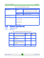
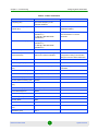
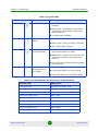
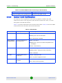
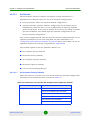
Document History
Document History
Changed Item
Description
Version/
Date Issued
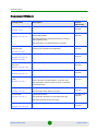
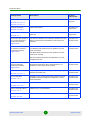
25dBi antenna
Added optional 25dBi antennas for AU-E/SU-E
SW Version 4.0,
July 2006
Improved mechanism for automatic detection of
frequency/bandwidth
SW Version 4.0,
July 2006
Section 1.8.6
Frequency configuration
Section 4.2.6.2.3.2,
Removed parameters: Sub Band select (SU), Frequency
Subset Definition (SU)
New parameters: User Defined Frequency Subsets
Transmit Power, Maximum
Transmit Power
Simplified configuration mechanism: A single parameter
instead of per-modulation level parameters
SW Version 4.0,
July 2006
New feature
SW Version 4.0,
July 2006
Default value updated
SW Version 4.0,
July 2006
Added option: Ethernet Status Control
SW Version 4.0,
July 2006
New feature
SW Version 4.0,
July 2006
Section 4.2.6.2.7
Per SU Distance Learning
Section 4.2.6.2.9.4,
Section 4.2.5.8.2
ATPC Delta from Minimum
SNR Level
Section 4.2.6.2.7.3.3
Tx Control
Section 4.2.6.2.7.5
Service Provider Link (VLAN
QinQ)
Section 4.2.6.4.1
Service Provider Link option added to VLAN Link Type
New parameters: Service Provider VLAN ID, VLAN QinQ
Protocol Ethertype
MAC Address List
Improved functionality
Section 4.2.6.4.7
New parameter: MAC Address List Action
Concatenation
Improved mechanism
Section 4.2.6.5.11
New parameter: Maximum Concatenated Frame Size
SW Version 4.0,
July 2006
SW Version 4.0,
July 2006
Removed: Maximum Number of Frames
IP Precedence Threshold
Default value updated
SW Version 4.0,
July 2006
Section 4.2.6.6.3.2.2
BreezeACCESS 4900
ii
System Manual
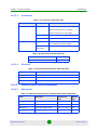
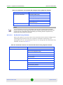
Document History
Changed Item
Description
Version/
Date Issued
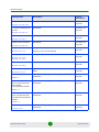
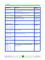
DSCP Threshold
Default value updated
SW Version 4.0,
July 2006
New feature
SW Version 4.0,
July 2006
New feature
SW Version 4.0,
July 2006
New feature
SW Version 4.0,
July 2006
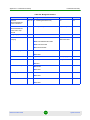
FTP Client IP Address
Changed functionality
Section 4.2.3.12
(read only, set to unit's IP Address)
SW Version 4.0,
July 2006
FTP Server IP Address
Changed default to 10.0.0.253
SW Version 4.0,
July 2006
Maximum value was changed from 15 to 14
SW Version 4.0,
July 2006
Updated maximum length for unit with HW revision C and
higher
SW Version 4.0,
July 2006
Updated according to applicable changes (new/removed
parameters)
SW Version 4.0,
July 2006
Updated according to applicable changes (new/removed
parameters)
SW Version 4.0,
July 2006
Updated according to applicable changes (new/removed
parameters)
SW Version 4.0,
July 2006
Updated according to applicable changes (new/removed
parameters)
SW Version 4.0,
July 2006
Section 4.2.6.6.3.2.3
Low Priority Traffic Minimum
Percent
Section 4.2.6.6.3.5
DRAP support
Section 4.2.6.6.4
Wireless Link Prioritization
Section 4.2.6.6.3.6
Section 4.2.3.12,
Section 4.2.3.9.4
Number of HW Retries
Section 4.2.6.5.8
Ethernet packet length
Section 4.2.5.1.1
Basic Parameters Table
Table 3-1
Parameters that are not
reset to default value after
Set Complete
Factory/Operator Defaults
Table 4-3
Parameters that are not
reset to default value after
Set Partial Factory/Operator
Defaults
Table 4-4
Basic Configuration Menu
Section 4.2.4
BreezeACCESS 4900
iii
System Manual
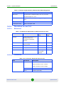
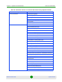
Document History
Changed Item
Description
Version/
Date Issued
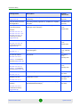
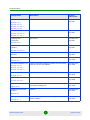
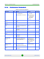
Parameters Summary
(Appendix E)
Updated according to applicable changes (new/removed
parameters)
SW Version 4.0,
July 2006
Using the Feature License
Web Application
Removed (previously Appendix G) - Available as a separate
document.
SW Version 4.0,
July 2006
Q in Q (Service Provider
Link) improvements
Improved handling of management frames. Support of
Ethertypes 9100, 9200 (hex)
SW Version
4.0.27,
October 2006
Default changed to 8171
SW Version
4.0.27,
October 2006
New feature - a procedure for password recovery if password
was lost/forgotten
SW Version
4.0.27, February
2007
New feature
SW Version
4.0.27,
February 2007
New feature
SW Version
4.0.27,
February 2007
Added Country Code, Serial Number and ATE Test Status
SW Version 4.5,
June 2007
Added Other counter
SW Version 4.5,
June 2007
New functionality. Name changed from Broadcast Relaying to
Broadcast/Multicast Relaying
SW Version 4.5,
June 2007
Sections
Section 4.2.6.4.1.2,
Section 4.2.6.4.1.3.4,
Section 4.2.6.4.1.8,
Parameters Summary
(Appendix E)
DRAP UDP Port
Section 4.2.6.6.4.2,
Parameters Summary
(Appendix E)
Password Recovery
Section 4.1.1
AP Client IP Address
Section 4.2.6.3.8
Table 4-4, Parameters
Summary (Appendix E)
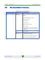
Noise Immunity Control
Section 4.2.6.2.16,
Table 4-4, Parameters
Summary (Appendix E)
Show Unit Status
Section 4.2.2.1
Wireless Tx Events
Section 4.2.5.1.2
Broadcast/Multicast
Relaying
Section 4.2.6.4.5,
Parameters Summary
(Appendix E)
BreezeACCESS 4900
iv
System Manual
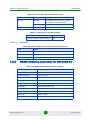
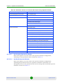
Document History
Changed Item
Description
Version/
Date Issued
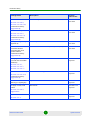
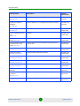
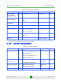
MIR Threshold Percent
New MIR/CIR parameter
SW Version 4.5,
June 2007
New feature
SW Version 4.5,
June 2007
MIB Appendix (previously
Appendix E)
Removed (all information is available in the MIB text file
SW Version 4.5,
June 2007
Minimum and Maximum
Contention Window
parameters Run-Time
Update definition,
Parameters Summary
(Appendix E)
Parameters are not Run-Time Updated (reset required)
SW Version 4.5,
June 2007
SU "aging" mechanism
(removal from Association
Database)
Updated
SW Version 4.5,
July 2007
Default has been changed to Low.
SW Version 4.5,
July 2007
FCC Radiation Hazard
Warning (in Legal Rights)
Updated
SW Version 4.5,
July 2007
Re-apply Country Code
Values
New feature
SW Version 4.5,
July 2007
Added AP Client IP Address
SW Version 4.5,
July 2007
Section 4.2.6.6.5,
Section 4.2.6.6.2.10,
Parameters Summary
(Appendix E)
Station Allowed Option
Section 4.2.6.4.7,
Section 4.2.6.4.7.4,
Parameters Summary
(Appendix E)
Section 4.2.2.1,
Section 4.2.5.4.1,
Section 4.2.6.2.11
Pulse Detection Sensitivity
Section 4.2.6.2.16.5,
Parameters Summary
(Appendix E)
Section 4.2.6.8.2,
Appendix A
Basic Parameters
Section 4.2.4
BreezeACCESS 4900
v
System Manual
Document History
Changed Item
Description
Version/
Date Issued
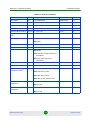
Sub-Band Select in SU
Added/updated descriptions
SW Version 4.5,
July 2007
Improved description
SW Version 4.5,
August 2007
Updated compliance to ETSI standard (EN 302 326-3 V1.2.1
(2007-01)
SW Version 4.5,
August 2007
FTP Server IP Address, FTP Gateway IP Address, FTP User
Name, FTP Password are updated in run-time (reset not
required)
SW Version 5.0,
November 2007
Preferred AU MAC Address, Arbitration Inter-Frame Spacing
and Wireless Trap Threshold are not updated in run-time
(reset is required).
SW Version 5.0,
November 2007
Section 4.2.6.2.4.1,
Section 4.2.6.2.13
MIR/CIR Parameters
Section 4.2.6.6.2
Antenna specifications
Section 1.2.1
Correct Run-Time update of
Unit Control Parameters Parameters Summary
Appendix E
Correct Run-Time update of
Air Interface Parameters Parameters Summary
Appendix E
Sub-Band Select and Frequency are updated in run-time
(reset is not required).
Spectrum Analysis parameters are applicable in run-time
(configured per test)
Correct Run-Time update of
Service Parameters Parameters Summary
MIR: Downlink, MIR: Uplink, CIR: Downlink, CIR: Uplink,
Maximum Burst Duration, MIR Threshold Percent, are
updated in run-time (reset is not required).
SW Version 5.0,
November 2007
Traps are generated and sent only by AU (including traps on
behalf of associated SUs)
SW Version 5.0,
November 2007
Re-apply Country Codes Values option has been removed
(available in Basic and Advanced Configuration, Country
Code Parameters.
SW Version 5.0,
November 2007
Updated name (was previously AP Client IP Address)
SW Version 5.0,
November 2007
Added Country Code Parameters
SW Version 5.0,
November 2007
New
SW Version 5.0,
November 2007
Appendix E
Send Traps
Section 4.2.6.3.7.1
Unit Control Menu
Section 4.2.3
Wi2 IP Address
Section 4.2.6.3.8
Basic Configuration Menu
Section 4.2.4
Country Code Parameters
Section 4.2.6.8
BreezeACCESS 4900
vi
System Manual
Document History
Changed Item
Description
Version/
Date Issued
SU "aging" mechanism
(removal from Association
Database)
Updated
SW Version 5.0,
November 2007
Maximum Number of Associations must be set to 124 or
lower to enable Data Encryption
SW Version 5.0,
November 2007
Updated description of Burst Duration algorithm
SW Version 5.0,
November 2007
The maximum is 4092 bytes. This is also the default for RTS
Threshold in AU.
SW Version 5.0,
November 2007
Updated the information displayed in the various options
SW Version 5.0,
November 2007
Updated the displayed information
SW Version 5.0,
November 2007
Updated details of Menu header
SW Version 5.0,
November 2007
New read-only indications:
SW Version 5.0,
November 2007
Section 4.2.2.1,
Section 4.2.5.4.1,
Section 4.2.6.2.11
Maximum Number of
Associations with Data
Encryption enabled
Section 4.2.6.2.11,
Section 4.2.6.7.2
MIR and CIR Parameters
Section 4.2.6.6.2
RTS Threshold
Section 4.2.6.5.1
MAC Address Database in
AU
Section 4.2.5.4.1
MAC Address Database in
SU
Section 4.2.5.4.2
Menu header
Section 4.1.1
Show Unit Status
Section 4.2.2.1
SU-54 Support (AUS)
Wireless Link Prioritization Support (AU)
Management Solutions
BreezeCONFIG has been replaced by AlvariCRAFT
SW Version 5.0,
November 2007
Added note on potential copy/paste problems
SW Version 5.0,
November 2007
Range has been increased from 1-2 to 1-50 time slots.
SW Version 5.0,
November 2007
Section 1.7.1
Feature License
Section 4.2.3.10
AIFS
Section 4.2.6.2.10
BreezeACCESS 4900
vii
System Manual
Document History
Changed Item
Description
Version/
Date Issued
Data Encryption Option
AU with Data Encryption Option enabled can accept
non-encrypted data frames (previously it was stated that this
is applicable only for SU)
SW Version 5.0,
December 2007
The range has been changed from 3-254 to 3-50.
SW Version 5.0,
December 2007
Country Code Learning By
SU
Removed from the Manual (not applicable for
BreezeACCESS 4900).
SW Version 5.0,
December 2007
Pulse Detection Sensitivity
Description has been updated.
SW Version 5.0,
December 2007
In Display Association Info, RSSI info has been added (per
SU)
SW Version 5.2,
May 2008
New feature
SW Version 5.2,
May 2008
Average RSSI has been added to the display. Added formula
used for calculations.
SW Version 5.2,
May 2008
Added new parameters (OFDM SNR, OFDM Max SNR,
Noise Floor Avg, Noise Floor Max)
SW Version 5.2,
May 2008
Updated manual
SW Version 5.2,
May 2008
RSSI of the received signal has been added
SW Version 5.2,
May 2008
AU-D models (supplied with a detached antenna) are no
longer available. Only AU-E models are available (antennas
are sold separately)
SW Version 5.2,
May 2008
Section 4.2.6.7.2
Low Priority AIFS
Section 4.2.6.6.3.6.2
Section 4.2.6.2.16.5
MAC Address Database in
AU
Section 4.2.5.4.1
Continuous Noise Floor
Display
Section 4.2.5.3.2 (SU),
Section 4.2.5.5 (AU)
Continuous Average
SNR/RSSI Display in SU
Section 4.2.5.3.1
Spectrum Analysis
Information Display
Section 4.2.6.2.13.6
Show Spectrum analysis
Parameters & Data
Section 4.2.6.2.13.8
Show Best AU Parameters
and Data
Section 4.2.6.2.5.4
AU types
Section
Section
Section
Section
Section
Section
1.2,
1.8.1,
1.8.5.2,
1.8.5.3,
2.1.1.2.2,
2.1.1.3
BreezeACCESS 4900
viii
System Manual
Document History
Changed Item
Description
Version/
Date Issued
Hidden ESSID
New feature
SW Version 5.2,
May 2008
New feature
SW Version 5.2,
May 2008
New section
SW Version 5.2,
May 2008
New feature
SW Version 5.2,
May 2008
Updated to reflect all SW version 5.2 changes
SW Version 5.2,
May 2008
Updated
SW Version 5.2,
June 2008
Updated: Association SNAP from another AU is not used for
removal of SU from the database.
SW Version 5.2,
June 2008
Updated (added AUTHENTICATING status)
SW Version 5.2,
June 2008
Corrected (supplier's OUI is 00-10-E7)
SW Version 5.2,
June 2008
Updated: A known parameter with a value that is invalid or
out of range will be ignored
SW Version 5.2,
June 2008
Updated
SW Version 5.2,
June 2008
Updated (clarified that RF cable is not supplied with
AU/SU-E-ODUs)
SW Version 5.2,
June 2008
Section
Section
Section
Section
1.8.1,
4.2.2.1,
4.2.6.2.1,
4.2.5.6
Noise Floor Calculation
Section 4.2.6.2.17,
Section 4.2.3.2.1
Protecting ODU
Connections
Section 2.3.2
Calibration of Noise Floor
Indication
Section 4.2.6.2.18
Appendix E - Parameters
Summary
RESET Button Functionality
Section 2.4.1
Association Database in AU
Section 4.2.2.1,
Section 4.2.5.4.1,
Section 4.2.6.2.11
SU Unit Status
Section 4.2.2.1
MAC Address List
Section 4.2.6.4.7
File Loading
Appendix B
Ethernet Port Connection
Problems
Section F.1
Packing Lists
Section 2.1.1
BreezeACCESS 4900
ix
System Manual
Document History
Changed Item
Description
Version/
Date Issued
Antenna Alignment
Updated and improved
SW Version 5.2,
July 2008
Minimum distance of 10 cm between the ODU and antenna.
SW Version 5.2,
July 2008
New
SW Version 6.0,
October 2009
Updated
SW Version 6.0,
October 2009
Traffic Prioritization
Section 4.2.6.6.3
WLP available free of charge
SW Version 6.0,
October 2009
VLAN Extended Access and
Extended Trunk modes
Section 4.2.6.4.1
Added Extended Access and Extended Trunk link types for
VLAN on SUs
SW Version 6.0,
October 2009
LED Mode
LEDs behavior can be customized
SW Version 6.0,
October 2009
Updated Adaptive Modulation algorithm
SW Version 6.0,
October 2009
Added Proportional IR Factor algorithm
SW Version 6.0,
October 2009
Added IP range prioritization for the priority queue
SW Version 6.0,
October 2009
Added control for ACK frames modulation
SW Version 6.0,
October 2009
Antenna Compliance
Statement
Updated
SW Version 6.6,
August 2011
Modular Base Station
Equipment
AUS-BS now supports 25 SUs instead of 8
SW Version 6.6,
August 2011
AUS-SA now supports 25 SUs instead of 8
SW Version 6.6,
August 2011
Section 3.2
Equipment Positioning
Guidelines
Section 2.2
DC Power Injector
Section 1.4
FIPS 197 certification now
free
Table 1-5
Section 4.2.3.13
Adaptive Modulation
Section 4.2.6.5.10
Proportional IR Factor
Section 4.2.6.6.2.7
IP Range Prioritization
Section 4.2.6.6.3.4
Control Modulation Level
Section 4.2.6.5.6
Section 1.2.1
Standalone Access Units
Section 1.2.2
BreezeACCESS 4900
x
System Manual
Legal Rights
Legal Rights
© Copyright 2011 Alvarion Ltd. All rights reserved.
The material contained herein is proprietary, privileged, and confidential and
owned by Alvarion or its third party licensors. No disclosure thereof shall be made
to third parties without the express written permission of Alvarion Ltd.
Alvarion Ltd. reserves the right to alter the equipment specifications and
descriptions in this publication without prior notice. No part of this publication
shall be deemed to be part of any contract or warranty unless specifically
incorporated by reference into such contract or warranty.
Trade Names
Alvarion®, BreezeCOM®, WALKair®, WALKnet®, BreezeNET®, BreezeACCESS®,
BreezeLINK®, BreezeMAX®, BreezeLITE®, BreezePHONE®, 4Motion® and/or other
products and/or services referenced here in are either registered trademarks,
trademarks or service marks of Alvarion Ltd.
All other names are or may be the trademarks of their respective owners.
Statement of Conditions
The information contained in this manual is subject to change without notice.
Alvarion Ltd. shall not be liable for errors contained herein or for incidental or
consequential damages in connection with the furnishing, performance, or use of
this manual or equipment supplied with it.
Warranties and Disclaimers
All Alvarion Ltd. ("Alvarion") products purchased from Alvarion or through any of
Alvarion's authorized resellers are subject to the following warranty and product
liability terms and conditions.
Exclusive Warranty
(a) Alvarion warrants that the Product hardware it supplies and the tangible
media on which any software is installed, under normal use and conditions, will
be free from significant defects in materials and workmanship for a period of
fourteen (14) months from the date of shipment of a given Product to Purchaser
(the "Warranty Period"). Alvarion will, at its sole option and as Purchaser's sole
remedy, repair or replace any defective Product in accordance with Alvarion'
standard R&R procedure.
(b) With respect to the Firmware, Alvarion warrants the correct functionality
according to the attached documentation, for a period of fourteen (14) month from
invoice date (the "Warranty Period"). During the Warranty Period, Alvarion may
release to its Customers firmware updates, which include additional performance
BreezeACCESS 4900
xi
System Manual
Legal Rights
improvements and/or bug fixes, upon availability (the "Warranty"). Bug fixes,
temporary patches and/or workarounds may be supplied as Firmware updates.
Additional hardware, if required, to install or use Firmware updates must be
purchased by the Customer. Alvarion will be obligated to support solely the two (2)
most recent Software major releases.
ALVARION SHALL NOT BE LIABLE UNDER THIS WARRANTY IF ITS TESTING
AND EXAMINATION DISCLOSE THAT THE ALLEGED DEFECT IN THE PRODUCT
DOES NOT EXIST OR WAS CAUSED BY PURCHASER'S OR ANY THIRD
PERSON'S MISUSE, NEGLIGENCE, IMPROPER INSTALLATION OR IMPROPER
TESTING, UNAUTHORIZED ATTEMPTS TO REPAIR, OR ANY OTHER CAUSE
BEYOND THE RANGE OF THE INTENDED USE, OR BY ACCIDENT, FIRE,
LIGHTNING OR OTHER HAZARD.
Disclaimer
(a) The Product is sold on an "AS IS" basis. Alvarion, its affiliates or its licensors
MAKE NO WARRANTIES, WHATSOEVER, WHETHER EXPRESS OR IMPLIED,
WITH RESPECT TO THE SOFTWARE AND THE ACCOMPANYING
DOCUMENTATION. ALVARION SPECIFICALLY DISCLAIMS ALL IMPLIED
WARRANTIES OF MERCHANTABILITY AND FITNESS FOR A PARTICULAR
PURPOSE AND NON-INFRINGEMENT WITH RESPECT TO THE SOFTWARE.
UNITS OF PRODUCT (INCLUDING ALL THE SOFTWARE) DELIVERED TO
PURCHASER HEREUNDER ARE NOT FAULT-TOLERANT AND ARE NOT
DESIGNED, MANUFACTURED OR INTENDED FOR USE OR RESALE IN
APPLICATIONS WHERE THE FAILURE, MALFUNCTION OR INACCURACY OF
PRODUCTS CARRIES A RISK OF DEATH OR BODILY INJURY OR SEVERE
PHYSICAL OR ENVIRONMENTAL DAMAGE ("HIGH RISK ACTIVITIES"). HIGH
RISK ACTIVITIES MAY INCLUDE, BUT ARE NOT LIMITED TO, USE AS PART OF
ON-LINE CONTROL SYSTEMS IN HAZARDOUS ENVIRONMENTS REQUIRING
FAIL-SAFE PERFORMANCE, SUCH AS IN THE OPERATION OF NUCLEAR
FACILITIES, AIRCRAFT NAVIGATION OR COMMUNICATION SYSTEMS, AIR
TRAFFIC CONTROL, LIFE SUPPORT MACHINES, WEAPONS SYSTEMS OR
OTHER APPLICATIONS REPRESENTING A SIMILAR DEGREE OF POTENTIAL
HAZARD. ALVARION SPECIFICALLY DISCLAIMS ANY EXPRESS OR IMPLIED
WARRANTY OF FITNESS FOR HIGH RISK ACTIVITIES.
(b) PURCHASER'S SOLE REMEDY FOR BREACH OF THE EXPRESS
WARRANTIES ABOVE SHALL BE REPLACEMENT OR REFUND OF THE
PURCHASE PRICE AS SPECIFIED ABOVE, AT ALVARION'S OPTION. TO THE
FULLEST EXTENT ALLOWED BY LAW, THE WARRANTIES AND REMEDIES SET
FORTH IN THIS AGREEMENT ARE EXCLUSIVE AND IN LIEU OF ALL OTHER
WARRANTIES OR CONDITIONS, EXPRESS OR IMPLIED, EITHER IN FACT OR BY
OPERATION OF LAW, STATUTORY OR OTHERWISE, INCLUDING BUT NOT
BreezeACCESS 4900
xii
System Manual
Legal Rights
LIMITED TO WARRANTIES, TERMS OR CONDITIONS OF MERCHANTABILITY,
FITNESS FOR A PARTICULAR PURPOSE, SATISFACTORY QUALITY,
CORRESPONDENCE WITH DESCRIPTION, NON-INFRINGEMENT, AND
ACCURACY OF INFORMATION GENERATED. ALL OF WHICH ARE EXPRESSLY
DISCLAIMED. ALVARION' WARRANTIES HEREIN RUN ONLY TO PURCHASER,
AND ARE NOT EXTENDED TO ANY THIRD PARTIES. ALVARION NEITHER
ASSUMES NOR AUTHORIZES ANY OTHER PERSON TO ASSUME FOR IT ANY
OTHER LIABILITY IN CONNECTION WITH THE SALE, INSTALLATION,
MAINTENANCE OR USE OF ITS PRODUCTS.
Limitation of Liability
(a) ALVARION SHALL NOT BE LIABLE TO THE PURCHASER OR TO ANY THIRD
PARTY, FOR ANY LOSS OF PROFITS, LOSS OF USE, INTERRUPTION OF
BUSINESS OR FOR ANY INDIRECT, SPECIAL, INCIDENTAL, PUNITIVE OR
CONSEQUENTIAL DAMAGES OF ANY KIND, WHETHER ARISING UNDER
BREACH OF CONTRACT, TORT (INCLUDING NEGLIGENCE), STRICT LIABILITY
OR OTHERWISE AND WHETHER BASED ON THIS AGREEMENT OR
OTHERWISE, EVEN IF ADVISED OF THE POSSIBILITY OF SUCH DAMAGES.
(b) TO THE EXTENT PERMITTED BY APPLICABLE LAW, IN NO EVENT SHALL
THE LIABILITY FOR DAMAGES HEREUNDER OF ALVARION OR ITS EMPLOYEES
OR AGENTS EXCEED THE PURCHASE PRICE PAID FOR THE PRODUCT BY
PURCHASER, NOR SHALL THE AGGREGATE LIABILITY FOR DAMAGES TO ALL
PARTIES REGARDING ANY PRODUCT EXCEED THE PURCHASE PRICE PAID
FOR THAT PRODUCT BY THAT PARTY (EXCEPT IN THE CASE OF A BREACH OF
A PARTY'S CONFIDENTIALITY OBLIGATIONS).
Electronic Emission Notices
This device complies with Part 15 of the FCC rules.
Operation is subject to the following two conditions:
1
This device may not cause harmful interference.
2
This device must accept any interference received, including interference that
may cause undesired operation.
FCC Radio Frequency Interference Statement
The Subscriber Unit equipment has been tested and found to comply with the
limits for a class B digital device, pursuant to part 15 of the FCC rules and to ETSI
EN 301 489-1 rules. These limits are designed to provide reasonable protection
against harmful interference when the equipment is operated in a residential
environment notwithstanding use in commercial, business and industrial
environments. This equipment generates, uses, and can radiate radio frequency
BreezeACCESS 4900
xiii
System Manual
Legal Rights
energy and, if not installed and used in accordance with the instruction manual,
may cause harmful interference to radio communications.
The Base Station equipment has been tested and found to comply with the limits
for a class A digital device, pursuant to part 15 of the FCC rules and to EN 301
489-1 rules. These limits are designed to provide reasonable protection against
harmful interference when the equipment is operated in commercial, business
and industrial environments. This equipment generates, uses, and can radiate
radio frequency energy and, if not installed and used in accordance with the
instruction manual, may cause harmful interference to radio communications.
Operation of this equipment in a residential area is likely to cause harmful
interference in which case the user will be required to correct the interference at
the user's own expense.
FCC Radiation Hazard Warning
To comply with FCC RF exposure requirement, the antenna used for this
transmitter must be fixed-mounted on outdoor permanent structures with a
separation distance of at least 2 meter from al persons for antennas with a gain
up to 28 dBi.
Antenna Compliance Statement
This device has been tested and certified to operate with the limited list of
antennas detailed in Table 1-3. It is hereby expressly clarified that installation
and usage of any other antennas shall be under the sole responsibility and
liability of the client. It is the responsibility of the client to assure that such
installation and usage is in full compliance with the applicable local laws and
regulations, including without limitation with respect to the maximum permitted
radiated power. The required antenna impedance is 50 ohms.
To reduce potential radio interference to other users, the antenna type and its
gain should be so chosen that the Equivalent Isotropically Radiated Power (EIRP)
is not more than that permitted for successful communication.
R&TTE Compliance Statement
This equipment complies with the appropriate essential requirements of Article 3
of the R&TTE Directive 1999/5/EC.
Safety Considerations
For the following safety considerations, "Instrument" means the BreezeACCESS
4900 units' components and their cables.
Caution
To avoid electrical shock, do not perform any servicing unless you are qualified to
do so.
BreezeACCESS 4900
xiv
System Manual
Legal Rights
Line Voltage
Before connecting this instrument to the power line, make sure that the voltage of
the power source matches the requirements of the instrument.
Radio
The instrument transmits radio energy during normal operation. To avoid possible
harmful exposure to this energy, do not stand or work for extended periods of time
in front of its antenna. The long-term characteristics or the possible physiological
effects of Radio Frequency Electromagnetic fields have not been yet fully
investigated.
Outdoor Unit and Antenna Installation and Grounding
Ensure that outdoor units, antennas and supporting structures are properly
installed to eliminate any physical hazard to either people or property. Make sure
that the installation of the outdoor unit, antenna and cables is performed in
accordance with all relevant national and local building and safety codes. Even
where grounding is not mandatory according to applicable regulation and national
codes, it is highly recommended to ensure that the outdoor unit and the antenna
mast (when using external antenna) are grounded and suitable lightning
protection devices are used so as to provide protection against voltage surges and
static charges. In any event, Alvarion is not liable for any injury, damage or
regulation violations associated with or caused by installation, grounding or
lightning protection.
Disposal of Electronic and Electrical Waste
Disposal of Electronic and Electrical Waste
Pursuant to the WEEE EU Directive electronic and electrical waste must not be disposed of with
unsorted waste. Please contact your local recycling authority for disposal of this product.
BreezeACCESS 4900
xv
System Manual
Important Notice
Important Notice
This user manual is delivered subject to the following conditions and restrictions:
This manual contains proprietary information belonging to Alvarion Ltd. Such
information is supplied solely for the purpose of assisting properly authorized
users of the respective Alvarion products.
No part of its contents may be used for any other purpose, disclosed to any
person or firm or reproduced by any means, electronic and mechanical,
without the express prior written permission of Alvarion Ltd.
The text and graphics are for the purpose of illustration and reference only.
The specifications on which they are based are subject to change without
notice.
The software described in this document is furnished under a license. The
software may be used or copied only in accordance with the terms of that
license.
Information in this document is subject to change without notice.
Corporate and individual names and data used in examples herein are
fictitious unless otherwise noted.
Alvarion Ltd. reserves the right to alter the equipment specifications and
descriptions in this publication without prior notice. No part of this
publication shall be deemed to be part of any contract or warranty unless
specifically incorporated by reference into such contract or warranty.
The information contained herein is merely descriptive in nature, and does not
constitute an offer for the sale of the product described herein.
Any changes or modifications of equipment, including opening of the
equipment not expressly approved by Alvarion Ltd. will void equipment
warranty and any repair thereafter shall be charged for. It could also void the
user's authority to operate the equipment.
Some of the equipment provided by Alvarion and specified in this manual, is
manufactured and warranted by third parties. All such equipment must be
installed and handled in full compliance with the instructions provided by such
manufacturers as attached to this manual or provided thereafter by Alvarion or
BreezeACCESS 4900
xvi
System Manual
Important Notice
the manufacturers. Non compliance with such instructions may result in serious
damage and/or bodily harm and/or void the user's authority to operate the
equipment and/or revoke the warranty provided by such manufacturer.
BreezeACCESS 4900
xvii
System Manual
About this Manual
About this Manual
This manual describes the BreezeACCESS 4900 Broadband Wireless Access
System and how to install, operate and manage the system components.
This manual is intended for technicians responsible for installing, setting up and
operating the BreezeACCESS 4900 system, and for system administrators
responsible for managing the system.
This manual contains the following chapters and appendices:
Chapter 1 - System description: Describes the BreezeACCESS 4900 system
and its components.
Chapter 2 - Installation: Describes how to install the system components.
Chapter 3 - Commissioning: Describes how to configure basic parameters,
align the Subscriber Unit antenna and validate unit operation.
Chapter 4 - Operation and Administration: Describes how to use the
BreezeACCESS 4900 Monitor application for configuring parameters, checking
system status and monitoring performance.
Appendix A - Software Version Loading Using TFTP: Describes how to load a
new software version using TFTP.
Appendix B - File Download and Upload Using TFTP: Describes how to
download and upload configuration files using TFTP. This procedure is also
applicable for uploading country code and feature license files.
Appendix C - Using the Set Factory Defaults Utility: Describes how to use the
Set Factory Defaults utility to enable management access to units where
wrong or unknown configuration disables regular access to the unit for
management purposes.
Appendix D - Preparing the indoor to outdoor SU cable: Provides details on
preparation of the indoor to outdoor Ethernet cable.
Appendix E - Parameters Summary: Provides an at a glance summary of the
configuration parameters, value ranges and default values.
BreezeACCESS 4900
xviii
System Manual
About this Manual
Appendix F - Troubleshooting.
BreezeACCESS 4900
xix
System Manual
Contents
Contents
Chapter 1 - System Description .............................................................. 1
1.1 Introducing BreezeACCESS 4900.............................................................................3
1.2 Base Station Equipment ............................................................................................5
1.2.1 Modular Base Station Equipment........................................................................5
1.2.2 Standalone "Micro-cell" Access Unit ...................................................................7
1.3 Subscriber Unit...........................................................................................................8
1.4 DC Power Injector ......................................................................................................9
1.5 BreezeACCESS VL B&B (4.9 GHz only) .................................................................11
1.6 Networking Equipment ............................................................................................12
1.7 Management Systems..............................................................................................13
1.7.1 AlvariCRAFT .....................................................................................................13
1.7.2 AlvariSTAR........................................................................................................13
1.8 Specifications ...........................................................................................................15
1.8.1 Radio.................................................................................................................15
1.8.2 Data Communication.........................................................................................16
1.8.3 Configuration and Management........................................................................16
1.8.4 Standards Compliance, General .......................................................................17
1.8.5 Physical and Electrical ......................................................................................18
1.8.6 25dBi Antenna (optional for AU-E/SU-E) ..........................................................22
1.8.7 Environmental ...................................................................................................23
Chapter 2 - Installation.......................................................................... 24
2.1 Installation Requirements .......................................................................................26
2.1.1 Packing List.......................................................................................................26
2.1.2 Indoor-to-Outdoor Cables .................................................................................29
2.2 Equipment Positioning Guidelines.........................................................................31
2.3 Installing the Outdoor Unit ......................................................................................33
2.3.1 Pole Mounting the Outdoor Unit........................................................................33
BreezeACCESS 4900
xx
System Manual
Contents
2.3.2 Protecting ODU Connections ............................................................................36
2.3.3 Connecting the Grounding and Antenna Cables...............................................36
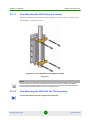
2.3.4 Connecting the Indoor-to-Outdoor Cable ..........................................................37
2.4 Installing the Universal IDU Indoor Unit.................................................................40
2.4.1 RESET Button Functionality..............................................................................41
2.5 Installing the Modular Base Station Equipment....................................................42
2.5.1 BS-SH Slot Assignment ....................................................................................42
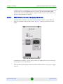
2.5.2 BS-PS-AC Power Supply Module .....................................................................43
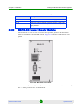
2.5.3 BS-PS-DC Power Supply Module .....................................................................44
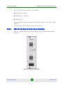
2.5.4 BS-AU Network Interface Module .....................................................................45
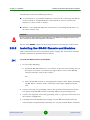
2.5.5 Installing the BS-SH Chassis and Modules.......................................................46
Chapter 3 - Commissioning ................................................................... 48
3.1 Configuring Basic Parameters................................................................................50
3.1.1 Initial Configuration ...........................................................................................50
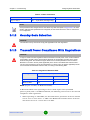
3.1.2 Country Code Selection ....................................................................................52
3.1.3 Transmit Power Compliance With Regulations .................................................52
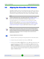
3.2 Aligning the Subscriber Unit Antenna ...................................................................54
3.3 Configuring the Subscriber Unit's Maximum Modulation Level ..........................56
3.4 Operation Verification..............................................................................................58
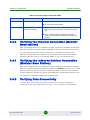
3.4.1 Outdoor Unit Verification ...................................................................................58
3.4.2 Indoor Unit Verification......................................................................................60
3.4.3 Verifying the Ethernet Connection (Modular Base station) ...............................61
3.4.4 Verifying the Indoor-to-Outdoor Connection (Modular Base Station)................61
3.4.5 Verifying Data Connectivity ...............................................................................61
Chapter 4 - Operation and Administration ............................................ 62
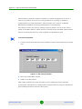
4.1 Working with the Monitor Program ........................................................................64
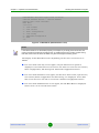
4.1.1 Accessing the Monitor Program Using Telnet...................................................64
4.1.2 Common Operations .........................................................................................66
4.2 Menus and Parameters ............................................................................................67
4.2.1 Main Menu ........................................................................................................67
4.2.2 Info Screens Menu ............................................................................................67
4.2.3 Unit Control Menu .............................................................................................73
4.2.4 Basic Configuration Menu .................................................................................89
BreezeACCESS 4900
xxi
System Manual
Contents
4.2.5 Site Survey Menu..............................................................................................92
4.2.6 Advanced Configuration Menu........................................................................108
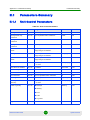
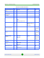
E.1 Parameters Summary ............................................................................................212
E.1.1 Unit Control Parameters..................................................................................212
E.1.2 IP Parameters .................................................................................................214
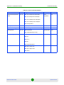
E.1.3 Air Interface Parameters .................................................................................214
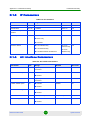
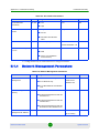
E.1.4 Network Management Parameters .................................................................217
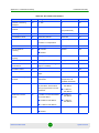
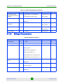
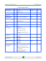
E.1.5 Bridge Parameters ..........................................................................................218
E.1.6 Performance Parameters ................................................................................221
E.1.7 Service Parameters.........................................................................................222
E.1.8 Security Parameters........................................................................................225
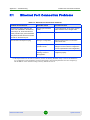
F.1 Ethernet Port Connection Problems ....................................................................228
F.2 SU Association Problems......................................................................................229
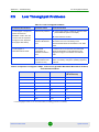
F.3 Low Throughput Problems....................................................................................230
BreezeACCESS 4900
xxii
System Manual
Figures
Figures
Figure 1-1: Modular Base Station Equipment ............................................................................... 5
Figure 1-2: AU E-BS Access Unit.................................................................................................. 6
Figure 1-3: Standalone AU-E-SA Access Unit .............................................................................. 7
Figure 1-4: DC Power Injector....................................................................................................... 9
Figure 1-5: DC Power Injector Cable ............................................................................................9
Figure 2-1: Threaded Holes/Grooves.......................................................................................... 34
Figure 2-2: 3" Pole Installation Using Special Clamps ................................................................ 35
Figure 2-3: .................................................................................................................................. 35
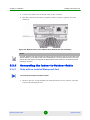
Figure 2-4: Bottom Panel of the Outdoor Unit (without the seal assembly) ................................ 37
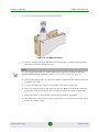
Figure 2-5: The Waterproof Seal................................................................................................. 38
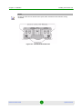
Figure 2-6: IDU PS 1073 Front Panel ......................................................................................... 40
Figure 2-7: BS-SH Chassis Slot Assignment .............................................................................. 42
Figure 2-8: BS-PS-AC Front Panel ............................................................................................. 43
Figure 2-9: BS-PS-DC Front Panel ............................................................................................. 44
Figure 2-10: BS-AU Front Panel ................................................................................................. 45
Figure 4-1: Main Menu (Administrator Level) .............................................................................. 65
Figure 4-2: Service Provider Link .............................................................................................. 147
Figure C-1: Set Factory Defaults............................................................................................... 206
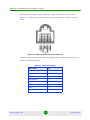
Figure D-1: Ethernet Connector Pin Assignments .................................................................... 208
BreezeACCESS 4900
xxiii
System Manual
Tables
Tables
Table 1-1: AU Detached Antennas ............................................................................................... 6
Table 1-2: Subscriber Unit ODU Types......................................................................................... 8
Table 1-3: Radio Specifications................................................................................................... 15
Table 1-4: Data Communication.................................................................................................. 16
Table 1-5: Configuration and Management................................................................................. 16
Table 1-6: Standards Compliance, General ................................................................................ 17
Table 1-7: Mechanical Specifications, Subscriber Unit ............................................................... 18
Table 1-8: Connectors, Subscriber Unit ...................................................................................... 19
Table 1-9: Ethernet Pin-Out Assignments................................................................................... 19
Table 1-10: Electrical Specifications, Subscriber Unit................................................................. 19
Table 1-11: Mechanical Specifications, Modular Base Station Equipment ................................. 19
Table 1-12: Connectors, Modular Base Station Equipment ........................................................ 20
Table 1-13: Ethernet Pin-Out Assignments................................................................................. 20
Table 1-14: Electrical Specifications, Modular Base Station Equipment..................................... 20
Table 1-15: Mechanical Specifications, Stand Alone Access Unit .............................................. 21
Table 1-16: Connectors, Stand Alone Access Unit ..................................................................... 21
Table 1-17: Ethernet Pin-Out Assignments................................................................................. 22
Table 1-18: Electrical Specifications, Stand Alone Access Unit.................................................. 22
Table 1-19: 25dBi Antenna Specifications (optional) .................................................................. 22
Table 1-20: Environmental Specifications ................................................................................... 23
Table 2-1: Subscriber Unit ODU Types....................................................................................... 26
Table 2-2: Access Unit ODU Types ............................................................................................ 27
Table 2-3: Access Unit ODU Types ............................................................................................ 28
BreezeACCESS 4900
xxiv
System Manual
Tables
Table 2-4: Approved Category 5E Ethernet Cables .................................................................... 30
Table 2-5: BS-PS LED Functionality ........................................................................................... 44
Table 3-1: Basic Parameters....................................................................................................... 50
Table 3-2: Regulation Maximum EIRP ........................................................................................ 52
Table 3-3: Recommended Maximum Modulation Level .............................................................. 57
Table 3-4: AU-ODU LEDs ........................................................................................................... 58
Table 3-5: SU-ODU LEDs ........................................................................................................... 59
Table 3-6: SU-ODU SNR Bar LED Functionality (In Normal Mode)............................................ 59
Table 3-7: BS-AU LEDs .............................................................................................................. 60
Table 3-8: PS1073 SU IDU / AU-SA IDU LEDs .......................................................................... 61
Table 4-1: Default Passwords ..................................................................................................... 64
Table 4-2: Sub-Band Dependent Parameters ............................................................................. 72
Table 4-3: Parameters not reset after Set Complete Factory/Operator Defaults ........................ 75
Table 4-4: Parameters that are not reset after Set Partial Factory/Operator Defaults ................ 76
Table 4-5: Threshold Target Value Ranges ................................................................................ 89
Table 4-6: Authentication and Association Process .................................................................. 103
Table 4-7: VLAN Management Port Functionality ..................................................................... 144
Table 4-8: VLAN Data Port Functionality - Access Link ............................................................ 145
Table 4-9: VLAN Data Port Functionality - Trunk Link .............................................................. 146
Table 4-10: VLAN Data Port Functionality - Hybrid Link ........................................................... 147
Table 4-11: VLAN Data Port Functionality for SU - Service Provider Link ................................ 148
Table 4-12: VLAN Data Port Functionality for AU - Service Provider Link ................................ 148
Table 4-13: Extended Trunk Frame Routing ............................................................................. 150
Table 4-14: VLAN Rule # Parameters....................................................................................... 154
Table 4-15: Layer 2 Broadcast/Multicast Frames’ Behavior...................................................... 156
Table 4-16: Recommended Maximum Modulation Level .......................................................... 167
BreezeACCESS 4900
xxv
System Manual
Tables
Table 4-17: Basic Rate Mechanism .......................................................................................... 167
Table 4-18: Retransmission Percentage Equivalence .............................................................. 171
Table 4-19: Examples of Retransmissions on Different Modulation Levels .............................. 172
Table 4-20: MIR Ranges and Defaults ...................................................................................... 179
Table 4-21: CIR Ranges and Defaults ...................................................................................... 179
Table 4-22: Used Uplink MIR for Various PIF Values (Configured Uplink MIR = 54 Mbps)...... 181
Table D-1: Cable Color Codes .................................................................................................. 208
Table E-1: Unit Control Parameters .......................................................................................... 212
Table E-2: IP Parameters.......................................................................................................... 214
Table E-3: Air Interface Parameters.......................................................................................... 214
Table E-4: Network Management Parameters .......................................................................... 217
Table E-5: Bridge Parameters................................................................................................... 218
Table E-6: Performance Parameters......................................................................................... 221
Table E-7: Service Parameters ................................................................................................. 222
Table E-8: Security Parameters ................................................................................................ 225
Table F-1: Ethernet Port Connection Problems ........................................................................ 228
Table F-2: SU Association Problems ........................................................................................ 229
Table F-3: Low Throughput Problems....................................................................................... 230
Table F-4: Expected Throughput in Mbps, TCP session @ 10 MHz Bandwidth Burst
Mode Enabled, Concatenation Enabled.................................................................................... 230
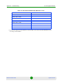
Table F-5: Recommended Maximum Modulation Level* .......................................................... 231
BreezeACCESS 4900
xxvi
System Manual
Chapter
1
System Description
Chapter 1 - System Description
In This Chapter:
“Introducing BreezeACCESS 4900” on page 3
“Base Station Equipment” on page 5
“Subscriber Unit” on page 8
“Networking Equipment” on page 12
“Management Systems” on page 13
“Specifications” on page 15
BreezeACCESS 4900
2
System Manual
Chapter 1 - System Description
1.1
Introducing BreezeACCESS 4900
Introducing BreezeACCESS 4900
BreezeACCESS 4900 is a high capacity, IP services oriented Broadband Wireless
Access system operating in the 4.9 GHz licensed spectrum band allocated for
public safety. The system employs wireless packet switched data technology to
support high-speed IP services including fast Internet and Virtual Private
Networks.BreezeACCESS 4900 users are provided with a network connection that
is always on, supporting immediate access to the Internet and other IP services at
high data rates. The system is designed for both Point-to-Point and Point-to
Multipoint configurations, supporting data, VoIP and video applications.
The system supports Virtual LANs based on IEEE 802.1Q, enabling secure
operation and Virtual Private Network (VPN) services and enabling tele-workers or
remote offices to conveniently access their enterprise network. The system
supports layer-2 traffic prioritization based on IEEE 802.1p and layer-3 traffic
prioritization based on either IP ToS Precedence (RFC791) or DSCP (RFC2474). It
also supports traffic prioritization based on UDP and/or TCP port ranges. In
addition, it may use the optional Wireless Link Prioritization (WLP) feature to fully
support delay sensitive applications, enabling Multimedia Application
Prioritization (MAP) for high performance voice and video. The implementation of
MAP through the unique WLP protocol revolutionizes the business model by
increasing, for example, the number of simultaneous VoIP calls per sector by as
much as 500%.
BreezeACCESS 4900 uses advanced security mechanisms, including WEP128,
AES128 and FIPS 197 compliant encryption algorithms.
Using OFDM modem technology and high power radios, BreezeACCESS 4900
offers an unmatched combination of wide coverage, high capacity and
value-added features to provide wireless connectivity that works also in near and
non line of site (NLOS) conditions.
The Complete Spectrum solution enables the BreezeACCESS 4900 to integrate
seamlessly into other BreezeACCESS networks. Supporting both fixed and mobile
platforms at multiple frequency bands, the Complete Spectrum enables
simultaneous deployment of systems at 900 MHz, 2.4 GHz, 3.5 GHz, 4.9 GHz, and
the entire 5 GHz band.
BreezeACCESS 4900 products operate in unlicensed frequency bands in Time
Division Duplex (TDD) mode, using Orthogonal Frequency Division Multiplexing
(OFDM) modulation with Forward Error Correction (FEC) coding. Using the
enhanced multi-path resistance capabilities of OFDM modem technology,
BreezeACCESS 4900 enables operation in near and non line of sight (NLOS)
BreezeACCESS 4900
3
System Manual
Chapter 1 - System Description
Introducing BreezeACCESS 4900
environments. These qualities enable service providers to reach a previously
inaccessible and broader segment of the subscriber population.
A BreezeACCESS 4900 system comprises the following:
Customer Premise Equipment (CPE): BreezeACCESS 4900 Subscriber Units
(SUs).
Base Station Equipment (BS): BreezeACCESS 4900 Access Units and
supporting equipment.
Networking Equipment: Standard Switches/Routers supporting connections
to the backbone and/or Internet.
Management Systems: SNMP-based Management, Billing and Customer Care,
and other Operation Support Systems.
BreezeACCESS 4900
4
System Manual
Chapter 1 - System Description
1.2
Base Station Equipment
Base Station Equipment
The Access Units, installed at the Base Station site, provide all the functionality
necessary to communicate with the Subscriber Units and to connect to the
backbone of the Service Providers.
There are 2 lines of Access Units with different architectures:
Modular Base Station Equipment
Standalone "Micro-Cell" Access Unit
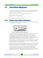
1.2.1
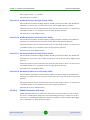
Modular Base Station Equipment
The Base Station Equipment is based on the BS-SH 3U chassis, which is suitable
for installation in 19-inch racks.
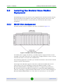
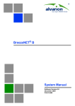
Figure 1-1: Modular Base Station Equipment
The chassis contains one or two Power Supply modules and has 8 slots that can
accommodate BS-AU Network Interface modules. These slots can also
accommodate various combinations of other modules, including Network
Interface (BS AU) modules for Access Units operating in any of the bands
supported by BreezeACCESS VL equipment or BreezeACCESS equipment using
GFSK modulation, including BreezeACCESS 900, BreezeACCESS II,
BreezeACCESS XL and BreezeACCESS V. It can also accommodate a BS GU GPS
and Alarms module to support GPS-based synchronization of BreezeACCESS
systems using Frequency Hopping radios.
Two different types of power supply modules are available for the BreezeACCESS
4900 chassis: The BS-PS-DC that is powered from a 48 VDC power source, and
the BS-PS-AC, powered from the 110/220 VAC mains. The optional use of two
power supply modules ensures fail-safe operation through power supply
redundancy. When the same chassis is used also for Access Unit modules
belonging to other BreezeACCESS families using GFSK modulation, then one BS
PS power supply (AC or DC) should be used to provide power to the
BreezeACCESS 4900
5
System Manual
Chapter 1 - System Description
Base Station Equipment
BreezeACCESS 4900 Access Units, and a different power supply module, suitable
for GFSK equipment, is required for powering the BreezeACCESS GFSK Access
Units.
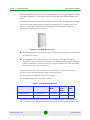
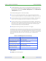
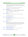
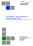
Each BS-AU module and its outdoor radio unit (AU-ODU) comprise an AU E-BS
Access Unit that together with an external antenna serve a single sector/cell.
There are two types of Access Units, differing in the maximum number of
Subscriber Units that they can serve:
Figure 1-2: AU E-BS Access Unit
The AU-BS Access Unit can serve up to 512 Subscriber Units (124 when Data
Encryption is used).
The AUS-BS Access Unit can serve up to 25 SUs except SU-54 (refer to
“Subscriber Unit” on page 8 for details on availability of SU types in different
bands). Optionally, it may be licensed to support also SU-54 units (in bands
where SU-54 unit type is available.).
The AU-ODU outdoor unit contains the processing and radio modules and
connects to an external antenna using a short RF cable.
E model units are supplied without an antenna.
The available antennas are listed in Table 1-1.
Table 1-1: AU Detached Antennas
Unit
Antenna
Band
(GHz)
Horizontal
Beam
Width
Gain
(dBi)
AU-D-BS-4900-120
AU-Ant-4.9G-15-120
4.900-5.100
120
15
AU-D-BS-4900-360
AU-Ant-4.9G-9-Omni
4.900-5.100
360
9
The BS-AU indoor module connects to the network through a standard IEEE
802.3 Ethernet 10/100BaseT (RJ 45) interface. The indoor module is connected to
BreezeACCESS 4900
6
System Manual
Chapter 1 - System Description
Base Station Equipment
the outdoor unit via a Category 5E Ethernet cable. This cable carries Ethernet
traffic between the indoor module and the outdoor unit, and also transfers power
(54 VDC) and control from the indoor module to the outdoor unit.
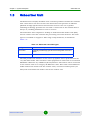
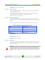
1.2.2
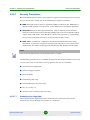
Standalone "Micro-cell" Access Unit
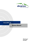
Figure 1-3: Standalone AU-E-SA Access Unit
The standalone AU-E-SA Access Unit is very similar to the AU-E-BS unit. The
difference is in the structure of the indoor part; in the AU E-SA Access Unit the
indoor unit is a standalone desktop or wall mountable unit (the same Universal
IDU that is also used in the SU) rather than a 19" module.
There are two types of Standalone Access Units, differing in the maximum
number of Subscriber Units that they can serve:
The AU-SA Access Unit can serve up to 512 Subscriber Units (124 when Data
Encryption is used).
The AUS-SA Access Unit can serve up to 25 SUs except SU-54 (refer to section
1.3 for details on availability of SU types in different bands). Optionally, it may
be licensed to support also SU-54 units (in bands where SU-54 unit type is
available.).
NOTE
For convenience, all references to AU-SA are applicable also for AUS-SA, unless explicitly stated
otherwise.
The IDU connects to the network through a standard IEEE 802.3 Ethernet
10/100BaseT (RJ 45) interfaces and is powered from the 110/240 VAC mains.
The indoor unit is connected to the outdoor unit via a Category 5 Ethernet cable.
This cable carries Ethernet traffic between the indoor and the outdoor units, and
also transfers power (54 VDC) and control from the indoor unit to the outdoor
unit.
BreezeACCESS 4900
7
System Manual
Chapter 1 - System Description
1.3
Subscriber Unit
Subscriber Unit
The Subscriber Unit (SU) installed at the customer premises enables the customer
data connection to the Access Unit. The Subscriber Unit provides an efficient
platform for high speed Internet and Intranet services. The use of packet
switching technology provides the user with a connection to the network that is
always on, enabling immediate access to services.
The Subscriber Unit comprises a desktop or wall-mountable Indoor Unit (IDU)
and an outdoor unit that contains the processing and radio modules. Two ODU
types are available to support a wide range of requirements, as detailed in
Table 1-2:
Table 1-2: Subscriber Unit ODU Types
SU Type
Antenna Description
SU-A-ODU
Vertically polarized high-gain flat antenna integrated on the front
panel
SU-E-ODU
A connection to an external antenna
The IDU provides the interface to the user's equipment and is powered from the
110/220 VAC mains. The customer's data equipment is connected via a standard
IEEE 802.3 Ethernet 10/100BaseT (RJ 45) interface. The indoor unit is connected
to the outdoor unit via a Category 5E Ethernet cable. This cable carries Ethernet
traffic between the indoor and the outdoor units, and also transfers power (54
VDC) and control from the indoor unit to the outdoor unit.
BreezeACCESS 4900
8
System Manual
Chapter 1 - System Description
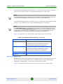
1.4
DC Power Injector
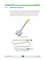
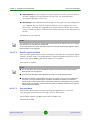
DC Power Injector
The DC Power Injector is an indoor unit designed for sites in which protected DC
sources are available (48 to 55 VDC), such as many of the GSM sites. This allows
operators to utilize their existing protected backup DC systems to feed the VL
outdoor units. For this purpose, the unit comes with a 3 m DC cable, with an
RJ45 plug at one end that goes into the injector and 3 wires (+, -, GND) at the
other end that will need to go into a plug suitable for the DC power source.
Figure 1-4: DC Power Injector
Figure 1-5: DC Power Injector Cable
BreezeACCESS 4900
9
System Manual
Chapter 1 - System Description
DC Power Injector
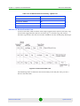
The DC Power Injector has two RJ45 jacks at one end (see Figure 1-4):
WAN/Eth: For connection to the network
DC IN: For connection to the DC power source via the supplied cable (see
Figure 1-5)
The other end has another RJ45 jack for connecting to the outdoor unit via an
Ethernet cable
CAUTION
When using the injector, the following restrictions apply:
The DC Power Injector does not include surge protection for either the DC or Ethernet input.
External protection devices are required for surge protection.
The nominal output voltage is between 50 to 58 VDC with a DC load of 0 to 1 A. If the nominal
output is below 50 VDC, the cable linking the IDU and ODU must be shorter than 100 m.
The external power supply must support overcurrent/short circuit protection with auto recovery
function. In case of overcurrent, the power supply must turn off and on (hiccup mechanism).
BreezeACCESS 4900
10
System Manual
Chapter 1 - System Description
1.5
BreezeACCESS VL B&B (4.9 GHz only)
BreezeACCESS VL B&B (4.9 GHz only)
BreezeACCESS VL B&B is available to support point-to-point applications. A B&B
point-to-point link includes:
AU-D-SA-4.9-6-VL: A standalone AU with a 25 dBi, 6° high gain directional
antenna.
SU-D-4.9-54-BD-VL: SU-54-BD with a 25 dBi, 6° high gain directional
antenna.
BreezeACCESS 4900
11
System Manual
Chapter 1 - System Description
1.6
Networking Equipment
Networking Equipment
The Base Station equipment is connected to the backbone through standard data
communication and telecommunication equipment. The 10/100BaseT ports of
the AU modules can be connected directly to a multi-port router or to an Ethernet
switch connected to a router.
The point-to-point link from the Base Station to the backbone can be either wired
or wireless. Data to the Internet is routed to the backbone through standard
routers.
BreezeACCESS 4900
12
System Manual
Chapter 1 - System Description
1.7
Management Systems
Management Systems
The end-to-end IP-based architecture of the system enables full management of
all components, from any point in the system. BreezeACCESS 4900 components
can be managed using standard management tools through SNMP agents that
implement standard and proprietary MIBs for remote setting of operational modes
and parameters. The same SNMP management tools can also be used to manage
other system components including switches, routers and transmission
equipment. Security features incorporated in BreezeACCESS 4900 units restrict
access for management purposes to specific IP addresses and/or directions, that
is, from the Ethernet and/or wireless link.
In addition, the Ethernet WAN can be used to connect to other Operation Support
Systems including servers, Customer Care systems and AAA (Authentication,
Authorization and Admission) tools.
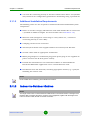
1.7.1
AlvariCRAFT
AlvariCRAFT is an SNMP (Simple Network Management Protocol) application
designed for on-line management of system components. This utility simplifies the
installation and maintenance of small size installations by easily enabling the
change of settings or firmware upgrade for one unit or an entire sector at a time.
AlvariCRAFT allows accessing a wide array of monitoring and configuration
options, including:
Device Manager for the selected Unit
Selected unit or a complete sector configuration modification
Firmware upgrade for a single unit or an entire sector
On-line performance data monitoring
Export of configuration details to a CSV file
Support for Telnet cut-through to the managed devices and http cut-through to
Gateways or Wi2 APs behind connected SUs.
1.7.2
AlvariSTAR
AlvariSTAR is a comprehensive Carrier-Class network management system for
Alvarion's Broadband Wireless Access products-based Networks. AlvariSTAR is
BreezeACCESS 4900
13
System Manual
Chapter 1 - System Description
Management Systems
designed for today's most advanced Service Provider Network Operation Centers
(NOCs), providing the network Operation, Administration and Maintenance
(OA&M) staff and managers with all the network surveillance, monitoring and
configuration capabilities that they require in order to effectively manage the BWA
network while keeping the resources and expenses at a minimum.
AlvariSTAR is designed to offer the network's OA&M staff with a unified, scalable
and distributable network management system. The AlvariSTAR system uses a
distributed client-server architecture, which provides the service provider with a
robust, scalable and fully redundant network management system in which all
single points of failure can be avoided.
AlvariSTAR provides the following BWA network management functionality:
Device Discovery
Device Inventory
Topology
Fault Management
Configuration Management
Data Collection
Performance Monitoring
Device embedded Software Upgrade
Security Management
Northbound interface to other Network Management Systems.
Embedded with the entire knowledge base of BWA network operations,
AlvariSTAR is a unique state-of-the-art power multiplier in the hands of the
service provider that enables the provisioning of satisfied customers. AlvariSTAR
dramatically extends the abilities of the service provider to provide a rich portfolio
of services and to support rapid customer base expansion.
BreezeACCESS 4900
14
System Manual
Chapter 1 - System Description
Specifications
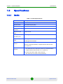
1.8
Specifications
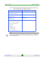
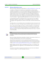
1.8.1
Radio
Table 1-3: Radio Specifications
Item
Description
Frequency
4.940 - 4.990 GHz
Operation Mode
Time Division Duplex (TDD)
Channel Bandwidth
10 MHz / 5 MHz
Central Frequency
Resolution
5 MHz
Antenna Port (AU
ODU)
N-Type, 50 ohm
Max. Input Power
-40 dBm typical
(at antenna port)
Maximum Output
Power
20 dBm @ 10 MHz Bandwidth
SU-A-ODU Integral
Antenna
20 dBi, 10.5o horizontal x 10.5o vertical,
AU Detached
Antennas
AU-Ant-4.9G-15-120: 15 dBi, 4.900-5.100 GHz,
17 dBm @ 5 MHz Bandwidth
vertical or horizontal polarization, compliant with ETSI EN 302 326-3
V1.2.1 (2007-01)
124o horizontal x 6.5o vertical sector antenna, vertical polarization,
compliant with ETSI EN 302 326-3 V1.2.1 (2007-01)
AU-Ant-4.9G-9-Omni: 9 dBi, 4.900-5.100 GHz,
360o horizontal x 8o vertical, vertical polarization
BreezeACCESS 4900
15
System Manual
Chapter 1 - System Description
Specifications
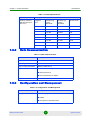
Table 1-3: Radio Specifications
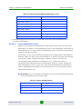
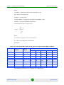
1.8.2
Item
Description
Sensitivity, Minimum
(dBm at antenna port,
PER<10%)
Modulation
Level1
Sensitivity @
5 MHz
Bandwidth
Sensitivity @
10 MHz
Bandwidth
Minimum SNR
1
-95 dBm
-92 dBm
6 dB
2
-94 dBm
-91 dBm
7 dB
3
-93 dBm
-90 dBm
9 dB
4
-91 dBm
-88 dBm
11 dB
5
-88 dBm
-85 dBm
14 dB
6
-84 dBm
-81 dBm
18 dB
7
-80 dBm
-77 dBm
22 dB
8
-78 dBm
-75 dBm
23 dB
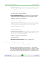
Data Communication
Table 1-4: Data Communication
Item
Description
Standard compliance
IEEE 802.3 CSMA/CD
VLAN Support
Based on IEEE 802.1Q
Layer 2 Traffic Prioritization
Based on IEEE 802.1p
Layer 3 Traffic Prioritization
IP Precedence ToS (RFC791)
DSCP (RFC2474)
Source/destination IP address
Layer 4 Traffic Prioritization
1.8.3
UDP/TCP destination ports
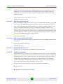
Configuration and Management
Table 1-5: Configuration and Management
Item
Description
Management
Monitor program via Telnet
SNMP
Configuration upload/download
BreezeACCESS 4900
16
System Manual
Chapter 1 - System Description
Specifications
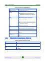
Table 1-5: Configuration and Management
Item
Description
Management Access
From Wired LAN, Wireless Link
Management access
protection
Multilevel password
Configuration of remote access direction (from
Ethernet only, from wireless link only or from both)
Configuration of IP addresses of authorized stations
Security
Authentication messages encryption option
Data encryption option
WEP and AES OCB 128-bit encryption algorithms
FIPS 197 certified encryption (for Access Units with
HW revision C or higher)
ESSID and Hidden ESSID
SNMP Agents
SNMP ver. 1 client
MIB II, Bridge MIB, Private BreezeACCESS MIB
Allocation of IP parameters
Configurable or automatic (DHCP client)
Software upgrade
FTP
TFTP
Configuration
upload/download
FTP
TFTP
1.8.4
Standards Compliance, General
Table 1-6: Standards Compliance, General
Type
Standard
EMC
FCC Part 15 class B
ETSI EN 301 489-1
Safety
UL60950-1
EN 60950-1
BreezeACCESS 4900
17
System Manual
Chapter 1 - System Description
Specifications
Table 1-6: Standards Compliance, General
Type
Standard
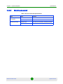
Environmental
Operation
ETS 300 019 part 2-3 class 3.2E for indoor
ETS 300 019 part 2-4 class 4.1E for outdoor
Storage
ETS 300 019-2-1 class 1.2E
Transportation
ETS 300 019-2-2 class 2.3
Lightning protection (AU-ODU
Antenna connection)
EN 61000-4-5, Class 3 (2kV)
Radio
ETSI EN 301 893
ETSI EN 302502
FCC Part 15.247
FCC part15.407
FCC part 90
1.8.5
Physical and Electrical
1.8.5.1
Subscriber Unit
1.8.5.1.1
Mechanical
Table 1-7: Mechanical Specifications, Subscriber Unit
Unit
Structure
Dimensions
(cm)
Weight
(kg)
General
An IDU indoor unit and an SU A
ODU outdoor unit with an integral
antenna
IDU PS1073
Plastic box (black), desktop or
wall mountable
14 x 6.6 x 3.5
0.3
SU A ODU
Metal box plus an integral
antenna in a cut diamond shape
in a plastic enclosure, poll or wall
mountable
41.5 x 36.9 x 6.3
2.3
SU-E-ODU
Metal box, pole or wall mountable
30.5 x 11.7 x 5.7
1.8
BreezeACCESS 4900
18
System Manual
Chapter 1 - System Description
1.8.5.1.2
Specifications
Connectors
Table 1-8: Connectors, Subscriber Unit
Unit
Connector
Description
IDU
ETHERNET
10/100BaseT Ethernet (RJ-45)
Cable connection to a PC: crossed
Cable connection to a hub: straight
SU A/E ODU
RADIO
10/100BaseT Ethernet (RJ-45)
AC IN
3 pin AC power plug
INDOOR
10/100BaseT Ethernet (RJ-45), protected
by a waterproof sealing assembly
ANT
(SU-E-ODU)
N-Type jack, 50 ohm, lightning protected
Table 1-9: Ethernet Pin-Out Assignments
1.8.5.1.3
Radio
Power
Pins: 4 & 7 Power (+) 5 & 8 Power (-)
56V
Electrical
Table 1-10: Electrical Specifications, Subscriber Unit
Unit
Details
General
Power consumption: 25W
IDU
AC power input: 85-265 VAC, 50-60 Hz
SU A ODU
54 VDC from the IDU over the indoor-outdoor Ethernet cable
1.8.5.2
Modular Base Station Equipment
1.8.5.2.1
Mechanical
Table 1-11: Mechanical Specifications, Modular Base Station Equipment
Unit
Structure
Dimensions
(cm)
Weight
(kg)
BS-SH
19" rack (3U) or desktop
13 x 48.2 x 25.6
4.76
BS-PS-DC
DC power supply module
12.9 x 7.0 x 25.3
1.2
BS-PS-AC
AC power supply module
12.9 x 7.0 x 25.3
1.2
BS-AU
Indoor module of the AU-D-BS
12.9 x 3.5 x 25.5
0.15
BreezeACCESS 4900
19
System Manual
Chapter 1 - System Description
Specifications
Table 1-11: Mechanical Specifications, Modular Base Station Equipment
1.8.5.2.2
Unit
Structure
Dimensions
(cm)
Weight
(kg)
AU-ODU
pole or wall mountable
30.5 x 11.7 x 5.7
1.8
AU-Ant-4.9G-15-120
2"-4" pole mountable
55 x 25 x 1.7
1.5
Connectors
Table 1-12: Connectors, Modular Base Station Equipment
Unit
Connector
Description
BS-AU
10/100 BaseT
10/100BaseT Ethernet (RJ-45) with 2
embedded LEDs.
Cable connection to a PC: crossed
Cable connection to a hub: straight
RADIO
10/100BaseT Ethernet (RJ-45) with 2
embedded LEDs
INDOOR
10/100BaseT Ethernet (RJ-45), protected by a
waterproof sealing assembly
ANT
N-Type jack, 50 ohm, lightning protected
BS-PS-AC
AC-IN
3-PIN AC power plug
BS-PS-DC
-48 VDC
3 pin DC D-Type 3 power pins plug
AU-ODU
Amphenol 717TWA3W3PHP2V4RRM6
Antenna
RF
N-Type jack (on a 1.5m cable in the
Omni-8-5.8)
Table 1-13: Ethernet Pin-Out Assignments
1.8.5.2.3
Radio
Power
Pins: 4 & 7 Power (+) 5 & 8 Power (-)
56V
Electrical
Table 1-14: Electrical Specifications, Modular Base Station Equipment
Unit
Details
General
240W max. for a fully equipped chassis (1 PS, 6 AU)
BS-PS-AC
AC power input: 85-265 VAC, 47-65 Hz
DC power output: 54 V; 3.3 V
BreezeACCESS 4900
20
System Manual
Chapter 1 - System Description
Specifications
Table 1-14: Electrical Specifications, Modular Base Station Equipment
Unit
Details
BS-PS-DC
DC power input: -48 VDC nominal (-34 to -72), 10 A max
DC power output: 54 V; 3.3 V
BS-AU
3.3 VDC, 54 VDC from the power supply module(s) via the back
plane
AU-ODU
54 VDC from the BS-AU over the indoor-outdoor Ethernet cable
AU-BS (IDU+ODU)
Power consumption: 30W
1.8.5.3
Standalone Access Unit
1.8.5.3.1
Mechanical
Table 1-15: Mechanical Specifications, Stand Alone Access Unit
1.8.5.3.2
Unit
Structure
Dimensions
(cm)
Weight
(kg)
General
An IDU indoor unit and an AU D
BS ODU outdoor unit
connected to a detached
antenna
IDU PS1073
Plastic box (black), desktop or
wall mountable
14 x 6.6 x 3.5
0.3
AU-ODU
Poll or wall mountable
30.5 x 11.7 x 5.7
1.8
AU-Ant-4.9G-15-120
2"-4" pole mountable
55 x 25 x 1.7
1.5
AU-Ant-4.9G-9-Omni
1.5"-3" pole mountable
46 cm high,
5.5 cm base
diameter
0.6
Connectors
Table 1-16: Connectors, Stand Alone Access Unit
Unit
Connector
Description
IDU
ETHERNET
10/100BaseT Ethernet (RJ-45)
Cable connection to a PC: crossed
Cable connection to a hub: straight
BreezeACCESS 4900
RADIO
10/100BaseT Ethernet (RJ-45)
AC IN
3-PIN AC power plug
21
System Manual
Chapter 1 - System Description
Specifications
Table 1-16: Connectors, Stand Alone Access Unit
Unit
Connector
Description
AU ODU
INDOOR
10/100BaseT Ethernet (RJ-45), protected
by a waterproof sealing assembly
ANT
N-Type jack, 50 ohm, lightning protected
RF
N-Type jack
Antenna
Table 1-17: Ethernet Pin-Out Assignments
1.8.5.3.3
Radio
Power
Pins: 4 & 7 Power (+) 5 & 8 Power (-)
56V
Electrical
Table 1-18: Electrical Specifications, Stand Alone Access Unit
1.8.6
Unit
Details
General
Power consumption: 25W
IDU
AC power input: 85-265 VAC, 50-60 Hz
AU ODU
54 VDC from the IDU over the indoor-outdoor Ethernet cable
25dBi Antenna (optional for AU-E/SU-E)
Table 1-19: 25dBi Antenna Specifications (optional)
Item
Description
Regulatory Compliance
ETSI EN 302 085 V1.1.2 (2001-02) Range1
Frequency Range
4.900-5.100 GHz
Gain
25dBi min.
Azimuth Beamwidth
6°
Elevation Beamwidth
6°
Polarization
Linear (Vertical/Horizontal)
Dimensions (cm)
45 x 45 x 3
Weight (kg)
3 (max, excluding mounting kit)
Connector
N-Type, Female
Mounting Kit
2.75"-3.5" pole, 0 to -10 tilt, 2.2kg
BreezeACCESS 4900
22
System Manual
Chapter 1 - System Description
1.8.7
Specifications
Environmental
Table 1-20: Environmental Specifications
Type
Unit
Details
Operating
temperature
Outdoor units
-40 o C to 55 o C
Indoor equipment
0 o C to 40 o C
Operating humidity
Outdoor units
5%-95% non condensing, weather protected
Indoor equipment
5%-95% non condensing
BreezeACCESS 4900
23
System Manual
Chapter
2
Installation
Chapter 2 - Installation
In This Chapter:
“Installation Requirements” on page 26
“Equipment Positioning Guidelines” on page 31
“Installing the Outdoor Unit” on page 33
“Installing the Universal IDU Indoor Unit” on page 40
“Installing the Modular Base Station Equipment” on page 42
BreezeACCESS 4900
25
System Manual
Chapter 2 - Installation
2.1
Installation Requirements
Installation Requirements
This section describes all the supplies required to install the BreezeACCESS 4900
system components and the items included in each installation package.
2.1.1
Packing List
2.1.1.1
Subscriber Unit
The SU installation kit includes the following components:
IDU indoor unit with a wall mounting kit
Mains power cord
Any of the following outdoor units:
»
SU-A-ODU outdoor unit with an integrated vertically polarized antenna
OR
»
SU-E-ODU outdoor unit with a connection to an external antenna
Table 2-1: Subscriber Unit ODU Types
SU ODU Type
Description
SU-A-ODU
A rectangular enclosure plus a diamond shaped vertically polarized
high-gain flat antenna integrated on the front panel (41.5 x 36.9 x 6.3 cm).
HW revision D or lower.
New SU-A-ODU
A diamond shaped enclosure (22 x 22 x 7 cm) with a vertically/horizontally
polarized high-gain flat antenna integrated on the front panel.
The smaller size new SU-A-ODU (HW revision E) is currently available only
in the 5.4 GHz and 5.8 GHz bands.
SU-E-ODU
A rectangular enclosure (30.5 x 11.7 x 5.7 cm) with a connection to an
external antenna (antenna and cable not included). HW revision D or lower.
New SU-E-ODU
A diamond shaped enclosure (22 x 22 x 7 cm) with a connection to an
external antenna (antenna and cable not included).
BreezeACCESS 4900
26
System Manual
Chapter 2 - Installation
Installation Requirements
NOTE
The SU-A-ODU and SU-E-ODU are supplied without the waterproof sealing assembly for the
INDOOR connector. The sealing assembly is supplied with the IDU to ODU cable kit.
Pole mounting kit for the ODU (the kit for the new, smaller-size ODU is
different from the kit for all other ODUs)
20m Category 5E indoor-to-outdoor Ethernet cable with shielded RJ-45
connectors
2.1.1.2
Modular Base Station Equipment
This section describes the items included in the installation packages for each
Modular Base Station system component.
2.1.1.2.1
BS-SH Base Station Chassis
The BS-SH installation kit includes the following components:
BS-SH chassis with blank panels
Rubber legs for optional desktop installation
2.1.1.2.2
AU-E-BS Access Unit
The AU-E-BS and installation kit includes the following components:
BS-AU Network Interface module
AU-ODU outdoor unit
Pole mounting kit for the AU-ODU (the kit for the new, smaller-size ODU is
different from the kit for all other ODUs)
Table 2-2: Access Unit ODU Types
AU ODU Type
Description
AU-E-ODU
A rectangular enclosure (30.5 x 11.7 x 5.7 cm) with a connection to an
external antenna (antenna and cable not included). HW revision D or
lower.
2.1.1.2.3
BS-PS-AC Power Supply
Up to two BS-PS-AC power supply modules can be included in each Base Station
chassis. The BS-PS-AC installation kit includes the following components:
BreezeACCESS 4900
27
System Manual
Chapter 2 - Installation
Installation Requirements
BS-PS-AC power supply module
Mains power cord
2.1.1.2.4
BS-PS-DC Power Supply
Up to two BS-PS-DC power supply modules can be included in each Base Station
chassis. The BS-PS-DC installation kit includes the following components:
BS-PS-DC power supply module
DC power cable
2.1.1.3
AU-E-SA Standalone Access Unit
The AU-E-SA installation kit includes the following components:
IDU indoor unit with a wall mounting kit
Mains power cord
AU-ODU outdoor unit
Table 2-3: Access Unit ODU Types
AU ODU Type
Description
AU-E-ODU
A rectangular enclosure (30.5 x 11.7 x 5.7 cm) with a connection to an
external antenna (antenna and cable not included). HW revision D or
lower.
Pole mounting kit for the AU-ODU (the kit for the new, smaller-size ODU is
different from the kit for all other ODUs)
2.1.1.4
Optional Items Available from Alvarion
IDU to ODU Category 5 Ethernet cable kit with a shielded RJ-45 connector
crimped on one end and two shielded RJ-45 connectors (available in different
lengths. For more details refer to section “Indoor-to-Outdoor Cables” on
page 29).
Antenna (for SU/AU-E-ODUs) and RF cable.
Tilt Pole Mounting kit for the new, smaller size ODU.
BreezeACCESS 4900
28
System Manual
Chapter 2 - Installation
Installation Requirements
A Y-cable for connecting directly to the IDU COM of ODUs with a new (smaller
size) enclosure for configuration/performance monitoring using a portable PC.
2.1.1.5
Additional Installation Requirements
The following items are also required to install the BreezeACCESS 4900 system
components:
Indoor-to-outdoor Category 5E Ethernet cable with shielded RJ-45 connectors
* (available in different lengths. For more details refer to Section 2.1.2)
Ethernet cable (straight for connecting to a hub/switch etc., crossed for
connecting directly to a PC's NIC)
Crimping tool for RJ-45 connectors
Antenna (for E model units supplied without an antenna) and RF cable.
Ground cables with an appropriate termination
Mains plug adapter or termination plug (if the power plug on the supplied AC
power cord does not fit local power outlets)
Portable PC with Ethernet card and Telnet software or AlvariCRAFT for
BreezeACCESS 4900* application and a crossed Ethernet cable
Installation tools and materials, including appropriate means (e.g. a pole) for
installing the outdoor unit.
NOTE
Items marked with an asterisk (*) are available from Alvarion.
2.1.2
Indoor-to-Outdoor Cables
NOTE
The length of the indoor-to-outdoor Ethernet cable should not exceed 90 meters. The length of the
Ethernet cable connecting the indoor unit to the user's equipment, together with the length of the
Indoor-to-Outdoor cable, should not exceed 100 meters.
BreezeACCESS 4900
29
System Manual
Chapter 2 - Installation
Installation Requirements
Use only Category 5E Ethernet cables from approved manufacturers, listed in
Table 2-4. Consult with Alvarion specialists on the suitability of other cables.
Table 2-4: Approved Category 5E Ethernet Cables
Manufacturer
Part Number
Synergy Cables Ltd.
612098
www.synergy-cables.com
HES Cabling Systems
H5E-00481
www.hescs.com
Teldor
8393204101
www.teldor.com
Southbay Holdings Limited
TSM2404A0D
11th Fl., 15, Lane 347, Jong Jeng Rd.
Shin Juang City, Taipei County
Taiwan, R.O.C
Attn: Eva Lin
Tel. 886-2-2832 3339
Fax. 886-2-2206 0081
E-mail: [email protected]
NOTE
In case of missing information (product specifications, ordering information, etc.) regarding these
products on the manufacturer's web site, it is highly recommended to contact the manufacturer's
sales representative directly.
BreezeACCESS 4900
30
System Manual
Chapter 2 - Installation
2.2
Equipment Positioning Guidelines
Equipment Positioning Guidelines
This section provides key guidelines for selecting the optimal installation locations
for the various BreezeACCESS 4900 system components.
CAUTION
ONLY experienced installation professionals who are familiar with local building and safety codes
and, wherever applicable, are licensed by the appropriate government regulatory authorities should
install outdoor units and antennas.
Failure to do so may void the BreezeACCESS 4900 product warranty and may expose the end user
or Service Provider to legal and financial liabilities. Alvarion and its resellers or distributors are not
liable for injury, damage or regulation violations associated with the installation of Outdoor Units or
antennas.
Select the optimal locations for the equipment using the following guidelines:
The outdoor unit can be either pole or wall mounted. Its location should
enable easy access to the unit for installation and testing.
The higher the placement of the antenna, the better the achievable link
quality.
AU-ODU units without an integral antenna should be installed as close as
possible to the antenna (to ensure that the antenna's characteristics are not
affected by the ODU the distance must be higher than 10 cm).
The antenna connected to the AU-ODU unit, should be installed so as to
provide coverage to all Subscriber Units (SUs) within its service area.
NOTE
The recommended minimum distance between any two antennas serving adjacent sectors is 2
meters. The recommended minimum distance between two antennas serving opposite cells
(installed back-to-back) is 5 meters.
The antenna of the SU (integrated or external) should be installed to provide a
direct, or near line of sight with the Base Station antenna. The antenna should
be aligned to face the Base Station.
In some cases it might be necessary to up/down-tilt the antenna. An optional
Tilt accessory for the ODU providing a tilt range of +/-15° is available from
Alvarion. The tilt option might be necessary to either improve the link
conditions or, if the SU is too close to the Base Station, to reduce the receive
BreezeACCESS 4900
31
System Manual
Chapter 2 - Installation
Equipment Positioning Guidelines
signals strength. As a rule of thumb, if the SU is located at a distance of less
than 300 meters from the Base Station, it is recommended to up-tilt the
antenna by approximately 10° to 15° (especially in line-of-sight conditions) to
avoid saturation of the receivers by too strong signals.
The indoor equipment should be installed as close as possible to the location
where the indoor-to-outdoor cable enters the building. The location of the
indoor equipment should take into account its connection to a power outlet
and the customer's equipment.
BreezeACCESS 4900
32
System Manual
Chapter 2 - Installation
2.3
Installing the Outdoor Unit
Installing the Outdoor Unit
The following sections describe how to install the outdoor units, including pole
mounting the ODU, and connecting the indoor-to-outdoor, grounding and RF
cables
NOTE
Ensure that outdoor units, antennas and supporting structures are properly installed to eliminate
any physical hazard to either people or property. Make sure that the installation of the outdoor unit,
antenna and cables is performed in accordance with all relevant national and local building and
safety codes. Even where grounding is not mandatory according to applicable regulation and
national codes, it is highly recommended to ensure that the outdoor unit and the antenna pole
(when using external antenna) are grounded and suitable lightning protection devices are used so
as to provide protection against voltage surges and static charges. In any event, Alvarion is not
liable for any injury, damage or regulation violations associated with or caused by installation,
grounding or lightning protection.
2.3.1
Pole Mounting the Outdoor Unit
The Outdoor Unit can be mounted on a pole using one of the following options:
Special clamps and threaded rods are supplied with each unit. There are two
pairs of threaded holes on the back of the unit, enabling to use the special
clamps for mounting the unit on diverse pole diameters.
Special grooves on the sides of the unit enable the use of metal bands to
secure the unit to a pole. The bands must be 9/16 inches wide and at least 12
inches long. The metal bands are not included with the installation package.
BreezeACCESS 4900
33
System Manual
Chapter 2 - Installation
Installing the Outdoor Unit
NOTE
Be sure to mount the unit with the bottom panel, which includes the LED indicators, facing
downward.
Figure 2-1: Threaded Holes/Grooves
BreezeACCESS 4900
34
System Manual
Chapter 2 - Installation
2.3.1.1
Installing the Outdoor Unit
Pole Mounting the ODU Using the Clamps
Figure 2-2 illustrates the method of mounting an outdoor unit on a pole, using
the clamps and threaded rods.
Figure 2-2: 3" Pole Installation Using Special Clamps
Figure 2-3:
NOTE
There is a groove on one end of the threaded rod. Be sure to insert the threaded rods with the
grooves pointing outward, and fasten them to the unit using a screwdriver. Install the unit with the
bottom pannel, which includes the connectors, facing downward.
2.3.1.2
Pole Mounting the ODU with the Tilt Accessory
To mount the ODU on a pole using the Tilt accessory:
BreezeACCESS 4900
35
System Manual
Chapter 2 - Installation
1
Installing the Outdoor Unit
Attach the Tilt accessory to the ODU using the two pairs of flat washers, spring
washers and nuts supplied in the Tilt kit.
1
Mount the Tilt accessory on a 1" to 4" pole using two 9/16" metal bands.
1
Release slightly the Tilt Control Screw, tilt the ODU downward/upward as
required, and re-tighten the screw.
2.3.2
Protecting ODU Connections
Use appropriate sealing material to protect the connection against moisture and
humidity. Use removable sealing material, such as a tar seal, to enable future
access to the connector.
NOTE
Use high quality sealing material such as Scotch® 130C Linerless Rubber Splicing Tape from 3M to
ensure protection against dust and water.
Loop and tie the cable near the unit for strain relief and for routing water away
from the unit: use additional cable strips to route the cable such that water can
accumulate on the cable bends, away from the unit.
2.3.3
Connecting the Grounding and Antenna
Cables
The Grounding screw (marked
) is located on the bottom panel of the outdoor
unit. The Antenna RF connector (marked
) is located on the top panel of the
AU-ODU.
To connect the grounding cable:
1
Connect one end of a grounding cable to the grounding terminal and tighten
the grounding screw firmly.
2
Connect the other end of the grounding cable to a good ground (earth)
connection
To connect the RF cable (units with external antenna):
1
Connect one end of the coaxial RF cable to the RF connector on the unit.
BreezeACCESS 4900
36
System Manual
Chapter 2 - Installation
Installing the Outdoor Unit
2
Connect the other end of the RF cable to the antenna.
3
The RF connectors should be properly sealed to protect against rain and
moisture.
Figure 2-4: Bottom Panel of the Outdoor Unit (without the seal assembly)
NOTE
The MAC Address of the unit is marked on both the ODU and the indoor unit (on the print side of the
BS-AU module or on the bottom side of the Universal IDU). If for any reason the ODU is not used
with the IDU with which it was shipped, the MAC Address of the system is in accordance with the
marking on the ODU.
2.3.4
Connecting the Indoor-to-Outdoor Cable
2.3.4.1
Units with an Installed Waterproof Seal
To connect the indoor-to-outdoor cable:
1
Remove the two screws holding the waterproof seal to the outdoor unit and
remove the waterproof seal.
BreezeACCESS 4900
37
System Manual
Chapter 2 - Installation
2
Installing the Outdoor Unit
Unscrew the top nut from the waterproof seal.
Figure 2-5: The Waterproof Seal
3
Route a straight Category 5E Ethernet cable (8-wire, 24 AWG) through both
the top nut and the waterproof seal.
NOTE
Use only Category 5E 4x2x24# FTP outdoor cables from an approved manufacturer. See list of
approved cables and length limitations in “Indoor-to-Outdoor Cables” on page 29.
4
Insert and crimp the RJ-45 connector. Refer to Appendix D for instructions on
preparing the cable.
5
Connect the Ethernet cable to the outdoor unit RJ-45 connector.
6
Place the waterproof seal and then the top nut. Make sure that the external
jack of the cable is well inside the waterproof seal to guarantee a good seal.
7
Route the cable to the location selected for the indoor equipment.
8
Assemble an RJ-45 connector with a protective cover on the indoor end of the
indoor-to-outdoor cable.
BreezeACCESS 4900
38
System Manual
Chapter 2 - Installation
2.3.4.2
Installing the Outdoor Unit
Units with a Waterproof Seal Supplied with the Ethernet
Cable
To connect the indoor-to-outdoor cable:
1
Verify that the o-ring supplied with the cable kit is in place.
2
Connect the RJ-45 connector of the Ethernet cable to the outdoor unit.
3
Attach the waterproof seal to the unit. Tighten the top nut.
4
Route the cable to the location selected for the indoor equipment.
5
Assemble an RJ-45 connector with a protective cover on the indoor end of the
indoor-to-outdoor cable.
See Appendix D for instructions on preparing the cable.
BreezeACCESS 4900
39
System Manual
Chapter 2 - Installation
2.4
Installing the Universal IDU Indoor Unit
Installing the Universal IDU Indoor Unit
The unit can be placed on a desktop or a shelf. Alternatively, it may be
wall-mounted using the kit supplied with the unit.
Figure 2-6: IDU PS 1073 Front Panel
The RADIO connector and RESET button are located on the front panel, the
ETHERNET connector is located on the side panel and LEDs are located on the
top panel.
CAUTION
Do not connect the data equipment to the RADIO port. The RADIO port supplies DC power to the
ODU, and this may harm other equipment connected to it.
To install the IDU:
1
Connect the Indoor-to-Outdoor cable to the RADIO connector, located on the
front panel of the indoor unit.
2
Connect the power cord to the unit's AC socket, located on the rear panel.
Connect the other end of the power cord to the AC mains. The unit can operate
with AC mains of 100-240 VAC, 50-60 Hz.
NOTE
The color codes of the power cable are as follows:
Brown
Blue
YellowGreen
3
Phase
Neutral
Ground
~
0
Verify that the POWER LED is lit, indicating that power is supplied to the unit.
BreezeACCESS 4900
40
System Manual
Chapter 2 - Installation
Installing the Universal IDU Indoor Unit
4
Configure the basic parameters as described in Section 3.1.
5
Connect the 10/100 BaseT ETHERNET connector to the network. The cable
connection should be a straight Ethernet if connecting the indoor unit to a
hub/switch and a crossed cable if connecting it directly to a PC Network
Interface Card (NIC).
NOTE
The length of the Ethernet cable connecting the indoor unit to the user's equipment, together with
the length of the Indoor-to-Outdoor cable, should not exceed 100 meters.
2.4.1
RESET Button Functionality
Using a sharp object, press the recessed RESET button for a short time to reset
the unit and reboot from the Main version.
In units with ODU HW revision C and higher, the RESET button also can also be
used for setting the unit to its factory defaults. Press the button for about 10
seconds (until the ETH LED of the IDU stops blinking): the unit will reboot with
the factory default configuration.
BreezeACCESS 4900
41
System Manual
Chapter 2 - Installation
2.5
Installing the Modular Base Station Equipment
Installing the Modular Base Station
Equipment
The following sections describe the slot assignment for the Base Station chassis,
provide illustrated descriptions of the power supply modules and Access Unit
network interface modules, and describe how to install the Base Station
equipment.
2.5.1
BS-SH Slot Assignment
The Base Station chassis comprises ten slots, as shown in Figure 2-7.
Figure 2-7: BS-SH Chassis Slot Assignment
To enable power supply redundancy, two BS-PS power supply modules can be
installed in the wider side slots. If a single power supply module is used, it can be
inserted into either one of the two available slots.
The remaining eight slots can hold up to six BS-AU modules. Unused slots should
remain covered until required.
The design of the BS-SH supports collocation of BreezeACCESS 4900 Access
Units with Access Units belonging to BreezeACCESS VL family or other
BreezeACCESS families using GFSK modulation. It supports any mixture of
BS-AU 4900 modules with BreezeACCESS VL or BreezeACCESS GFSK BS-AU
modules, including an optional BS GU GPS module. If Access Units belonging to
BreezeACCESS GFSK families are used, then it is necessary to use two power
BreezeACCESS 4900
42
System Manual
Chapter 2 - Installation
Installing the Modular Base Station Equipment
supply modules: one BS-PS (AC or DC) power supply for the BreezeACCESS 4900
Access Units and one BS-PS GFSK (AC or DC) for the BreezeACCESS GFSK
Access Units. The same BS-PS power supply modules can be used to power also
BreezeACCESS VL BS-AU modules.
2.5.2
BS-PS-AC Power Supply Module
The BS-PS-AC is an AC to DC converter that provides power to all the BS-AU
modules installed in the BS-SH chassis. Figure 2-8 shows the BS PS AC front
panel.
Figure 2-8: BS-PS-AC Front Panel
The BS-PS-AC includes a power input connector, marked AC IN, for connecting
the AC power cord to the mains.
The ON/OFF Power Switch controls the flow of mains power to the power supply
module.
BreezeACCESS 4900
43
System Manual
Chapter 2 - Installation
Installing the Modular Base Station Equipment
Table 2-5: BS-PS LED Functionality
2.5.3
Name
Description
54V
Green LED. Indicates that the 54V power supply module is OK
3.3V
Green LED. Indicates that the 3.3V power supply module is OK
OVER TEMP
Red LED. Indicates an over temperature condition in the power
supply module
BS-PS-DC Power Supply Module
The BS-PS-DC is a DC-to-DC converter that provides power to all the BS-AU
modules installed in the BS-SH chassis. Figure 2-9 shows the BS PS DC front
panel.
Figure 2-9: BS-PS-DC Front Panel
The BS PS-DC provides a power input connector, marked -48 VDC, for connecting
the -48 VDC power source to the module.
BreezeACCESS 4900
44
System Manual
Chapter 2 - Installation
Installing the Modular Base Station Equipment
The color codes of the cable wires are as follows:
Black (pin 2): 48 VDC
White (pin 1): + (Return)
Shield (pin 3)
The ON/OFF Power Switch controls the flow of mains power to the power supply
module.
The functionality of the LEDs is described in Table 2-5.
2.5.4
BS-AU Network Interface Module
Figure 2-10 shows the front panel of the BS-AU Access Unit Network Interface
module.
Figure 2-10: BS-AU Front Panel
BreezeACCESS 4900
45
System Manual
Chapter 2 - Installation
Installing the Modular Base Station Equipment
The BS-AU provides the following interfaces:
10/100 BaseT: A 10/100BaseT Ethernet connector for connecting the BS-AU
to the network. A straight Ethernet cable should be used to connect the
module to a hub, router or switch.
RADIO: A 10/100BaseT Ethernet connector for connecting the BS-AU to an
AU-ODU outdoor unit.
CAUTION
Do not connect the data equipment to the RADIO port. The RADIO port supplies DC power to the
ODU, and this may harm other equipment connected to it.
The recessed RESET switch on the front panel is for resetting the outdoor unit.
2.5.5
Installing the BS-SH Chassis and Modules
This section describes how to install the power supply and Access Unit network
interface modules in the Base Station chassis.
To install the BS SH chassis and modules:
1
Do one of the following:
»
Install the BS-SH chassis in a 19" cabinet. To prevent over-heating, leave a
free space of at least 1U between the upper/lower covers of the BS-SH
chassis and other units in the cabinet.
OR
»
Place the BS-SH chassis on an appropriate shelf or table. When mounting
the BS-SH on a shelf or table, attach the rubber legs supplied with the
unit.
2
Connect one end of a grounding cable to the ground terminal located on the
rear panel of the BS-SH chassis and firmly tighten the grounding screw.
3
Connect the opposite end of the grounding cable to a ground connection or to
the cabinet, if applicable.
4
Carefully insert the BS-PS power supply and the BS-AU modules into the
relevant slots and push firmly until they are securely locked. Before insertion,
BreezeACCESS 4900
46
System Manual
Chapter 2 - Installation
Installing the Modular Base Station Equipment
verify that the switches of all BS-PS modules are in the OFF position. Refer to
“BS-SH Slot Assignment” on page 42 for a description of the slot assignment.
5
Close the captive screws attached to each module.
6
Place blank covers over all of the unused slots.
7
Connect the indoor-to outdoor cable(s) to the RADIO connector(s) of the BS-AU
module(s).
8
If a BS-PS-DC power supply is used, connect the DC power cord to the -48
VDC IN jack of the BS-PS-DC power supply. If a redundant power supply
module is installed, connect a DC power cord also to the second DC power
module. Connect the power cord(s) to the -48 VDC power source, as follows:
9
a
Connect the black wire to the 48 VDC contact of the power source.
b
Connect the red wire to the + (Return) contact.
c
Connect the shield to the ground.
If a BS-PS-AC power supply is used, connect the AC power cord to the AC IN
jack of the BS-PS-AC power supply. If a redundant power supply module is
installed, connect an AC power cord also to the second AC power module.
Connect the power cord(s) to the mains outlet.
10 Switch the BS-PS-AC/DC power supplies to ON. Verify that all power indicator
LEDs on the BS-PS-AC/DC front panel are ON and that the OVERTEMP alarm
indicator is off. Refer to Table ?2-2 for a description of these LEDs.
11 Configure the basic parameters in all BS-AU modules as described in
Section 3.1.
12 Connect the 10/100 BaseT LAN connector(s) to the network. The cable
connection should be straight Ethernet if connecting the indoor unit to a
hub/switch and a crossed cable if connecting it directly to a PC Network
Interface Card (NIC).
NOTE
The length of each of the Ethernet cables (the cable connecting the indoor unit to the user's
equipment and the Indoor-to-Outdoor cable) should not exceed 100 meters.
Reset the unit using the RESET button after connecting or reconnecting the indoor and outdoor
units with the indoor-to-outdoor cable.
BreezeACCESS 4900
47
System Manual
Chapter
3
Commissioning
Chapter 3 - Commissioning
In This Chapter:
“Configuring Basic Parameters” on page 50
“Aligning the Subscriber Unit Antenna” on page 54
“Configuring the Subscriber Unit's Maximum Modulation Level” on page 56
“Operation Verification” on page 58
BreezeACCESS 4900
49
System Manual
Chapter 3 - Commissioning
Configuring Basic Parameters
3.1
Configuring Basic Parameters
3.1.1
Initial Configuration
After completing the installation process, as described in the preceding chapter,
the basic parameters must be configured to ensure that the unit operates
correctly. After the basic parameters have been configured, additional parameters
can be remotely configured via the Ethernet port or the wireless link using Telnet
or SNMP management, or by loading a configuration file.
Refer to Section 4.1 for information on how to access the Monitor program using
Telnet and how to use it.
The Basic Configuration menu includes all the parameters necessary for the
initial installation and operation of Subscriber and Access Units. In many
installations, most of these parameters should not be changed from their default
values. The basic parameters and their default values are listed in Table 3-1.
Refer to Chapter 4 for detailed information on the applicable parameters.
Table 3-1: Basic Parameters
Parameter
Default Value
Comment
Ethernet Port Negotiation Mode
(in Unit Control Parameters)
Auto Negotiation
IP Address
10.0.0.1
Subnet Mask
255.0.0.0
Default Gateway Address
0.0.0.0
DHCP Options
Disable
Access to DHCP
AU: From Ethernet Only
SU: From Wireless Only
ESSID
ESSID1
Hidden ESSID Option (AU)
Disable
Hidden ESSID Support (SU)
Disable
Operator ESSID Option (AU)
Enable
Operator ESSID (AU)
ESSID1
Sub-Band Select (AU)
1
BreezeACCESS 4900
Applicable only if Operator ESSID
Option is set to Enable.
50
System Manual
Chapter 3 - Commissioning
Configuring Basic Parameters
Table 3-1: Basic Parameters
Parameter
Default Value
Frequency (AU)
The lowest frequency in the
selected Sub-Band
User Defined Frequency
Subsets (SU)
A (All)
The list of all frequencies in the two
available Sub-Band.
Transmit Power
20 dBM @ 10 MHz Bandwidth
(Sub-Band 1)
17 dBm @ 5 MHz Bandwidth
(Sub-Band 2)
In SU, Transmit Power cannot be higher
than the Maximum Tx Power
parameter.
Maximum Tx Power (SU)
20 dBM @ 10 MHz Bandwidth
(Sub-Band 1)
17 dBm @ 5 MHz Bandwidth
(Sub-Band 2)
Tx Power (AU)
On
Antenna Gain (units with
external antenna)
According to the antenna supplied
with the unit and the Sub-Band.
ATPC Option
Enable
Best AU Support (SU)
Disable
Preferred AU MAC Address
(SU)
00-00-00-00-00-00 (none)
Cell Distance Mode (AU)
Automatic
Maximum Cell Distance (AU)
0 (No Compensation)
Fairness Factor (AU)
100 (%)
Per SU Distance Learning (AU)
Disable
Maximum Modulation Level
(SU)
8
Wi2 IP Address (SU)
0.0.0.0 (none)
VLAN ID-Management
65535
Authentication Algorithm
Open System
Data Encryption Option
Disable
Security Mode
WEP
Default Multicast Key (AU)
Key 1
Promiscuous Authentication
(AU)
Disable
Default Key (SU)
Key 1
BreezeACCESS 4900
Comment
If set to "Not Set Yet", must be
configured according to actual value,
taking into account cable's attenuation.
Applicable only when Best AU Support
is enabled.
Refer to Section 3.3.
51
System Manual
Chapter 3 - Commissioning
Configuring Basic Parameters
Table 3-1: Basic Parameters
Parameter
Default Value
Comment
Key 1 to Key 4
00……0 (32 zeros, meaning no key)
NOTE
Some parameters are changed to their new values only after reset (refer to Appendix E for more
details). After the basic parameters are configured, the unit should be reset in order to activate the
new configuration.
3.1.2
Country Code Selection
CAUTION
The selected Country Code must comply with applicable local radio regulations.
3.1.3
Transmit Power Compliance With Regulations
CAUTION
In regions where local radio regulations limit the maximum transmit power of the unit the installer is
responsible to properly set the Antenna Gain parameter (if configurable) according to the actual
antenna being used. This will limit the upper limits of the Tx Power parameter in the AU and the
Maximum Tx Power in the SU (where applicable) to the value of "Permitted EIRP-Antenna Gain".
The Tx Power parameter in the AU and the Maximum Tx Power in the SU (where applicable) should
not exceed the Permitted EIRP-Antenna Gain, according to the following table:
Table 3-2: Regulation Maximum EIRP
Country Code
Maximum EIRP (dBm)
20 MHz Bandwidth
10 MHz Bandwidth
Japan 4.9 GHz
34
34 (NOTE 1)
Brazil 4.9 GHz
29
26
NOTE (Japan 4.9 GHz, 10 MHz Bandwidth):
In BreezeACCESS units operating in the 4.9 GHz Japan band (not B&B
point-to-point) with a 10 MHz bandwidth, the following rules must be met for full
compliance with regulations:
1
When operating at 4945 MHz, the Transmit Power parameter in the AU should
not be set to a value above 11 dBm. The Maximum Transmit Power of the SU
should not be set to a value above 10 dBm.
BreezeACCESS 4900
52
System Manual
Chapter 3 - Commissioning
2
Configuring Basic Parameters
When operating at 5055 MHz, the Transmit Power parameter in the AU should
not be set to a value above 13 dBm. The Maximum Transmit power of the SU
should not be set to a value above 10 dBm.
BreezeACCESS 4900
53
System Manual
Chapter 3 - Commissioning
3.2
Aligning the Subscriber Unit Antenna
Aligning the Subscriber Unit Antenna
The SNR bar display is located on the bottom panel of the outdoor unit. The ten
LEDs indicate the quality of the received signal. The higher the number of green
LEDs indicating On, the higher the quality of the received signal. This section
describes how to align the Subscriber Unit antenna using the SNR bar display.
NOTE
The behavior described above for the bar is called Normal Mode and is enabled by default.
However, the LEDs’ behavior can be customized by the user (see “LED Mode” on page 87). If
this is the case, make sure that Normal Mode is enabled prior to aligning the antenna.
For optimal alignment, it is recommended to use the Continuous Average
SNR/RSSI Display option (see “Continuous Average SNR/RSSI Display” on
page 98). It is recommended to also verify the quality of the uplink using the
Continuous Uplink Quality Indicator Display option (see “Continuous UpLink
Quality Indicator Display” on page 99) when there is traffic in the uplink.
:
NOTE
Antenna alignment using the SNR bar display or the Continuous Average SNR/RSSI Display is
possible only after the Subscriber Unit is associated with an Access Unit. The associated Access
Unit must be operational and the basic Subscriber Unit parameters must be correctly configured.
Otherwise, the unit will not be able to synchronize with the Access Unit. As the SNR measurement
is performed on received frames, its results are meaningless unless the Subscriber Unit is
associated with an Access Unit.
To align the Subscriber Unit antenna:
1
Align the antenna by pointing it in the general direction of the Base Station.
2
Verify that the power indication of the unit (
3
Verify that the W-LINK LED (
/
/
) is On.
)of the ODU is On, indicating that the unit
is associated with an Access Unit. If the W-LINK LED is Off, check that the
ESSID and Frequency parameters are correctly configured. If the SU is still
not associated with the AU, increase the transmit power level to its maximum
value. If the unit is still not associated with the AU, improve the quality of the
link by changing the direction of the antenna or by placing the antenna at a
higher or alternate location.
BreezeACCESS 4900
54
System Manual
Chapter 3 - Commissioning
4
Aligning the Subscriber Unit Antenna
Rotate the antenna until the maximum SNR reading is achieved, where at
least 1 green LED is on. If you encounter prolonged difficulty in illuminating
the minimum required number of green LEDs, try to improve the reception
quality by placing the antenna at a higher point or in an alternate location.
5
Ensure that the front of the antenna is always facing the Base Station.
However, in certain conditions, such as when the line of site to the Base
Station is hampered, better reception may be achieved using a reflected signal.
In this case, the antenna is not always directed toward the Base Station.
6
Secure the unit firmly to the pole.
NOTE
In some cases, the antenna may need to be tilted to ensure that the level at which the SU receives
transmissions from the AU (and vice versa) is not too high. As a rule of thumb, if the SU is located at
a distance of less than 300 meters from the AU, it is recommended to up-tilt the antenna by
approximately 10° to 15°. To guarantee a safety margin from the saturation level, the SNR should
not be higher than 50 dB. The orange LED of the SNR bar indicates that the SNR is higher than 50
dB.
BreezeACCESS 4900
55
System Manual
Chapter 3 - Commissioning
3.3
Configuring the Subscriber Unit's Maximum Modulation Level
Configuring the Subscriber Unit's
Maximum Modulation Level
This section describes how to configure the maximum modulation level for
Subscriber Units.
NOTE
If the unit is associated with the AU, then the final configuration of the Maximum Modulation Level
parameter may be performed remotely, for example, from the site of the AU or from another site.
To configure the Maximum Modulation Level:
1
If the SNR of the SU at the AU is too low, it is recommended that you configure
the Maximum Modulation Level parameter to a value that is lower than the
maximum supported by the unit. This can decrease the number of
retransmissions due to attempts to transmit at modulation levels that are too
high for the actual quality of the link.
2
Check the SNR of the SU at the AU. You can use Telnet to view the SNR values
in the MAC Address Database, which can be accessed from the Site Survey
menu. If the ATPC algorithm is not enabled in both AU and SU, the test should
be done with the Initial Power Level at the SU configured to its maximum
value. If the SNR is lower than the values required for the maximum
modulation level according to Table 3-3, it is recommended that you decrease
the value of the Maximum Modulation Level.
NOTE
The SNR measurement at the AU is accurate only when receiving transmissions from the
applicable SU. If necessary, use the Ping Test utility in the Site Survey menu to verify data
transmission.
3
Configure the Maximum Modulation Level according to Table 3-3, using the
typical SNR values. It is recommended that a 2 dB margin be added to
compensate for possible measurement inaccuracy or variance in the quality of
the link.
BreezeACCESS 4900
56
System Manual
Chapter 3 - Commissioning
Configuring the Subscriber Unit's Maximum Modulation Level
Table 3-3: Recommended Maximum Modulation Level
SNR
Maximum Modulation Level
SNR > 23 dB
8
21 dB < SNR < 23 dB
7
16 dB < SNR < 21 dB
6
13 dB < SNR < 16 dB
5
10 dB < SNR < 13 dB
4
8 dB < SNR < 10 dB
3
7 dB < SNR < 8 dB
2
6 dB < SNR < 7 dB
1
* The maximum supported value depends on the unit's HW revision and on the Max Modulation Level
according to the Sub-Band.
BreezeACCESS 4900
57
System Manual
Chapter 3 - Commissioning
3.4
Operation Verification
Operation Verification
The following sections describe how to verify the correct functioning of the
Outdoor Unit, Indoor Unit, Ethernet connection and data connectivity.
3.4.1
Outdoor Unit Verification
To verify the correct operation of the Outdoor Unit, examine the LED indicators
located on the bottom panel of the outdoor unit.
The following tables list the provided LEDs and their associated indications.
NOTE
Verifying the correct operation of the Outdoor Unit using the LEDs, as described below, is only
possible after the configuration and alignment processes are completed.
Table 3-4: AU-ODU LEDs
Name
Description
Functionality
W-LINK
Wireless Link Indicator
Green - Unit is associated with one or more SUs
Blinking red - No associations
Off - Wireless link is disabled
Status
Self-test and power
indication
Green - Power is available and self-test passed.
Blinking Amber - Testing (not ready for operation)
Red - Self-test failed - fatal error
ETH
Ethernet activity/
connectivity indication
Green -Ethernet link detected.
Amber - No Ethernet connectivity between the
indoor and outdoor units.
BreezeACCESS 4900
58
System Manual
Chapter 3 - Commissioning
Operation Verification
Table 3-5: SU-ODU LEDs
Name
Description
Functionality
W-LINK
Wireless Link Indicator
Green - Unit is associated with an AU, no wireless
link activity
Blinking Green - Data received or transmitted on
the wireless link. Blinking rate is proportional to
wireless traffic rate
Off - Wireless link is disabled
Status
Self-test and power
Indicator
Green - Power is available and self-test passed.
Blinking Amber - Testing (not ready for operation)
Red - Self-test failed - fatal error
ETH
Ethernet activity/
connectivity Indicator
Green - Ethernet link between the indoor and
outdoor units is detected, no activity
Blinking Green - Ethernet connectivity is OK, with
traffic on the port. Blinking rate proportional to
traffic rate.
Red - No Ethernet connectivity between the indoor
and outdoor units.
SNR BAR
Received signal
strength Indication (In
Normal Mode)
Red LED: Signal is too low (SNR < 4 dB)
8 green LEDs: Quality of the received signal
Orange LED: Signal is too high (SNR > 50 dB)
Table 3-6: SU-ODU SNR Bar LED Functionality (In Normal Mode)
SNR Bar LEDs
SNR (typical)
LED 1 (red) is On
Signal is too low (SNR < 4 dB)
LED 2 (green) is On
SNR > 4 dB
LEDs 2 to 3 (green) are On
SNR > 8 dB
LEDs 2 to 4 (green) are On
SNR > 13 dB
LEDs 2 to 5 (green) are On
SNR > 19 dB
LEDs 2 to 6 (green) are On
SNR > 26 dB
LEDs 2 to 7 (green) are On
SNR > 31 dB
LEDs 2 to 8 (green) are On
SNR > 38 dB
LEDs 2 to 9 (green) are On
SNR > 44 dB
BreezeACCESS 4900
59
System Manual
Chapter 3 - Commissioning
Operation Verification
Table 3-6: SU-ODU SNR Bar LED Functionality (In Normal Mode)
SNR Bar LEDs
SNR (typical)
LEDs 2 to 9 (green) and 10 (orange) are On
Signal is too high (SNR > 50 dB)
3.4.2
Indoor Unit Verification
To verify the correct operation of the indoor equipment, examine the LED
indicators located on the top panel of the SU IDU and AU IDU units, or on the
front panel of the BS-AU module.
Table 3-7 provides information for the BS-AU IDU LEDs. Table 3-8 lists the LEDs
of the PS1073 IDU and their associated indications.
Table 3-7: BS-AU LEDs
Name
Description
Functionality
W-LINK
Wireless link activity
Green - At least one SU is associated.
Blinking Red - No SU is associated.
Off - Wireless link is disabled.
ODU CURRENT
CONSUMPTION
Current Consumption of
the Outdoor Unit
Red - over current.
Blinking Red - open circuit or below anticipated current
consumption.
Green - within tolerance
ODU STATUS
Outdoor Unit Self-test
Green - Self test passed and ODU ready for operation.
Blinking Amber - Testing (not ready for operation)
Red - fatal failure.
IDU PWR
Power indication for the
Indoor Unit
Green - IDU power is OK.
Off - no power is supplied to the IDU.
ALARM
Indoor Unit Alarm
Indication
Red - a fatal failure indication.
Off - IDU is functioning properly.
BreezeACCESS 4900
60
System Manual
Chapter 3 - Commissioning
Operation Verification
Table 3-8: PS1073 SU IDU / AU-SA IDU LEDs
Name
Description
Functionality
POWER
Power Indication
Green - IDU power is OK
Off - No power or power failure
ETH
Self test and end-to-end
Ethernet connectivity
Off - No Ethernet connectivity has been detected between
the outdoor unit and the device connected to the indoor
unit.
Green - Self-test passed and Ethernet connection
confirmed by the outdoor unit (Ethernet integrity check
passed).
3.4.3
Verifying the Ethernet Connection (Modular
Base station)
After connecting the unit to an Ethernet outlet, verify that the Ethernet Integrity
Indicator, which is the yellow LED embedded in the 10/100 BaseT connector, is
on. This indicates that the unit is connected to an Ethernet segment. The
Ethernet Activity Indicator, which is the green embedded LED, should blink
whenever the unit receives or transmits traffic on the 10/100 BaseT port.
3.4.4
Verifying the Indoor-to-Outdoor Connection
(Modular Base Station)
After connecting the unit to an Ethernet outlet, verify that the Ethernet Integrity
Indicator, which is the yellow LED embedded in the RADIO connector, is on. This
indicates that the unit has detected an Ethernet link connection. The Ethernet
Activity Indicator, which is the green embedded LED, should blink whenever the
unit receives or transmits traffic on the RADIO port.
3.4.5
Verifying Data Connectivity
To verify data connectivity, from the end-user's PC or from a portable PC
connected to the unit, ping the Access Unit, or try to connect to the Internet.
BreezeACCESS 4900
61
System Manual
Chapter
4
Operation and Administration
Chapter 4 - Operation and Administration
In This Chapter:
“Working with the Monitor Program” on page 64
“Menus and Parameters” on page 67
BreezeACCESS 4900
63
System Manual
Chapter 4 - Operation and Administration
Working with the Monitor Program
4.1
Working with the Monitor Program
4.1.1
Accessing the Monitor Program Using Telnet
1
Connect a PC to the Ethernet port, using a crossed cable.
2
Configure the PC's IP parameters to enable connectivity with the unit. The
default IP address is 10.0.0.1.
3
Run the Telnet program. The Select Access Level menu is displayed.
4
Select the required access level, depending on your specific access rights. A
password entry request is displayed. Table 4-1 lists the default passwords for
each of the access levels.
Table 4-1: Default Passwords
Access Rights
Password
Read-Only
public
Installer
user
Administrator
private
NOTE
Following three unsuccessful login attempts (using incorrect passwords), the monitor program is
blocked for several minutes. To enable access to the monitor program during that time, the unit
must be reset via SNMP or by disconnecting/reconnecting power.
If you forgot the password, type "h" at the Access Level selection prompt. Type "Recover" at the
prompt to get a challenge string consisting of 8 characters. Contact Alvarion's Customer Service
and give them the challenge string (after user identification) to receive a one-time password.
Aftering entering this password at the prompt, the unit will reboot with the default Administrator
password (private). Three consecutive errors in entering the one-time password will invalidate it and
block the monitor program. A new challenge string should be used to receive a new one-time
password.
5
Enter your password and press Enter. The Main Menu is displayed as shown
in Figure 4-1. The unit type and location (if configured), SW version number
and SW release date displayed in the Main Menu vary according to the
selected unit and SW version.
BreezeACCESS 4900
64
System Manual
Chapter 4 - Operation and Administration
Working with the Monitor Program
BreezeACCESS 4900/<Unit Type>/<Unit Location>
Official Release Version - <Version Number>
Release Date: <Date and Time>
Main Menu
==========
1 - Info Screens
2 - Unit Control
3 - Basic Configuration
4 - Site Survey
5 - Advanced Configuration
x - Exit
>>>
Figure 4-1: Main Menu (Administrator Level)
NOTE
If the Telnet session is not terminated properly; for example, if you simply close the window, the
monitor program is blocked for several minutes. To enable access to the monitor program during
that time, the unit must be reset via SNMP or by disconnecting/reconnecting power.
The display of the Main Menu varies depending on the user's access level, as
follows.
For users with read only access rights, only the Info Screens option is
displayed. Users with this access level are not able to access the Unit Control,
Basic Configuration, Site Survey and Advanced Configuration menus.
For users with Installer access rights, the first four menu items, Info Screens,
Unit Control, Basic Configuration and Site Survey, are displayed. Users with
this access level are not able to access the Advanced Configuration menu.
For users with Administrator access rights, the full Main Menu is displayed.
These users can access all menu items.
BreezeACCESS 4900
65
System Manual
Chapter 4 - Operation and Administration
4.1.2
Working with the Monitor Program
Common Operations
The following describes the standard operations used when working with the
Monitor program.
Type an option number to open or activate the option. In certain cases you
may need to press Enter.
Press Esc to exit a menu or option.
NOTE
The program is automatically terminated following a determined period of inactivity. The default time
out is 5 minutes and is configured with the Log Out Timer parameter.
In some cases, to activate any configuration changes, you must reset the unit.
Certain settings are automatically activated without having to reset the unit. Refer
to Appendix E for information on which parameters are run time configurable,
which means that the unit need not be reset for the parameter to take effect, and
which parameters do require that the unit be reset.
BreezeACCESS 4900
66
System Manual
Chapter 4 - Operation and Administration
4.2
Menus and Parameters
Menus and Parameters
The following sections describe the menus and parameters provided by the
Monitor program.
4.2.1
Main Menu
The Main Menu enables to access the following menus, depending on your access
level, as described in section “Working with the Monitor Program” on page 64.
Info Screens: Provides a read only display of current parameter values.
Available at all access levels.
Unit Control: Enables to access general operations, such as resetting the
unit, reverting to factory default parameters, changing passwords and
switching between software versions. Available at the Installer and
Administrator access levels.
Basic Configuration: Enables to access the set of parameters that are
configured during the installation process. These parameters are also available
in the Advanced Configuration menu. Available at the Installer and
Administrator access levels.
Site Survey: Enables to activate certain tests and view various system
counters. Available at the Installer and Administrator access levels.
Advanced Configuration: Enables to access all system parameters, including
the Basic Configuration parameters. Available only at the Administrator
access level.
4.2.2
Info Screens Menu
The Info Screens menu enables you to view the current values of various
parameter sets. The parameter sets are identical to the main parameter groups in
the configuration menus. You can view a specific parameter set or choose to view
all parameters at once. While this menu is available at all access levels, some
security related parameters including the encryption keys, ESSID and Operator
ESSID are only displayed to users with Administrator access rights.
BreezeACCESS 4900
67
System Manual
Chapter 4 - Operation and Administration
Menus and Parameters
The Info Screens menu includes the following options:
Show Unit Status
Show Basic Configuration
Show Advanced Configuration
Show Country Dependent Parameters
Show All Parameters
4.2.2.1
Show Unit Status
The Show Unit Status menu is a read only menu that displays the current values
of the following parameters:
Unit Name: As defined in the Unit Control menu.
Unit Type: Identifies the unit's function.
Unit MAC Address: The unit's unique IEEE MAC address.
Current Number of Associations (AU only): The total number of SUs
associated with this AU. This number may include units that are not currently
active or associated.
NOTE
An SU is only removed from the list of associated SUs under the following conditions:
The SU failed to respond to 100 consecutive data frames transmitted by the AU and is
considered to have "aged out".
During the last 6 minutes (or more) the SU did not transmit any data frame, and failed to
respond to certain frames that typically are transmitted by the AU every 10 seconds. Since the
sampling interval for this state is about 10 minutes, it means that the decision to remove the SU
from the Associations Database will take place between 6 to 16 minutes from the time the SU
ceased sending data or responding to these "keep-alive" frames (for AUS the sampling interval
is 1 minute, meaning decision time of 6 to 7 minutes).
Number of Associations Since Last Reset: For SUs - displays the total
number of associations with any AU since the last reset, including duplicate
associations with the same AU. For AUs - displays the number of SUs that
BreezeACCESS 4900
68
System Manual
Chapter 4 - Operation and Administration
Menus and Parameters
have associated with the AU since the last reset, including duplicate
associations with the same SU.
Number of Rejections since Last Reset: Applicable only for AU when the
Hidden ESSID feature is enabled. Displays the number of times that any unit
attempting to associate with the AU was rejected because of a non-matching
ESSID (including multiple rejections of the same unit).
Unit Status (SU only): The current status of the SU. There are three status
options:
»
SCANNING: The SU is searching for an AU with which to associate.
»
ASSOCIATED: The SU is associated with an AU.
»
AUTHENTICATING: This is typically a temporary status. For example,
when an SU hears the beacons of an AU, tries to associate and the AU does
not respond because it does not hear the SU's packets.
AU MAC Address (SU only): The MAC address of the AU with which the unit is
currently associated. If the unit is not associated with any AU, the address
defaults to the IEEE broadcast address, which is FF FF FF FF FF FF.
Unit Hardware Version: The version of the outdoor unit hardware.
Unit BOOT Version: The version of the BOOT SW.
Time Since Last Reset
BreezeACCESS 4900
69
System Manual
Chapter 4 - Operation and Administration
Menus and Parameters
Flash Versions:
»
Running from: Shows whether the unit is running from the Main or from
the Shadow Version.
»
Main Version File Name: The name of the compressed file (with a ".bz"
extension) of the version currently defined as the main version.
»
Main Version Number: The software version currently defined as the main
version.
»
Shadow Version File Name: The name of the compressed file (with a ".bz"
extension) of the version currently defined as the shadow (backup) version.
»
Shadow Version Number: The software version currently defined as the
shadow (backup) version.
Radio Band: The radio band of the unit.
Log Out Timer: The value of the Log Out Timer as defined in the Unit Control
menu.
Country Code: The 3 or 4 digits Country Code used by the unit and its
general description.
Ethernet Port Negotiation Mode: The Ethernet port negotiation mode as
defined in the Unit Control menu.
Ethernet Port State: The actual state of the Ethernet port.
FTP Parameters: General FTP parameters (common to SW Version Download,
Configuration File Upload/Download and Event File Upload using FTP):
»
FTP Server IP Address
»
FTP Gateway IP Address
»
FTP User Name
»
FTP Password
BreezeACCESS 4900
70
System Manual
Chapter 4 - Operation and Administration
Menus and Parameters
FTP Software Download Parameters: The parameters for SW download using
FTP, as defined in Unit Control menu.
»
FTP SW Version File Name
»
FTP Source Directory
Configuration File Download/Upload Parameters: The parameters for
Configuration file upload/download using FTP, as defined in the Unit Control
menu.
»
Configuration File Name
»
Configuration File Source Directory
»
Operator Defaults File Name
FTP Log File Upload Parameters: The parameters for Event Log file upload
using FTP, as defined in the Unit Control menu.
»
FTP Log File Name
»
FTP Log File Destination Directory
Event Log Minimum Severity
ATE Test Status: Indicates the result of the unit's final testing in production.
In units supplied with SW version 4.5 and higher should always be PASS. In
units upgraded from a version below 4.5 this parameter will be NONE.
Serial Number: The Serial Number of the unit. Applicable only to units
supplied with SW version 4.5 and higher. In units upgraded from a version
below 4.5 this parameter will be none (empty).
SU-54 Support (AUS only): Supported or Not Supported. Indicates whether
the AUS can support SU-54 units (support of SU-54 units by AUS is a licensed
feature available for all AUS units).
Wireless Link Prioritization Support (AU only): Supported or Not
Supported. Indicates whether the unit supports the Wireless Link
Prioritization feature (Wireless Link Prioritization is a licensed feature).
BreezeACCESS 4900
71
System Manual
Chapter 4 - Operation and Administration
4.2.2.2
Menus and Parameters
Show Basic Configuration
The Show Basic Configuration menu is a read only menu that displays the current
values of the parameters included in the Basic Configuration menu.
4.2.2.3
Show Advanced Configuration
The Show Advanced Configuration menu enables to access the read only sub
menus that display the current values of the parameters included in the
applicable sub menus of the Advanced Configuration menu.
4.2.2.4
Show Country Dependent Parameters
The Country Dependent Parameters displays the parameters that are affected by
applicable regulations. BreezeACCESS 4900 supports two sets of frequencies
(Sub-Bands). For each of these Sub-Bands, there is a set of parameters that
reflects the applicable radio regulations. In addition, there are several general
parameters that reflect availability of various security options. The Country
Dependent Parameters include the following:
Country Code: The up to 3 digits country code according to ISO 3166 and the
country name. Some regulatory requirements apply to more than one country.
In these cases the Country Code includes a 4 digits proprietary group code
and the Country Group name (for example FCC).
Data Encryption Support: Indicates whether data encryption is supported for
the applicable country.
AES Encryption Support: Indicates whether encryption using AES is
supported for the applicable country.
Authentication Encryption Support: Indicates whether authentication
encryption is supported for the applicable country.
For each of the available sets (Sub-Bands), the following information is provided:
Sub-Band ID and Frequencies:
Table 4-2: Sub-Band Dependent Parameters
Parameter
Sub-Band 1
Sub-Band 2
Sub-Band ID
1
2
Frequencies
4947.5 - 4982.5 MHz,
5 MHz steps
4947.5 - 4982.5 MHz, 5 MHz steps
BreezeACCESS 4900
72
System Manual
Chapter 4 - Operation and Administration
Menus and Parameters
Allowed Bandwidth: If more than one bandwidth is allowed, then each
bandwidth is associated with a different sub-band, as the bandwidth may
affect the available frequencies.
Regulation Max Tx Power at Antenna Port: The maximum transmit power
allowed at the antenna port of the unit.
Regulation Max EIRP: The maximum allowed EIRP (Effective Isotropic
Radiated Power) in dBm, or No Limit.
Min Modulation Level: The lowest allowed modulation level.
Max Modulation Level: The highest allowed modulation level.
Burst Mode: Indicates whether Burst Mode operation is allowed.
Maximum Burst Duration: If Burst Mode is allowed, this parameter displays
the upper limit for the Maximum Burst Duration.
DFS Option: Indicates whether the DFS (Dynamic Frequency Selection)
mechanism for identification and avoidance of channels with radar activity is
supported.
Minimum HW Revision Support: The minimum HW revision required to
support the Sub-Band.
4.2.2.5
Show All Parameters
The Show All Parameters menu is a read only menu that displays the current
values of all status and configuration parameters.
NOTE
The values of some security related parameters, including the encryption Keys, ESSID and
Operator ESSID, are available only with Administrator access rights.
4.2.3
Unit Control Menu
The Unit Control menu enables configuring control parameters for the unit. The
Unit Control menu includes the following options:
Reset Unit
BreezeACCESS 4900
73
System Manual
Chapter 4 - Operation and Administration
Menus and Parameters
Default Settings
Change Unit Name
Change Password
Flash Memory Control
Log Out Timer
Ethernet Negotiation Mode
Change System Location
Event Log Menu
Feature Upgrade
SW Version Download
Configuration File Upload/Download
LED Mode
4.2.3.1
Reset Unit
The Reset Unit option enables resetting the unit. After reset, any modifications
made to the system parameters are applied.
4.2.3.2
Default Settings
The Set defaults submenu enables resetting the system parameters to a
predefined set of defaults or saving the current configuration as the set of
Operator Defaults.
The Default Setting options are available only to users with Administrator access
rights.
The available options are:
Set Defaults
Save Current Configuration As Operator Defaults
BreezeACCESS 4900
74
System Manual
Chapter 4 - Operation and Administration
4.2.3.2.1
Menus and Parameters
Set Defaults
The Set Defaults submenu enables reverting the system parameters to a
predefined set of defaults. There are two sets of default configurations:
A Factory Defaults: This is the standard default configuration.
B Operator Defaults: Operator Defaults configuration can be defined by the
Administrator using the Save Current Configuration As Operator Defaults
option in this menu. It may also be defined at the factory according to specific
operator's definition. The default Operator Defaults configuration is the
Factory Defaults configuration.
The current configuration file and the Operator Defaults configuration file can be
uploaded/downloaded by the unit using FTP. For more information, see
“Configuration File Upload/Download” on page 85 option. These files can also be
uploaded/downloaded remotely using TFTP (see Appendix B).
The available options in the Set Defaults submenu are:
Set Complete Factory Defaults
Set Partial Factory Defaults
Set Complete Operator Defaults
Set Partial Operator Defaults
Cancel Current Pending Request
4.2.3.2.1.1
Set Complete Factory Defaults
Select this option to reset the unit to the standard Factory Defaults configuration,
excluding several parameters that are listed in Table 4-3.
Table 4-3: Parameters not reset after Set Complete Factory/Operator Defaults
Parameters Group
Parameter
Unit Control Parameters
All Passwords
FTP Server IP address* (see note below)
FTP Gateway IP address* (see note below)
FTP User Name* (see note below)
FTP Password* (see note below)
Ethernet Port Negotiation Mode
BreezeACCESS 4900
75
System Manual
Chapter 4 - Operation and Administration
Menus and Parameters
Table 4-3: Parameters not reset after Set Complete Factory/Operator Defaults
Parameters Group
Parameter
Air Interface Parameters
Selected Sub-Band (AU)
Frequency (AU)
DFS Required by Regulations
Frequency Subset (AU)
Antenna Gain (AU)
Country Code Parameters
Selected Country Code
NOTE
The FTP parameters are not set to their default values after Set Complete Operator Defaults.
However, they are set to their default value after Set Complete Factory Defaults. Note that in this
case they are set to the default values immediately upon selecting the Set Complete Factory
Default option (even before the next reset).
4.2.3.2.1.2
Set Partial Factory Defaults
Select this option to reset the unit to the standard Factory Default configuration,
excluding the parameters that are required to maintain connectivity and
management access. The parameters that do not change after Set Partial Factory
Defaults are listed in Table 4-4.
Table 4-4: Parameters that are not reset after Set Partial Factory/Operator Defaults
Parameters Group
Parameter
Unit Control parameters
Passwords
Ethernet Port Negotiation Mode
FTP Server IP address
FTP Gateway IP Address
FTP User Name
FTP Password
IP Parameters
IP Address
Subnet Mask
Default Gateway Address
DHCP Option
Access to DHCP
BreezeACCESS 4900
76
System Manual
Chapter 4 - Operation and Administration
Menus and Parameters
Table 4-4: Parameters that are not reset after Set Partial Factory/Operator Defaults
Parameters Group
Parameter
Security Parameters
Authentication Algorithm
Default Key (SU)
Data Encryption Mode
Default Multicast Key (AU)
Security Mode
Key # 1 to Key # 4
Air Interface Parameters
ESSID
Operator ESSID Option (AU)
Operator ESSID (AU)
Hidden ESSID Option (AU)
Hidden ESSID Support (SU)
Hidden ESSID Timeout (SU)
Cell Distance Mode (AU)
Maximum Cell Distance (AU)
Per SU Distance Learning Option (AU)
Selected Sub-Band (AU)
Frequency (AU)
DFS Required by Regulations
SU Waiting Option (AU)
Channel Reuse Option (AU)
Radar Activity Assessment Period (AU)
Maximum Number of Detections in Assessment Period (AU)
Frequency Subset (AU)
ATPC Option (AU)
Transmit Power
Maximum Tx Power
Tx Control (AU)
Best AU Support (SU)
Preferred AU MAC Address (SU)
All Noise Immunity Control parameters
All Noise Floor Calculation parameters
BreezeACCESS 4900
77
System Manual
Chapter 4 - Operation and Administration
Menus and Parameters
Table 4-4: Parameters that are not reset after Set Partial Factory/Operator Defaults
Parameters Group
Parameter
Network Management Parameters
Wi2 IP Address (SU)
Performance Parameters
Adaptive Modulation Decision Thresholds
Bridge Parameters
VLAN ID - Management
Service Provider VLAN ID (SU)
VLAN QinQ Protocol Ethertype
MAC Address List (AU)
MAC Address List Action (AU)
Service Parameters
DRAP Option (AU)
UDP Port (AU)
Max Number of Voice Calls (AU)
DRAP TTL (AU)
Wireless Link Prioritization Option (AU)
Low Priority AIFS (AU)
Number of HW Retries for High Priority Traffic (AU)
Number of HW Retries for Low Priority Traffic (AU)
AU Burst Duration for High Priority Traffic (AU)
AU Burst Duration for Low Priority Traffic (AU)
SU Burst Duration for High Priority Traffic (AU)
SU Burst Duration for Low Priority Traffic (AU)
Low Priority Minimum Traffic Percent
Country Code Parameters
4.2.3.2.1.3
Selected Country Code
Set Complete Operators Defaults
Select this option to reset the unit to the Operator Defaults configuration,
excluding several parameters that are listed in Table 4-3.
4.2.3.2.1.4
Set Partial Operator Defaults
Select this option to reset the unit to the Operator Defaults configuration,
excluding the parameters that are required to maintain connectivity and
management access. The parameters that do not change after Set Partial Operator
Defaults are listed in Table 4-4.
BreezeACCESS 4900
78
System Manual
Chapter 4 - Operation and Administration
4.2.3.2.1.5
Menus and Parameters
Cancel Current Pending Request
After selecting one of the Set defaults options, it will be executed after the next
reset. This option enables you to cancel the pending request before execution
(provided the unit has not been reset yet).
4.2.3.2.2
Save Current Configuration As Operator Defaults
The Save Current Configuration As Operator Defaults enables defining the
current configuration of the unit as the Operator Defaults configuration.
4.2.3.3
Change Unit Name
The Change Unit Name option enables changing the name of the unit, which is
also the system's name in the MIB2. The name of the unit is also used as the
prompt at the bottom of each Monitor window.
Valid values: A string of up to 32 printable ASCII characters.
The default unit name is an empty string.
4.2.3.4
Change Password
The Change Password submenu enables changing the access password(s). The
Change Password submenu is available only to users with Administrator access
rights.
Valid values: A string of up to 8 printable ASCII characters.
Refer to “Working with the Monitor Program” on page 64 for a list of the default
passwords for each of the access levels.
4.2.3.5
Flash Memory Control
The Flash Memory Control submenu enables selecting the active software version
for the unit.
The flash memory can store two software versions. One version is called Main and
the other is called Shadow. New software versions are loaded as the shadow
version. You can select the shadow version as the new active version by selecting
Reset and Boot from Shadow Version. However, after the next reset, the main
version is re-activated. To continue using the currently active version after the
next reset, select Use Running Version After Reset: The previous shadow
version will be the new main version, and vice versa.
The parameters configured in the unit are not changed as a result of loading new
software versions unless the new version includes additional parameters or
additional changes in the list of parameters. New parameters are loaded with their
default values.
BreezeACCESS 4900
79
System Manual
Chapter 4 - Operation and Administration
Menus and Parameters
Select from the following options:
Reset and Boot from Shadow Version: Activates the shadow (backup)
software version. The unit is reset automatically. Following the next reset the
unit will switch to the main version.
Use Running Version After Reset: Defines the current running version as the
new main version. This version will also be used following the next reset.
4.2.3.6
Log Out Timer
The Log Out Timer parameter determines the amount of inactive time following
which the unit automatically exits the Monitor program.
The time out duration can range from 1 to 999 minutes.
The default value is 5 minutes.
4.2.3.7
Ethernet Negotiation Mode
The Ethernet Port Negotiation Mode submenu displays the current Ethernet port
state and enables defining the negotiation mode of the Ethernet port. The
available options are:
Force 10 Mbps and Half Duplex
Force 10 Mbps and Full Duplex
Force 100 Mbps and Half Duplex
Force 100 Mbps and Full Duplex
Auto Negotiation (10/100 Mbps and Half/Full Duplex)
The default is Auto Negotiation (10/100 Mbps and Half/Full Duplex)
4.2.3.8
Change System Location
The Change System Location option enables changing the system location of the
unit, which is also the sys location in MIB2. The System Location is also displayed
as a part of the Monitor menu's header.
Valid values: A string of up to 35 printable ASCII characters.
The default system location is an empty string.
BreezeACCESS 4900
80
System Manual
Chapter 4 - Operation and Administration
4.2.3.9
Menus and Parameters
Event Log Menu
The Event Log Menu enables controlling the event log feature. The event log is an
important debugging tool and a flash memory sector is dedicated for storing it.
Events are classified according to their severity level: Message (lowest severity),
Warning, Error or Fatal (highest severity).
The severity level of events that should be saved in the Event Log is configurable.
Events from the configured severity and higher are saved and may be displayed
upon request. Log history can be displayed up to the full number of current active
events. In the log, an event is defined as active as long as it has not been erased (a
maximum of 1000 events may be stored). The Event Log may be read using TFTP,
with remote file name <SNMP Read Community>.log (the default SNMP Read
Community is "public"). The Event Log may also be uploaded to a remote FTP
server.
The Event Log Menu includes the following options:
Event Log Policy
Display Event Log
Erase Event Log
Event Load Upload
4.2.3.9.1
Event Log Policy
The Event Log Policy determines the minimal severity level. All events whose
severity is equal to or higher than the defined severity are logged.
Valid values are: Message (MSG) Level, Warning (WRN) Level, Error (ERR) Level,
Fatal (FTL) Level, Log None.
The default selection is Warning Level severity.
4.2.3.9.2
Display Event Log
The Display Event Log option enables viewing how many events are logged and
selecting the number of events to be displayed (up to 1000). The display of each
event includes the event time (elapsed time since last reset), the severity level and
a message string. The events are displayed according to the time at which they
were generated, with the most recent event displayed last (first in - first out).
4.2.3.9.3
Erase Event Log
The Erase Event Log option enables clearing the event log.
BreezeACCESS 4900
81
System Manual
Chapter 4 - Operation and Administration
4.2.3.9.4
Menus and Parameters
Event Log Upload
The Event Log Upload submenu enables the optional uploading of the event log
file to a remote FTP server. The Event Log Upload submenu includes the following
options:
FTP Event Log Upload Execute: The FTP event Log Upload Execute executes
the upload of the Event Log file according to the parameters defined below.
Event Log Destination Directory: The Event Log Destination Directory
enables defining the destination directory for the Event Log File.
Valid values: A string of up to 80 printable ASCII characters. To clear the field
press "."
The default is an empty string.
Event Log File Name: The Event Log File Name option enables defining the
name of the event log file to be uploaded.
Valid values: A string of up to 20 printable ASCII characters.
The default is logfile.log.
FTP Server IP Address: The FTP Host IP Address option enables defining the
IP address of the FTP server that is hosting the file.
The default is: 10.0.0.253
FTP Gateway IP Address: The FTP Gateway IP Address option enables
defining the FTP default gateway address.
The default is: 0.0.0.0.
FTP User Name: The FTP User Name option enables defining the user name to
be used for accessing the FTP server that is hosting the file.
Valid values: A string of up to 18 printable ASCII characters.
The default is: vx
BreezeACCESS 4900
82
System Manual
Chapter 4 - Operation and Administration
Menus and Parameters
FTP Password: The FTP Password option enables defining the password to be
used for accessing the FTP server that is hosting the file.
Valid values: A string of up to 18 printable ASCII characters.
The default is: vx
Show FTP Event Log File Upload Parameters: Displays the current values of
the Event Log Upload parameters.
NOTE
There is one set of general FTP parameters (FTP Server IP Address, FTP Gateway IP Address,
FTP User Name and FTP Password). This set (or relevant parts of the set) serves the SW
Download procedure, the Configuration File Upload/Download procedure and the Event Log File
Upload procedure. Changing any of these parameters in the menu for either procedure will
automatically change its value in the menu for the other procedures.
4.2.3.10
Feature Upgrade
The Feature Upgrade option enables to enter a license string for upgrading the
unit to support new features and/or options. Upon selecting the Manual Feature
Upgrade option the user will be requested to enter the license string. Each license
string is associated with a unique MAC Address and one feature/option. If the
encrypted MAC Address in the license string does not match the unit's MAC
Address, the string will be rejected. If there is a match, a message notifying of the
new feature/option will be displayed. The unit must be reset for the change to
take effect.
The license string comprises 32 to 64 hexadecimal digits.
NOTE
If you are entering the license string using copy and paste operation, check carefully that the string
is copied properly. You may have to enter it manually due to potential problems in performing copy
and paste in Telnet.
New Feature License files can be uploaded remotely using TFTP (see Appendix B).
BreezeACCESS 4900
83
System Manual
Chapter 4 - Operation and Administration
4.2.3.11
Menus and Parameters
SW Version Download
The SW Version Download submenu enables the optional downloading of a SW
Version file from a remote FTP server. The SW Version Download submenu
includes the following options:
Execute FTP GET SW Version: The Execute FTP GET SW Version option
executes the SW Version FTP download according to the parameters defined
below.
FTP SW Source Dir: The FTP SW Source Dir option enables defining the
source directory of the SW version file.
Valid values: A string of up to 80 printable ASCII characters. To clear the field
press "."
The default is an empty string.
FTP SW Version File Name: The FTP SW Version File Name option enables
defining the name of the SW version file in the FTP server.
Valid values: A string of up to 20 printable ASCII characters. An empty string
is not allowed.
The default is VxWorks.bz.
FTP Server IP Address: The FTP Server IP Address option enables defining the
IP address of the FTP server that is hosting the SW Version file.
The default is: 10.0.0.253.
FTP Gateway IP Address: The FTP Gateway IP Address option enables
defining the FTP default gateway address.
The default is: 0.0.0.0.
FTP User Name: The FTP User Name option enables defining the user name to
be used for accessing the FTP server that is hosting the SW Version file.
Valid values: A string of up to 18 printable ASCII characters.
The default is: vx
BreezeACCESS 4900
84
System Manual
Chapter 4 - Operation and Administration
Menus and Parameters
FTP Password: The FTP Password option enables defining the password to be
used for accessing the FTP server that is hosting the SW Version file.
Valid values: A string of up to 18 printable ASCII characters.
The default is: vx
Show SW Version Download Parameters and Status: Displays the current
values of the SW Version Download parameters, the current SW version and
the SW versions stored in the Flash memory.
NOTE
There is one set of general FTP parameters (FTP Server IP Address, FTP Gateway IP Address,
FTP User Name and FTP Password). This set (or relevant parts of the set) serves the SW
Download Procedure, the Configuration File Upload/Download procedure and the Event Log File
Upload procedure. Changing any of these parameters in the menu for any procedure will
automatically change its value in the menu for the other procedures.
4.2.3.12
Configuration File Upload/Download
The Configuration File Upload/Download submenu enables the optional
uploading or downloading of a configuration or an Operator Defaults file from a
remote FTP server. The Configuration File Upload/Download submenu includes
the following options:
Execute FTP GET/PUT Configuration File: The Execute FTP GET/PUT
Configuration File executes the upload/download of a Configuration file or an
Operator Defaults file according to the parameters defined below. The
following options are available:
»
Execute FTP Get Configuration File (cfg)
»
Execute FTP Put Configuration File (cfg)
»
Execute FTP Get Operator Defaults File (cmr)
»
Execute FTP Put Operator Defaults File (cmr)
BreezeACCESS 4900
85
System Manual
Chapter 4 - Operation and Administration
Menus and Parameters
FTP Configuration File Source Dir: The FTP Configuration File Source Dir
option enables defining the source directory of the configuration/Operator
Defaults file.
Valid values: A string of up to 80 printable ASCII characters. To clear the field
press "."
The default is an empty string.
Configuration File FTP File Name: The Configuration File FTP File Name
option enables defining the name of the configuration file to be
uploaded/downloaded.
Valid values: A string of up to 20 printable ASCII characters. An empty string
is not allowed.
The default is config.cfg.
Operator Defaults FTP File Name: The Operator Defaults File Name option
enables defining the name of the Operator Defaults file to be
uploaded/downloaded.
Valid values: A string of up to 20 printable ASCII characters. An empty string
is not allowed.
The default is operator.cmr.
FTP Server IP Address: The FTP Host IP Address option enables defining the
IP address of the FTP server that is hosting the file.
The default is: 10.0.0.253
FTP Gateway IP Address: The FTP Gateway IP Address option enables
defining the FTP default gateway address.
The default is: 0.0.0.0.
BreezeACCESS 4900
86
System Manual
Chapter 4 - Operation and Administration
Menus and Parameters
FTP User Name: The FTP User Name option enables defining the user name to
be used for accessing the FTP server that is hosting the file.
Valid values: A string of up to 18 printable ASCII characters.
The default is: vx
FTP Password: The FTP Password option enables defining the password to be
used for accessing the FTP server that is hosting the file.
Valid values: A string of up to 18 printable ASCII characters.
The default is: vx
Show Configuration File Upload/Download Parameters: Displays the
current values of the Configuration File Upload/Download parameters.
NOTE
There is one set of general FTP parameters (FTP Server IP Address, FTP Gateway IP Address,
FTP User Name and FTP Password). This set (or relevant parts of the set) serves the SW
Download procedure, the Configuration File Upload/Download procedure and the Event Log File
Upload procedure. Changing any of these parameters in the menu for either procedure will
automatically change its value in the menu for the other procedures.
4.2.3.13
LED Mode
The LED Mode submenu controls the SNR bar and LED indicators’ behavior. By
default, the LEDs indicate the SNR level, which facilitates SU antenna’s
alignment. However, it is also possible to customize the SNR bar to indicate when
specific thresholds for RSSI, SNR, CRC percentage and average modulation are
reached.
4.2.3.13.1
Change Mode
This submenu allows switching between the operation modes that are available
for the LEDs. The following options are available:
Normal mode: This is the default operation mode. The green LEDs on the bar
indicate the SNR level while the LED indicators show the unit’s status,
ethernet and wireless activity. See “Outdoor Unit Verification” on page 58 for
detailed information.
Threshold mode (SU only): This mode allows users to define a custom
behavior for each of the 8 SNR LEDs, based on the RSSI, SNR, CRC ratio or
BreezeACCESS 4900
87
System Manual
Chapter 4 - Operation and Administration
Menus and Parameters
average modulation. See “Threshold Mode Settings (SU only)” on page 88 for
details on how to set it up.
4.2.3.13.2
Threshold Mode Settings (SU only)
This submenu allows users to define the behavior for each LED in the SNR bar
when the Threshold Mode is employed.
4.2.3.13.2.1 LED 1 to 8
Selects the LED you wish to configure. You can define a threshold that must be
reached for the LED to light up by using the menus described below.
4.2.3.13.2.1.1Threshold Type
This option defines the parameter that is monitored and that the threshold is set
for:
Disabled: There is no threshold defined for the LED. The LED is always off,
unless all threshold conditions that were defined for the remaining LEDs are
met.
RSSI: Sets up a threshold for the Received Signal Strength Indication
CRC %: Sets up a threshold for the Cyclical Redundancy Check percentage.
SNR: Sets up a threshold for the Signal-to-Noise Ratio.
Average Modulation: Sets up a threshold for the average modulation.
4.2.3.13.2.1.2Threshold Mode
This option defines how the threshold parameter (see “Threshold Type” on
page 88) relates to the threshold target value (see “Threshold Target” on page 89).
The available operators are:
Equal or lower than: The threshold parameter must be lower than or equal to
the threshold target value for the LED to light up.
Equal or higher than: The threshold parameter must be higher than or equal
to the threshold target value for the LED to light up.
Equal to: The threshold parameter must be equal to the threshold target value
for the LED to light up.
BreezeACCESS 4900
88
System Manual
Chapter 4 - Operation and Administration
Menus and Parameters
4.2.3.13.2.1.3Threshold Target
This option defines the threshold target value. Depending on the threshold type,
the following value ranges apply:
Table 4-5: Threshold Target Value Ranges
Threshold Type
Value Range
RSSI
-108...0
CRC %
0...100
SNR
0...80
Average Modulation
1...8
If all the thresholds that were set up are reached, the entire SNR bar will light up.
For instance, if LEDs 2, 5 and 6 have thresholds set for them (the rest of the SNR
LEDs are disabled) and all these thresholds are reached, instead of having only
LEDs 2, 5 and 6 light up, all the SNR LEDs will light up.
4.2.3.13.2.2 Show LED stats
This option displays all the threshold settings that were applied for each LED in
the SNR bar.
4.2.4
Basic Configuration Menu
The Basic Configuration menu includes all parameters required for the initial
installation and operation of the unit. After the unit is properly installed and
operational, additional parameters can be configured either locally or remotely
using Telnet or SNMP management.
NOTE
All parameters in the Basic Configuration menu are also available in the relevant sub menus of the
Advanced Configuration menu.
The Basic Configuration menu enables to access the following parameter sets:
4.2.4.1
IP Parameters
IP Address
Subnet Mask
Default Gateway Address
BreezeACCESS 4900
89
System Manual
Chapter 4 - Operation and Administration
Menus and Parameters
DHCP Client:
»
DHCP Option
»
Access to DHCP
Refer to section “IP Parameters” on page 109 for a description of these
parameters.
4.2.4.2
Performance Parameters
Maximum Modulation Level (SU)
Refer to “Performance Parameters” on page 163 for a description of these
parameters.
4.2.4.3
Network Management Parameters
Wi2 IP Address (SU)
Refer to “Wi2 IP Address (SU Only)” on page 141 for a description of this
parameter.
4.2.4.4
Air Interface Parameters
ESSID
Operator ESSID Parameters (AU):
»
Operator ESSID Option
»
Operator ESSID
Hidden ESSID Option (AU)
Hidden ESSID (SU):
»
Hidden ESSID Support
»
Hidden ESSID Timeout
BreezeACCESS 4900
90
System Manual
Chapter 4 - Operation and Administration
Menus and Parameters
Frequency Definition:
»
Select Sub-Band (AU, if more than one is available)
»
Frequency (AU)
»
User Defined Frequency Subsets (SU)
Best AU Parameters (SU):
»
Best AU Support
»
Preferred AU MAC Address
Cell Distance Parameters (AU):
»
Cell Distance Mode
»
Maximum Cell Distance
»
Fairness Factor
»
Per SU Distance Learning
ATPC Parameters:
»
ATPC Option
Transmit Power
Maximum Tx Power (SU)
Tx Control (AU)
Antenna Gain
Refer to “Air Interface Parameters” on page 111 for a description of these
parameters.
4.2.4.5
Country Code Parameters
Select Country Code
BreezeACCESS 4900
91
System Manual
Chapter 4 - Operation and Administration
Menus and Parameters
Re-apply Country Code Values
Refer to “Country Code Parameters” on page 197 for a description of these
parameters.
4.2.4.6
Bridge Parameters
VLAN Support:
»
VLAN ID - Management
Refer to “Bridge Parameters” on page 141 for a description of these
parameters.
4.2.4.7
Security Parameters
Authentication Algorithm
Data Encryption Option
Security Mode
Default Multicast Key (AU)
Default Key (SU)
Key 1 to Key 4
Promiscuous Authentication (AU)
Some or all of the security parameters may not be available in units that do not
support the applicable features. Refer to “Security Parameters” on page 194 for a
description of these parameters.
4.2.5
Site Survey Menu
The Site Survey menu displays the results of various tests and counters for
verifying the quality of the wireless link. These tests can be used to help determine
where to position the units for optimal coverage, antenna alignment and
troubleshooting. The counters can serve for evaluating performance and
identifying potential problems. In the AU, there is also an extensive database for
all SUs served by it.
BreezeACCESS 4900
92
System Manual
Chapter 4 - Operation and Administration
Menus and Parameters
The Site Survey menu includes the following options:
Traffic Statistics
Ping Test
MAC Address Database
Link Quality (SU only)
Hidden ESSID Table (SU only)
Continuous Noise Floor Display (AU only)
Per Modulation Level Counters
Link Capability
4.2.5.1
Traffic Statistics
The traffic statistics are used to monitor, interpret and analyze the performance of
the wired and wireless links. The counters display statistics relating to wireless
link and Ethernet frames. The Traffic Statistics menu includes the following
options:
Display Counters: Select this option to display the current value of the
Ethernet and wireless link (WLAN) counters.
Reset Counters: Select this option to reset the counters.
4.2.5.1.1
Ethernet Counters
The unit receives Ethernet frames from its Ethernet port and forwards the frames
to its internal bridge, which determines whether each frame should be
transmitted to the wireless medium. Frames discarded by the unit's hardware
filter are not counted by the Ethernet counters. For units with HW revision B and
lower, the maximum length of a regular IEEE 802.1 Ethernet packet that can be
accepted from or transmitted to the Ethernet port is 1514 bytes, excluding CRC
and VLAN(s). For units with HW revision C and higher, the maximum length of an
Ethernet packet that can be accepted from or transmitted to the Ethernet port
(excluding CRC) is 1600 bytes, including VLAN(s) for single or double-tagged
packets.
BreezeACCESS 4900
93
System Manual
Chapter 4 - Operation and Administration
Menus and Parameters
The unit transmits valid data frames received from the wireless medium to the
Ethernet port, as well as internally generated frames, such as responses to
management queries and pings received via the Ethernet port.
The Ethernet Counters include the following statistics:
Total received frames via Ethernet: The total number of frames received
from the Ethernet port. This counter includes both invalid frames (with errors)
and valid frames (without errors).
Transmitted wireless to Ethernet: The number of frames transmitted by the
unit to the Ethernet port. These are generally frames received from the
wireless side, but also include frames generated by the unit itself.
4.2.5.1.2
WLAN Counters
The unit submits data frames received from the Ethernet port to the internal
bridge, as well as self generated control and wireless management frames. After a
unicast data frame is transmitted, the unit waits for an acknowledgement (ACK)
message from the receiving unit. Some control and wireless management frames,
as well as broadcast and multicast frames sent to more than one unit, are not
acknowledged. If an ACK is not received after a predefined time, which is
determined by the Maximum Cell distance parameter, the unit retransmits the
frame until an ACK is received. If an ACK is not received before the number of
retransmissions has reached a maximum predefined number, which is
determined by the Number of HW Retries parameter, the frame is dropped.
Each packet to be transmitted to the wireless link is transferred to one of three
queues: Low, Medium and High. Packets in the High queue have the highest
priority for transmission, and those in the Low queue have the lowest priority. The
packets in the High queue will be transmitted first. When this queue is emptied,
the packets in the Medium queue will be sent. Finally, when both the High and
Medium queues are empty, the packets in the Low queue will be sent.
Data packets are routed to either the High or Low queue, according to the queue
selected for them before the MIR/CIR mechanism (for more information see
“Traffic Prioritization” on page 183).
Broadcasts/multicasts are routed to the Medium queue (applicable only for AU).
Control and wireless management frames generated in the unit are routed to the
High queue.
Any frame coming from the Ethernet port, which is meant to reach another
BreezeACCESS 4900 unit whose MAC address is present in the Association
database via the wireless port (as opposed to messages intended for stations
BreezeACCESS 4900
94
System Manual
Chapter 4 - Operation and Administration
Menus and Parameters
behind other BreezeACCESS 4900 units), is sent to the High queue, regardless of
the priority configuration.
The Wireless Link Counters include the following statistics:
Total transmitted frames to wireless: The number of frames transmitted to
the wireless medium. The total includes one count for each successfully
transmitted unicast frame (excluding retransmissions), and the number of
transmitted multicast and broadcast frames, including control and wireless
management frames. In the AU, there are also separate counters for the
following:
»
Beacons (AU only)
»
Management and Other Data frames, including successfully transmitted
unicast frames and multicast/broadcast data frames (excluding
retransmissions, excluding Beacons in AU)
Total Transmitted Unicasts (AU only): The number of unicast frames
successfully transmitted to the wireless medium, excluding retransmissions.
This count is useful for calculating the rates of retransmissions or dropped
frames, as only unicast frames are retransmitted if not acknowledged.
Total submitted frames (bridge): The total number of data frames submitted
to the internal bridge for transmission to the wireless medium. The count does
not include control and wireless management frames, or retransmissions.
There are also separate counts for each priority queue through which the
frames were routed (High, Mid and Low).
Frames dropped (too many retries): The number of dropped frames, which
are unsuccessfully retransmitted without being acknowledged until the
maximum permitted number of retransmissions. This count includes dropped
data frames as well as dropped control and wireless management frames.
Total retransmitted frames: The total number of retransmissions, including
all unsuccessful transmissions and retransmissions.
Total transmitted concatenated frames: The total number of concatenated
frames transmitted successfully to the wireless medium, excluding
retransmissions. There are also separate counts for concatenated frames that
include one frame (Single), two frames (Double) or more than two frames
(More). For more details refer to “Concatenation Parameters” on page 174.
BreezeACCESS 4900
95
System Manual
Chapter 4 - Operation and Administration
Menus and Parameters
Total Tx events: The total number of transmit events. Typically, transmission
events include cases where transmission of a frame was delayed or was
aborted before completion. The following additional counters are displayed to
indicate the reason for and the nature of the event:
»
Dropped: The number of dropped frames, which are unsuccessfully
retransmitted without being acknowledged until the maximum permitted
number of retransmissions.
»
Underrun: The number of times that transmission of a frame was aborted
because the rate of submitting frames for transmission exceeds the
available transmission capability.
»
Others: The number of frames whose transmission was not completed or
delayed due to a problem other than those represented by the other
counters.
Total received frames from wireless: The total number of frames received
from the wireless medium. The count includes data frames as well as control
and wireless management frames. The count does not include bad frames and
duplicate frames. For a description of these frames, refer to Bad frames
received and Duplicate frames discarded below.
Total received data frames: The total number of data frames received from
the wireless medium, including duplicate frames. Refer to Duplicate frames
discarded below.
BreezeACCESS 4900
96
System Manual
Chapter 4 - Operation and Administration
Menus and Parameters
Total Rx events: The total number of frames that were not received properly.
The following additional counters are displayed to indicate the reason for the
failure:
»
Phy: The number of Phy errors (unidentified signals).
»
CRC: The number of frames received from the wireless medium containing
CRC errors.
»
Overrun: The number of frames that were discarded because the receive
rate exceeded the processing capability or the capacity of the Ethernet
port.
»
Decrypt: The number of frames that were not received properly due to a
problem in the data decryption mechanism.
»
Other
Total received concatenated frames: The total number of concatenated
frames received from the wireless medium, including duplicate frames. There
are also separate counts for concatenated frames that include one frame
(Single), two frames (Double) or more than two frames (More). For more details
refer to “Concatenation Parameters” on page 174
Bad fragments received: The number of fragments received from the wireless
medium containing CRC errors.
Duplicate frames discarded: The number of data frames discarded because
multiple copies were received. If an acknowledgement message is not received
by the originating unit, the same data frame can be received more than once.
Although duplicate frames are included in all counters that include data
frames, only the first copy is forwarded to the Ethernet port.
Internally discarded MIR\CIR: The number of data frames received from the
Ethernet port that were discarded by the MIR/CIR mechanism to avoid
exceeding the maximum permitted information rate.
TX retransmission %: The percentage of frames that were not transmitted
properly and had to be retransmitted.
TX CRC %: The percentage of Cyclic Redundancy Check errors that occurred
over the air link.
BreezeACCESS 4900
97
System Manual
Chapter 4 - Operation and Administration
4.2.5.2
Menus and Parameters
Ping Test
The Ping Test submenu is used to control pinging from the unit and includes the
following options:
Destination IP Address: The destination IP address of the device being
pinged. The default IP address is 192.0.0.1.
Number of Pings to Send: The number of ping attempts per session. The
available range is from 0 to 9999. The default value is 1. Select 0 for
continuous pinging.
Ping Frame Length: The ping packet size. The available range is from 60 to
1472 bytes. The default value is 64 bytes.
Ping Frame Timeout: The ping frame timeout, which is the amount of time (in
ms) between ping attempts. The available range is from 100 to 60,000 ms. The
default value is 200 ms.
Start Sending: Starts the transmission of ping frames.
Stop Sending: Stops the transmission of ping frames. The test is
automatically ended when the number of pings has reached the value
specified in the No. of Pings parameter, described above. The Stop Sending
option can be used to end the test before completing the specified number of
pings, or if continuous pinging is selected.
Show Ping Test Values: Displays the current values of the ping test
parameters, the transmission status, which means whether it is currently
sending or not sending pings, the number of pings sent, and the number of
pings received, which means the number of acknowledged frames.
4.2.5.3
Link Quality (SU only)
The Link Quality submenu enables viewing continuously updated information on
the quality of the wireless link. The Link quality submenu includes the following
options:
4.2.5.3.1
Continuous Average SNR/RSSI Display
The Continuous Average SNR/RSSI Display option displays continuously
updated information regarding the average quality of the received signal, using
Signal to Noise Ratio (SNR) and Received Signal Strength Indication (RSSI)
measurements.
BreezeACCESS 4900
98
System Manual
Chapter 4 - Operation and Administration
Menus and Parameters
The average RSSI is calculated using the formula:
NewAvgRSSI = (PrevAvgRSSI*HistWeight) + CrtRSSI*(1 - HistWeight), where:
NewAvgRSSI = New Average RSSI
PrevAvgRSSI = Previous Average RSSI
CrtRSSI = RSSI of the current packet
HistWeight = History Weight
The History Weight is given by the next formula:
HistWeight = 0.9 / (PastTime / 2SNR_Memory_Factor + 1), where
PastTime = time between the current packet and previous packet, in seconds
SNR_Memory_Factor = the Average SNR Memory Factor configurable parameter
(see “Average SNR Memory Factor” on page 168).
The SNR_Memory_Factor can be -1 in this case the history is not used and the
Average RSSI is the RSSI of the current packet.
The same formula is used also for calculating Average SNR (SNR values are used
instead of RSSI values).
Press the Esc key to abort the test.
4.2.5.3.2
Continuous Noise Floor Display
The Continuous Noise Floor Display option displays continuously updated
information regarding the average noise floor in the wireless link. It also displays
continuously updated information about the Signal Interference Ratio. Signal
Interference Ratio (SIR) is the average SNR for all pulses and physical errors
received by the unit. The average has the same formula used for calculation of
SNR per CPE.
Click the Esc key to abort the test.
4.2.5.3.3
Continuous UpLink Quality Indicator Display
The Continuous UpLink Quality Indicator Display option displays continuously
updated information regarding the average quality of the wireless link to the AU,
using the dynamically updated average modulation level measurements. The Link
Quality Indicator (LQI) calculation is performed using the formula:
LQI = (0.9 x "Previous LQI") + (0.1 x "Last Successful Modulation Level").
BreezeACCESS 4900
99
System Manual
Chapter 4 - Operation and Administration
Menus and Parameters
Each successful transmit will be included in this average, by using the
modulation level in which the frame was successfully transmitted as the "Last
Successful Modulation Level".
In order to receive quick and reliable LQI measurements, there should be
sufficient traffic between the SU and the AU. It is recommended to have traffic of
at least 100 packets per second. The traffic can be generated either by an external
utility (FTP session, ping generator, etc.) or by the Ping Test option in the Site
Survey menu with the appropriate settings (see “Ping Test” on page 98).
NOTE
If Limited Test is indicated next to the LQI results, it means that the results may not indicate the true
quality, as not all modulation levels from 1 to 8 are available. The limitation may be due to the unit
HW (HW Revision A), the applicable parameters in the country code, or the configurable Maximum
Modulation Level parameter.
Click the Esc key to abort the test.
4.2.5.4
MAC Address Database
4.2.5.4.1
MAC Address Database in AU
The MAC Address Database option in the AU displays information regarding the
Subscriber Units associated with the AU, as well as bridging (forwarding)
information. When DRAP is supported, it enables viewing details on the active
Gateways in the sector. The following options are available:
Display Bridging and Association Info: The Display Bridging and Association
Info option displays a list of all the Subscriber Units and stations in the AU's
Forwarding Database. For stations behind an SU, the SU's MAC address is
also displayed (SU Address).
Each MAC address entry is followed by a description, which may include the
following:
»
Et (Ethernet): An address learned from the Ethernet port.
»
Vp (Virtual port): An address of a node behind an associated SU. For these
addresses, learned from the wireless port, the address of the applicable SU
is also displayed (in parenthesis).
»
St (Static): An associated SU. For these entries, the following details are
also displayed for each SU: Unit Name, SW version, Unit Type, Distance
BreezeACCESS 4900
100
System Manual
Chapter 4 - Operation and Administration
Menus and Parameters
from the AU, IP Address, Wi2 IP Address as defined in the SU (or 0.0.0.0 for
none), ESSID.
»
X: An SU that is included in the Deny List.
»
Sp (Special): 3 addresses that are always present, including:
◊
The MAC address of the AU.
◊
The Multicast address (01-20-D6-00-00-01). The system treats this
address as a Broadcast address.
◊
The Ethernet Broadcast address (FF-FF-FF-FF-FF-FF).
In addition, a summary table displays information about the Forwarding
Database (Bridging Info) and the Associated Subscriber Unit’s Database
(Association Info). Each database includes the following information:
»
The current number of entries. For Bridging Info this includes the Et
(Ethernet) and the Vp (Virtual ports) entries. For Association Info this is
the number of the currently associated SUs.
NOTE
An SU is only removed from the list of associated SUs under the following conditions:
The SU failed to respond to 100 consecutive data frames transmitted by the AU and is
considered to have "aged out".
During the last 6 minutes (or more) the SU did not transmit any data frame, and failed to
respond to certain frames that typically are transmitted by the AU every 10 seconds. Since the
sampling interval for this state is about 10 minutes, it means that the decision to remove the SU
from the Associations Database will take place between 6 to 16 minutes from the time the SU
ceased sending data or responding to these "keep-alive" frames (for AUS the sampling interval
is 1 minute, meaning decision time of 6 to 7 minutes).
»
The aging time specified for entries in these tables. The aging time for
Bridging Info is as specified by the Bridge Aging Time parameter. The
default is 300 seconds. There is no aging time for Association Info entries.
»
The maximum number of entries permitted for these tables, which is 1021
(1024 minus the number of special Sp addresses as defined above) for
Bridging Info and as specified by the Maximum Number of Associations
parameter for Association Info. The default value of the Maximum Number
of Associations parameter is 512.
BreezeACCESS 4900
101
System Manual
Chapter 4 - Operation and Administration
Menus and Parameters
Display Association Info: Displays information regarding the Subscriber
Units associated with the AU. Each list entry includes the following
information:
»
The MAC Address of the associated Subscriber Unit
»
Age in seconds, indicating the elapsed time since receiving the last packet
from the Subscriber Unit.
»
The value configured for the Maximum Modulation Level parameter of the
Subscriber Unit
»
BreezeACCESS 4900
The Status of the Subscriber Unit. There are three options:
1
Associated
2
Authenticated
3
Not Authenticated (a temporary status)
102
System Manual
Chapter 4 - Operation and Administration
Menus and Parameters
The various status states are described below (this is a simplified
description of the association process without the effects of the Best AU
algorithm).
Table 4-6: Authentication and Association Process
Message
Direction
Status in AU
AU ® SU
-
Authentication Request
SU ® AU
Not authenticated
Authentication Successful
AU ® SU
Authenticated
Association Request
SU ® AU
Authenticated
Association Successful
AU ® SU
Associated
ACK
SU ® AU
Associated
Data Traffic
SU « AU
Associated
SU Status: Scanning
A Beacon with correct ESSID
SU Status: Synchronized
SU Status: Authenticated
SU Status: Associated
»
The SNR of the SU measured at the AU
»
The RSSI of the SU measured at the AU
»
The Unit Name of the SU
»
The SW version of the SU
»
The Unit Type of the SU
»
Distance from the AU
»
IP Address
»
Wi2 IP Address as defined in the SU (or 0.0.0.0 for none)
»
The ESSID of the SU
In addition, a summary table displays information about the Forwarding
Database (Bridging Info). The database includes the following information:
»
The current number of entries. This is the number of currently associated
SUs.
BreezeACCESS 4900
103
System Manual
Chapter 4 - Operation and Administration
Menus and Parameters
NOTE
An SU is only removed from the list of associated SUs under the following conditions:
The SU failed to respond to 100 consecutive data frames transmitted by the AU and is
considered to have "aged out".
During the last 6 minutes (or more) the SU did not transmit any data frame, and failed to
respond to certain frames that typically are transmitted by the AU every 10 seconds. Since the
sampling interval for this state is about 10 minutes, it means that the decision to remove the SU
from the Associations Database will take place between 6 to 16 minutes from the time the SU
ceased sending data or responding to these "keep-alive" frames (for AUS the sampling interval
is 1 minute, meaning decision time of 6 to 7 minutes).
»
The aging time specified for entries in these table. There is no aging time
for Association Info entries.
»
The maximum number of entries permitted for this table, which is specified
by the Maximum Number of Associations parameter. The default value of
the Maximum Number of Associations parameter is 512.
Show MIR/CIR Database: Displays information on the MIR/CIR support for
associated Subscriber Units.
Each entry includes the following information:
»
The MAC address of the associated Subscriber Unit
»
The values of the MIR and CIR parameters configured in the applicable SU
for the downlink (AU to SU) and for the uplink (SU to AU)
»
The value configured in the applicable SU for the Maximum Delay
parameter
»
The Unit Name of the SU
»
The SW version of the SU
»
The Unit Type of the SU
»
IP Address
Display MAC Pinpoint Table: The MAC Pinpoint table provides for each of the
Ethernet stations (identified by the MAC Address) connected to either the AU
or to any of the SUs served by it, the identity (MAC Address) of the wireless
device to which they are connected.
BreezeACCESS 4900
104
System Manual
Chapter 4 - Operation and Administration
Menus and Parameters
Gateways Table: When the DRAP option is supported, the Gateways Table
provides details on the active Gateways connected to any of the SUs served by
the AU. For each Gateway, the displayed information includes:
4.2.5.4.2
»
Gateway Type (VG-1D1V, VG-1D2V, NG-4D1W)
»
IP Address
»
Number of Voice Calls (applicable only to Voice Gateways)
MAC Address Database in SU
The MAC Address Database option in the SU displays information regarding the
Subscriber Units bridging (forwarding) information. The following option is
available:
Display Bridging and Association Info: The Display Bridging and Association
Info option displays a list of all the stations in the SU's Forwarding Database.
Each MAC address entry is followed by a description, which may include the
following:
»
Et (Ethernet): An address learned from the Ethernet port.
»
St (Static): The associated AU.
»
Wl (Wireless): An address of a node behind the associated AU, learned via
the wireless port.
»
Sp (Special): 4 addresses that are always present, including:
◊
The MAC address of the SU.
◊
The Multicast address (01-20-D6-00-00-01. The system treats this
address as a Broadcast address.
◊
The special Multicast address (01-20-D6-00-00-05), reserved for future
use.
◊
The Ethernet Broadcast address (FF-FF-FF-FF-FF-FF).
In addition, a summary table displays information about the Forwarding
Database (Bridging Info). The summary table includes the current number of
entries, the aging time specified by the Bridge Aging Time parameter and the
maximum number of entries permitted for this table, which is 1020.
BreezeACCESS 4900
105
System Manual
Chapter 4 - Operation and Administration
4.2.5.5
Menus and Parameters
Continuous Noise Floor Display (AU only)
The Continuous Noise Floor Display option displays continuously updated
information regarding the average noise floor in the wireless link. It also displays
continuously updated information about the Signal Interference Ratio. Signal
Interference Ratio (SIR) is the average SNR for all pulses and physical errors
received by the unit. The average has the same formula used for calculation of
SNR per CPE.
Click the Esc key to abort the display.
4.2.5.6
Hidden ESSID Table (SU only)
An SU with Hidden ESSID Support enabled (for details see “ESSID Parameters” on
page 111) that maintains a list with AUs that rejected association requests from
the SU because of a wrong ESSID. An AU will be kept in this list until the Hidden
ESSID Timeout expires for it or if the list is full and another AU that is not in the
list rejects the SU because of wrong ESSID.
The Hidden ESSID Table displays for each AU included in the list its MAC Address
and Age (elapsed time in minutes since it was added to the table).
4.2.5.7
Per Modulation Level Counters
The Per Modulation Level Counters display statistics relating to wireless link
performance at different radio modulation levels. The Per Modulation Level
Counters menu includes the following options:
Display Counters: Select this option to display the current values of the Per
Modulation Level Counters.
Reset Counters: Select this option to reset the Per Modulation Level Counters.
The statistics show the number of frames accumulated in different categories
since the last reset.
For SUs, the Per Modulation Level Counters display the following information for
each modulation level supported by the unit:
SUCCESS: The total number of successfully transmitted unicasts at the
applicable modulation level.
FAILED: The total number of failures to successfully transmit unicast frame
during a HW Retry cycle at the applicable modulation level.
BreezeACCESS 4900
106
System Manual
Chapter 4 - Operation and Administration
Menus and Parameters
In addition, the Average Modulation Level (AML) is also displayed. This is the
average modulation level (rounded to the nearest integer) since the last time the
Per Modulation Level counters were reset. The average is calculated using the
SUCCESS count at each modulation level as weights.
For AUs, the SUCCESS and FAILED counts are provided for each of the
associated SUs, which are identified by their MAC address.
4.2.5.8
Link Capability
The Link Capability option provides information on HW and SW capabilities of
relevant units. In an AU, the information provided in the Link Capability reports is
for all associated SUs. In an SU, the Link Capability reports include information
on all AUs in the neighboring AUs table (all AUs with whom the SU can
communicate).
The Link Capability feature enables to adapt the configuration of the unit
according to the capabilities of other relevant unit(s) to ensure optimal operation.
The Link Capability submenu includes the following options:
4.2.5.8.1
Show Link Capability-General
Select this option to view information on general parameters of relevant units. For
each relevant unit, identified by its MAC address, the following details are
displayed:
HwVer: the hardware version of the unit.
CpldVer: The version of the Complex Programmable Logic Device (CPLD) used
in the unit. This parameter is available only in AUs, displaying the CPLD
version in the relevant SU.
Country: The 3 or 4 digits country code supported by the unit.
SwVer: The SW version used by the unit. This parameter is available only in
SUs, displaying the SW version in the relevant AU.
BootVer: The Boot Version of the unit. This parameter is available only in
AUs, displaying the Boot version in the relevant SU.
4.2.5.8.2
Show Link Capability-Wireless Link Configuration
Select this option to view information on current wireless link parameters of
relevant units. For each relevant unit, identified by its MAC address, the following
details are displayed:
BreezeACCESS 4900
107
System Manual
Chapter 4 - Operation and Administration
Menus and Parameters
ATPC Option: Enable or Disable.
Adaptive Modulation Option: Enable or Disable.
Burst Mode Option: Enable or Disable.
DFS Option: Enable or Disable. On SUs, this parameter displays the current
option in the relevant AU. On AUs, it displays the DFS values configured in
each SU.
Concatenation Option: Enable or Disable.
Country Code Learning by SU: Enable or Disable. This parameter is available
only in SUs, displaying the current option in the relevant AU.
Per SU Distance Learning: Enable or Disable. This parameter is available
only in SUs, displaying the current option in the relevant AU.
4.2.5.8.3
Show Link Capability-Security Configuration
Select this option to view information on current security related parameters of
relevant units. For each relevant unit, identified by its MAC address, the following
details are displayed:
Security Mode: WEP, AES OCB or FIPS 197.
Authentication Algorithm: Shared Key or Open System.
Data Encryption Option: Enable or Disable.
4.2.5.8.4
Show Link Capability by AU (SU only)
Select this option to view all capabilities information (General, wireless Link
Configuration, Security Configuration) of a selected AU (by its MAC address).
4.2.5.8.5
Show Link Capability by SU (AU only)
Select this option to view all capabilities information (General, Wireless Link
Configuration, Security Configuration) of a selected SU (by its MAC address).
4.2.6
Advanced Configuration Menu
The Advanced Configuration menu provides access to all parameters, including
the parameters available through the Basic Configuration menu.
The Advanced Configuration menu enables accessing the following menus:
BreezeACCESS 4900
108
System Manual
Chapter 4 - Operation and Administration
Menus and Parameters
IP Parameters
Air Interface Parameters
Network Management Parameters
Bridge Parameters
Performance Parameters
Service Parameters
Security Parameters
4.2.6.1
IP Parameters
The IP Parameters menu enables defining IP parameters for the selected unit and
determining its method of IP parameter acquisition.
The IP Parameters menu includes the following options:
IP Address
Subnet Mask
Default Gateway Address
DHCP Client
4.2.6.1.1
IP Address
The IP Address parameter defines the IP address of the unit.
The default IP address is 10.0.0.1.
4.2.6.1.2
Subnet Mask
The Subnet Mask parameter defines the subnet mask for the IP address of the
unit.
The default mask is 255.0.0.0.
4.2.6.1.3
Default Gateway Address
The Default Gateway Address parameter defines the IP address of the unit's
default gateway.
The default value for the default gateway address is 0.0.0.0.
BreezeACCESS 4900
109
System Manual
Chapter 4 - Operation and Administration
4.2.6.1.4
Menus and Parameters
DHCP Client
The DHCP Client submenu includes parameters that define the method of IP
parameters acquisition.
The DHCP Client submenu includes the following options:
DHCP Option
Access to DHCP
4.2.6.1.4.1
DHCP Option
The DHCP Option displays the current status of the DHCP support, and allows
selecting a new operation mode. Select from the following options:
Select Disable to configure the IP parameters manually. If this option is
selected, configure the static IP parameters as described above.
Select DHCP Only to cause the unit to search for and acquire its IP
parameters, including the IP address, subnet mask and default gateway, from
a DHCP (Dynamic Host Configuration Protocol) server only. If this option is
selected, you must select the port(s) through which the unit searches for and
communicates with the DHCP server, as described in “Access to DHCP” on
page 110. You do not have to configure static IP parameters for the unit. DHCP
messages are handled by the units as management frames.
Select Automatic to cause the unit to search for a DHCP server and acquire
its IP parameters from the server. If a DHCP server is not located within
approximately 40 seconds, the currently configured parameters are used. If
this option is selected, you must configure the static IP parameters as
described above. In addition, you must select the port(s) through which the
unit searches for and communicates with the DHCP server, as described in
“Access to DHCP” on page 110.
The default is Disable.
4.2.6.1.4.2
Access to DHCP
The Access to DHCP option enables defining the port through which the unit
searches for and communicates with a DHCP server. Select from the following
options:
From Wireless Link Only
BreezeACCESS 4900
110
System Manual
Chapter 4 - Operation and Administration
Menus and Parameters
From Ethernet Only
From Both Ethernet and Wireless Link
The default for Access Units is From Ethernet Only. The default for Subscriber
Units is From Wireless Link Only.
4.2.6.1.5
Show IP Parameters
The Show IP Parameters option displays the current values of the IP parameters,
including the Run Time IP Address, Run Time Subnet Mask and Run Time
Default Gateway Address.
4.2.6.2
Air Interface Parameters
The Air Interface Parameters menu enables viewing the current Air Interface
parameters defined for the unit and configuring new values for each of the
relevant parameters.
4.2.6.2.1
ESSID Parameters
The ESSID (Extended Service Set ID) is a string used to identify a wireless network
and to prevent the unintentional merging of two wireless networks or two sectors
in the same network. Typically, a different ESSID is defined for each AU. To
facilitate easy addition of SUs to an existing network without a prior knowledge of
which specific AU will serve it, and to support the Best AU feature, a secondary
"global" ESSID, namely "Operator ESSID", can be configured in the AU. If the
Operator ESSID Option is enabled at the AU, the Beacon frames transmitted by it
will include both the ESSID and Operator ESSID. The SU shall regard such
frames if either the ESSID or the Operator ESSID matches it own ESSID. The
ESSID of the AU with which the SU is eventually associated is defined as the
Run-Time ESSID of the SU. Typically, the initial ESSID of the SU is configured to
the value of the Operator ESSID. When the SU has become associated with a
specific AU, its ESSID can be reconfigured to the value of the ESSID of the AU.
To support increased security the ESSID may be hidden. When this feature is
activated in AU it will not broadcast the ESSID in Beacon frames (null characters
will be transmitted instead of the ESSID). The ESSID will not be transmitted also
in Distance messages transmitted by either the AU or the associated SUs.
The following frames will still contain the ESSID:
Probe Request - generated by SUs when active scanning is used.
Probe Response -generated by the AU as a response when the AU receives a
Probe Request from an SU. This unicast frame is sent only to the SU that has
BreezeACCESS 4900
111
System Manual
Chapter 4 - Operation and Administration
Menus and Parameters
sent the Probe Request, and it is sent only if the ESSID received in the Probe
Request is the same as the AU's ESSID.
The ESSID will be present also in the Association Request frame sent by SUs.
The impact of the Hidden ESSID feature on the SU's operation is as follows:
If the Hidden ESSID Support parameter in the SU is set to Disable, the SU will
not try to Associate with an AU that is working with Hidden ESSID Enabled
If the Hidden ESSID Support parameter in the SU is set to Enable the SU will
try to Associate with an AU that is working with Hidden ESSID. The SU will
send the Association Request that will contain the ESSID of the SU; the AU
will check the SU's ESSID versus its own ESSID and if there is a match the AU
will associate the SU. If the SU uses a different ESSID the AU will reject it and
the Association Response will include the reason for rejection. The SU will add
this AU to a table that contains the AUs that rejected it because of wrong
ESSID and it will not try again to associate with this AU until the Hidden
ESSID Timeout expires.
If Hidden ESSID Support parameter in the SU is set to Enable and the SU
finds an AU that is not working with Hidden ESSID the SU will try to associate
with this AU only if the AU's ESSID/Operator ESSID is the same as the SU's
ESSID.
The impact of the Hidden ESSID feature on the AU's operation is as follows:
When the AU receives Probe Request form an SU it will check if the ESSID in
the Probe Request is that same as its own ESSID. It will generate the Probe
Response only if there is a match.
The Authentication process is not affected by the Hidden ESSID feature.
When the AU receives an Association Request and the ESSID included in the
frame matches its own ESSID the AU sends the Association Response with
Status Code OK - meaning that the SU is associated. If there is no match the
AU sends the Association Response with Status code Rejected - meaning that
SU is not associated, and the reason of rejection - wrong ESSID.
An SU that is trying to associate with AUs that are working with Hidden ESSID
will keep a list with AUs that rejected. The AU will be kept in this list until the
BreezeACCESS 4900
112
System Manual
Chapter 4 - Operation and Administration
Menus and Parameters
Hidden ESSID Timeout expires for it or if the list is full and another AU that is not
in the list rejects the SU because of wrong ESSID.
The AU that is working with Hidden ESSID enable will keep a counter that will be
incremented for each SU that is rejected because of wrong ESSID.
The Operator ESSID feature still works when Hidden ESSID is enabled. The only
differences is that the Runtime ESSID displayed by SU, when the SU is associated
because of Operator ESSID, will be the ESSID of the SU and not the ESSID of the
AU as it is when Hidden ESSID is disabled.
The ESSID related parameters are:
4.2.6.2.1.1
ESSID
The ESSID parameter defines the ESSID of the unit.
Valid values: A string of up to 31 printable ASCII characters.
The default value is ESSID1.
NOTE
The ESSID string is case sensitive.
4.2.6.2.1.2
Operator ESSID Parameters (AU only)
The Operator ESSID Parameters submenu includes the following parameters:
4.2.6.2.1.2.1 Operator ESSID Option
The Operator ESSID Option enables or disables the use of Operator ESSID for
establishing association with SUs.
The default is Enable.
4.2.6.2.1.2.2 Operator ESSID
The Operator ESSID parameter defines the Operator ESSID.
Valid values: A string of up to 31 printable ASCII characters.
The default value is ESSID1.
NOTE
The Operator ESSID string is case sensitive.
BreezeACCESS 4900
113
System Manual
Chapter 4 - Operation and Administration
4.2.6.2.1.3
Menus and Parameters
Hidden ESSID Option (AU only)
The Hidden ESSID Option enables or disables the Hidden ESSID feature. When
enabled, the ESSID will not be broadcasted by the AU.
The default is Disable.
4.2.6.2.1.4
Hidden ESSID (SU only)
The Hidden ESSID submenu in the SU includes the following options:
4.2.6.2.1.4.1 Hidden ESSID Support
The Hidden ESSID Support option enables or disables the Hidden ESSID feature
in the SU.
The default is Disable.
4.2.6.2.1.4.2 Hidden ESSID Timeout
The Hidden ESSID Timeout parameter defines the time that SU will not try again
to associate with an AU that is working with Hidden ESSID if the AU rejected
Association Request sent by the SU because of wrong ESSID.
The range is from 1 to 60 minutes.
The default is 10 minutes.
4.2.6.2.1.4.3 Show Hidden ESSID Parameters
Select this option to view the current values of Hidden ESSID Support and Hidden
ESSID Timeout.
4.2.6.2.2
Frequency Definition Parameters
4.2.6.2.2.1
Sub-Bands and Frequency Selection
Each unit is delivered with one or more pre-configured Sub-Bands, according to
the country code. These sets of parameters include also the frequencies that can
be used and the bandwidth.
The parameters that determine the frequency to be used are set in the AU. If more
than one Sub-Band is available, the sub-band to be used can be selected. If only
one Sub-Band is supported, then the sub-band selection option is not available.
The SU should be configured with a minimal set of parameters to ensure that it
will be able to automatically detect and use the frequency/bandwidth used by the
AU, including possible changes in this frequency (Automatic Sub Band Select
feature).
To simplify the installation process the SU scans a definable frequencies subset
after power-up. The defined frequencies subsets may include frequencies from
more than one Sub-Band, enabling automatic detection of both frequency and
bandwidth. If the Best AU feature is enabled, the SU will scan the defined subset
BreezeACCESS 4900
114
System Manual
Chapter 4 - Operation and Administration
Menus and Parameters
and the operating frequency/bandwidth will be determined by the Best AU
mechanism (including the optional use of the Preferred AU feature). Otherwise the
SU will try to associate with the first AU it finds. If no AU is found, the SU will
start another scanning cycle.
4.2.6.2.3
Frequency Definition Submenu in AU
The Frequency Definition submenu in AU includes the following parameters:
4.2.6.2.3.1
Sub-Band Select
This parameter is available only if the country code supports two or more
Sub-Bands. For information on how to view the Sub-Bands supported by the unit
and the supported parameters' values and options, refer to section “Show Country
Dependent Parameters” on page 72.
The range depends on the number of Sub-Bands supported by the country code.
The default selection is Sub-Band 1.
4.2.6.2.3.2
Frequency
The Frequency parameter defines the transmit/receive frequency.
The range depends on the selected Sub-Band.
The default is the lowest frequency in the Sub-Band. In the current version, the
default frequency for both Sub-Bands is 4947.5 MHz.
In units operating in the 4.9 GHz Japan band with a 10 MHz bandwidth, the
following rules must be met for full compliance with regulations:
1
When operating at 4945 MHz, the Transmit Power parameter in the AU should
not be set to a value above 11 dBm. The Maximum Transmit Power of the SU
should not be set to a value above 10 dBm.
2
When operating at 5055 MHz, the Transmit Power parameter in the AU should
not be set to a value above 13 dBm. The Maximum Transmit power of the SU
should not be set to a value above 10 dBm.
This requirement, although not indicated in the certification document, is needed
following the tests performed in the certification lab.
4.2.6.2.3.3
Show Frequency definitions
Upon selecting Show Frequency Definitions, the selected Sub-Band and
Frequency are displayed.
4.2.6.2.4
Frequency Definition Submenu in SU
4.2.6.2.4.1
Sub-Band Select
This parameter is available only if the country code supports two or more
Sub-Bands. The Sub-Band Select option in the SU enables defining the sub band
BreezeACCESS 4900
115
System Manual
Chapter 4 - Operation and Administration
Menus and Parameters
to be used during Spectrum Analysis (see “Spectrum Analysis” on page 129). It
has no affect on the frequencies to be used during regular operation, which are
defined using the User Defined Frequency Subsets menu described below. For
information on how to view the Sub-Bands supported by the unit and the
supported parameters' values and options, refer to section “Show Country
Dependent Parameters” on page 72.
The range depends on the number of Sub-Bands supported by the country code.
The default selection is Sub-Band 1.
4.2.6.2.4.2
User Defined Frequency Subsets
The User Defined Frequency Subsets menu enables defining for each of the
available Sub-Bands the frequencies that will be used by the SU when scanning
for an AU. For each available Sub-Band, the available frequencies are displayed,
and an index is associated with each frequency. Enter either the desired
frequency indexes, 'A' (All) for using all frequencies in the subset or 'N' (None) for
not scanning that sub-band.
The default is all frequencies in all available sub-bands.
4.2.6.2.4.3
Show Frequency Definitions
Upon selecting the Show Frequency Definitions, the selected frequencies in the
available Sub-Bands and the current operating frequency will be displayed.
4.2.6.2.5
Best AU Parameters (SU)
An SU that can communicate with more than one AU using the same ESSID may
become associated with the first AU it "finds", not necessarily the best choice in
terms of quality of communication. The same limitation also exists if only one AU
in the neighborhood has an ESSID identical to the one used by the SU, as it is not
always necessarily the best choice.
The topology of a fixed access network is constantly changing. Changes in base
station deployment and subscriber density can accumulate to create substantial
changes in SU performance. The quest for load sharing together with the desire to
create best throughput conditions for the SU created the need for the Best AU
feature, to enable an SU to connect to the best AU in its neighborhood.
When the Best AU feature is used, each of the AUs is given a quality mark based
on the level at which it is received by the SU. The SU scans for a configured
number of cycles, gathering information from all the AUs with which it can
communicate. At the end of the scanning period, the SU reaches a Best AU
decision according to the information gathered. The AU with the highest quality
mark is selected as the Best AU, and the SU will immediately try to associate with
it. The quality mark given to each AU depends on the level at which it is received
by the SU.
BreezeACCESS 4900
116
System Manual
Chapter 4 - Operation and Administration
Menus and Parameters
The Best AU selection mechanism can be overridden by defining a specific AU as
the preferred AU.
NOTE
Although the SU selects the Best AU based on long-term conditions prior to the decision time, it
may not always be connected to the instantaneous Best AU at any given time. Note also that the
decision is made only once during the scanning interval. The decision may not remain the optimal
one for ever. If there are significant changes in deployment of neighboring AUs and the SUs served
by them, overall performance may be improved if the applicable SUs are reset intentionally so as to
re-initiate the Best AU decision process.
The Best AU Parameters menu includes the following options:
4.2.6.2.5.1
Best AU Support
The Best AU Support option enables or disables the Best AU selection feature.
The default is Disable.
NOTE
If the Best AU feature is not used, the SU associates with the first AU it finds whose ESSID or
Operator ESSID is identical to its own ESSID.
4.2.6.2.5.2
Number Of Scanning Attempts
When the Best AU option is enabled, the SU gathers information on neighboring
AUs for approximately 2 seconds on each of the scanned frequencies. The Number
of Scanning Attempts parameter defines the number of times that the process will
be repeated for all relevant frequencies. A higher number may result in a better
decision at the cost of an increased scanning time during which the SU is not
operational.
Valid values: 1 - 255.
Default value: 4.
4.2.6.2.5.3
Preferred AU MAC Address
The Preferred AU MAC Address parameter defines a specific AU with which the SU
should associate. Gaining control of the SUs association is a powerful tool in
network management. The Preferred AU MAC Address parameter is intended for
applications where there is a need to dictate the preferred AU with which the SU
should associate. To prevent the SU from associating with the first viable AU it
finds, the Best AU Support mechanism should be enabled. Once the SU has
identified the preferred AU based on its MAC address, it will associate with it and
terminate the scanning process. If the preferred AU is not found, the SU will
associate with an AU according to the decision reached using the best AU
algorithm.
BreezeACCESS 4900
117
System Manual
Chapter 4 - Operation and Administration
Menus and Parameters
Valid values: A MAC address string.
The default value for the Preferred AU MAC Address is 00-00-00-00-00-00 (12
zeros), meaning that there is no preferred AU.
4.2.6.2.5.4
Show Best AU Parameters and Data
The Show Best AU Parameters and Data option displays the applicable
information:
The Neighboring AU Data table displays the following details for each AU with
which the unit can communicate:
MAC Address
SNR of the received signal
RSSI of the received signal
Mark - The computed quality mark for the AU.
Full - The association load status of the AU. It is defined as full if the number
of SUs associated with the AU has reached the maximum allowed according to
the value of the Maximum Number of Associations parameter. An AU whose
associations load status is full cannot be selected as the Best AU, even if its
computed mark is the highest.
ESSID - The ESSID of the AU.
In addition to the neighboring AU data table, the following information is
displayed:
Best AU Support
Preferred AU MAC Address
Number of Scanning Attempts
Associated AU MAC Address (the MAC address of the selected AU)
4.2.6.2.6
Scanning Mode (SU only)
The Scanning Mode parameter defines whether the SU will use Passive or Active
scanning when searching for an AU.
BreezeACCESS 4900
118
System Manual
Chapter 4 - Operation and Administration
Menus and Parameters
In passive scanning, the SU "listens" to the wireless medium for approximately
two seconds at each frequency, searching for beacons. The disassociation period,
which is the time from the moment the link was lost until the SU decides that it
should start searching for another AU, is approximately seven seconds when the
Roaming Option is disabled.
In some situations when there is a high probability that SUs might need to roam
among different AUs, the use of active scanning enables to significantly reduce the
link establishment time. This is achieved by using shorter dwell periods,
transmitting a Probe Request at each frequency. This reduces the time spent at
each frequency as well as the disassociation period.
The default selection is Passive.
4.2.6.2.7
Power Control Parameters
The Automatic Transmit Power Control (ATPC) algorithm simplifies the
installation process and ensures optimal performance while minimizing
interference to other units. This is achieved by automatically adjusting the power
level transmitted by each SU according to the actual level at which it is received
by the AU. To support proper operation of the system with optimal performance
and minimum interference between neighboring sectors, the ATPC algorithm
should be enabled in all units.
The algorithm is controlled by the AU that calculates for each received frame the
average SNR at which it receives transmissions from the specific SU. The average
calculation takes into account the previous calculated average, thus reducing the
effect of short temporary changes in link conditions. The weight of history (the
previous value) in the formula used for calculating the average SNR is determined
by a configurable parameter. In addition, the higher the time that has passed
since the last calculation, the lower the impact of history on the calculated
average. If the average SNR is not in the configured target range, the AU transmits
to the SU a power-up or a power-down message. The target is that each SU will be
received at an optimal level, or as high (or low) as possible if the optimal range
cannot be reached because of specific link conditions.
Each time that the SU tries to associate with the AU (following either a reset or
loss of synchronization), it will initiate transmissions using its Transmit Power
parameters. If after a certain time the SU does not succeed to synchronize with
the AU, it will start increasing the transmit power level.
In an AU the maximum supported transmit power is typically used to provide
maximum coverage. However, there may be a need to decrease the transmitted
power level in order to support relatively small cells and to minimize the
interference with the operation of neighboring cells, or for compliance with local
regulatory requirements.
BreezeACCESS 4900
119
System Manual
Chapter 4 - Operation and Administration
Menus and Parameters
In some cases the maximum transmit power of the SU should be limited to ensure
compliance with applicable regulations or for other reasons.
Different power levels may be used for different modulation levels by taking into
account possible HW limitations or regulatory restrictions.
4.2.6.2.7.1
Transmit Power
The Transmit Power submenu includes the following options:
Transmit Power
Show Transmit Power Parameters
4.2.6.2.7.1.1 Transmit Power
In the AU, the Transmit Power parameter defines the fixed transmit power level
and is not part of the ATPC algorithm.
In the SU, the Transmit Power Parameter defines the fixed transmit power level
when the ATPC algorithm is disabled. If the ATPC Option is enabled, the value
configured for this parameter serves for setting the initial value to be used by the
ATPC algorithm after either power up or losing synchronization with the AU.
The minimum value for the Transmit Power Parameter is -10 dBm (the ATPC may
reduce the actual transmit power of the SU to lower values). The maximum value
of the Transmit Power Parameter depends on several unit properties and
parameters:
The HW revision of the unit
The Maximum Allowed Tx Power as defined for the applicable Sub-Band:
»
For Sub-Band 1 (10 MHz Bandwidth): 20 dBm.
»
For Sub-Band 2 (5 MHz Bandwidth): 17 dBm.
The Maximum EIRP as defined for the applicable Sub-Band, together with the
value of the Antenna Gain. In certain countries, the Maximum EIRP of some
equipment types cannot exceed a certain value. In these cases, the Transmit
Power cannot exceed the value of (Maximum EIRP - Antenna Gain).
Maximum Tx Power parameter (in SU only)
BreezeACCESS 4900
120
System Manual
Chapter 4 - Operation and Administration
Menus and Parameters
For information on how to view the Sub-Bands supported by the unit and the
supported parameters' values and options, refer to section “Show Country
Dependent Parameters” on page 72.
The unit calculates the maximum allowed Transmit Power according to the unit
properties and parameters listed above, and displays the allowed range when a
Transmit Power parameter is selected.
For each modulation level, the unit will use as transmit power the minimum
between this parameter and the maximum Tx power allowed by the HW and the
Country Code for the specific modulation level.
The default Transmit Power is the highest allowed value.
4.2.6.2.7.1.2 Show Transmit Power Parameters
This option displays the Transmit Power parameter and the current transmit
power for the different modulation levels.
4.2.6.2.7.2
Maximum Transmit Power (SU only)
The Maximum Transmit Power submenu includes the following options:
Maximum Tx Power
Show Maximum Tx Power Parameters
4.2.6.2.7.2.1 Maximum Tx Power
The Maximum Tx Power parameter limits the maximum transmit power that can
be reached by the ATPC algorithm. It also sets the upper limits for the Transmit
Power parameters.
The minimum value for the Maximum Tx Power is 10 dBm. The maximum value
depends on several unit properties and parameters:
For Sub-Band 1 (10 MHz Bandwidth): 20 dBm.
For Sub-Band 2 (5 MHz Bandwidth): 17 dBm.
The HW revision of the unit
The Maximum Allowed Tx Power as defined for the applicable Sub-Band.
The Maximum EIRP as defined for the applicable Sub-Band, together with the
value of the Antenna Gain. In certain countries the Maximum EIRP of some
equipment types cannot exceed a certain value. In these cases the Transmit
Power cannot exceed the value of (Maximum EIRP - Antenna Gain).
BreezeACCESS 4900
121
System Manual
Chapter 4 - Operation and Administration
Menus and Parameters
For information on how to view the Sub-Bands supported by the unit and the
supported parameters' values and options, refer to section “Show Country
Dependent Parameters” on page 72.
The unit calculates the maximum allowed Maximum Tx Power according to the
unit properties and parameters listed above, and displays the allowed range when
the Maximum Tx Power parameter is selected.
For each modulation level, the unit will use as maximum transmit power the
minimum between this parameter and the maximum Tx power allowed by the HW
and the Country Code for the specific modulation level.
The default Maximum Tx Power is the highest allowed value.
4.2.6.2.7.2.2 Show Maximum Tx Power Parameters
This option displays the Maximum Tx Power parameter and the current maximum
Tx power for the different modulation levels.
4.2.6.2.7.3 ATPC Parameters in AU
4.2.6.2.7.3.1 ATPC Option
The ATPC Option enables or disables the Automatic Transmit Power Control
(ATPC) algorithm.
The default is Enable.
4.2.6.2.7.3.2 ATPC Minimum SNR Level
The Minimum SNR Level defines the lowest SNR at which you want each SU to be
received at the AU (the lower limit of the optimal reception level range).
Available values: 4 to 60 (dB).
Default value: 28 (dB).
4.2.6.2.7.3.3 ATPC Delta from Minimum SNR Level
The Delta from Minimum SNR Level is used to define the highest SNR at which
you want each SU to be received at the AU (the higher limit of the optimal
reception level range):
Max. Level=Minimum SNR Level + Delta from Minimum SNR Level.
Available values: 4 to 20 (dB).
4.2.6.2.7.3.4 Minimum Interval Between ATPC Messages
The Minimum Interval Between ATPC Messages parameter sets the minimal time
between consecutive power-up/power-down messages to a specific SU. Setting a
low value for this parameter may lead to higher overhead and to an excessive rate
of power level changes at the SUs. High values for this parameter increase the
time it will take the SUs to reach optimal transmit power level.
BreezeACCESS 4900
122
System Manual
Chapter 4 - Operation and Administration
Menus and Parameters
Available values: 1 to 3600 seconds.
Default value: 30 seconds.
4.2.6.2.7.3.5 ATPC Power Level Step
The ATPC Power Level Step parameter defines the step size to be used by the SUs
for incrementing/decrementing the Current Transmit Power after receiving a
power-up/power-down message. If the distance between the value of the Current
Transmit Power and the desired range is smaller than the step size, the
power-up/power-down message will include the specific step value required for
this condition.
Valid range: 1-20 (dB)
Default value: 5 (dB)
4.2.6.2.7.4 ATPC Parameters in SU
4.2.6.2.7.4.1 ATPC Option
The ATPC Option enables or disables the Automatic Transmit Power Control
(ATPC) algorithm. The parameter takes effect immediately. However, when
changed from Enable to Disable, the transmit power level will remain at the last
Current Transmit Power determined by the ATPC algorithm before it was disabled.
It will change to the value configured for the Initial Transmit Power parameter
only after the next reset or following loss of synchronization.
The default is Enable.
NOTE
The accuracy of the Transmit Power level is typically +/- 1 dB. However, at levels that are 15 dB or
more below the maximum supported by the hardware, the accuracy is +/- 3 dB (for information on
hardware limitations refer to the Country Codes document). At these levels the use of ATPC may
cause significant fluctuations in the power level of the transmitted signal. When operating at such
low levels, it is recommended to disable the ATPC Option and to set the Transmit Power parameter
to the average Tx Power level before the ATPC was disabled.
4.2.6.2.7.5
Tx Control (AU only)
The Tx Control option enables turning Off/On the AU's transmitter, or having the
the AU Tx status controlled by the status of the Ethernet port/link.
If the selected option is Ethernet Status Control, then:
If the Ethernet link is down, the AU transmitter will be switched to Off.
If the Ethernet link is up, the AU transmitter will be switched to On.
BreezeACCESS 4900
123
System Manual
Chapter 4 - Operation and Administration
Menus and Parameters
This feature can be used during maintenance or testing to avoid transmissions
using undesired parameters.
The parameter is available only when managing the unit from its Ethernet port.
The default is On.
4.2.6.2.8
Antenna Gain
The Antenna Gain parameter enables to define the net gain of a detached
antenna. The configured gain should take into account the attenuation of the
cable connecting the antenna to the unit. The Antenna Gain is important
especially in cases when there is a limit on the EIRP allowed for the unit; the
maximum allowed value for the Transmit Power parameters cannot exceed the
value of (EIRP - Antenna Gain), where the EIRP is defined in the selected
Sub-Band.
In certain units with an integral antenna the Antenna Gain is not available as a
configurable parameter. However, it is available as a read-only parameter in the
applicable "Show" menus.
The lower limit for the Antenna Gain parameter is 0 (dBi). The upper limit for the
Antenna Gain is Regulation Max EIRP + 10 in dBi (since the minimum Tx Power is
-10dBm), up to a maximum of 50 (dBi). If Regulation Max EIRP is No Limit, the
upper limit is 50 (dBi). A value of "Don't Care" means that the actual value is not
important. A value of "Not Set Yet" means that the unit will not transmit until the
actual value (in the range 0 to 50) is configured. The unit can be configured to
"Don't Care" or "Not Set Yet" only in factory (when upgraded to SW version 2.0
from a lower version it will be set automatically to one of these options). Once a
value is configured, it is not possible to reconfigure the unit to either "Don't Care"
or "Not Set Yet".
The default value depends on unit type. In SUs with integral antenna it is set to
21 (read only). The default value for AUs that are supplied with a detached
antenna is in accordance with the antenna's gain. In units supplied without an
antenna the default is typically "Not Set Yet".
4.2.6.2.9
Cell Distance Parameters (AU only)
The higher the distance of an SU from the AU that is serving it, the higher the time
it takes for messages sent by one of them to reach the other. To ensure
appropriate services to all SUs regardless of their distance from the AU while
maintaining a high overall performance level, two parameters should be adapted
to the distances of SUs from the serving AU:
The time that a unit waits for a response message before retransmission (ACK
timeout) should take into account the round trip propagation delay between
BreezeACCESS 4900
124
System Manual
Chapter 4 - Operation and Administration
Menus and Parameters
the AU and the SU (the one-way propagation delay at 5 GHz is 3.3
microseconds per km / 5 microseconds per mile). The higher the distance from
the AU of the SU served by it, the higher the ACK timeout should be.
The ACK timeout in microseconds is: 20+Distance (km)*2*3.3 or 20+Distance
(miles)*2*5.
To ensure fairness in the contention back-off algorithm between SUs located at
different distances from the AU, the size of the time slot should also take into
account the one-way propagation delay. The size of the time slot of all units in
the cell should be proportional to the distance from the AU of the farthest SU
served by it.
The Cell Distance Mode parameter in the AU defines the method of computing
distances. When set to Manual, the Maximum Cell Distance parameter should be
configured with the estimated distance of the farthest SU served by the AU. When
set to Automatic, the AU uses a special algorithm to estimate its distance from
each of the SUs it serves, determine which SU is located the farthest and use the
estimated distance of the farthest SU as the maximum cell distance. The value of
the maximum cell distance parameter (either computed or configured manually) is
transmitted in the beacon messages to all SUs served by the AU, and is used by
all units to calculate the size of the time slot, that must be the same for all units
in the same sector. When the Per SU Distance Learning option is enabled, the AU
uses the re association message to send to each SU its estimated distance from
the AU. The per-SU distance is used to calculate the ACK timeout to be used by
the SU. When the Per SU Distance Learning option is disabled (or if it cannot be
used because the SU uses a previous SW version that does not support this
feature), the SU will use the maximum cell distance to calculate the ACK timeout.
The AU always uses the maximum cell distance to calculate the ACK timeout.
It should be noted that if the size of the time slot used by all units is adapted to
the distance of the farthest unit, then no unit will have an advantage when
competing for services. However, this reduces the overall achievable throughput of
the cell. In certain situations, the operator may decide to improve the overall
throughput by reducing the slot size below the value required for full fairness
(using the Fairness Factor parameter). This means that when there is competition
for bandwidth, the back-off algorithm will give an advantage to SUs that are
located closer to the AU.
The Cell Distance Parameters menu includes the following parameters:
BreezeACCESS 4900
125
System Manual
Chapter 4 - Operation and Administration
4.2.6.2.9.1
Menus and Parameters
Cell Distance Mode
The Cell Distance Mode option defines whether the maximum distance of the AU
from any of the SUs it serves will be determined manually (using the Maximum
Cell Distance parameter) or automatically. In addition, the Per SU Distance
Learning feature is supported only when the Cell Distance Mode is set to
Automatic.The Options are Automatic or Manual.
The Options are Automatic or Manual.
The default is Automatic.
4.2.6.2.9.2
Maximum Cell Distance
The Maximum Cell Distance parameter allows configuring the maximum distance
when the Cell Distance Mode option is Manual.
The range is 0 to 54 (Km). The value of 0 has a special meaning for No
Compensation: Acknowledge Time Out is set to a value representing the
maximum distance of 54 km. The time slot size is set to its minimal value of 9
microseconds.
The default is 0 (No Compensation).
4.2.6.2.9.3
Fairness Factor
The Fairness Factor enables to define the level of fairness in providing services to
different SUs. When set to 100%, all SUs have the same probability of getting
services when competing for bandwidth. If set to X%, then SUs located up to X%
of the maximum distance from the AU will have an advantage in getting services
over SUs located farther than this distance.
The range is 0 to 100 (%).
The default is 100 (%).
4.2.6.2.9.4
Per SU Distance Learning
The Per SU Distance Learning option defines the mode in which SUs calculate the
ACK timeout: based on the maximum cell distance or on the actual distance from
the AU.
When this feature is disabled, all SUs in the cell use for the calculation of the ACK
timeout the maximum cell distance; when enabled, each SU uses instead its
actual distance from the AU.
The options are Disable or Enable.
The default is Disable.
BreezeACCESS 4900
126
System Manual
Chapter 4 - Operation and Administration
4.2.6.2.9.5
Menus and Parameters
Show Cell Distance Parameters
Select Show Cell Distance Parameters to view the Cell Distance parameters. In
addition, the Measured Maximum Cell Distance and the MAC address of the unit
that the mechanism found to be the farthest from the AU are displayed.
4.2.6.2.10
Arbitration Inter-Frame Spacing (AIFS)
The time interval between two consecutive transmissions of frames is called
Inter-Frame Spacing (IFS). This is the time during which the unit determines
whether the medium is idle using the carrier sense mechanism. The IFS depends
on the type of the next frame to be transmitted, as follows:
SIFS (Short Inter-Frame Spacing) is used for certain frames that should be
transmitted immediately, such as ACK and CTS frames. The value of SIFS is
16 microseconds.
DIFS (Distributed coordination function Inter-Frame Spacing) is typically used
for other frame types when the medium is free. If the unit decides that the
medium is not free, it will defer transmission by DIFS plus a number of time
slots as determined by the Contention Window back-off algorithm (see
“Minimum Contention Window” on page 164) after reaching a decision that the
medium has become free.
DIFS equals SIFS plus AIFS, where AIFS can be configured to a value from 1 to 50
time slots. A unit with a lower AIFS has an advantage over units with a higher
AIFS, since it has a better chance to gain access to limited wireless link resources.
Typically, AIFS should be configured to two time slots. A value of 1 should only be
used in one of the two units in a point-to-point link, where in the other unit the
AIFS remains configured to two time slots. This ensures that the unit with AIFS
configured to one has an advantage over the other unit, provided that the
Minimum Contention Window (see “Minimum Contention Window” on page 164)
parameter in both units is configured to 0 to disable the contention window
back-off algorithm.
NOTE
The AIFS parameter is not applicable when the Wireless Link Prioritization Option is enabled.
The available range is from 1 to 50 (time slots).
The default is 2 time slots.
BreezeACCESS 4900
127
System Manual
Chapter 4 - Operation and Administration
Menus and Parameters
NOTE
An AIFS value of 1 should only be used in point-to-point applications (when the Wireless Link
Prioritization Option is disabled). Otherwise the default value of 2 must always be used. In a
point-to-point link, only one unit should be configured to an AIFS value of 1. When both units need
to transmit, the unit with an AIFS value of 1 will have an advantage over the unit with AIFS of 2. In
this case, the Minimum Contention Window parameter in both units must be configured to 0 to
disable the contention window back-off algorithm.
4.2.6.2.11
Maximum Number of Associations (AU only)
The Maximum Number of Associations parameter defines the maximum number
of Subscriber Units that can be associated with the selected AU, while still
guaranteeing the required quality of service to customers.
Available values range from 0 to 512.
The default value is 512.
NOTE
The Maximum Number of Associations must be set to a value of 124 or lower to enable Data
Encryption. As long as Data Encryption is enabled, the Maximum Number of Associations cannot
be set to a value higher than 124.
The Maximum Number of Associations Limit (512 when Data Encryption is disabled, 124 when Data
Encryption is enabled) is indicated in the Show Air Interface Parameters display.
NOTE
There is no aging time for SUs. An SU is only removed from the list of associated SUs under the
following conditions:
The SU failed to respond to 100 consecutive data frames transmitted by the AU and is
considered to have "aged out".
During the last 6 minutes (or more) the SU did not transmit any data frame, and failed to
respond to certain frames that typically are transmitted by the AU every 10 seconds. Since the
sampling interval for this state is about 10 minutes, it means that the decision to remove the SU
from the Associations Database will take place between 6 to 16 minutes from the time the SU
ceased sending data or responding to these "keep-alive" frames (for AUS the sampling interval
is 1 minute, meaning decision time of 6 to 7 minutes).
Therefore, the database of associated SUs may include units no longer associated with the AU. If
the number of associated SUs has reached the value of the Maximum Number of Associations
parameter, the selected AU cannot serve additional SUs. To view the current number of associated
SUs, use the Display Association Info option in the MAC Address Database menu. To delete
inactive SUs from the database you must either disassociate them (see “Disassociate (AU
only)” on page 131) or reset the AU.
BreezeACCESS 4900
128
System Manual
Chapter 4 - Operation and Administration
4.2.6.2.12
Menus and Parameters
Wireless Link Trap Threshold (AU only)
The Wireless Link Trap Threshold parameter defines the threshold for the wireless
quality trap, indicating that the quality of the wireless link has dropped below (on
trap) or has increased above (off trap) the specified threshold.
The Wireless Link Trap Threshold is in percentage of retransmissions, and the
allowed range is from 1 to 100 (%).
The default is 30 (%).
4.2.6.2.13
Spectrum Analysis
Gaining knowledge of the noise characteristics per channel enables construction
of a relatively noise free working environment. In order to gain information
regarding noise characteristics in the location of the unit, the unit will enter
passive scanning mode for a definite period, during which information will be
gathered. The scanned channels will be all the frequencies included in the
selected sub-band.
Upon activating the spectrum analysis the unit will automatically reset. During
the information-gathering period the unit will not receive nor transmit data. It also
will not be able to synchronize/associate, meaning that it cannot be managed via
the wireless link. During the spectrum analysis period the unit security mode is
changed to promiscuous to enable gathering information regarding all legal
frames received by the unit. At the end of the period the unit will reset
automatically regaining normal operability upon start up.
The Spectrum Analysis submenu includes the following options:
4.2.6.2.13.1 Spectrum Analysis Channel Scan Period
The Spectrum Analysis Channel Scan Period is the period of staying on each
channel during each cycle for information gathering when performing spectrum
analysis.
Range: 2-30 seconds.
Default value: 5 seconds.
4.2.6.2.13.2 Spectrum Analysis Scan Cycles
The Spectrum Analysis Scan Cycle is the number of scanning cycles when
performing Spectrum Analysis.
Range: 1-100 cycles.
Default value: 2 cycles.
BreezeACCESS 4900
129
System Manual
Chapter 4 - Operation and Administration
Menus and Parameters
4.2.6.2.13.3 Automatic Channel Selection (AU only)
The Automatic Channel selection option defines weather the AU will choose the
best noise free channel upon startup after completion of the spectrum analysis
process. The selection is per analysis: when the analysis is completed it will be
disabled automatically.
The default is Disable.
4.2.6.2.13.4 Spectrum Analysis Activation
The Spectrum analysis Activation option enables activation of the spectrum
analysis process. Upon activation, the unit will reset automatically and start-up in
spectrum analysis mode.
4.2.6.2.13.5 Reset Spectrum Analysis Information
The Reset Spectrum Analysis Information option enables resetting the spectrum
analysis counters.
4.2.6.2.13.6 Spectrum Analysis Information Display
The Spectrum Analysis Information Display option enables viewing the results of
the last analysis process. The displayed information includes the following details
for each channel:
Frequency in MHz
Signal Count: The number of signals (excluding OFDM frames with the
correct bandwidth) in the channel.
Signal SNR: The average SNR of signals (excluding OFDM frames with the
correct bandwidth) in the channel.
Signal Max SNR: The maximum SNR of signals (excluding OFDM frames with
the correct bandwidth) in the channel.
Signal Width: The average width in microseconds of signals (excluding OFDM
frames with the correct bandwidth) in the channel.
OFDM Frames: The number of OFDM frames with the correct bandwidth
detected in the channel.
OFDM SNR: The average SNR (in dB) of OFDM frames received in the channel.
OFDM Max SNR: The maximum SNR (in dB) of OFDM frames received in the
channel.
BreezeACCESS 4900
130
System Manual
Chapter 4 - Operation and Administration
Menus and Parameters
Noise Floor Avg: The average Noise Floor (in dBm) calculated for the channel.
Noise Floor Max: The maximum Noise Floor (in dBm) calculated for the
channel.
4.2.6.2.13.7 Spectrum Analysis Information Display - Continuous
The Spectrum Analysis Information Display - Continuous option is available only
when the analysis process is active. It enables viewing the continuously updated
results of the current analysis process. The displayed information includes the
same details available for a regular Spectrum Analysis Information Display
option.
4.2.6.2.13.8 Show Spectrum analysis Parameters & Data
The Show Spectrum analysis Parameters & Data option enables viewing the
Spectrum analysis test parameters and the last test results.
4.2.6.2.14
Lost Beacons Transmission Watchdog Threshold (AU only)
When it is unable to send beacon frames for a predetermined period of time, such
as in the case of interferences, the AU resets itself. The Lost Beacons
Transmission Threshold parameter represents the number of consecutive lost
beacons after which the unit will reset itself.
The range for this parameter is 100 - 1000 or 0. When the parameter is set to 0,
this feature is disabled, i.e. internal refresh will never be performed.
The default value is 218.
4.2.6.2.15
Disassociate (AU only)
The Disassociate feature enables disassociating all SUs associated with the AU or
a selected SU. This feature is useful during configuration changes, enabling to
force the SU(s) to re-initiate the association process, including the search for the
best AU (or a preferred AU) using the Best AU process, without performing a full
reset.
The Disassociate submenu includes two options:
Disassociate All SUs
Disassociate SU By MAC Address: to disassociate a selected SU
4.2.6.2.16
Noise Immunity Control
Noise Immunity Control parameters are available only in units with HW Revision
C and higher, except to the Pulse Detection Sensitivity parameter that is available
also in units with HW Revision B.
BreezeACCESS 4900
131
System Manual
Chapter 4 - Operation and Administration
Menus and Parameters
The Adaptive Noise Immunity (ANI) mechanism is designed to reduce the wireless
physical layer errors and by that enhance the processing power of the unit,
delivering higher packet processing efficiency.
This ANI mechanism is triggered by the rate of detected Physical Errors and it is
modifying different thresholds affecting the immunity to specific interference
types.
This feature, active by default, exists in all units with HW revision C and higher
running SW version 3.0 and higher. Starting in SW version 4.0, the processing
power of the system has been increased dramatically. When using version 4.0 the
units are capable to process more packets per seconds, including physical error
packets. As a result, the ANI mechanism (triggered by the number of received
error packets) may not function properly in certain scenarios, resulting in link
performances that are far below the expectations. The option of manually
controlling the various parameters used by the ANI mechanism enables to achieve
optimal performance in certain deployments where the automatic ANI mechanism
may not function properly.
It is strongly recommended to consult with Alvarion's experts before switching to
manual mode and modifying any of the parameters.
The general rules for using the Noise Immunity Control parameters are:
In the SU, if performance (Modulation Level) is lower than expected based on the
SNR, try switching to Manual mode without changing any of the parameters.
CAUTION
Do not change any of the SU's Noise Immunity Control parameters (except the Noise Immunity
State Control) from remote, as it may result in loss of connectivity to the unit.
In the AU, try switching to Manual mode if overall throughput is too low or if SUs
are lost although communication conditions are sufficient for good connectivity.
In many deployments the transition to Manual mode is sufficient. If not, you may
try changing the Noise Immunity Level and/or Spur Immunity Level parameters.
The target is to reduce the amount of Phy Error rate reported by the unit (see
Total Rx events in section “WLAN Counters” on page 94). To ensure that
sensitivity is not reduced too much and SUs are not lost, verify that the Age (see
Display Association Info in section “MAC Address Database in AU” on page 100)
of all SUs is below 20 seconds.
Do not activate the OFDM Weak Signal parameter if the SNR is below 36 dB.
Under normal conditions, the OFDM Weak Signal should never be activated in the
AU, since the SNR of all SUs will be below 36 dB when ATPC is enabled.
BreezeACCESS 4900
132
System Manual
Chapter 4 - Operation and Administration
Menus and Parameters
The Noise Immunity Control submenu includes the following options:
4.2.6.2.16.1 Noise Immunity State Control
The Noise Immunity State Control defines the activation mode of the Adaptive
Noise Immunity mechanism: Automatic or Manual. The following parameters of
the Noise Immunity Control mechanism are applicable only for Manual mode.
The default is Automatic.
4.2.6.2.16.2 Noise Immunity Level
The Noise Immunity Level parameter sets the threshold for immunity against
broadband interfering signals. A higher value may reduce the number of errors at
the expense of reduced sensitivity.
The range is from 0 to 4. In the current version only 0 and 4 should be used.
The default is 0.
4.2.6.2.16.3 Spur Immunity Level
The Spur Immunity Level parameter sets the threshold for immunity against
narrow band interfering signals such as spurious from signals at other
frequencies. A higher value may reduce the number of errors at the expense of
reduced sensitivity.
The range is from 0 to 7.
The default is 0.
4.2.6.2.16.4 OFDM Weak Signal
The OFDM Week Signal parameter sets the threshold for immunity against
interfering OFDM signals.
The available options are 0 or 1. A value of 1 means that the unit will immediately
reject OFDM packets with a relatively low SNR.
The default is 0.
4.2.6.2.16.5 Pulse Detection Sensitivity
The Pulse Detection Sensitivity parameter affects the Phy error count: If it is set to
Low, than all Phy errors will be reported as regular Phy errors, regardless of the
signal level. If it is set to High, all Phy errors with levels bellow a certain threshold
(not accessible to the user) will be reported as regular Phy errors, while those with
levels higher than the threshold will be reported as detected radar pulses.
When Spectrum Analyzer is running, the Pulse Detection Sensitivity is set
internally to High (regardless of the configured value).
The default is Low.
BreezeACCESS 4900
133
System Manual
Chapter 4 - Operation and Administration
Menus and Parameters
4.2.6.2.16.6 Show Noise Immunity
Select this option to view the current values of the Noise Immunity Control
parameters, and some additional parameters of the ANI mechanism.
4.2.6.2.17
Noise Floor Calculation Parameters
The Noise Floor calculation mechanism incorporated in the units is used for
estimating the level of the noise floor. This value is used for estimating SNR values
and for decisions on existence of signals in the channel. In some cases, especially
when a very strong signal exists in neighboring channels, the noise floor
calculated by the built-in mechanism may be significantly below the actual noise
floor level.
Typically, the expected noise floor level is:
5 MHz bandwidth: -102 (dBm)
10 MHz bandwidth: -99 (dBm)
The default calculation mode is Fully Automatic, using only the built-in
mechanism. If you experience problems in the wireless link such as excessively
long association process or very low throughput, it may be caused by errors in
noise floor calculation. In this case, it is recommended to perform a Spectrum
Analysis (see “Spectrum Analysis” on page 129) and view the Average Noise Floor
values. If the calculated Noise Floor is lower by more than 5 dB from the expected
value, it is recommended to change the calculation mode to Automatic with
Minimum Value, using the expected value as the minimum (Forced Value).
Note that if the SNR of received signals is very low (typically below 10 dB), it is
recommended to maintain the default calculation mode (Fully Automatic).
Changing the calculation mode to Automatic with Minimum Value may result in
loss of connectivity with units for which the calculated SNR before the change was
relatively low.
The Noise Floor Calculation Parameters submenu includes the following options:
4.2.6.2.17.1 Calculation Mode
The Calculation Mode defines the method used for calculation the Noise Floor
value to be used by the device for estimating the quality of received signals. The
available options are:
Fully Automatic: According to the built-in noise floor calculation mechanism.
BreezeACCESS 4900
134
System Manual
Chapter 4 - Operation and Administration
Menus and Parameters
Forced: The Noise Floor value is set manually to the value configured for the
Forced Value parameter (see below). Typically this mode should be used only
for special testing purposes.
Automatic with Minimum Value: If the calculated Noise Floor using the
built-in mechanism is higher than the value configured for the Forced Value
parameter, the calculated value will be used. Otherwise, the Forced Value will
be used.
The default option is Fully Automatic.
4.2.6.2.17.2 Forced Value
The Forced Value parameter enables configuring the Noise Floor to be used if the
selected Calculation Mode is Forced. This is also the minimum value to be used if
the selected Calculation Mode is Automatic with Minimum Value.
If you decided to change the calculation mode to Automatic with Minimum Value
and you still experience problems in the link (long association time, exceptionally
low throughput), try to improve it by increasing the configured Forced Value.
The available range is from -107 to -55 (dBm)
The default value is:
5 MHz bandwidth: -102 (dBm)
10 MHz bandwidth: -99 (dBm)
4.2.6.2.17.3 Show Noise Floor Calculation
Select this option to view the current values of the Noise Floor Calculation
parameters and the Noise Floor Current Value (the actual current value used by
the device).
4.2.6.2.18
Calibration of Noise Floor Indication
The Calibration of Noise Floor Indication feature has been introduced to overcome
possible inaccuracies in the Noise Floor Calculation mechanism. The calibrated
Noise Floor Indication is used for correcting the displayed Noise Floor values
versus the values that are calculated/used by the internal noise floor calculation
mechanism.
The Calibration of Noise Floor Indication submenu includes the following options:
4.2.6.2.18.1 Run Calibration
Select the Run Calibration option to perform a new calibration process. Typically
this should be performed for a new unit when Factory calibration is not available,
BreezeACCESS 4900
135
System Manual
Chapter 4 - Operation and Administration
Menus and Parameters
whenever the bandwidth (sub-band) is being changed, or if the previous
calibration process has failed.
Calibration can be performed only under the following conditions:
The Spectrum Analyser is not in progress
There is no active TFTP or FTP session
In an SU, only if the SU is associated
If the calibration has started the unit will reset itself, will perform the calibration
and after that it will reset again and return to normal mode of operation.
The calibration process may take several minutes: 6 seconds for each of the
channels available in the tested sub-band, plus two resets.
If the calibration is running the user will not be able to start a spectrum analysis
or a TFTP/FTP session.
If the calibration failed the results of the previous successful calibration will be
kept. If the calibration passed, the new results will be used for Noise Floor
Indication.
4.2.6.2.18.2 Select Calibration Option to Use
This option enables selection of the calibration option to be used by the device.
The available options are None, Field and Factory.
If Factory option is available, indicating that the unit was calibrated in the factory,
this is the option that should be used.
If Factory option is not available, a Field calibration should be performed (using
the Run Calibration option), and the Field option should be selected.
The None option should be used only if the Field Calibration is repeatedly failing
(see Show Noise Floor Calibration below), or if the RSSI displayed when using the
Field option (following a "successful" Field calibration) is clearly inaccurate,
indicating erroneous results.
The default is None.
4.2.6.2.18.3 Show Noise Floor Calibration
Select this option to view the current status and parameters of Calibration of
Noise Floor Indication. The displayed parameters are:
Field Calibration Status: Indicating whether a Field Calibration is being
performed currently (Active or Inactive).
BreezeACCESS 4900
136
System Manual
Chapter 4 - Operation and Administration
Menus and Parameters
Last Field Calibration Result: Indicating the result of the last Field
calibration process (Passed, Failed or None if no Field calibration has been
done).
Bandwidth Used for Last Field Calibration: The bandwidth used by the
device during the last Field Calibration. A new Field Calibration should be
performed after changing the bandwidth (sub-band) used by the device.
Available Calibration Options: Indicating whether Field, Factory or both
Field and Factory Calibration options are available for selection.
Selected Calibration Option: The currently selected Calibration Option to
Use.
4.2.6.3
Network Management Parameters
The Network Management Parameters menu enables protecting the Unit from
unauthorized access by defining a set of discrete IP addresses as well as IP
address ranges from which the unit can be managed using protocols such as
Telnet, FTP, TFTP, SNMP, DHCP and ICMP. This excludes management messages
generated in the unit, such as Traps or Ping Test frames, which are not filtered.
The direction from which management access is permitted can also be configured,
which means that management access may be permitted from the wireless
medium only, from the wired Ethernet only, or from both.
The Network Management Menu also enables managing transmission of traps,
including definition of up to 10 traps destination IP addresses and the associated
community strings. In addition, the menu enables specifying the IP address of a
connected AP client device to facilitate remote management of a BreezeACCESS
WI2 system.
The Network Management Parameters menu includes the following options:
Access to Network Management
Network Management Filtering
Set Network Management IP address
Delete a Network Management IP Address
Delete All Network Management IP Addresses
BreezeACCESS 4900
137
System Manual
Chapter 4 - Operation and Administration
Menus and Parameters
Set/Change Network Management IP Address Ranges
SNMP Traps (AU only)
Wi2 IP Address (SU only)
4.2.6.3.1
Access to Network Management
The Access to Network Management option defines the port through which the
unit can be managed. The following options are available:
From Wireless Link Only
From Ethernet Only
From Both Ethernet and Wireless Link
The default selection is From Both Ethernet and Wireless Link.
CAUTION
Be careful not to block your access to the unit. For example, if you manage an SU via the wireless
link, setting the Access to Network Management parameter to From Ethernet Only completely
blocks your management access to the unit. In this case, a technician may be required to change
the settings at the user's site.
4.2.6.3.2
Network Management Filtering
The Network Management Filtering option enables or disables the IP address
based management filtering. If management filtering is enabled, the unit can only
be managed by stations with IP addresses matching one of the entries in either
the Network Management IP Addresses list or in the Network Management IP
Address Ranges list, described below, and that are connected to the unit via the
defined port(s). The following options are available:
Disable: No IP address based filtering is configured.
Activate IP Filter on Ethernet Port: Applicable only if the Access to Network
Management parameter is configured to either From Ethernet Only or From
Both Ethernet and Wireless Link. The unit can be managed from the Ethernet
port only by stations with IP addresses matching one of the entries in the Set
Network Management IP Addresses parameter. If the Access to Network
Management parameter is configured to From Both Ethernet and Wireless
Link then no IP address based filtering is configured for the wireless port.
BreezeACCESS 4900
138
System Manual
Chapter 4 - Operation and Administration
Menus and Parameters
Activate IP Filter on Wireless Link Port: Applicable only if the Access to
Network Management parameter is configured to either From Wireless Link
Only or From Both Ethernet and Wireless Link. The unit can be managed from
the wireless port only by stations with IP addresses matching one of the
entries in the Set Network Management IP Addresses parameter. If the Access
to Network Management parameter is configured to From Both Ethernet and
Wireless Link then no IP address based filtering is configured for the Ethernet
port.
Activate IP filter on Both Ethernet and Wireless Link Ports: Applicable to
all options of the Access to Network Management parameter. The unit can be
managed from the port(s) defined by the Access to Network Management
parameter only by stations with IP addresses matching one of the entries in
the Set Network Management IP Addresses parameter.
The default selection is Disable.
4.2.6.3.3
Set Network Management IP Address
The Set Network Management IP Address option enables defining up to 10 IP
addresses of devices that can manage the unit if the Network Management
Filtering option is enabled.
The default Network Management IP Address is 0.0.0.0 (all 10 addresses).
4.2.6.3.4
Delete a Network Management IP Address
The Delete Network Management IP Address option enables deleting IP address
entries from the Network Management IP Addresses list.
4.2.6.3.5
Delete All Network Management IP Addresses
The Delete All Network Management IP Addresses option enables deleting all
entries from the Network Management IP Addresses list.
4.2.6.3.6
Set/Change Network Management IP Address Ranges
The Set/Change Network Management IP address Ranges menu enables defining,
updating or deleting IP address ranges from which the unit can be managed if the
Network Management Filtering option is enabled. This is in addition to the
previous options in the Network Management menu that enable defining,
updating and deleting discrete IP addresses.
The menu includes the following options:
BreezeACCESS 4900
139
System Manual
Chapter 4 - Operation and Administration
4.2.6.3.6.1
Menus and Parameters
Set/Change Network Management IP Address Ranges
The Set/Change Network Management IP Address Ranges option enables
defining/updating up to 10 IP address ranges from which the unit can be
managed if the Network Management Filtering option is enabled.
The default Network Management IP Address Range is 0.0.0.0 TO 0.0.0.0 (all 10
ranges).
A range can be defined using a string that includes either a start and end address,
in the format "<start address> to <end address>" (example: 192.168.1.1 to
192.168.1.255), or a base address and a mask, in the format "<base address>
mask <mask>" (example: 192.168.1.1 mask 255.255.255.0).
4.2.6.3.6.2
Delete Network Management IP Address Range
The Delete Network Management IP Address Range option enables deleting IP
address range entries from the Network Management IP Address Ranges list.
4.2.6.3.6.3
Delete All Network Management IP Address Ranges
The Delete All Network Management IP Address Ranges option enables deleting all
entries from the Network Management IP Address Ranges list.
4.2.6.3.7
SNMP Traps (AU Only)
The SNMP submenu enables or disables the transmission of SNMP Traps. If this
option is enabled, up to 10 IP addresses of stations to which SNMP traps are sent
can be defined.
Starting on SW Version 5.0, traps are generated and sent only by the AU: relevant
events in an SU are reported by the SU to the serving AU that generates the
applicable trap on behalf of the SU.
For more details on the system traps see the relevant Traps document.
4.2.6.3.7.1
Send SNMP Traps
The Send SNMP Traps option enables or disables the sending of SNMP traps.
The default selection is Disable.
4.2.6.3.7.2
SNMP Traps Destination IP Addresses
The SNMP Traps Destination IP Addresses submenu enables defining up to 10 IP
addresses of devices to which the SNMP Traps are to be sent.
The default of all 10 SNMP Traps IP destinations is 0.0.0.0.
BreezeACCESS 4900
140
System Manual
Chapter 4 - Operation and Administration
4.2.6.3.7.3
Menus and Parameters
SNMP Traps Community
The SNMP Traps Community option enables defining the Community name for
each IP address to which SNMP Trap messages are to be sent.
Valid strings: Up to 8 ASCII characters.
The default for all 10 addresses is "public", which is the default Read community.
4.2.6.3.7.4
Delete One Trap Address
The Delete One Trap Address option enables deleting Trap address entries from
the SNMP Traps Addresses list.
4.2.6.3.7.5
Delete All Trap Addresses
The Delete All Trap Addresses option enables deleting all entries from the SNMP
Traps Addresses list.
4.2.6.3.8
Wi2 IP Address (SU Only)
The BreezeACCESS WI2 system comprises a self-contained combination of an
advanced WiFi Access Point and a BreezeACCESS SU-ODU that provides
backhaul connectivity. The Wi2 IP Address parameter enables the installer to
configure in the SU the IP address of the WiFi AP connected to it, providing
availability of the IP address information for remote management of the AP.
The default Wi2 IP Address is 0.0.0.0 (meaning none).
4.2.6.4
Bridge Parameters
The Bridge Parameters menu provides a series of parameter sets that enables
configuring parameters such as control and filtering options for broadcast
transmissions, VLAN support, and Type of Service prioritization.
The Bridge Parameters menu includes the following options:
VLAN Support
Ethernet Broadcast Filtering (SU only)
Ethernet Broadcast/Multicast Limiter
Bridge Aging Time
Roaming Option (SU only)
Broadcast/Multicast Relaying (AU only)
BreezeACCESS 4900
141
System Manual
Chapter 4 - Operation and Administration
Menus and Parameters
Unicast Relaying (AU only)
MAC Address List (AU only)
4.2.6.4.1
VLAN Support
The VLAN Support menu enables defining the parameters related to the IEEE
802.1Q compliant VLAN aware (Virtual LAN aware) feature of the units. Each
VLAN includes stations that can communicate with each other, but cannot
communicate with stations belonging to different VLANs. The VLAN feature also
provides the ability to set traffic priorities for transmission of certain frames. The
information related to the VLAN is included in the VLAN Tag Header, which is
inserted in each frame between the MAC header and the data. VLAN
implementation in BreezeACCESS 4900 units supports frame routing by port
information, whereby each port is connected to only one VLAN.
The system also supports the 802.1 QinQ standard, which defines the way to have
2 VLAN tags (double-tagged frames). This procedure allows an additional VLAN
tag, called Service Provider VLAN tag, to be inserted into an existing IEEE 802.1Q
tagged Ethernet frame. This is a solution to transport multiple customers' VLANs
across the service provider's network without interfering with each other.
The VLAN Support menu includes the following parameters:
VLAN Link Type
VLAN ID - Data (SU only)
VLAN ID - Management
VLAN ID - Service Provider (SU only)
VLAN Forwarding
VLAN Relaying (AU only)
VLAN Traffic Priority
VLAN QinQ Protocol Ethertype (Hex)
VLAN Extended Access (SU only)
VLAN ID - Extended Trunk (SU only)
BreezeACCESS 4900
142
System Manual
Chapter 4 - Operation and Administration
4.2.6.4.1.1
Menus and Parameters
VLAN ID - Data (SU only)
The VLAN ID-Data is applicable only when the VLAN Link Type parameter is set to
Access Link. It enables defining the VLAN ID for data frames, which identifies the
VLAN to which the unit belongs.
Valid values range from 1 to 4094.
Default value: 1.
The VLAN ID-Data affects frames received from the wireless link port, as follows:
Only tagged frames with a VLAN ID (VID) equal to the VLAN ID - Data defined
in the unit are forwarded to the Ethernet port.
The tag headers are removed from the data frames received from the wireless
link before they are transmitted on the Ethernet port.
The VLAN ID - Data affects frames received from the Ethernet port, as follows:
A VLAN Data Tag is inserted in all untagged frames received from the Ethernet
port before transmission on the wireless link. The tag includes the values of
the VLAN ID - Data and the VLAN Priority - Data parameters.
Tagged frames received on Ethernet port, which are meant to be forwarded to
the wireless link port, are discarded. This includes frames with tagging for
prioritization purposes only.
4.2.6.4.1.2
VLAN ID-Management
The VLAN ID-Management is applicable for all link types. It enables defining the
VLAN ID for management frames, which identifies remote stations for
management purposes. This applies to all management applications using
protocols such as SNMP, TFTP, ICMP (ping), DHCP and Telnet. All
servers/stations using these protocols must tag the management frames sent to
the unit with the value of the VLAN ID - Management parameter.
Valid values: 1 to 4094 or 65535 (No VLAN).
The default value is 65535.
If the VLAN ID-Management is other than 65535:
Only single-tagged management frames with a matching VLAN ID, or
double-tagged management frames with a matching Service Provider VLAN ID
received on either the Ethernet or wireless link ports are forwarded to the unit.
BreezeACCESS 4900
143
System Manual
Chapter 4 - Operation and Administration
Menus and Parameters
A VLAN Management Tag is inserted in all management frames generated by
the unit before transmission on either the Ethernet or wireless link port. The
tag includes the values of the VLAN ID - Management and the VLAN Priority
- Management parameters.
If the VLAN ID-Management is 65535 (No VLAN):
For Access, Trunk and Hybrid links: Only untagged management frames
received on either the Ethernet or wireless link ports are forwarded to the unit.
An AU operating in Service Provider link mode with VLAN ID - Management =
65535 cannot be managed from either the Ethernet or wireless ports.
An SU operating in Service Provider link mode with VLAN ID - Management =
65535 will accept untagged management frames from the Ethernet port. From
the wireless port it will accept only tagged frames with a VLAN ID tag that
matches the defined Service Provider VLAN ID.
Management frames generated by the unit are not tagged.
The following table summarizes the functionality of the internal management port
in accordance with the value of the VLAN ID-Management parameter. The table is
valid for all link types. Refer to the VLAN Link Type - Access Link, Trunk Link and
Service Provider Link options for some restrictions when configuring this
parameter.
Table 4-7: VLAN Management Port Functionality
Action
Management Port - Internal
Receive from Ethernet when Link
Type is Access, Trunk or Hybrid
Tagged frames, matching VID-M Untagged frames
when VID-M=65535
Receive from Ethernet when Link
Type is Service Provider
Tagged frames, matching VID-M
Receive from Wireless when Link
Type is Access, Trunk or Hybrid
Tagged frames, matching VID-M Untagged frames
when VID-M=65535
Receive from wireless when Link
Type is Service Provider
Tagged frames, matching VID-M
Transmit
Insert VID-M, PID-M
Table Legend:
VID-M: VLAN ID-Management
BreezeACCESS 4900
144
System Manual
Chapter 4 - Operation and Administration
Menus and Parameters
PID-M: VLAN Priority-Management
4.2.6.4.1.3
VLAN Link Type
The VLAN Link Type parameter enables defining the functionality of the VLAN
aware capability of the unit.
The available options are Hybrid Link, Trunk Link, Access Link and Service
Provider Link (Access Link option is available only in SUs).
The default selection is Hybrid Link.
4.2.6.4.1.3.1 Access Link (SU only)
Access Link transfers frames while tagging/untagging them since all devices
connected to the unit are VLAN unaware. Thus, the unit cannot transfer tagged
frames.
Table 4-8 summarizes the functionality of the data port for an Access link.
Table 4-8: VLAN Data Port Functionality - Access Link
Action
Data Port - SU
Receive from Ethernet
Untagged frames
Accept from Wireless
Tagged frames, matching VID-D
Tag Insert
VID-D, PID-D (to wireless)
Tag Remove
Yes (to Ethernet)
Table Legend:
VID-D: VLAN ID-Data
PID-D: VLAN Priority-Data
4.2.6.4.1.3.2 Trunk Link
Trunk Link transfers only tagged frames, as all devices connected to the unit are
VLAN aware. Only tagged data frames received on the Ethernet or wireless link
ports are forwarded.
CAUTION
It is not recommended that you configure a unit as a Trunk Link with the VLAN ID-Management
parameter set at 65535, as it does not forward any 'NO VLAN' management frames to its other port,
making it impossible to manage devices connected behind the unit that are also configured with 'NO
VLAN'.
BreezeACCESS 4900
145
System Manual
Chapter 4 - Operation and Administration
Menus and Parameters
If the VLAN Forwarding option is enabled, a data frame received with a VLAN ID
that is not a member of the unit's VLAN Forwarding List is discarded.
NOTE
If the VLAN Forwarding option is enabled, be sure to include the VLAN ID-Management value of all
units that should be managed via the wireless port of the unit, in the Forwarding List.
If the VLAN Relaying option is enabled in an AU, a data frame relayed with a VLAN
ID that is not a member of the unit's VLAN Relaying List is discarded.
NOTE
If the VLAN Relaying option is enabled and you manage your devices from behind an SU unit,
be sure to include the VLAN ID-Management value of all units to be managed when relaying
via the wireless port of the AU unit, in the Relaying List. If the VLAN Forwarding option is also
enabled in the AU, these VLAN IDs should also be included in the Forwarding List.
Table 4-9 summarizes the functionality of the data port for a Trunk link.
Table 4-9: VLAN Data Port Functionality - Trunk Link
Action
Data Port - AU and SU
Accept from Ethernet
Tagged frames.
If Forwarding is enabled, only frames with VLAN ID
values which are included in the Forwarding list.
Accept from Wireless
Tagged frames
If Forwarding is enabled, only frames with VLAN ID
values which are included in the Forwarding list.
Tag Insert
No
Tag Remove
No
4.2.6.4.1.3.3 Hybrid Link
Hybrid Link transfers both tagged and untagged frames, as the devices connected
to the unit can be either VLAN aware or VLAN unaware. This is equivalent to
defining no VLAN support, as the unit is transparent to VLAN.
Table 4-10 summarizes the functionality of the data port for a Hybrid link.
BreezeACCESS 4900
146
System Manual
Chapter 4 - Operation and Administration
Menus and Parameters
Table 4-10: VLAN Data Port Functionality - Hybrid Link
Action
Data Port - AU and SU
Accept from Ethernet
All
Accept from Wireless
All
Tag Insert
No
Tag Remove
No
4.2.6.4.1.3.4 Service Provider Link
A Service Provider Link transfers both single tagged frames (Service Provider tag)
and double-tagged frames (Service Provider tag + Customer tag). The Service
Provider tag includes the Service Provider VLAN ID and the VLAN QinQ Ethertype.
Figure 4-2: Service Provider Link
The following tables summarize the functionality of the SU/AU data port for a
Service Provider Link.
BreezeACCESS 4900
147
System Manual
Chapter 4 - Operation and Administration
Menus and Parameters
Table 4-11: VLAN Data Port Functionality for SU - Service Provider Link
Action
Data Port -SU
Accept from Ethernet
Untagged frames
Single tagged frames:
If Forwarding is disabled
If Forwarding is enabled, only frames with VLAN ID values which
are included in the Forwarding List
Accept from Wireless
Single tagged frames: only frames with a Service Provider tag whose
parameters match the Service Provider parameters defined in the unit
(Service Provider VLAN ID and VLAN QinQ Ethertype)
Double tagged frames: only frames with a Service Provider tag whose
parameters match the Service Provider parameters defined in the unit
(Service Provider VLAN ID and VLAN QinQ Ethertype). If Forwarding
is enabled, only frames with Customer VLAN ID values that are
included in the Forwarding List
Tag Insert
Service Provider (SP) tag (to wireless)
Tag Remove
Yes (to Ethernet)
Table 4-12: VLAN Data Port Functionality for AU - Service Provider Link
Action
Data Port -AU
Accept from Ethernet
Single tagged frames:
If Forwarding is disabled
If Forwarding is enabled, only frames with VLAN ID values which
are included in the Forwarding List
Double tagged frames:
If Forwarding is disabled
If Forwarding is enabled, only frames with Service Provider VLAN
ID values which are included in the Forwarding List
BreezeACCESS 4900
148
System Manual
Chapter 4 - Operation and Administration
Menus and Parameters
Table 4-12: VLAN Data Port Functionality for AU - Service Provider Link
Action
Data Port -AU
Accept from Wireless
Single tagged frames:
If Forwarding is disabled
If Forwarding is enabled, only frames with VLAN ID values which
are included in the Forwarding List
Double tagged frames:
If Forwarding is disabled
If Forwarding is enabled, only frames with Service Provider VLAN
ID values which are included in the Forwarding List
Tag Insert
No
Tag Remove
No
NOTE
The following units management limitations apply when using a Service Provider Link:
The unit can be managed only with tagged frames: VLAN ID - Management must be other than
65535.
To enable proper management, all units in a cell (the AU and all SUs served by it) must use the
VLAN ID - Management.
The VLAN ID - Management must differ from the Customer's VLAN ID - Data.
4.2.6.4.1.3.5 Extended Access Link (SU only)
This link type extends the Access mode’s functionality by allowing it to work with
up to 8 different VLAN IDs instead of one. Based on a predefined set of rules, the
SU will apply a specific VLAN ID and priority tag to untagged frames that are
routed from Ethernet to WLAN. The same VLAN IDs from the configured set of
rules will be used to filter the VLAN tagged frames that are routed from WLAN to
Ethernet, then the SU removes the tags.
4.2.6.4.1.3.6 Extended Trunk Link (SU only)
This link type extends the Trunk mode’s functionality by allowing it to also work
with VLAN untagged frames instead of dropping them. All untagged frames
received via Ethernet will be tagged with a predefined VLAN ID and routed to
WLAN. Consequently, tagged frames received over WLAN that match this VLAN ID
will be untagged before being routed to Ethernet. The exact behavior is shown in
Table 4-13.
BreezeACCESS 4900
149
System Manual
Chapter 4 - Operation and Administration
Menus and Parameters
Table 4-13: Extended Trunk Frame Routing
Incoming Frame Type
Wireless to Ethernet Traffic
Ethernet to Wireless Traffic
Untagged
Drop
Pass with native VLAN ID
Tagged with native VLAN ID
Pass as untagged
Drop
Tagged with other VLAN ID
Pass
Pass
4.2.6.4.1.4
VLAN Forwarding (AU and SU)
The VLAN Forwarding feature is applicable only for Trunk Links, Service Provider
Links and Extended Trunk Links (SU only). It enables defining the VLAN ID values
to be included in the VLAN Forwarding List. If the Link Type is defined as either a
Trunk Link, a Service Provider Link or an Extended Trunk Link (SU only) and the
VLAN Forwarding option is enabled, a data frame received with a VLAN ID (or a
Service Provider VLAN ID) that is not a member of the unit's VLAN Forwarding List
is discarded.
The VLAN Forwarding submenu provides the following options:
4.2.6.4.1.4.1 VLAN Forwarding Support
The VLAN Forwarding Support option enables or disables the VLAN Forwarding
feature.
Available selections are Disable and Enable.
The default selection is Disable.
4.2.6.4.1.4.2 Add Forwarding VLAN ID
The Add Forwarding VLAN ID option enables adding a VLAN ID to the VLAN
Forwarding List. One VLAN ID can be entered at a time. The maximum number of
VLAN IDs in the VLAN Forwarding List is 20.
Valid values are 1 to 4094.
4.2.6.4.1.4.3 Remove Forwarding VLAN ID
The Remove Forwarding VLAN ID option enables removing a VLAN ID from the
VLAN ID Forwarding List.
Valid values are VID values (from 1 to 4094) that are included in the VLAN
Forwarding List.
4.2.6.4.1.4.4 Show VLAN ID Forwarding List
The Show VLAN Forwarding List option displays the values of the VLAN IDs
included in the VLAN Forwarding List.
BreezeACCESS 4900
150
System Manual
Chapter 4 - Operation and Administration
Menus and Parameters
NOTE
If the VLAN ID Forwarding List is empty and the VLAN Forwarding Support is set to Enable, then all
data frames are discarded.
If VLAN Relaying Support and VLAN Forwarding Support are both enabled, then all VLAN IDs
configured in the Relaying List must also be configured in the Forwarding List.
4.2.6.4.1.5
VLAN Relaying (AU only)
The VLAN Relaying feature is applicable only for Trunk Links and Service Provider
Links. It enables defining the VLAN ID values to be included in the VLAN Relaying
List.
If the Link Type is defined as either a Trunk Link or a Service Provider Link and
the VLAN Relaying Support option is enabled, a frame relayed from the wireless
link, which is a frame received from the wireless link that should be transmitted
back through the wireless link, with a VLAN ID (or a Service Provider VLAN ID)
that is not a member of the unit's VLAN Relaying List, is discarded. If VLAN
Forwarding Support is also enabled, it is necessary to configure all the VLAN IDs
in the Relaying List also in the Forwarding List to enable the relaying operation.
The VLAN Relaying menu provides the following options:
4.2.6.4.1.5.1 VLAN Relaying Support
The VLAN Relaying Support option enables or disables the VLAN Relaying feature.
Available selections are Disable and Enable.
The default selection is Disable.
4.2.6.4.1.5.2 Add Relaying VLAN ID
The Add Relaying VLAN ID option enables adding a VLAN ID to the VLAN Relaying
List. One VLAN ID can be entered at a time. The maximum number of VLAN IDs in
the VLAN Relaying List is 20.
Valid values are 1 to 4094.
4.2.6.4.1.5.3 Remove Relaying VLAN ID
The Remove Relaying VLAN ID option enables removing a VLAN ID from the VLAN
ID Relaying List. Valid values are VID values (from 1 to 4094)) that are included in
the VLAN Relaying List.
4.2.6.4.1.5.4 Show VLAN ID Relaying List
The Show VLAN Relaying option displays the values of the VLAN IDs included in
the VLAN Relaying List.
BreezeACCESS 4900
151
System Manual
Chapter 4 - Operation and Administration
Menus and Parameters
NOTE
If the VLAN ID Relaying List is empty and the VLAN Relaying Support is Enabled, then all data
frames relayed from the wireless link are discarded.
If VLAN Relaying Support and VLAN Forwarding Support are both enabled, then all VLAN IDs
configured in the Relaying List must also be configured in the Forwarding List.
4.2.6.4.1.6
VLAN ID - Service Provider (SU only)
The Service Provider VLAN ID is applicable only when the VLAN Link Type
parameter is set to Service Provider Link. It enables defining the Service Provider
VLAN ID for data frames, which identifies the Service Provider VLAN to which the
unit belongs.
The range is 1 to 4094.
The default value is 1.
The Service provider VLAN ID affects frames received from the wireless link port,
as follows:
Both single-tagged frames (having Service Provider VLAN ID tag) and
double-tagged frames (having Service Provider VLAN ID and customer VLAN ID
tags) with matching VLAN ID are forwarded to the Ethernet Port (provided the
Ethertype of the tag matches the configured VLAN QinQ Ethertype).
Before transmitting the frames to the Ethernet port, the Service Provider VLAN
ID tag is removed.
The Service Provider VLAN ID affects frames received from the Ethernet link port,
as follows: A Service Provider tag that includes the configured Service Provider
VLAN ID (and the VLAN QinQ Ethertype) is inserted in all frames, both tagged and
untagged, before transmission to the wireless link.
4.2.6.4.1.7
VLAN Traffic Priority
The VLAN Traffic Priority menu enables configuring the VLAN Priority field in
applicable frames. These parameters only impact the way in which other VLAN
aware devices in the network will handle the packet. All parameters that affect
prioritization within the BreezeACCESS 4900 system, including VLAN-based
prioritization, are located in the Traffic Prioritization menu (see “Traffic
Prioritization” on page 183).
The VLAN Traffic Priority menu includes the following parameters:
VLAN Priority - Data (SU only)
BreezeACCESS 4900
152
System Manual
Chapter 4 - Operation and Administration
Menus and Parameters
VLAN Priority - Management
4.2.6.4.1.7.1 VLAN Priority - Data (SU only)
The VLAN Priority - Data is applicable for Access Links only. It enables configuring
the value of the VLAN Priority field for data frames transmitted to the wireless
link. All data frames are routed to the Low queue. This parameter only impacts
the way other VLAN aware devices handle the packet.
Valid values range from 0 to 7.
The default value is 0.
4.2.6.4.1.7.2 VLAN Priority - Management
The VLAN Priority - Management enables defining the value of the VLAN Priority
field for management frames in units with VLAN ID-Management that is other
than 65535. All management frames are routed to the High queue. This
parameter only impacts the way other VLAN aware devices handle the packet.
Valid values range from 0 to 7.
The default value is 4 for SUs and 0 for AUs.
4.2.6.4.1.8
VLAN QinQ Protocol Ethertype (Hex)
The VLAN QinQ Protocol Ethertype parameter sets the Ethertype of the Service
Provider tag, and is applicable only for Service Provider Links.
The valid values are from 8100 to 9000, 9100 and 9200 (Hex).
The default value is 8100 (Hex).
4.2.6.4.1.9
VLAN Extended Access (SU only)
The VLAN Extended Access menu allows users to define up to 8 different rules for
applying VLAN and priority tags on Ethernet to WLAN traffic. Different rules may
apply the same VLAN ID.
4.2.6.4.1.9.1 VLAN Rule #
Each rule comprises the following parameters:
BreezeACCESS 4900
153
System Manual
Chapter 4 - Operation and Administration
Menus and Parameters
Table 4-14: VLAN Rule # Parameters
Parameter
Description
VLAN Rule
Defines the type of rule that is going to be applied:
noRule - No rule is applied. Use this option to deactivate a rule
that is currently in use.
srcMac - The rule will be applied on frames with matching
source MAC addresses.
dstMac - The rule will be applied on frames with matching
destination MAC addresses.
srcIp - The rule will be applied on frames with matching source
IP addresses.
dstIp - The rule will be applied on frames with matching
destination IP address.
srcUdpPort - The rule will be applied on UDP frames with
matching source UDP ports.
dstUdpPort - The rule will be applied on UDP frames with
matching destination UDP ports.
srcTcpPort - The rule will be applied on TCP frames with
matching source TCP ports.
dstTcpPort - The rule will be applied on TCP frames with
matching destination TCP ports.
IpProtocol - The rule will be applied on frames with matching
IP protocols.
default - This rule will be applied on frames that don’t match
any of the remaining rules.
By default, each rule is populated with the noRule setting.
When a frame matches multiple rule types, the rule type that is
highest in the list above (except for the noRule type) will have
precedence and any other matching rule will be ignored. For
instance, a srcMac rule will have precedence over a dstMac rule,
which in turn will have precedence over a srcIp rule, etc.
If there are multiple rules of the same type, the lower the rule
number, the higher the precedence. For instance, Rule 1 will have
precedence over Rule 2, which will have precedence over Rule 3, if
rules 1, 2 and 3 have the same type.
BreezeACCESS 4900
154
System Manual
Chapter 4 - Operation and Administration
Menus and Parameters
Table 4-14: VLAN Rule # Parameters
Parameter
Description
VLAN ID
Defines the VLAN ID tag that is going to be applied to untagged
frames in the Ethernet to WLAN traffic. Also, any incoming WLAN
traffic tagged with this ID will be routed to Ethernet untagged. This
parameter must be configured in order to save the rule.
Valid values range from 1 to 4094.
If no value is defined for this entry, 0 is returned.
VLAN Priority
Defines the priority tag that is going to be applied to untagged
frames in the Ethernet to WLAN traffic. This parameter must be
configured in order to save the rule.
Valid values range from 0 to 7.
If no value is defined for this entry, 255 is returned.
VLAN Multicast Allowed
Defines whether multicast frames are filtered when applying the rule.
The available options are:
0 - Multicast frames not allowed
1 - Multicast frames allowed
The default value is 0.
This setting applies only to Layer 2 multicast frames. It does not
apply to Layer 2 broadcast frames or to Layer 3 broadcast or
multicast frames. For more information on this topic, see
Table 4-15.
VLAN Rule Data Type
Defines the type of data that is defined in the VLAN Rule Data field.
The available options are:
1 - Value - A single value is entered
2 - Range - A range of consecutive values is entered by typing
the first and the last value in the range separated by a space or
by a minus symbol (-).
3 - Mask - An address - mask pair of entries is typed separated
by a space or comma symbol (,). The subnet defined in this
manner will be the applicable domain for the rule.
4 - Enum - A set of values is typed separated by comma
symbols (,).
The default setting is Value.
BreezeACCESS 4900
155
System Manual
Chapter 4 - Operation and Administration
Menus and Parameters
Table 4-14: VLAN Rule # Parameters
Parameter
Description
VLAN Rule Data
Defines the actual value(s) of the parameters defined in the VLAN
Rule and VLAN Rule Data Type fields. Depending on the type of
parameter, the following rules apply:
MAC addresses - The following types of inputs are supported:
Value, Range, Mask
MAC addresses must be typed in hexadecimal format. All
symbols must be adjacent to each other. No separators are
allowed inside the address representation.
The default setting is 00-00-00-00-00-00.
IP addresses - The following types of inputs are supported:
Value, Range, Mask
The default setting is 0.0.0.0.
Port numbers - The following types of inputs are supported:
Value, Range, Enum
The default setting is 0.
IP protocols - The following types of inputs are supported:
Value, Enum
Each IP protocol is indicated by its protocol number assigned in
accordance with the IANA Allocation Guidelines for the Protocol
Field (RFC 5237)
The default setting is 0.
Save VLAN Rule
Once all the parameters have been set up, use this option to apply
the rule
Show VLAN Rule
Displays the rule’s parameters values in both its New state (settings
that were entered but haven’t been saved yet) and.Current state
(settings that are currently in use).
Table 4-15 describes how Layer 2 broadcast and multicast frames are handled
and how the VLAN Multicast Allowed setting affects this behavior.
Table 4-15: Layer 2 Broadcast/Multicast Frames’ Behavior
Rule Match
Broadcast Frames
The frame matches at least one rule
Frame is handled according to the rule with the highest precedence
No match
Frame is multiplied and tagged
with each distinct VLAN ID that
was specified in the rules.
VLAN Multicast Allowed
Enabled
VLAN Multicast Allowed
Disabled
BreezeACCESS 4900
Multicast Frames
Frame is multiplied and tagged
with each distinct VLAN ID that
was specified in the rules.
Frame is dropped
156
System Manual
Chapter 4 - Operation and Administration
Menus and Parameters
NOTE
An Ethernet frame is considered multicast if the LSB (Least Significant Bit) of the first byte of its
MAC address has the value 1.
4.2.6.4.1.9.2 Show Rule List
Lists all the 8 rules along with their current parameters.
4.2.6.4.1.10 VLAN ID - Extended Trunk (SU only)
Indicates the VLAN ID that is going to be tagged into the VLAN untagged frames
arriving via Ethernet or removed from the VLAN tagged frames arriving via WLAN
when working in Extended Trunk mode.
Valid values range from 1 to 4094.
4.2.6.4.1.11 Show VLAN Parameters
The Show VLAN Parameters option displays the current values of the VLAN
support parameters.
4.2.6.4.2
Ethernet Broadcast Filtering (SU only)
The Ethernet Broadcast Filtering menu enables defining the layer 2 (Ethernet)
broadcast and multicast filtering capabilities for the selected SU. Filtering the
Ethernet broadcasts enhances the security of the system and saves bandwidth on
the wireless medium by blocking protocols that are typically used in the
customer's LAN but are not relevant for other customers, such as NetBios, which
is used by the Microsoft Network Neighborhood. Enabling this feature blocks
Ethernet broadcasts and multicasts by setting the I/G bit at the destination
address to 1. This feature should not be enabled when there is a router behind the
SU.
The Ethernet Broadcast Filtering menu includes the following parameters:
Filter Options
DHCP Broadcast Override Filter
PPPoE Broadcast Override Filter
ARP Broadcast Override Filter
4.2.6.4.2.1
Filter Options
The Filter Options enables defining the Ethernet Broadcast filtering functionality
of the unit. Select from the following options:
BreezeACCESS 4900
157
System Manual
Chapter 4 - Operation and Administration
Menus and Parameters
Disable - no Ethernet Broadcast Filtering.
On Ethernet Port Only - filters broadcast messages received from the
Ethernet port.
On Wireless Port Only - filters broadcast messages received from the wireless
link port.
On Both Ethernet and Wireless Ports - filters broadcast messages received
from both the Ethernet and wireless link ports.
The default selection is Disable.
4.2.6.4.2.2
DHCP Broadcast Override Filter
The DHCP Broadcast Override Filter option enables or disables the broadcasting
of DHCP messages. Even if according to the selected option in the Filter Options
parameter, broadcast messages should be filtered, DHCP broadcasts are
transmitted if this parameter is set to Enable. Select from the following options:
Disable - DHCP Broadcast messages are filtered or transmitted according to
the general filtering criteria in the Filter Options parameter.
Enable - DHCP Broadcast messages are transmitted regardless of the selected
value of the Filter Options parameter.
The default selection is Disable.
4.2.6.4.2.3
PPPoE Broadcast Override Filter
The PPPoE Broadcast Override Filter option enables or disables the broadcasting
of PPPoE (Point to Point Protocol over Ethernet) messages. Even if according to the
selected option in the Filter Options parameter, broadcast messages should be
filtered, PPPoE broadcasts are transmitted if this parameter is set to Enable.
Select from the following options:
Disable - PPPoE Broadcast messages are filtered or transmitted according to
the general filtering criteria in the Filter Options parameter.
Enable - PPPoE Broadcast messages are transmitted regardless of the selected
value of the Filter Options parameter.
The default selection is Disable.
BreezeACCESS 4900
158
System Manual
Chapter 4 - Operation and Administration
4.2.6.4.2.4
Menus and Parameters
ARP Broadcast Override Filter
The ARP Broadcast Override Filter option enables or disables the broadcasting of
ARP messages. Even if according to the selected option in the Filter Options
parameter, broadcast messages should be filtered, ARP broadcasts are
transmitted if this parameter is set to Enable. Select from the following options:
Disable - ARP messages are filtered or transmitted according to the general
filtering criteria in the Filter Options parameter.
Enable - ARP messages are transmitted regardless of the selected value of the
Filter Options parameter.
The default selection is Enable.
4.2.6.4.3
Ethernet Broadcast/Multicast Limiter
The Ethernet Broadcast/Multicast Limiter parameters, available in both AU and
SU, enable to limit the number of broadcast and/or multicast packets that can be
transmitted per second, in order to prevent the potential flooding of the wireless
medium by certain ARP attacks.
In SUs, the limiter is placed after the Ethernet Broadcast Filters. For this reason,
the limiter will receive only the packets that pass through these filters. If the
Ethernet filters of the SU are disabled, the limiter will be applied to all relevant
packets received.
When the Ethernet Broadcast/Multicast Limiter is enabled and the specified limit
is reached, the unit will send a trap. The trap will be sent periodically till the
number of broadcast/multicast packets will be less than the maximum. The trap
will inform the user how many packets were discarded in the last period.
The Ethernet Broadcast/Multicast Limiter menu allows viewing and setting the
following parameters:
4.2.6.4.3.1
Ethernet Broadcast/Multicast Limiter Option
The Ethernet Broadcast/Multicast Limiter Option defines the limiter's
functionality. The available options are:
Disable: No limiter
Limit only Broadcast Packets
Limit Multicast Packets that are not Broadcasts
Limit All Multicast Packets (including broadcast)
BreezeACCESS 4900
159
System Manual
Chapter 4 - Operation and Administration
Menus and Parameters
The default selection is Disable.
4.2.6.4.3.2
Ethernet Broadcast/Multicast Limiter Threshold
The Ethernet Broadcast/Multicast Limiter Threshold defines the maximum
number of packets per second that will pass the limiter when it is enabled.
The range is from 0 to 204800 (packets/second).
The default is 50 packets.
4.2.6.4.3.3
Ethernet Broadcast/Multicast Limiter Send Trap Interval
The Ethernet Broadcast/Multicast Limiter Send Trap Interval defines the
minimum time in minutes between two consecutive transmissions of the trap
indicating the number of packets that were dropped by the limiter since the
previous trap (or since the time that the limit has been exceeded).
The range is from 1 to 60 minutes.
The default is 5 minutes.
4.2.6.4.4
Bridge Aging Time
The Bridge Aging Time parameter enables selecting the bridge aging time for
learned addresses of devices on both the wired and wireless sides, not including
BreezeACCESS 4900 units.
The available range is 20 to 2000 seconds.
The default value is 300 seconds.
4.2.6.4.5
Broadcast/Multicast Relaying (AU only)
The Broadcast/Multicast Relaying option enables selecting whether the unit
performs relaying of broadcasts and/or multicasts.
The available options are:
Disable
Broadcast/Multicast Enable
Broadcast Enable
Multicast Enable
If broadcast/multicast relaying if disabled, these packets are sent only to the local
wired LAN and are not sent back to the wireless link. When broadcast and or
multicast relaying is enabled, the relevant packets (broadcasts only, multicasts
only or both broadcasts and multicasts) originating from devices on the wireless
BreezeACCESS 4900
160
System Manual
Chapter 4 - Operation and Administration
Menus and Parameters
link are transmitted by the AU back to the wireless link devices, as well as to the
wired LAN.
The default selection is Broadcast/Multicast Enable.
4.2.6.4.6
Unicast Relaying (AU only)
The Unicast Relaying option enables selecting whether the unit performs unicast
relaying. When the Unicast Relaying parameter is enabled, unicast packets
originating from devices on the wireless link can be transmitted back to the
wireless link devices. If disabled, these packets are not sent to the wireless link
even if they are intended for devices on the wireless link. Disable the Unicast
Relaying parameter only if all unicast messages from the wireless link are certain
to be directed to the local wired LAN.
The default selection is Enable.
4.2.6.4.7
MAC Address List (AU only)
The MAC Address List submenu enables to define a list of up to 100 MAC
addresses as belonging to devices that are either granted or denied service. When
the list is defined as a Deny List, the AU will not provide services to a unit whose
MAC address is included in the list, enabling to disconnect units in cases such as
when the user had fraudulently succeeded to configure the unit to values different
from the subscription plan. When the list is defined as an Allow List, the AU will
provide services only to units with a MAC address that is included in the list.
In addition, the Station Allowed Option enables defining whether an SU with any
MAC address can try to associate with the AU, or only SUs with a MAC address
starting with 00-10-E7 (the supplier's MAC addresses range).
The MAC Address List submenu includes the following:
4.2.6.4.7.1
Add MAC Address to List
Select Add MAC Address to List to add a MAC Address to the List.
4.2.6.4.7.2
Remove MAC Address from List
Select Remove MAC Address from List to remove a MAC Address from the List.
4.2.6.4.7.3
MAC Address List Action
This parameter defines the working mode of the MAC list:
In the case of an Allowed list, if the MAC address is included in the list, the SU
will be able to associate itself with the AU and receive permission for
generating traffic; if it is not found in the list, it will still be associated but
without the permission to generate traffic.
BreezeACCESS 4900
161
System Manual
Chapter 4 - Operation and Administration
Menus and Parameters
In the case of a Deny list, if the MAC address is included in the list, the SU will
be able to associate itself with the AU but will not be able to generate traffic;
otherwise (if the address is not found in the list) the SU will be associated and
will be able to generate traffic.
Possible options for this parameter are Deny and Allow.
The default is Deny.
4.2.6.4.7.4
Station Allowed Option
Set this parameter to Enable to allow any SU (regardless of its' MAC address to try
associating with the AU). Set it to Disable to allow only SUs whose MAC address
starts with 00-10-E7 to try associating with the AU.
The default is Enabled.
4.2.6.4.7.5
Show MAC Address List
Select Show MAC Address List to display the current list of MAC Addresses
included in the List and the selected List Action.
4.2.6.4.8
Roaming Option (SU only)
The Roaming Option defines the roaming support of the unit. When roaming is
not expected, it is preferable to set this parameter to Disable. This will cause the
unit to start scanning for another AU after losing connectivity with the current AU
only after 7 seconds during which no beacons were received from the current AU.
This will prevent scanning for another AU in cases where no beacons were
received due to a short temporary problem.
When set to Enable, the SU will wait only one second before it starts scanning for
another AU. In addition, when the Roaming Option is enabled, the SU will send
Roaming SNAP messages upon associating with a new AU. This enables fast
distribution of the new location for all clients that are behind the SU. In this case,
the SU will send multicast SNAP messages via the wireless link each time it
associates with a new AU, except for the first association after reset. The SU will
send one SNAP message for each client learned on its Ethernet port, based on its
bridging table. In the SNAP message the clients' MAC address is used as the
source address. The AU that receives this SNAP message learns from it the new
location of the clients. It forwards the SNAP to other AUs and Layer-2 networking
equipment via its Ethernet port, to facilitate uninterrupted connectivity and
correct routing of transmissions to these clients. The new AU as well as the
previous AU with which the SU was associated, will forward the SNAP messages to
all other SUs associated with them.
The default is Disable.
BreezeACCESS 4900
162
System Manual
Chapter 4 - Operation and Administration
4.2.6.4.9
Menus and Parameters
Ports Control (SU only)
The Ports Control sub-menu includes the Ethernet Port Control option:
4.2.6.4.9.1
Ethernet Port Control
The Ethernet Port Control option allows enabling or disabling non-management
traffic to/from the Ethernet port. When changed to Disable, all current data
sessions will be terminated. The unit is still manageable via the Ethernet port
even if it is disabled for data traffic.
The default selection is Enable.
4.2.6.4.10
Show Bridge Parameters
The Show Bridge Parameters option displays the current values of the Bridge
parameters.
4.2.6.5
Performance Parameters
The Performance Parameters menu enables defining a series of parameters that
control the method by which traffic is transmitted through the wireless access
network.
The Performance Parameters menu includes the following parameters:
RTS Threshold
Minimum Contention Window
Maximum Contention Window
Multicast Modulation Level (AU only)
Maximum Modulation Level
Control Modulation Level
Average SNR Memory Factor
Number of HW Retries
Burst Mode
Adaptive Modulation
Concatenation Parameters
BreezeACCESS 4900
163
System Manual
Chapter 4 - Operation and Administration
4.2.6.5.1
Menus and Parameters
RTS Threshold
The RTS Threshold parameter defines the minimum frame size that requires an
RTS/CTS (Request To Send/Clear To Send) handshake. Frames whose size is
smaller than the RTS Threshold value are transmitted directly to the wireless link
without being preceded with RTS frames. Setting this parameter to a value larger
than the maximum frame size eliminates the RTS/CTS handshake for frames
transmitted by this unit.
The available values range from 20 to 4092 bytes for units with HW revision C or
higher, and 20 to 2200 for units with HW revision A or B.
The default value is 60 bytes for SUs.
For AUs with HW revision C or higher, the default is 4092, and for AUs with HW
revision A or B the default is 2200. For AUs the default is 4092. It is
recommended that these values be used to ensure that RTS/CTS is never used in
the AU.
4.2.6.5.2
Minimum Contention Window
The Minimum Contention Window parameter determines the time that a unit
waits from the time it has concluded that there are no detectable transmissions by
other units until it attempts to transmit. The BreezeACCESS 4900 system uses a
special mechanism based on detecting the presence of a carrier signal and
analyzing the information contained in the transmissions of the AU to estimate
the activity of other SUs served by the AU. The target is to minimize collisions in
the wireless medium resulting from attempts of more than one unit to transmit at
the same time.
The system uses an exponential Back-off algorithm to resolve contention between
several units that want to access the wireless medium. The method requires each
station to choose a random number N between 0 and a given number C each time
it wants to access the medium. The unit will attempt to access the medium only
after a time equal to DIFS (for more details refer to “Arbitration Inter-Frame
Spacing (AIFS)” on page 127) plus N time slots, always checking if a different unit
has accessed the medium before. Each time the unit tries to transmit and a
collision occurs; the maximum number C used for the random number selection
will be increased to the next available value. The available values are 7, 15, 31,
63, 127, 255, 511 and 1023.
The Minimum Contention Window parameter is the first maximum number C
used in the back-off algorithm. The higher the number of SUs served by the same
AU, the higher the Minimum Contention Window for each SU should be. In
addition, when the Wireless Link Prioritization Option is enabled, the Minimum
and Maximum Contention Window parameters can be configured to provide
certain units with an advantage over other units.
BreezeACCESS 4900
164
System Manual
Chapter 4 - Operation and Administration
Menus and Parameters
The available values are 0, 7, 15, 31, 63, 127, 255, 511 and 1023. A value of 0
means that the contention window algorithm is not used and that the unit will
attempt to access the medium immediately after a time equal to DIFS.
The default value is 15.
CAUTION
A value of 0 disables the contention window back-off algorithm. It should only be used in
point-to-point applications. For more details on configuring units in a point-to-point link refer to
“Arbitration Inter-Frame Spacing (AIFS)” on page 127.
4.2.6.5.3
Maximum Contention Window
The Maximum Contention Window parameter defines the upper limit for the
maximum number C used in the back-off algorithm as described in Minimum
Contention Window above.
The available values are 7, 15, 31, 63, 127, 255, 511 and 1023.
The default value is 1023.
4.2.6.5.4
Multicast Modulation Level (AU only)
The Multicast Modulation Level parameter defines the modulation level used for
transmitting multicast and broadcast data frames. Multicast and broadcast
transmissions are not acknowledged; therefore if a multicast or broadcast
transmission is not properly received there is no possibility of retransmitting. It is
recommended that you set a lower modulation level for broadcast and multicast
frame transmissions to increase the probability that they are received without
errors.
The Multicast Modulation Level parameter is applicable only to data frames.
Beacons and other wireless management and control frames are always
transmitted at the lowest modulation level, according to the Sub-Band.
The range is from 1 to 8.
The minimum and maximum values for the Multicast Modulation Level are
defined by the Sub-Band in use. For information on how to view the Sub-Bands
supported by the unit and the supported parameters' values and options, refer to
section “Show Country Dependent Parameters” on page 72. Currently, all Sub
Bands support the entire range of modulation levels, from 1 to 8. However, the
highest modulation level supported by units with HW revision A is modulation
level 7.
The default value is the lowest supported modulation level.
BreezeACCESS 4900
165
System Manual
Chapter 4 - Operation and Administration
4.2.6.5.5
Menus and Parameters
Maximum Modulation Level
When the Adaptive Modulation algorithm (see “Adaptive Modulation” on page 169)
is enabled, it changes the modulation level dynamically according to link
conditions. The purpose is to increase the probability of using the maximum
possible modulation level at any given moment. Although the algorithm will avoid
using modulation levels that are too high for the prevailing link conditions, it
might be better under certain conditions to limit the use of higher modulation
levels. If the link quality is not sufficient, it is recommended that the maximum
modulation level be decreased, as higher modulation levels increase the error rate.
In such conditions, a higher Maximum Modulation Level increases the number or
retransmissions before the modulation level is being reduced by the Adaptive
Modulation algorithm. A high number of retransmissions reduces the overall
throughput of the applicable SU as well as all other SUs associated with the same
AU.
The link quality can be estimated based on the SNR measurement of the SU at the
AU, which can be viewed in the MAC Address Database option in the Site Survey
menu. If the measured SNR is less than a certain threshold, it is recommended
that the maximum modulation level of the SU be decreased in accordance with
Table 4-16, using the values of typical sensitivity. It is recommended to add a 2
dB safety margin to compensate for possible measurement inaccuracy or variance
in the link quality.
NOTE
The SNR measurement at the AU is accurate only when receiving transmissions from the
applicable SU. If necessary, use the Ping Test utility in the Site Survey menu to verify data
transmission.
When the Adaptive Modulation algorithm is disabled, this parameter will serve to
determine Fixed Modulation Level used for transmissions.
The minimum and maximum values for the Maximum Modulation Level are
defined by the Sub-Band in use. For information on how to view the Sub-Bands
supported by the unit and the supported parameters' values and options, refer to
section “Show Country Dependent Parameters” on page 72. Currently, all Sub
Bands support the entire range of modulation levels, from 1 to 8. However, the
highest modulation level supported by units with HW revision A is modulation
level 7.
The default is the highest supported modulation level (8 for all units with HW
revision B or higher, 7 for units with HW revision A).
BreezeACCESS 4900
166
System Manual
Chapter 4 - Operation and Administration
Menus and Parameters
Table 4-16: Recommended Maximum Modulation Level
SNR
Maximum Modulation Level
SNR > 23 dB
8
21 dB < SNR < 23 dB
7
16 dB < SNR < 21 dB
6
13 dB < SNR < 16 dB
5
10 dB < SNR < 13 dB
4
8 dB < SNR < 10 dB
3
7 dB < SNR < 8 dB
2
6 dB < SNR < 7 dB
1
* The maximum supported value depends on the unit's HW revision and on the Max Modulation Level
according to the Sub-Band.
4.2.6.5.6
Control Modulation Level
This feature controls the modulation for ACK frames sent by the unit. The ACK
modulation can either be set dynamically based on the modulation of the frame it
acknowledges or it can be enforced to modulation level 1. The latter is particularly
useful for asymmetric links.
For instance, if one unit in the link is capable of receiving frames in modulation 8,
while the other can only receive in modulation 2, in theory one of the units should
send its data traffic using modulation 8. However, unless it receives the
corresponding ACK feedback in modulation 2 or 1, it will not be able to
synchronize and will bring its own Tx modulation down as a result. Setting the
ACK modulation to level 1 at the other side of the link will fix this, allowing the
unit to acknowledge that frames sent in modulation 8 are successfully received.
The available options are:
Basic Rate - Sets 3 modulation thresholds for the sent ACK frames depending
on the modulation of the received frame:
Table 4-17: Basic Rate Mechanism
Received Frame Modulation
Sent ACK Frame Modulation
1,2
1
3,4
3
5,6,7,8
5
BreezeACCESS 4900
167
System Manual
Chapter 4 - Operation and Administration
Menus and Parameters
Modulation Level 1 - Sends all ACK frames in modulation 1.
The default setting is Basic Rate.
4.2.6.5.7
Average SNR Memory Factor
The Average SNR Memory Factor defines the weight of history (value of last
calculated average SNR) in the formula used for calculating the current average
SNR for received data frames. This average SNR is used by the ATPC algorithm in
the AU and is also included in the Adaptive Modulation algorithm information
messages transmitted by the AU and the SU. The higher the value of this
parameter, the higher is the weight of history in the formula.
Available values: -1 to 32. -1 is for no weight for history, meaning that average
SNR equals the last measured SNR.
Default value: 5
4.2.6.5.8
Number of HW Retries
The Number of HW Retries parameter defines the maximum number of times that
an unacknowledged packet is retransmitted. When the Adaptive Modulation
algorithm is disabled, a frame will be dropped when the number of unsuccessful
retransmissions reaches this value. For details on the effect of this parameter
when the Adaptive Modulation algorithm is enabled, refer to “Adaptive
Modulation” on page 169.
NOTE
The Number of HW Retries parameter is not applicable when the Wireless Link Prioritization Option
is enabled.
The available values range is from 1 to 14.
The default value is 10.
4.2.6.5.9
Burst Mode
Burst mode provides an increased throughput by reducing the overhead
associated with transmissions in the wireless medium. In a burst transmission
the inter-frame spacing is reduced and unicast data frames are transmitted
without any contention period (burst mode is not activated on
broadcasts/multicasts).
The Burst Mode is available only if Burst Mode is supported by the Sub-Band in
use. For information on how to view the Sub-Bands supported by the unit and the
supported parameters' values and options, refer to section “Show Country
Dependent Parameters” on page 72.
BreezeACCESS 4900
168
System Manual
Chapter 4 - Operation and Administration
Menus and Parameters
In SUs and AUs with HW Revision B or lower, Burst Mode cannot be activated
when using WEP for data encryption. In units with HW Revision B or lower, the
Burst Mode option will be "blocked" upon trying to enable it when using WEP for
data encryption. This limitation does not apply to units with HW Revision C.
NOTE
The Burst Mode parameters are not applicable when the Wireless Link Prioritization Option is
enabled.
4.2.6.5.9.1
Burst Mode Option
The Burst Mode Option enables or disables the Burst Mode operation.
The default is Enable.
4.2.6.5.9.2
Burst Mode Time Interval
The Burst Mode Time Interval defines the burst size, which is the time in which
data frames are sent immediately without contending for the wireless medium.
The range is 1 to the value of the Maximum Burst Duration defined for the
Sub-Band.
The default is 5 milliseconds or the value of Maximum Burst Duration defined for
the Sub-Band (the lower of the two values).
4.2.6.5.10
Adaptive Modulation
The Adaptive Modulation algorithm enables adapting the modulation level of
transmitted data to the prevailing conditions of the applicable radio link. The
algorithm provides Access Units with simultaneous, adaptive support for multiple
Subscriber Units at different modulation levels, as transmission's modulation
level decisions are made separately for each associated SU.
Link quality fluctuates due to various environmental conditions. Dynamically
switching between the possible modulation levels increases the probability of
using the maximum modulation level suitable for the current radio link quality at
any given moment.
4.2.6.5.10.1 Adaptive Modulation Option
This submenu allows users to enable/disable the Adaptive Modulation Algorithm.
The default selection is Enable.
4.2.6.5.10.2 Adaptive Modulation Algorithm In Use
This submenu allows users to choose between the basic Adaptive Modulation
algorithm and the Statistics-Based Rate Control algorithm.
BreezeACCESS 4900
169
System Manual
Chapter 4 - Operation and Administration
Menus and Parameters
Adaptive Modulation: The decisions made by the Adaptive Modulation
algorithm for the modulation level to be used are based on multiple
parameters, including information on received signal quality (SNR) that is
received periodically from the destination unit, the time that has passed since
the last transmission to the relevant unit, and the recent history of successful
and unsuccessful transmissions/retransmissions. In the AU, the decision
algorithm is performed separately for each SU.
The transmission/retransmission mechanism operates as follows:
1
Each new frame (first transmission attempt) will be transmitted at a
modulation level selected by the Adaptive Modulation algorithm.
2
If the first transmission trial fails, the frame will be retransmitted at the
same modulation level up to the maximum number of retransmission
attempts defined by the Number of HW Retries parameter.
Statistics-Based Rate Control: The Statistics-Based Rate Control decision
algorithm uses statistical analysis of the successfully/unsuccessfully sent
packets to determine when lowering the modulation would increase the actual
data rate. If the connection is stable, it will periodically check the unit’s
behavior on the next higher modulation (except on modulation 8) in an
attempt to increase the modulation.
In general, the Statistics-Based Rate Control algorithm provides an overall better
performance in case of interference and a decrease in the retransmissions’
percentage over the original Adaptive Modulation algorithm.
4.2.6.5.10.3 Statistics-Based Rate Control Parameters
This submenu configures parameters for the Statistics-Based Rate Control
algorithm. When enabled, the Statistics-Based Rate Control algorithm, constantly
evaluates the achievable throughput for a particular modulation by counting the
number of packets that are successfully transmitted and the packets that are not
received and that need to be retransmitted. Based on these statistics, and on each
modulation’s specific data rate, it will calculate the real throughput that the unit
can support in the current conditions for a particular modulation.
When choosing between modulations, up to a limit, a small number of
retransmissions on a higher modulation is compensated by the overall better
performance ensured by that modulation. When a critical retransmissions
percentage is reached however, it is necessary to decrease the modulation to
achieve better throughputs as shown in Table 4-18.
BreezeACCESS 4900
170
System Manual
Chapter 4 - Operation and Administration
Menus and Parameters
Table 4-18: Retransmission Percentage Equivalence
Modulation
Level
PHY Rate
(Mbps)
PHY Rate Difference Compared
to Previous Modulation (Mbps)
Retransmission Percentage
Equivalent to PHY Rate Difference
8
54
54-48=6
6/54=11%
7
48
48-36=12
12/48=25%
6
36
36-24=12
12/36=33%
5
24
24-18=6
6/24=25%
4
18
18-12=6
6/18=33%
3
12
12-9=3
3/12=25%
2
9
9-6=3
3/9=33%
1
6
When the above mentioned retransmission percentages are reached, the
Statistics-Based Rate Control algorithm will lower the modulation.
If the connection is stable on a particular modulation, the unit will periodically
check whether it can further increase the modulation (except on modulation 8), by
sending a number of test packets using this higher modulation and checking the
retransmission rate.
The user can configure a Packet Threshold to Test Up Rate parameter to define
the number of successfully transmitted frames after which the unit will test the
higher modulation. The number of frames used for this test can also be configured
by the user via the Packet No On Upper Rate parameter.
When a frame needs to be retransmitted, the Statistics-Based Rate Control
algorithm may gradually decrease the modulation used for retransmitting that
particular frame. Based on the Number of HW retries parameter (see “Number of
HW Retries” on page 168 for more details), the unit will try to perform the three
final retransmission attempts at progressively lower modulations.
The retransmission mechanism described above does not apply for test frames
sent for evaluating link quality on higher modulations. If the number of HW
retries is lower than 3 or if the initial modulation is lower than 4, the number of
modulations used for retransmission will be limited as shown in Table 4-19.
BreezeACCESS 4900
171
System Manual
Chapter 4 - Operation and Administration
Menus and Parameters
Table 4-19: Examples of Retransmissions on Different Modulation Levels
Scenario
Transmission Attempts
Initial Modulation: 8
Number of HW Retries: 10
Total Number of Tries: 1+10 = 11
Initial Modulation: 6
Number of HW Retries: 5
Total Number of Tries: 1+5 = 6
Initial Modulation: 7
Number of HW Retries: 2
Total Number of Tries: 1+2 = 3
Initial Modulation: 3
Number of HW Retries: 12
Total Number of Tries: 1+12 = 13
Modulation
Tries
8
8
7
1
6
1
5
1
6
3
5
1
4
1
3
1
7
1
6
1
5
1
3
11
2
1
1
1
4.2.6.5.10.3.1Packet Threshold To Test Up Rate
When the number of frames transmitted on the current modulation reaches this
number, the Statistics-Based Rate Control algorithm will test the upper
modulation.
The available range is between 10 and 10000.
The default value is 30.
4.2.6.5.10.3.2Packet No On Upper Rate
This option indicates the number of frames used by the Statistics-Based Rate
Control algorithm to test upper modulations.
The available range is between 1 and 3.
The default value is 3.
4.2.6.5.10.3.3Retries on Lower Modulations
This option enables/disables the retransmissions on lower modulations
mechanism described “Statistics-Based Rate Control Parameters” on page 170.
The default value is Enable.
BreezeACCESS 4900
172
System Manual
Chapter 4 - Operation and Administration
Menus and Parameters
4.2.6.5.10.3.4RTS Duration Mode
If the RTS mechanism is enabled, when attempting to retransmit frames on lower
modulations, the RTS employed may be adjusted so that it pertains to either the
initial transmission modulation or the lower retransmission modulation. The
available options are:
Short RTS Duration: Retransmission attempts on lower modulations use the
RTS duration that applies to the initial transmission modulation.
Long RTS Duration: Retransmission attempts on lower modulations use the
RTS duration that applies to the corresponding lower retransmission
modulation.
The default value is Short RTS Duration.
4.2.6.5.10.4 Adaptive Modulation Parameters
This submenu configures parameters for the basic Adaptive Modulation
algorithm. When enabled, the algorithm supports decrease/increase of
transmission's modulation levels between the lowest possible level to the value
configured for the Maximum Modulation Level parameter. If the Maximum
Modulation Level is set at the lowest possible level, the Adaptive Modulation
algorithm has no effect.
4.2.6.5.10.4.1Minimum Interval Between Adaptive Modulation Messages
The Minimum Interval Between Adaptive Modulation Messages sets the minimum
interval between two consecutive adaptive modulation messages, carrying
information on the SNR of received signals. The messages in the AU include SNR
information on all the SUs associated with it.
The available range is from 1 to 3600 seconds.
The default is 4 seconds.
4.2.6.5.10.4.2Adaptive Modulation Decision Thresholds
Enables selection between Normal and High decision thresholds for the Adaptive
Modulation algorithm. In links with a low SNR (below 13), the Adaptive
Modulation algorithm may not stabilize on the correct modulation level when
using the standard decision thresholds. In this case the algorithm may try to use
a modulation level that is too high, resulting in a relatively large number of
dropped frames. The "High" option solves this limitation and ensures good
performance also in links with a low SNR.
The default is Normal.
BreezeACCESS 4900
173
System Manual
Chapter 4 - Operation and Administration
4.2.6.5.11
Menus and Parameters
Concatenation Parameters
The Concatenation mechanism enables bundling several data frames into a single
frame for transmission to the wireless link. This feature improves throughput and
reduces the overhead in the wireless medium, by requiring only one CRC for each
concatenated frame, one RTS/CTS cycle if applicable, and a single waiting period
according to the contention window mechanism before transmission. When
concatenation is enabled, data packets in the queue of the internal bridge can be
accumulated before the concatenated frame is transmitted to the wireless
medium. Data frames can be accumulated up to a maximum frame size of 2200
bytes for units with HW revision A or B, or 4032 bytes for units with HW revision
C or higher. In the AU, the concatenation process is performed separately for each
destination SU.
NOTE
Using the Link Capability exchange mechanism, each unit learns the HW Revision and the SW
Version of the unit(s) associated with it. A concatenated frame with a length exceeding 2200 bytes
may be generated and transmitted only if both the source and destination units have HW Revision C
or higher. If either the source or destination unit uses SW Version 3.0 or 3.1, then the maximum size
of the concatenated frame is 3400 bytes, and the maximum number of data frames that can be
bundled into a concatenated frame is 2 for units with SW version 3.0 and 8 for units with SW version
3.1.
A frame is a candidate for bundling into a concatenated frame if all the following
conditions are met:
The frame is a data frame
The destination is an entity behind the destination AU/SU.
The destination AU/SU can support the feature (uses SW version 3.0 or
higher).
When a frame is identified as an eligible candidate for concatenation, it is marked
accordingly and will be processed according to the following:
If there is no concatenated frame designated to the same destination unit in
the queue:
»
If the hardware queue is empty - the frame is transmitted immediately.
»
Otherwise (the queue is not empty) - the frame is inserted to the queue as a
concatenated frame.
BreezeACCESS 4900
174
System Manual
Chapter 4 - Operation and Administration
Menus and Parameters
If a concatenated frame designated to the same destination unit exists in the
queue:
»
If the combined size of both frames is above the maximum allowed
concatenated frame size - both frames are transmitted as two separate
frames.
»
Otherwise (the combined frames size is below the maximum size) - the new
frame is added to the concatenated frame. If the number of data frames in
the concatenated frame has reached the maximum allowed (applicable only
if the destination unit uses SW version 3.0 or 3.1) - the concatenated frame
will be transmitted to the wireless medium. Otherwise - the concatenated
frame remains in the queue (until the hardware queue becomes free).
NOTE
When a frame is marked as a candidate for concatenation, it will be transmitted as a concatenated
frame. If it is not bundled with another data frame before transmission, it will be a concatenated
frame with a single data frame (Concatenated Frame Single). If it is bundled with two or more data
frames, it will be a concatenated frame with either double data frames (Concatenated Frame
Double) or more data frames (Concatenated Frame More).
The Concatenation Parameters submenu includes:
4.2.6.5.11.1 Concatenation Option
The Concatenation Option enables or disables the concatenation mechanism.
The default is Enable.
4.2.6.5.11.2 Maximum Concatenated Frame Size
The Maximum Concatenated Frame Size parameter defines the maximum size (in
bytes) for a concatenated frame.
The range is:
256 to 2200 bytes for units with HW revision A or B
256 to 4032 bytes for units with HW revision C or higher
The Default values are:
2200 for units with HW revision A or B
4032 for units with HW revision C or higher
BreezeACCESS 4900
175
System Manual
Chapter 4 - Operation and Administration
4.2.6.6
Menus and Parameters
Service Parameters
The Service Parameters menu enables defining user filtering, MIR/CIR
parameters, traffic prioritization parameters and DRAP parameters.
The Service Parameters menu includes the following options:
User Filtering Parameters (SU only)
MIR and CIR Parameters
Traffic Prioritization
DRAP Parameters (AU only)
4.2.6.6.1
User Filtering Parameters (SU only)
The User Filtering Parameters submenu enables defining the IP addresses of user
devices authorized to access the wireless medium for security and/or control
purposes. In addition, it can be used to enable the transmission and reception of
specific protocol frames. These filtering options do not affect management frames
sent to or generated by the unit.
The User Filtering Parameters menu provides the following options:
4.2.6.6.1.1
User Filtering Option
The User Filtering Option disables or enables the User Filtering feature. The
following options are available:
Disable - no filtering.
IP Protocol Only - only IP Protocol packets pass.
User Defined Addresses Only - only IP frames from/to IP addresses included
in the User Filter Addresses list pass.
PPPoE Protocol Only - only PPPoE messages pass (Ethernet type 0x8863 and
0x8864).
The default selection is Disable.
4.2.6.6.1.2
Set/Change Filter IP Address Range
The Set/Change Filter IP Address Ranges option enables defining/updating up to
8 IP address ranges to/from which IP frames are to pass if the User Defined
Addresses Only option is selected in the User Filtering Option parameter.
BreezeACCESS 4900
176
System Manual
Chapter 4 - Operation and Administration
Menus and Parameters
The default Filter IP Address Range is 0.0.0.0 TO 0.0.0.0 (all 8 ranges).
A range can be defined using a string that includes either a start and end address,
in the format "<start address> to <end address>" (example: 192.168.1.1 to
192.168.1.255), or a base address and a mask, in the format "<base address>
mask <mask>" (example: 192.168.1.1 mask 255.255.255.0).
4.2.6.6.1.3
Delete Filter IP Address Range
The Delete Filter IP Address Range option enables deleting IP address range
entries from the Filter IP Address Ranges list.
4.2.6.6.1.4
Delete All User Filtering Entries
The Delete All User Filtering Entries option enables deleting all entries from the
Filter IP Address Ranges list.
4.2.6.6.1.5
DHCP Unicast Override Filter
When user filtering is activated, unicast DHCP messages are filtered out; therefore
the unit cannot communicate with the DHCP server. The DHCP Unicast Override
Filter option enables to overcome this problem. When enabled, unicast DHCP
messages pass, overriding the user filtering mechanism.
The default is Disable DHCP Unicast.
4.2.6.6.1.6
Show User Filtering Parameters
The Show All User Filtering Parameters option displays the current value of the
User Filtering Option and the list of User Filtering addresses, subnet masks and
ranges.
4.2.6.6.2
MIR and CIR Parameters
The CIR (Committed Information Rate) specifies the minimum data rate
guaranteed to the relevant subscriber. The MIR (Maximum Information Rate)
value specifies the maximum data rate available for burst transmissions, provided
such bandwidth is available.
Under normal conditions, the actual Information Rate (IR) is between the
applicable CIR and MIR values, based on the formula IR=CIR+K(MIR - CIR).
In this formula K is between 0 and 1 and is determined dynamically by the AU
according to overall demand in the cell and the prevailing conditions that
influence the performance of the wireless link. In some situations the minimum
rate (CIR) cannot be provided. This may result from high demand and poor
wireless link conditions and/or high demand in over-subscribed cells. When this
occurs, the actual information rate is lower than the CIR, and IR = (1+K)*CIR,
where K < 0. The K value to be used in the cell is advertised by the AU in every
beacon, and it is changed every second based on comparison of the traffic during
the last one second interval with the traffic during the previous one second
BreezeACCESS 4900
177
System Manual
Chapter 4 - Operation and Administration
Menus and Parameters
interval. The advertised K value is used by each SU to calculate the amount of
data that can be transmitted. This algorithm ensures fair resource distribution
among SUs, based on their configured CIR/MIR values.
The MIR Threshold Percent parameter determines the level of wireless link
utilization above which the MIR/CIR mechanism is activated. A Threshold of 0%
allows CIR only. A threshold of 100% means MIR only. For other values, if the
actual wireless link utilization is below the threshold, K is set to 1. As the link
utilization increases above the threshold, K is decreased as described above.
The simple solution for managing the information rate in such cases can result in
an unfair allocation of resources, as subscribers with a higher CIR actually receive
an IR lower than the CIR designated for subscribers in a lower CIR bracket.
A special algorithm for graceful degradation is incorporated into the AU, ensuring
that the degradation of performance for each individual Subscriber Unit is
proportional to its CIR.
The MIR/CIR algorithm uses buffers to control the flow of data. To balance the
performance over time, a special Burst Duration algorithm is employed to enable
higher transmission rates after a period of inactivity. If no data intended for a
certain SU (in the AU) or for the AU (in an SU) is received from the Ethernet port
during the last N seconds, the unit is allowed to transmit to this destination N
times its allowed IR value without any delay. For example, if the Burst Duration is
set to 0.5 second (or more), then after a period of inactivity of 0.5 seconds up to
128 Kbits x 0.5 = 64 Kbits may be transmitted to a unit whose IR is 128 Kbps,
without any delay (provided overall conditions in the wireless link allow this
burst).
4.2.6.6.2.1
MIR: Downlink (SU only)
Sets the Maximum Information Rate of the downlink from the AU to the SU. The
MIR value cannot be lower than the corresponding CIR value.
Available values range is from 128 to 53888 Kbps.
Available values range and default value are shown in Table 4-20.
4.2.6.6.2.2
MIR: Uplink (SU only)
Sets the Maximum Information Rate of the up-link from the SU to the AU. The
MIR value cannot be lower than the corresponding CIR value.
The actual value will be the entered value rounded to the nearest multiple of 128
(N*128).
4.2.6.6.2.3
CIR: Downlink (SU only)
Sets the Committed Information Rate of the downlink from the AU to the SU. The
CIR value cannot be higher than the corresponding MIR value.
BreezeACCESS 4900
178
System Manual
Chapter 4 - Operation and Administration
Menus and Parameters
The actual value will be the entered value rounded to the nearest multiple of 128
(N*128).
4.2.6.6.2.4
CIR: Uplink (SU only)
Sets the Committed Information Rate of the uplink from the SU to the AU. The
CIR value cannot be higher than the corresponding MIR value.
The actual value will be the entered value rounded to the nearest multiple of 128
(N*128).
Table 4-20: MIR Ranges and Defaults
Unit
Type
MIR Uplink
MIR Downlink
Range (Kbps)
Default (Kbps)
Range (Kbps)
Default (Kbps)
SU-1
128-896
896
128-1024
1024
SU-3
128-2,048
2,048
128-3,072
3,072
SU-6
128-4,096
4,096
128-6,016
6,016
SU-8
128-13,440
13,440
128-13,440
13,440
SU-54
128-53,888
53,888
128-53,888
53,888
SU-I
128-4,096
4,096
128-6,016
6,016
SU-V
128-8,064
8,064
128-2,048
2,048
Table 4-21: CIR Ranges and Defaults
Unit Type
CIR Uplink
CIR Downlink
Range (Kbps)
Default (Kbps)
Range (Kbps)
Default (Kbps)
SU-1
0-896
0
0-1024
0
SU-3
0-2,048
0
0-2,048
0
SU-6
0-4,096
0
0-4,096
0
SU-8
0-11,264
0
0-11,264
0
SU-54
0-45,056
0
0-45,056
0
SU-I
0-4,096
0
0-6,016
0
SU-V
0-8,064
0
0-2,048
0
4.2.6.6.2.5
Maximum Burst Duration
Sets the maximum time for accumulating burst transmission rights according to
the Burst Duration algorithm.
Available values range from 0 to 2000 (milliseconds).
BreezeACCESS 4900
179
System Manual
Chapter 4 - Operation and Administration
Menus and Parameters
The default value is 5 (milliseconds), enabling a maximum burst of (0.005 X CIR)
Kbps after a period of inactivity of 5 milliseconds or more.
4.2.6.6.2.6
Maximum Delay (SU only)
Sets the maximum permitted delay in the buffers system. As certain applications
are very sensitive to delay, if relatively high delays are permitted, these
applications may suffer from poor performance due to data accumulation in the
buffers from other applications, such as FTP. The Maximum Delay parameter
limits the number of available buffers. Data that is delayed more than the
permitted maximum delay is discarded. If the SU supports applications that are
very sensitive to delay, the value of the Maximum Delay should be decreased.
Valid values range from 300 to 10000 (milliseconds).
The default value is 5000 (milliseconds).
4.2.6.6.2.7
Proportional IR Factor Parameters (SU only)
When an SU operates at low modulations, the MIR values may become irrelevant.
A device that, due to environment limitations, always transmits at lower
modulations needs more time to reach the MIR values than devices that transmit
at high modulations. In this situations, the MIR/CIR algorithm is not able to
deliver an adequate level of fairness. The Proportional IR Factor (PIF) addresses
this issue.
Using this factor, the MIR/CIR values used by the device will be adjusted.
Depending on the average rate (modulation) used and the Proportional IR Factor,
the MIR/CIR values employed by the MIR algorithm will be calculated as an
average.
The average rates (for uplink and downlink) are calculated periodically. If the
difference between the current average rate and the previous average rate exceeds
a predefined percentage (Threshold Percentage) from the configured rate and the
current average rate is lower than a specific threshold (Threshold Rate), then the
respective MIR/CIR values for uplink or downlink will be recalculated.
Since the used MIR/CIR values must be calculated for both uplink and downlink,
there will be two values for MIR (Used Uplink MIR and Used Downlink MIR) and
two values for CIR (Used Uplink CIR and Used Downlink CIR). If at least one of
these four MIR/CIR values is updated, a reassociation is required in order to
inform the AU about the new MIR/CIR values. After reassociation, both units (AU
and SU) will work with synchronized values for MIR/CIR.
The following formula is used for calculating the applicable rates:
PIF AvgRate + 100 – IFF ThrRate
UsedRate = ------------------------------------------------------------------------------------------------------- ConfiguredRate
ThrRate 100
BreezeACCESS 4900
180
System Manual
Chapter 4 - Operation and Administration
Menus and Parameters
Where:
UsedRate = Applicable uplink/downlink MIR or CIR
PIF = Proportional IR Factor
AvgRate = Average Rate
ConfiguredRate = Configured uplink/downlink MIR or CIR
ThrRate = Proportional IR Threshold Rate
The formula for the average rate is:
8
Fi Ri
=1
AvgRate = i------------------------8
Fi
i=1
Where
Fi = Number of frames sent on modulation i
Ri = Data rate in Mbps for modulation i
Examples:
Table 4-22: Used Uplink MIR for Various PIF Values (Configured Uplink MIR = 54 Mbps)
Modulation
Average Rate
(Mbps)
Uplink MIR
(Mbps)
Used Uplink MIR (Mbps)
PIF=0
PIF=20
PIF=50
PIF=70
PIF=100
1
6
54
54
44.4
30
20.4
6
2
9
54
54
45
31.5
22.5
9
3
12
54
54
45.6
33
24.6
12
4
18
54
54
46.8
36
28.8
18
5
24
54
54
48
39
33
24
6
36
54
54
50.4
45
41.4
36
7
48
54
54
52.8
51
49.8
48
8
54
54
54
54
54
54
54
The following parameters are available for configuration:
BreezeACCESS 4900
181
System Manual
Chapter 4 - Operation and Administration
Menus and Parameters
Proportional IR Factor: Sets up the percentage for the Proportional IR Factor
mechanism usage. The higher the value, the more weight the PIF algorithm
has in setting up the rates.
Valid values range from 0 to 100 (%).
The default value is 0 (%) (PIF is disabled).
Proportional IR Update Period: Sets up the duration (in minutes) between
the periodical computation of MIR/CIR values used for uplink/downlink.
Valid values range from 1 to 30 (minutes).
The default value is 5 (minutes).
Proportional IR Threshold Percentage: The percentage of the average rate
variation compared to the configured rate that, when exceeded, triggers (along
with the Proportional IR Threshold Rate) the used rate adjustment.
Valid values range from 0 to 100 (%).
The default value is 20 (%).
Proportional IR Threshold Rate: If the transmission modulation falls below
this level, and the Proportional IR Threshold Percentage conditions are met
(see above), the rate adjustment is triggered.
Valid values range from 1 to 8 (modulation).
The default value is 5.
Show Proportional IR Parameters: Displays all PIF parameters.
4.2.6.6.2.8
Graceful Degradation Limit (AU only)
Sets the limit on using the graceful degradation algorithm. In cases of over
demand, the performance of all SUs is degraded proportionally to their CIR
(IR=(100%-k%) x CIR).
The graceful degradation algorithm is used as long as
k K , where K is the
Graceful Degradation Limit. Beyond this point the simple "brute force" algorithm
is used. The Graceful Degradation Limit should be raised in proportion to the
demand in the cell. The higher the expected demand in a cell, the higher the value
BreezeACCESS 4900
182
System Manual
Chapter 4 - Operation and Administration
Menus and Parameters
of the Graceful Degradation Limit. Higher demand can be expected in cases of
significant over subscription and/or in deployments where a high number of
subscribers are in locations without proper communication with the AU at the
highest data rate.
The available values range from 0 to 70 (%).
The default value is 70 (%).
4.2.6.6.2.9
MIR Only Option (AU only)
When the MIR Only Option is enabled, it forces the MIR/CIR algorithm to use MIR
values only. The MIR/CIR algorithm determines the actual information rate for
each of the supported SUs under changing conditions of demand, based on the
configured CIR and MIR values. When the MIR Only Option is enabled, the
MIR/CIR algorithm is overridden and forced to operate with MIR values only. For
example, the AU attempts to enable all SUs to transmit/receive information at the
specified MIR value. When enabled, the graceful degradation algorithm, which is a
part of the CIR/MIR algorithm, is also disabled.
The default is Enable.
4.2.6.6.2.10 MIR Threshold Percent (AU only)
Sets the threshold of wireless link utilization above which the MIR/CIR algorithm
is activated.
The range is from 0 to 100 (%).
The default is 50%.
4.2.6.6.2.11 Show MIR/CIR Parameters
Displays the current values of the MIR and CIR parameters.
4.2.6.6.3
Traffic Prioritization
Each packet that is received from the Ethernet port is placed in either the High or
Low queue, according to the Traffic Prioritization parameters. When the MIR/CIR
mechanism decides that a packet must be sent, the High priority queue will be
checked first. If the High priority queue is not empty, the first element in the
queue is forwarded to the MIR/CIR mechanism. Packets from the Low priority
queue will be forwarded only if the High queue is empty.
The prioritization of the packets is done using different classifiers:
VLAN Priority
ToS Priority: IP Precedence or DSCP
BreezeACCESS 4900
183
System Manual
Chapter 4 - Operation and Administration
Menus and Parameters
UDP and/or TCP ports
Source/destination IP address
Each one of these classifiers can be activated/deactivated. If more than one
classifier is activated, the priority of each packet will be determined by the highest
priority given to it by the active classifiers.
The Traffic Prioritization menu enables activating/deactivating each of these
classifiers, and configuring the applicable parameters for each classifier.
The Low Priority Traffic Minimum Percent parameter can be used to prevent
starvation of low priority traffic by ensuring that a certain number of low priority
packets is transmitted even at the expense of high priority traffic.
In addition, the Wireless Link Prioritization, enables the configuration of
parameters that affect the prioritization of traffic in the wireless link for packets
with high/low priority from different units.
4.2.6.6.3.1
VLAN Priority Threshold
The VLAN Priority Threshold is applicable for Trunk and Hybrid Links only. It
enables defining the value of the VLAN Priority Threshold. If the VLAN Priority
field in a tagged frame is higher than the value of the VLAN Priority Threshold
parameter, the packet will be routed to the High queue. If the VLAN Priority field is
lower than or equal to this value, the packet will be transferred to the Low queue
(unless it is assigned a High priority by another classifier).
Valid values range from 0 to 7.
The default value is 7, which means that all packets get a low priority (equivalent
to disabling the VLAN-based classifier).
4.2.6.6.3.2
ToS Prioritization
The ToS Prioritization parameters enable defining prioritization in accordance
with either the 3 IP Precedence bits in the IP header in accordance with RFC 791,
or the 6 DSCP (Differentiated Services Code Point) bits in accordance with RFC
2474. The ToS Prioritization menu includes the following parameters:
4.2.6.6.3.2.1 ToS Prioritization Option
The ToS Prioritization Option defines whether ToS-based prioritization is enabled
or disabled. The following options are available:
Disable
Enable IP Precedence (RFC791) Prioritization
BreezeACCESS 4900
184
System Manual
Chapter 4 - Operation and Administration
Menus and Parameters
Enable DSCP (RFC2474) Prioritization
The default is Disable.
4.2.6.6.3.2.2 IP Precedence Threshold
The IP Precedence Threshold parameter is applicable when the ToS Prioritization
Option is set to Enable IP Precedence (RFC791) Prioritization. If the value of the 3
IP Precedence bits in the IP header is higher than this threshold, the packet is
routed to the High queue. If the value is lower than or equal to this threshold, the
packet will be transferred to the Low queue (unless it is assigned a High priority
by another classifier).
Valid values range from 0 to 7.
The default value is 4.
4.2.6.6.3.2.3 DSCP Threshold
The DSCP Threshold parameter is applicable when the ToS Prioritization Option is
set to Enable DSCP (RFC2474) Prioritization. If the value of the 6 DSCP bits in the
IP header is higher than this threshold, the packet is routed to the High queue. If
the value is lower than or equal to this threshold, the packet will be routed to the
Low queue (unless it is assigned a High priority by another classifier).
Valid values range from 0 to 63.
The default value is 32.
4.2.6.6.3.3
UDP/TCP Port Ranges Traffic Prioritization
The UDP/TCP Port Ranges Traffic Prioritization parameters enable defining
prioritization in accordance with the UDP and/or TCP destination port ranges.
The UDP/TCP Port Ranges Traffic Prioritization menu includes the following
parameters:
4.2.6.6.3.3.1 UDP/TCP Port Ranges Prioritization Option
The UDP/TCP Port Ranges Prioritization Option defines whether port ranges
based prioritization is enabled or disabled. The following options are available:
Disable
Enable Only for UDP
Enable Only for TCP
Enable for both UDP and TCP
The default is Disable.
BreezeACCESS 4900
185
System Manual
Chapter 4 - Operation and Administration
Menus and Parameters
4.2.6.6.3.3.2 UDP Port Ranges
The UDP Port Ranges menu enables defining port ranges to be used as priority
classifiers when the UDP/TCP Port Ranges Prioritization Option is set to either
Enable Only for UDP or Enable for both UDP and TCP. All packets whose
destination is included in the list will be routed to the High queue. All other
packets will be routed to the Low queue (unless they were assigned a High priority
by another classifier).
The UDP Port Ranges menu includes the following options:
UDP RTP/RTCP Prioritization: Voice over IP is transported using Real Time
Protocol (RTP). The Real Time Control Protocol (RTCP) is used to control the
RTP. When an application uses RTP/RTCP, it chooses for destination ports
consecutive numbers: RTP port is always an even number, and the port with
the odd number following it will be assigned to RTCP.
If the administrator selects to prioritize only the RTP packets, then all the
packets with an odd numbered destination port will always have Low priority.
The packets with an even number for destination port will receive High
priority, if the port number is included in the specified ranges.
If the administrator selects to prioritize both RTP and RTCP packets, then all
packets whose destination port number is included is in the specified ranges
will receive High priority.
The available options are:
»
RTP & RTCP
»
RTP Only
The default is RTP & RTCP
Add UDP Port Ranges: This option enables adding UDP port ranges to the list
of priority port numbers. The list can include up to 64 ranges. It is possible to
add discrete port numbers and/or ranges. In ranges, a hyphen is used to
separate between start and end port numbers. A comma is used to separate
between entries.
For example: 8900,9000-9005,9010,9016-9017.
BreezeACCESS 4900
186
System Manual
Chapter 4 - Operation and Administration
Menus and Parameters
Delete UDP Port Ranges: This option enables deleting UDP port ranges from
the list of priority port numbers. It is possible to delete discrete port numbers
and/or ranges. In ranges, a hyphen is used to separate between start and end
port numbers. A comma is used to separate between entries.
For example: 8900,9000-9005,9010,9016-9017.
Delete All UDP Port Ranges: This option enables deleting all UDP port ranges
from the list of priority port numbers.
Show UDP Port Ranges: Select this option to view the current UDP RTP/RTCP
Prioritization option and the list of UDP Port Ranges.
4.2.6.6.3.3.3 TCP Port Ranges
The TCP Port Ranges menu enables defining port ranges to be used as priority
classifiers when the UDP/TCP Port Ranges Prioritization Option is set to either
Enable Only for TCP or Enable for both UDP and TCP. All packets whose
destination is included in the list will be routed to the High queue. All other
packets will be routed to the Low queue (unless they were assigned a High priority
by another classifier).
The TCP Port Ranges menu includes the following options:
TCP RTP/RTCP Prioritization: Voice over IP is transported using Real Time
Protocol (RTP). The Real Time Control Protocol (RTCP) is used to control the
RTP. When an application uses RTP/RTCP, it chooses for destination ports
consecutive numbers: RTP port is always an even number, and the port with
the odd number following it will be assigned to RTCP.
If the administrator selects to prioritize only the RTP packets, then all the
packets with an odd numbered destination port will always have Low priority.
The packets with an even number for destination port will receive High
priority, if the port number is included in the specified ranges.
If the administrator selects to prioritize both RTP and RTCP packets, then all
packets whose destination port number is included in the specified ranges will
receive High priority.
BreezeACCESS 4900
187
System Manual
Chapter 4 - Operation and Administration
Menus and Parameters
The available options are:
»
RTP & RTCP
»
RTP Only
The default is RTP & RTCP
Add TCP Port Ranges: This option enables adding TCP port ranges to the list
of priority port numbers. The list can include up to 64 ranges. It is possible to
add discrete port numbers and/or ranges. In ranges, a hyphen is used to
separate between start and end port numbers. A comma is used to separate
between entries. For example: 8900,9000-9005,9010,9016-9017.
Delete TCP Port Ranges: This option enables deleting TCP port ranges from
the list of priority port numbers. It is possible to delete discrete port numbers
and/or ranges. In ranges, a hyphen is used to separate between start and end
port numbers. A comma is used to separate between entries.
For example: 8900,9000-9005,9010,9016-9017.
Delete All TCP Port Ranges: This option enables deleting all TCP port ranges
from the list of priority port numbers.
Show TCP Port Ranges: Select this option to view the current TCP RTP/RTCP
Prioritization option and the list of TCP Port Ranges.
4.2.6.6.3.4
IP Range Prioritization
The IP Range Prioritization menu allows prioritization based on the frame’s source
and/or destination IP address. Frames with matching IPs are allocated to the High
Priority queue, while the rest of the frames are allocated to the Low Priority queue.
4.2.6.6.3.4.1 IP Range Prioritization Option
This submenu sets up the type of IP prioritization employed
Disable: The IP prioritization is disabled.
Source IP Prioritization: Frames with matching source IP addresses will be
allocated to the High Priority queue.
Destination IP Prioritization: Frames with matching destination IP
addresses will be allocated to the High Priority queue.
BreezeACCESS 4900
188
System Manual
Chapter 4 - Operation and Administration
Menus and Parameters
Source or Destination IP Prioritization: Frames with either source or
destination IP addresses within the IP range will be allocated to the High
Priority queue.
4.2.6.6.3.4.2 IP Range Address
This option defines the base IP address which, in conjunction with the range
mask, defines the IP range used for prioritization.
The values are entered as 4 groups of up to 3 digits separated by dots.
The default value is 0.0.0.0.
4.2.6.6.3.4.3 IP Range Mask
This option defines the range mask which, in conjunction with the base IP
address, defines the IP range used for prioritization.
The values are entered as 4 groups of up to 3 digits separated by dots.
The default value is 255.0.0.0.
4.2.6.6.3.5
Low Priority Traffic Minimum Percent
This feature ensures that a certain amount of low priority packets, specified by
the Low Priority Traffic Minimum Percent (LPTMP) parameter, is transmitted even
at the expense of high priority traffic.
The mechanism guarantees a low priority traffic with a rate of LPTMP * RT /100,
where RT symbolizes the allowed traffic rate. The high priority traffic will thus not
be able to exceed (100-LPTMP) * RT/100. If the system receives high priority traffic
at a rate higher than this figure, some high priority packets will be discarded.
The range is between 0 and 100 (%).
The default value is 0 (%).
NOTE
The Low Priority Traffic Minimum Percent parameter is not applicable when the Wireless Link
Prioritization Option is enabled.
4.2.6.6.3.6
Wireless Link Prioritization Parameters (AU)
To better support delay-sensitive and other high-priority traffic, a set of Wireless
Link Prioritization parameters enables configuring parameters that affect the
processes of gaining access to the wireless media and of transmitting high/low
priority packets.
The time interval between two consecutive transmissions of frames is called
Inter-Frame Spacing (IFS). This is the time during which the unit determines
BreezeACCESS 4900
189
System Manual
Chapter 4 - Operation and Administration
Menus and Parameters
whether the medium is idle using the carrier sense mechanism. The IFS depends
on the type of the next frame to be transmitted, as follows:
SIFS (Short Inter-Frame Spacing) is used for certain frames that should be
transmitted immediately, such as ACK and CTS frames. The value of SIFS is
16 microseconds.
DIFS (Distributed coordination function Inter-Frame Spacing) is typically used
for other frame types when the medium is free. If the unit decides that the
medium is not free, it will defer transmission by DIFS plus a number of time
slots as determined by the Contention Window back-off algorithm after
reaching a decision that the medium has become free. DIFS equal SIFS plus
AIFS, where AIFS is a configurable number of time slots.
Under regular conditions, AIFS is configured to two time slots. To support
prioritization in the wireless link, we can configure a higher AIFS for low priority
traffic (AIFS of two time slots will always be used for high priority traffic as well as
AU's transmissions of broadcasts/multicasts and beacons). This will give
advantage to units that need to transmit high priority traffic (depending also on
the configured values for the Contention Window parameters).
Other parameters related to transmission to the wireless media that can be
configured separately for high/low priority packets are the Number of HW Retries
and Burst Duration.
Typically, a lower value of Number of HW Retries should be configured for traffic
such as VoIP, which on the one hand is sensitive to delays and on the other hand
is less sensitive to missing packets than data traffic.
The Burst Duration, which defines the maximum duration of a burst, should be
set to a lower value for delay sensitive traffic. Typically the Burst Duration of the
AU should be set to a higher value than that of the SUs, because of the higher
number of packets that should be transmitted by the AU.
When the Wireless Link Prioritization feature is enabled, the following parameters
are not applicable:
Arbitration Inter-Frame Spacing (AIFS)
Number of HW Retries
Burst Mode Option
Burst Mode Time Interval
BreezeACCESS 4900
190
System Manual
Chapter 4 - Operation and Administration
Menus and Parameters
Low Priority Traffic Minimum Percent
When an SU with an SW version below 4.0 tries to associate with an AU that has
the Wireless Link Prioritization feature enabled, the AU will generate a trap that
will include information about this SU. In this way the system administrator can
be alerted that the SU should be upgraded. This is necessary because otherwise
an SU that does not support the Wireless Link Prioritization feature will send all
the traffic as high priority.
CAUTION
Verify that all SUs served by an AU with the Wireless Link Prioritization Option enabled use a SW
version that supports this feature (SW version 4.0 and higher). Otherwise, overall performance and
quality of service in the cell may be reduced since all data from an SU with SW version below 4.0
will be sent with high priority.
The Wireless Link Prioritization Parameters menu includes the following:
4.2.6.6.3.6.1 Wireless Link Prioritization Option
The Wireless Link Prioritization Option enables or disables the Wireless Link
Prioritization feature.
The default option is Disable.
4.2.6.6.3.6.2 Low Priority AIFS
The Low Priority AIFS defines the AIFS number of time slots that will be used by
the AU and the SUs served by it for low priority traffic.
The range is from 3 to 50 (time slots).
The default is 3.
4.2.6.6.3.6.3 Number of HW Retries for High Priority Traffic
The Number of HW Retries for High Priority Traffic defines the maximum number
of times that an unacknowledged high priority unicast packet can be
retransmitted. This is the value that will be used by the AU and by the SUs served
with it.
The range is from 1 to 14 times.
The default is 10 times.
4.2.6.6.3.6.4 Number of HW Retries for Low Priority Traffic
The Number of HW Retries for Low Priority Traffic defines the maximum number
of times that an unacknowledged low priority unicast packet can be
retransmitted. This is the value that will be used by the AU and by the SUs served
with it.
BreezeACCESS 4900
191
System Manual
Chapter 4 - Operation and Administration
Menus and Parameters
The range is from 1 to 14 times.
The default is 10 times.
4.2.6.6.3.6.5 AU Burst Duration for High Priority Traffic
The AU Burst Duration for High Priority Traffic parameter defines the maximum
duration of a burst that can be made by the AU for high priority packets.
The measurement unit is 250 microseconds and the range is from 1 to 40 (0.25 to
10 milliseconds) or 0 to disable bursts for high priority packets.
The default is 16 (4 milliseconds).
4.2.6.6.3.6.6 AU Burst Duration for Low Priority Traffic
The AU Burst Duration for Low Priority Traffic parameter defines the maximum
duration of a burst that can be made by the AU for low priority packets.
The measurement unit is 250 microseconds and the range is from 1 to 40 (0.25 to
10 milliseconds) or 0 to disable bursts for low priority packets.
The default is 20 (5 milliseconds).
4.2.6.6.3.6.7 SU Burst Duration for High Priority Traffic
The SU Burst Duration for High Priority Traffic parameter defines the maximum
duration of a burst that can be made by the SUs served by the AU for high priority
packets.
The measurement unit is 250 microseconds and the range is from 1 to 40 (0.25 to
10 milliseconds) or 0 to disable bursts for high priority packets.
The default is 8 (2 milliseconds).
4.2.6.6.3.6.8 SU Burst Duration for Low Priority Traffic
The SU Burst Duration for Low Priority Traffic parameter defines the maximum
duration of a burst that can be made by the SUs served by the AU for low priority
packets.
The measurement unit is 250 microseconds and the range is from 1 to 40 (0.25 to
10 milliseconds) or 0 to disable bursts for low priority packets.
The default is 20 (5 milliseconds).
4.2.6.6.4
DRAP Parameters (AU only)
DRAP (Dynamic Resources Allocation Protocol is a protocol that can be used by
the AU to communicate with Voice and Networking Gateways connected to SUs
served by it, enabling identification of these Gateways. It also enables managing
voice calls made by Voice Gateways (VG).
BreezeACCESS 4900
192
System Manual
Chapter 4 - Operation and Administration
Menus and Parameters
The AU keeps track of all current voice calls and, upon receiving from a VG a
request for a new call, compares the current number of calls to the maximum
allowed number. If the maximum allowed number has been reached, the AU will
not confirm the request.
The DRAP feature is applicable only for gateways that support DRAP.
The following is a description of DRAP-related parameters:
4.2.6.6.4.1
DRAP Support
The DRAP Support option enables or disables the DRAP feature that offers the
possibility of identifying the connected Gateways and limiting the maximum
number of voice calls made by Voice Gateways in a cell.
The default option is Enable.
4.2.6.6.4.2
UDP Port
The UDP Port parameter defines the UDP port used by the DRAP protocol.
The range is from 8000 to 8200.
The default value is 8171.
4.2.6.6.4.3
Maximum Number of Voice Calls
The Maximum Number of Voice Calls parameter sets the maximum number of
active calls in the cell.
The range is between 0 and 255.
The default value is 40.
4.2.6.6.4.4
DRAP TTL
The DRAP TTL parameter sets the time between two consecutive Allocation
Requests from the Gateways. The Allocation requests are used to identify the
existence of an active Gateway. In Voice Gateways they also include information
about the current number of voice calls and requests for new calls.
The range is between 1 and 255 (seconds).
The default value is 10 (seconds).
4.2.6.6.4.5
Number of Active Voice Calls
This option shows the current number of active voice calls in the cell.
4.2.6.6.5
Show Service Parameters
Displays the current values of the Service Parameters.
BreezeACCESS 4900
193
System Manual
Chapter 4 - Operation and Administration
4.2.6.7
Menus and Parameters
Security Parameters
BreezeACCESS 4900 systems can support encryption of authentication messages
and/or data frames using one of the following encryption standards:
WEP Wired Equivalent Privacy algorithm. WEP is defined in the IEEE 802.11
Wireless LAN standard and is based on the RSA's RC4 encryption algorithm.
AES OCB Advanced Encryption Standard. AES is defined by the National
Institute of Standards and Technology (NIST) and is based on Rijndael block
cipher. AES OCB (Offset Code Book) is a mode that operates by augmenting
the normal encryption process by incorporating an offset value.
FIPS 197 is certified for compliance with Federal Information Processing
Standards. It provides encryption and message integrity in one solution and
implements the Advanced Encryption Standard using Rijndael block cipher.
NOTE
FIPS 197 can be supported only in units with HW revision C or higher.
The following parameters are available through the Security Parameters menu (in
certain units some or all of the security options may not be available):
Authentication Algorithm
Data Encryption Option
Security Mode
Default Key (SU only)
Default Multicast Key (AU only)
Key # 1 to Key # 4
Promiscuous Authentication (AU only)
4.2.6.7.1
Authentication Algorithm
The Authentication Algorithm option determines the operation mode of the
selected unit. The following two options are available:
BreezeACCESS 4900
194
System Manual
Chapter 4 - Operation and Administration
Menus and Parameters
Open System: An SU configured to Open System can only associate with an
AU also configured to Open System. In this case, the authentication
encryption algorithm is not used.
Shared Key: The authentication messages are encrypted. An SU configured to
use a Shared Key can only be authenticated by an AU configured to use a
Shared Key, provided the applicable Key (which means both the key number
and its content) in the AU is identical to the key selected as the Default Key in
the SU.
The default is Open System.
NOTE
The Shared Key option cannot be selected before at least one Key is defined. In the SU, a Default
Key that refers to a valid Key must be selected.
The AU and all the SUs it serves should be configured to the same Authentication Algorithm option.
Mixed operation is not supported.
4.2.6.7.2
Data Encryption Option
The Data Encryption Option allows enabling or disabling data encryption. When
enabled, all data frames, including frames using management protocols such as
Telnet, FTP, TFTP, SNMP, DHCP and ICMP, are encrypted.
The default is Disable.
NOTE
The AU and all the SUs it serves should be configured to the same Data Encryption Option.
Mixed operation is not supported.
A unit with Data Encryption Option enabled can accept non-encrypted data frames.
The Maximum Number of Associations must be set to a value of 124 or lower to enable Data
Encryption. As long as Data Encryption is enabled, the Maximum Number of Associations
cannot be set to a value higher than 124.The Maximum Number of Associations Limit (512 when
Data Encryption is disabled, 124 when Data Encryption is enabled) is indicated in the Show Air
Interface Parameters display.
4.2.6.7.3
Security Mode
The Security Mode option enables selecting the algorithm to be used for
encrypting the authentication messages and/or data frames.
The available options are WEP, AES OCB and FIPS 197.
The default is WEP.
BreezeACCESS 4900
195
System Manual
Chapter 4 - Operation and Administration
4.2.6.7.4
Menus and Parameters
Default Key (SU only)
The Default Key defines the Key to be used for encrypting/decrypting the
authentication messages (Shared Key mode) and/or data frames (Data Encryption
enabled). The AU learns the Default Key from the SU provided it is one of the Keys
defined in the AU. The AU may use different keys when authenticating and/or
communicating with different SUs.
Available values range from 1 to 4.
The default is KEY # 1.
4.2.6.7.5
Default Multicast Key (AU only)
The Multicast Default Key defines the Key to be used for encrypting multicasts
and broadcasts when Data Encryption is enabled.
Available values range from 1 to 4.
The default is KEY # 1.
4.2.6.7.6
Key # 1 to Key # 4
The Key # options enables defining the encryption key to be used for initializing
the pseudo-random number generator that forms part of the
encryption/decryption process. The Keys must be set before the Shared Key
authentication algorithm or Data Encryption can be used. To support proper
operation, both the Key # and the content must be identical at both sides of a
wireless link.
Each Key is a string of 32 hexadecimal numbers. For security reasons, it is a
"write only" parameter, displayed as a string of asterisks ("*").
The default for all 4 Keys is 000…0 (a string of 32 zeros), which means no key.
4.2.6.7.7
Promiscuous Authentication (AU only)
The Promiscuous Authentication mode enables new SUs to join an active cell
where Shared Key operation and/or Data Encryption are used, even if this SU
does not have the correct security parameters. In promiscuous mode, all downlink
transmissions (from AU to SUs) are not encrypted, allowing remote configuration
of security parameters, regardless of the current settings in the SUs of the
parameters related to data encryption. After a new SU joins the cell it should be
remotely configured with the proper parameters (or upgraded). When the SU is
configured properly, the Promiscuous Mode should be disabled.
The default is Disable.
BreezeACCESS 4900
196
System Manual
Chapter 4 - Operation and Administration
Menus and Parameters
NOTE
Do not leave the AU in the enabled Promiscuous Authentication mode for prolonged periods. Use it
only when absolutely necessary, perform the required actions as quickly as possible and disable it.
The unit will return automatically to Promiscuous Authentication disabled mode after reset.
4.2.6.8
Country Code Parameters
4.2.6.8.1
Select Country Code
The Country Code Select option enables changing the Country Code used by the
unit.
The default Country Code is set in factory according to the destination country.
CAUTION
The selected Country Code must comply with applicable local radio regulations.
4.2.6.8.2
Re-apply Country Code Values
After loading a new SW version with any changes in the relevant Country Code,
the Re-apply Country Code Values option must be activated for the changes to
take effect. Following activation of this feature, the unit must be reset to fully
apply the changes.
BreezeACCESS 4900
197
System Manual
Appendix
A
Software Version Loading Using
TFTP
Appendix A - Software Version Loading Using TFTP
Firmware upgrades to the unit's FLASH memory can be performed by a simple
loading procedure using a TFTP application. Before performing an upgrade
procedure, be sure you have the correct files and most recent instructions.
Upgrade packages can be obtained from the Technical Support section of
Alvarion's web site, http://www.alvarion.com/.
CAUTION
Shutting down power to the unit before completion of the loading procedure may cause the unit to
be inoperable.
To load software versions:
1
Verify that IP connectivity to the required unit is established.
2
Ensure that the IP address of the PC from which the upgrade is to be
performed belongs to the same subnet as the unit to be upgraded, unless the
unit is behind a router. If the unit is behind a router, verify that the unit is
configured with the correct Default Gateway Address.
3
To view the current IP parameters of the unit, use the Monitor program by
connecting the PC to the unit via Telnet. To access the IP parameters via the
Monitor program:
a
b
From the Main Menu select 1 - Info Screens.
From the Info Screen menu select 2 - Show Basic Configuration. The
current basic configuration is displayed, including the run time values for
the IP Address, Subnet Mask and Default Gateway Address parameters.
4
To modify any of the IP parameters:
a
From the Main Menu, select 3 - Basic Configuration.
b
To configure the IP address, select: 1 - IP Address.
c
To configure the subnet mask, select 2 - Subnet Mask.
d
To configure the default gateway address, select 3 - Default Gateway
Address.
e
5
Reset the unit to apply the new IP parameters.
To verify the connection, PING the unit's IP address and verify that PING
replies are being received.
BreezeACCESS 4900
199
System Manual
Appendix A - Software Version Loading Using TFTP
6
Use the TFTP utility, with the following syntax, to perform the upgrade:
tftp -i hostaddress put sourcefile [destinationfile]
where -i is for binary mode and hostaddress is the IP address of the unit to be
upgraded. put causes the PC client to send a file to the hostaddress.
7
The original sourcefile name of SW files is in the structure uX_Y_Z.bz, where u
is the unit type (a for AU, s for SU) and X.Y.Z is the version number.
8
destinationfile is the name of the file to be loaded. Use the SNMP write
community <SnmpWriteCommunity>.bz to define the destination filename.
The default SNMP write community is private. For example, to load the
upgrade file a5_0_13.bz to an AU whose IP address is 206.25.63.65: tftp -i
206.25.63.65 put a5_0_13.bz private.bz
9
When the loading is complete, the following message is displayed, indicating
completion of the TFTP process:
Download operation has been completed successfully
10 The unit decompresses the loaded file and checks the integrity of the new
version. The new version replaces the previous shadow version only after
verification. If verification tests fail, the loaded version will be rejected. Among
other things that are tested, the unit will reject a file if either the file name or
the version number matches the current Main versions. The unit will also
reject a file designated for a different unit type, e.g. an AU upgrade file with the
prefix a in the original file name will not be accepted by SUs.
11 The FLASH memory can store two software versions. One version is called
Main and the second version is called Shadow. The new version is loaded into
the Shadow (backup) FLASH memory. To check that the new firmware was
properly downloaded and verified, view the firmware versions stored in the
FLASH, as follows:
a
From the Main Menu, select 2 - Unit Control.
b
From the Unit Control menu, select 5 - Flash Memory Control.
c
From the Flash Memory Control menu, select S - Show Flash Versions.
The following information is displayed:
Flash Versions
============
BreezeACCESS 4900
Running from
:Main Version
Main Version File Name
:4_5_16.bz
200
System Manual
Appendix A - Software Version Loading Using TFTP
Main Version Number
:4.5.16
Shadow Version File Name
:5_0_13.bz
Shadow Version Number
:5.0.13
NOTE
After loading a new SW version with any changes in the relevant Country Code, these changes
must be applied by activation the Re-apply Country Code Values option in the Unit Control Menu.
Note that following activation of the Re-apply Country Code Values option, all parameters that are
affected by the Country Code (frequency parameters, transmit power parameters, DFS operation,
modulation level parameters, burst mode parameters) revert to their factory default values and must
be re-configured.
BreezeACCESS 4900
201
System Manual
Appendix
B
File Download and Upload Using
TFTP
Appendix B - File Download and Upload Using TFTP
The File Download/Upload feature simplifies the task of remotely configuring a
large number of units using TFTP protocol. By downloading the configuration file
to a PC it is possible to view all the parameters configured for the unit, as a plain
ASCII text file. It is necessary to edit the file using a simple editor and remove
certain parameters or change their values prior to uploading the configuration to
another unit. The file loading procedure can also be used for uploading a feature
license file to multiple units.
When multiple configurations are being done simultaneously, that is, the file is
being uploaded to several units, it is recommended that the file will include only
the required parameters.
In the configuration file, the following three fields represent each parameter:
1
A symbolic string similar to the name of the parameter in the Monitor
program, followed by "=".
2
The value of the parameters, which uses the same values as the Monitor
program.
3
An optional comment. If used, the comment should start with a ";" character.
An unknown parameter or a known parameter with a value that is invalid or out
of range will be ignored.
Use the SNMP write community string (the default is "private") to define both the
uploaded file (put) and the downloaded file (get). The file should be transferred in
ASCII mode.
Use the extension cfg for a configuration file.
Use the extension cmr for the Operator Defaults file.
Use the extension fln for a Feature License file.
Use the extension cdf for a Counter Debug file.
Feature license files include multiple strings, where each string is applicable only
for a certain unit identified by its MAC address. When uploading a feature license
file to multiple units, each unit will accept only the parts that are applicable for
itself.
Use the SNMP read community string (the default is "public") to define the
downloaded log file (get). The log file should be transferred in binary image mode
(-i option).
BreezeACCESS 4900
203
System Manual
Appendix B - File Download and Upload Using TFTP
Examples:
1
To upload the configuration file using a DOS based TFTP Client to an SU
whose IP address is 206.25.63.65, enter:
tftp 206.25.63.65 put Suconf private.cfg
2
To download the Operator Defaults file from the same unit, enter:
tftp 206.25.63.65 get private.cmr Suconf
3
To upload the Feature Upgrade file to the same unit, enter:
tftp 206.25.63.65 put Suconf private.fln
4
To download the Coutner Debug file from the same unit enter:
tftp 206.25.63.65 get private.cdf Suconf
5
To download the Log file from the same unit, enter:
tftp -i 206.25.63.65 get public.log Suconf
NOTE
The Configuration File mechanism is common to BreezeACCESS 4900, BreezeACCESS VL and
BreezeNET B product lines. The Configuration File includes also parameters that are not applicable
to BreezeACCESS 4900, such as DFS parameters. Do not attempt to change the default values of
these parameters.
BreezeACCESS 4900
204
System Manual
Appendix
C
Using the Set Factory Defaults
Utility
Appendix C - Using the Set Factory Defaults Utility
The Set Factory Defaults utility is intended to enable management access to a
unit in cases where such access is not possible due to wrong or unknown
configuration of certain parameters. This includes cases such as unknown
Management VLAN ID and wrong management access filtering.
The utility accesses the unit by sending a special packet. Access to the unit is
based on its MAC address, which must be entered in the Unit MAC address field.
The set unit defaults feature is only available via the Ethernet port.
To set factory defaults:
1
Connect the PC with the Set Factory Defaults utility to the Ethernet port of the
unit.
Figure C-1: Set Factory Defaults
2
Enter the unit's MAC address.
3
Click on the Set button.
This utility performs the same operation as Set Complete Factory Defaults,
restoring the default factory configuration of all parameters, except to Passwords,
general FTP parameters and AU's Frequency.
BreezeACCESS 4900
206
System Manual
Appendix
D
Preparing the Indoor to Outdoor
SU Cable
Appendix D - Preparing the Indoor to Outdoor SU Cable
The Indoor-to-Outdoor cable provides pin-to-pin connection on both ends.
Figure D-1 shows the wire pair connections required for the Indoor-to-Outdoor
cable.
Figure D-1: Ethernet Connector Pin Assignments
The color codes used in cables that are supplied with crimped connectors are as
listed in the following table:
Table D-1: Cable Color Codes
BreezeACCESS 4900
Wire color
Pin
Blue
1
Blue/white
2
Orange
3
Orange/white
6
Brown
4
Brown/white
5
Green
7
Green/white
8
208
System Manual
Appendix D - Preparing the Indoor to Outdoor SU Cable
Use a crimp tool for RJ-45 connectors to prepare the wires, insert them into the
appropriate pins and use the crimp tool to crimp the connector. Make sure to do
the following:
1
Remove as small a length as possible of the external jacket. Verify that the
external jacket is well inside the service box to ensure good sealing.
Take back the shield drain wire before inserting the cable into the RJ-45
connector, to ensure a good connection with the connector's shield after crimping.
BreezeACCESS 4900
209
System Manual
Appendix
E
Parameters Summary
Appendix E - Parameters Summary
In This Appendix:
The tables provide an at a glance summary of the configurable parameters, value
ranges, and default values. In addition, each parameter entry also includes an
indication as to whether the parameter is updated in run-time or whether the unit
must be reset before the modification takes effect ("No" in the Run-Time column
indicates that a change to the parameter will take effect only after reset).
BreezeACCESS 4900
211
System Manual
Appendix E - Parameters Summary
Parameters Summary
E.1
Parameters Summary
E.1.1
Unit Control Parameters
Table E-1: Unit Control Parameters
Parameter
Unit
Range
Default
Run-Time
Change Unit Name
AU, SU
Up to 32 printable ASCII characters
None
Yes
Change Read Only
Password
AU, SU
Up to 8 printable ASCII characters
public
No
Change Installer
Password
AU, SU
Up to 8 printable ASCII characters
user
No
Change Administrator
Password
AU, SU
Up to 8 printable ASCII characters
private
No
FTP SW Version File
Name
AU, SU
Up to 20 printable ASCII characters. An
empty string is not allowed.
VxWorks.bz
Yes
Configuration File Name
AU, SU
Up to 20 printable ASCII characters. An
empty string is not allowed.
config.cfg
Yes
Operator Defaults File
Name
AU, SU
Up to 20 printable ASCII characters. An
empty string is not allowed.
operator.cmr
Yes
FTP Source Dir
AU, SU
Up to 80 printable ASCII characters. Use
"." to clear.
None (empty)
Yes
FTP Server IP Address
AU, SU
IP address
10.0.0.253
Yes
FTP Gateway IP Address
AU, SU
IP address
0.0.0.0
Yes
FTP User Name
AU, SU
Up to 18 printable ASCII characters
vx
Yes
FTP Password
AU, SU
Up to 18 printable ASCII characters
vx
Yes
FTP Log File Name
AU, SU
Up to 20 printable ASCII characters
logfile.log
Yes
FTP Log File Destination
Directory
AU, SU
Up to 80 printable ASCII characters. Use
"." to clear.
None (empty)
Yes
Event Log Policy
AU, SU
Message
Warning
Yes
5
Yes
Warning
Error
Fatal
Log None
Log Out Timer
BreezeACCESS 4900
AU, SU
1 999 minutes
212
System Manual
Appendix E - Parameters Summary
Parameters Summary
Table E-1: Unit Control Parameters
Parameter
Unit
Range
Default
Run-Time
Ethernet Port Negotiation
Mode
AU, SU
Force 10 Mbps and Half-Duplex
Auto
Negotiation
No
Force 10 Mbps and Full-Duplex
Force 100 Mbps and Half-Duplex
Force 100 Mbps and Full-Duplex
Auto Negotiation
Change System Location
AU, SU
Up to 34 printable ASCII characters
None
Yes
Manual Feature Upgrade
AU, SU
License string: 32 to 64 hexadecimal digits
None
No
Change Mode
AU, SU
Normal Mode
Normal Mode
Yes
Disabled
Yes
Equal to
Yes
Threshold Mode (SU only)
Threshold Type
SU
Disabled
RSSI
CRC %
SNR
Average Modulation
Threshold Mode
SU
Equal or lower than
Equal or higher than
Equal to
BreezeACCESS 4900
213
System Manual
Appendix E - Parameters Summary
E.1.2
Parameters Summary
IP Parameters
Table E-2: IP Parameters
Parameter
Unit
Range
Default
Run-Time
IP Address
AU, SU
IP address
10.0.0.1
No
Subnet Mask
AU, SU
IP address
255.0.0.0
No
Default Gateway
Address
AU, SU
IP address
0.0.0.0
No
DHCP Option
AU, SU
Disable
Disable
No
AU: From
Ethernet Only
No
DHCP Only
Automatic
Access to DHCP
From Wireless Only
From Ethernet Only
From Both Wireless and Ethernet
E.1.3
SU: From
Wireless Only
Air Interface Parameters
Table E-3: Air Interface Parameters
Parameter
Unit
Range
Default
Run-Time
ESSID
AU, SU
Up to 31 printable ASCII
characters
ESSID1
No
Operator ESSID Option
AU
Disable
Enable
No
Enable
Operator ESSID
AU
Up to 31 printable ASCII
characters
ESSID1
No
Hidden ESSID Option
AU
Disable
Disable
No
Disable
No
Enable
Hidden ESSID Support
SU
Disable
Enable
Hidden ESSID Timeout
SU
1 - 60 (minutes)
10 (minutes)
Yes
Best AU Support
SU
Disable
Disable
No
Enable
BreezeACCESS 4900
214
System Manual
Appendix E - Parameters Summary
Parameters Summary
Table E-3: Air Interface Parameters
Parameter
Unit
Range
Default
Run-Time
Number of Scanning
Attempts
SU
1 - 255
4
No
Preferred AU MAC
Address
SU
MAC Address
00-00-00-00-00-00
No
Scanning Mode
SU
Passive, Active
Passive
No
Cell Distance Mode
AU
Automatic, Manual
Automatic
No
Maximum Cell Distance
AU
0-54 (Km)
0 (no compensation)
Yes
(no preferred AU)
0 means no compensation
Fairness Factor
AU
0 - 100 (%)
100 (%)
No
Per SU Distance
Learning
AU
Disable
Disable
Yes
Enable
Arbitration Inter-Frame
Spacing
AU, SU
1-50 (time slots)
2 time slots
No
Wireless Trap Threshold
AU
1-100 (%)
30 (%)
No
Maximum Number of
Associations
AU
1-512 (1 124 if Data Encryption
Option is enabled).
512
Yes
Sub-Band Select
AU
1, 2
1
Yes
Frequency
AU
4947.5 - 4982.5 MHz, 5MHz
steps
4947.5 MHz
Yes
User Defined Frequency
Subsets
SU
All frequencies in the available
Sub Bands
All available
frequencies in all
available Sub Bands
Yes
Transmit Power
AU, SU
-10 dBm to a value determined
by Sub-Band, Antenna Gain
and (in SU) the Max Tx Power
parameter
20 dBm for
Yes
-10 dBm to a value determined
by the Sub-Band:
20 dBm for
20 dBm for Sub-Band 1
17 dBm for
Maximum Transmit
Power
SU
Sub-Band 1
17 dBm for
Sub-Band 2
Yes
Sub-Band 1
Sub-Band 2
17 dBm for Sub-Band 2
ATPC Option
AU, SU
Enable
Disable
Yes
Enable
BreezeACCESS 4900
215
System Manual
Appendix E - Parameters Summary
Parameters Summary
Table E-3: Air Interface Parameters
Parameter
Unit
Range
Default
Run-Time
Delta from Minimum SNR
Level
AU
4-20 (dB)
8 dB
Yes
Minimum SNR Level
AU
4-60 (dB)
28 (dB)
Yes
Minimum Interval
Between ATPC
Messages
AU
1-3600 (seconds)
30 (seconds)
Yes
ATPC Power Level Steps
AU
1-20 (dB)
4
Yes
Tx Control
AU
Off
On
Yes
AU: According to the
antenna supplied with
the unit.
No
On
Ethernet Status Control
Antenna Gain
AU,
SU***
0 - 50 (dBi)
SU-A: NA
Spectrum Analysis
Channel Scan Period
AU, SU
Spectrum Analysis Scan
Cycles
AU, SU
Automatic Channel
Selection
AU
2 - 30 seconds
5 seconds
Yes
(Configured
per
analysis)
1 - 100 cycles
2 cycles
Yes
(Configured
per
analysis)
Disable
Disable
Yes
(Configured
per
analysis)
Enable
Lost Beacons Watchdog
Threshold
AU
100 - 1000, 0 means Not Used
218
Yes
Noise Immunity State
Control
AU, SU
Automatic
Automatic
Yes
0
Yes
0
Yes
Manual
Noise Immunity Level
AU, SU
0-4
Use only 0 or 4
OFDM Weak Signal
BreezeACCESS 4900
AU, SU
0 (not active) or 1 (active)
216
System Manual
Appendix E - Parameters Summary
Parameters Summary
Table E-3: Air Interface Parameters
Parameter
Unit
Range
Default
Run-Time
Pulse Detection
Sensitivity
AU, SU
Low
Low
Yes
Fully Automatic
Yes
5 MHz bandwidth: -102
Yes
High
Noise Floor Calculation
Mode
AU, SU
Fully Automatic
Forced
Automatic with Minimum
Value
Noise Floor Forced Value
AU, SU
-107 to -55 (dBm)
10 MHz bandwidth: -99
Select Calibration Option
to Use
AU, SU
None
None
Yes
Field
Factory (not available in
current version)
*** Configurable only in units without an integral antenna.
E.1.4
Network Management Parameters
Table E-4: Network Management Parameters
Parameter
Unit
Range
Default
Run-Time
Access to Network
Management
AU, SU
From Wireless Link Only
From Both
Ethernet and
Wireless Link
No
Disable
No
0.0.0.0
No
From Ethernet Only
From Both Ethernet and Wireless
Link
Network Management
Filtering
AU, SU
Disable
Activate Management IP Filter On
Ethernet Port
Activate Management IP Filter On
Wireless Port
Activate Management IP Filter On
Both Ethernet and Wireless Ports
Set Network
Management IP Address
BreezeACCESS 4900
AU, SU
IP address
(all 10 entries)
217
System Manual
Appendix E - Parameters Summary
Parameters Summary
Table E-4: Network Management Parameters
Parameter
Unit
Range
Default
Run-Time
Set/Change Network
Management IP Address
Ranges
AU, SU
<start address> to <end address>
or
<base address> mask <mask>
0.0.0.0 TO 0.0.0.0
No
Send SNMP Traps
AU
Disable
Disable
Yes
0.0.0.0
No
(all 10 entries)
Enable
SNPM Traps IP
Destination
AU
SNMP Traps Community
AU
IP address
(all 10 entries)
Up to 14 printable ASCII characters
public
No
(all 10 entries)
Wi2 IP Address
E.1.5
SU
IP address
0.0.0.0 (none)
Yes
Bridge Parameters
Table E-5: Bridge Parameters
Parameter
Unit
Range
Default
Run-Time
VLAN ID Data
SU
1 - 4094
1
No
VLAN ID - Management
AU, SU
1 - 4094, 65535
65535 (no VLAN)
No
VLAN Link Type
AU, SU
Hybrid Link
Hybrid Link
No
Disable
No
Empty list
No
Disable
No
Trunk Link
Access Link (only in SU)
Service Provider Link
Extended Access Link (only in SU)
Extended Trunk Link (only in SU)
VLAN Forwarding
Support
AU, SU
Disable
Enable
VLAN Forwarding ID
AU, SU
1 - 4094
(up to 20 entries)
VLAN Relaying Support
AU
Disable
Enable
BreezeACCESS 4900
218
System Manual
Appendix E - Parameters Summary
Parameters Summary
Table E-5: Bridge Parameters
Parameter
Unit
Range
Default
Run-Time
VLAN Relaying ID
AU
1 - 4094
Empty list
No
(up to 20 entries)
VLAN Priority - Data
SU
0-7
0
No
VLAN Priority Management
AU, SU
0-7
0
No
VLAN QinQ Protocol
Ethertype (Hex)
AU, SU
8100 - 9000, 9100, 9200 (hex)
8100
No
VLAN Extended Access
SU
VLAN Rule #
Yes
Show Rule List
VLAN ID - Extended
Trunk
SU
1 - 4094
1
Yes
VLAN ID - Service
Provider
SU
1 - 4094
1
No
Ethernet Broadcast
Filtering Options
SU
Disable
Disable
Yes
Disable
Yes
Disable
Yes
Enable
Yes
Disable
Yes
On Ethernet Port Only
On Wireless Port Only
On Both Wireless and Ethernet
Ports
DHCP Broadcast
Override Filter
SU
Disable
Enable
PPPoE Broadcast
Override Filter
SU
Disable
Enable
ARP Broadcast Override
Filter
SU
Disable
Enable
Ethernet
Broadcast/Multicast
Limiter Option
AU, SU
Disable
Limit only Broadcast Packets
Limit Multicast Packets that are not
Broadcasts
Limit All Multicast Packets
(including broadcast)
BreezeACCESS 4900
219
System Manual
Appendix E - Parameters Summary
Parameters Summary
Table E-5: Bridge Parameters
Parameter
Unit
Range
Default
Run-Time
Ethernet
Broadcast/Multicast
Limiter Threshold
AU, SU
0 - 204800 (packets/second)
50
Yes
Ethernet
Broadcast/Multicast
Limiter Send Trap
Interval
AU, SU
1 - 60 (minutes)
5 (minutes)
Yes
Bridge Aging Time
AU, SU
20 - 2000 seconds
300
No
Broadcast/Multicast
Relaying
AU
Disable
Broadcast/
Multicast Enable
No
Enable
No
Broadcast/Multicast Enable
Broadcast Enable
Multicast Enable
Unicast Relaying
AU
Disable
Enable
MAC Address List
AU
Up to 100 MAC addresses
None (empty)
Yes
MAC Address List Action
AU
Deny
Deny
Yes
Enable
Yes
Disable
No
Enable
Yes
Allow
Station Allowed Option
Disable
Enable
Roaming Option
SU
Disable
Enable
Ethernet Port Control
SU
Disable
Enable
BreezeACCESS 4900
220
System Manual
Appendix E - Parameters Summary
E.1.6
Parameters Summary
Performance Parameters
Table E-6: Performance Parameters
Parameter
Unit
Range
Default
Run-Time
RTS Threshold
AU, SU
HW Revision C or higher:
AU HW Revision
Yes
20-4092 (bytes)
HW Revision A, B: 20-2200.
A, B: 2200
AU HW Revision C
or higher (except
in the 900 MHz
band): 4092
SU: 60
Minimum Contention
Window
AU, SU
0, 7, 15, 31, 63, 127, 255, 511,
1023
15
No
Maximum Contention
Window
AU, SU
7, 15, 31, 63, 127, 255, 511, 1023
1023
No
Maximum Modulation
Level
AU, SU
According to the Min/Max
Modulation Level defined for the
Sub-Band
The highest available
value
Yes
Multicast Modulation
Level
AU
According to the Min/Max
Modulation Level defined for the
Sub-Band
The lowest available
value
Yes
Number of HW Retries
AU, SU
1 - 14
10
Yes
Average SNR Memory
Factor
AU, SU
-1 to 32
5
Yes
Burst Mode Option*
AU, SU
Disable
Enable
No
Enable
Burst Mode Time
Interval
AU, SU
1 to the value defined in the
Sub-Band for Maximum Burst
Duration (milliseconds)
5 milliseconds or the
value of Maximum
Burst Duration defined
for the Sub-Band (the
lower of the two
values).
Yes
Adaptive Modulation
Algorithm
AU, SU
Adaptive Modulation
Adaptive Modulation
No
Enable
No
Statistics-Based Rate Control
Adaptive Modulation
Option
AU, SU
Disable
Enable
BreezeACCESS 4900
221
System Manual
Appendix E - Parameters Summary
Parameters Summary
Table E-6: Performance Parameters
Parameter
Unit
Range
Default
Run-Time
Minimum Interval
Between Adaptive
Modulation Messages
AU, SU
1-3600 (seconds)
4 (seconds)
Yes
Adaptive Modulation
Decision Threshold
AU, SU
Normal
Normal
No
High
Packet Threshold To
Test Up Rate
AU, SU
10-10000
100
No
Packet No On Upper
Rate
AU, SU
1 to 3
1
No
RTS Duration Mode
AU, SU
Short RTS Duration
Short RTS Duration
No
Enable
No
4032 bytes (for
revision C or higher)
Yes
Long RTS Duration
Concatenation Option
AU, SU
Disable
Enable
Maximum Concatenated
Frame Size
AU, SU
256 to 4032 bytes
* Applicable only if Burst Mode is supported by the Sub-Band.
E.1.7
Service Parameters
Table E-7: Service Parameters
Parameter
Unit
Range
Default
Run-Time
User Filtering Option
SU
Disable
Disable
Yes
<start address> to <end address>
or
<base address> mask <mask>
0.0.0.0 TO 0.0.0.0
No
Disable DHCP Unicast
Disable DHCP
Unicast
Yes
53888 (Kbps)
Yes
IP Protocol Only
User Defined Addresses Only
PPPoE Protocol Only
Set/Change Filter IP
Address Ranges
SU
DHCP Unicast Override
Filter
SU
(all 8 entries)
Enable DHCP Unicast
MIR: Downlink
BreezeACCESS 4900
SU
128-53888 (Kbps)
222
System Manual
Appendix E - Parameters Summary
Parameters Summary
Table E-7: Service Parameters
Parameter
Unit
Range
Default
Run-Time
MIR: Uplink
SU
128-53888 (Kbps)
53888 (Kbps)
Yes
CIR: Downlink
SU
0-45056 (Kbps)
0 (Kbps)
Yes
CIR: Uplink
SU
0-45056 (Kbps)
0 (Kbps)
Yes
Maximum Delay
SU
300 - 10,000 (ms)
5,000 (ms)
Yes
Maximum Burst Duration
AU, SU
0 - 2,000 (ms)
5 (ms)
No
Graceful Degradation
Limit
AU
0 - 70 (%)
70 (%)
No
MIR Only Option
AU
Disable
Enable
No
Enable
MIR Threshold Percent
AU
0 - 100 (%)
50 (%)
Yes
VLAN Priority Threshold
AU, SU
0-7
7
No
ToS Prioritization Option
AU, SU
Disable
Disable
No
Enable IP Precedence (RFC791)
Prioritization
Enable DSCP (RFC2474)
Prioritization
IP Precedence Threshold
AU, SU
0-7
4
No
DSCP Threshold
AU, SU
0 - 63
32
No
UDP/TCP Port Ranges
Prioritization Option
AU, SU
Disable
Disable
No
RTP & RTCP
No
RTP & RTCP
No
Enable Only for UDP
Enable Only for TCP
Enable for both UDP and TCP
UDP RTP/RTCP
Prioritization
AU, SU
RTP & RTCP
RTP Only
TCP RTP/RTCP
Prioritization
AU, SU
RTP & RTCP
RTP Only
BreezeACCESS 4900
223
System Manual
Appendix E - Parameters Summary
Parameters Summary
Table E-7: Service Parameters
Parameter
Unit
Range
Default
Run-Time
IP Range Prioritization
Option
AU, SU
Disable
Disable
No
Source IP Prioritization
Destination IP Prioritization
Source or Destination IP
Prioritization
IP Range Address
AU, SU
4 groups of up to 3 digits separated by
dots
0.0.0.0
No
IP Range Mask
AU, SU
4 groups of up to 3 digits separated by
dots
255.0.0.0
No
Low Priority Traffic
Minimum Percent
AU, SU
0 - 100 (%)
0
Yes
Wireless Link
Prioritization Option*
AU
Disable
Disable
Yes
Enable
Low Priority AIFS
AU
3-50
3
Yes
Number of HW Retries
for High Priority Traffic
AU
1-14
10
Yes
Number of HW Retries
for Low Priority Traffic
AU
1-14
10
Yes
AU Burst Duration for
High Priority Traffic
AU
0-40 (in 0.25 milliseconds units)
16 (4
milliseconds)
Yes
AU Burst Duration for
Low Priority Traffic
AU
0-40 (in 0.25 milliseconds units)
20 (5
milliseconds)
Yes
SU Burst Duration for
High Priority Traffic
AU
0-40 (in 0.25 milliseconds units)
8 (2 milliseconds)
Yes
SU Burst Duration for
Low Priority Traffic
AU
0-40 (in 0.25 milliseconds units)
20 (5
milliseconds)
Yes
Disable
Enable
No
DRAP Support
Enable
UDP Port
AU
8000-8200
8171
No
Maximum Number Of
Voice Calls
AU
1-255
40
No
DRAP TTL (seconds)
AU
1-255
10
No
Proportional IR Factor
SU
0-100 (%)
0 (%)
Yes
BreezeACCESS 4900
224
System Manual
Appendix E - Parameters Summary
Parameters Summary
Table E-7: Service Parameters
Parameter
Unit
Range
Default
Run-Time
Proportional IR Update
Period
SU
1-30 (minutes)
5 (minutes)
Yes
Proportional IR
Threshold Precentage
SU
1-100 (%)
20 (%)
Yes
Proportional IR
Threshold Rate
SU
1-8
5
Yes
E.1.8
Security Parameters
Table E-8: Security Parameters
Parameter
Unit
Range
Default
Run-Time
Authentication Algorithm*
AU, SU
Open system
Open system
No
Disable
No
WEP
No
Shared Key
Data Encryption Option*
AU, SU
Disable
Enable
Security Mode*
AU, SU
WEP
AES/OCB
FIPS-197
Default Key
SU
1-4
1
No
Default Multicast Key
AU
1-4
1
No
Key # 1 to Key # 4
AU, SU
32 hexadecimal digits
0…0 (all 0=no key)
No
Promiscuous
Authentication
AU
Disable
Disable
Yes (Disable
after reset)
Enable
* Applicable only if supported by the Sub-Band.
BreezeACCESS 4900
225
System Manual
Appendix
F
Troubleshooting
Appendix F - Troubleshooting
In This Appendix:
“Ethernet Port Connection Problems” on page 228
“SU Association Problems” on page 229
“Low Throughput Problems” on page 230
BreezeACCESS 4900
227
System Manual
Appendix F - Troubleshooting
F.1
Ethernet Port Connection Problems
Ethernet Port Connection Problems
Table F-1: Ethernet Port Connection Problems
Problem and Indication
Possible Cause
Corrective Action
The Ethernet Integrity Indicator (the
yellow LED embedded in the Ethernet
connector) is off, and/or the Ethernet
Activity Indicator (the green embedded
LED) does not blink when there should
be traffic on the Ethernet port.
Wrong type of Ethernet
cable
If connected directly to PC-use a crossed
cable. Otherwise-use a straight cable
Faulty Ethernet cable
Replace cable
The unit does not respond to ping.
Wrong IP configuration
Make sure that the PC is on the same
subnet as the unit*.
Wrong Ethernet port
operation mode
Make sure that the speed and duplex
settings in the PC match the configuration
in the unit (the default is Auto Negotiation)
Wrong VLAN, User
Filtering, Access to
Management.
Make sure all relevant parameters are
configured properly
* If the IP parameters of the unit are unknown, use the Set Factory Defaults utility to restore the default factory configuration of all parameters (except to Passwords, general FTP parameters and AU's Frequency).
The IP address of the unit after setting to factory defaults is 10.0.0.1.
BreezeACCESS 4900
228
System Manual
Appendix F - Troubleshooting
F.2
SU Association Problems
SU Association Problems
Table F-2: SU Association Problems
Problem and Indication
Possible Cause
Corrective Action
SU does not associate with
AU
Wrong
configuration
Check proper configuration of basic parameters:
ESSID
Sub-band and frequencies subset
Best AU parameters
ATPC Option
Transmit Power
Maximum Transmit Power
Antenna Gain
Security parameters: Authentication Algorithm,
and Default Key. If necessary-use Promiscuous
Mode in AU.
Access is denied
by AU
Verify that the SU is not included in MAC Address
Deny List of the AU.
Link quality is too
low
Verify that unit is in coverage area of AU
according to radio planning.
Verify that antenna is directed toward the AU
Try to improve location/height of antenna.
BreezeACCESS 4900
229
System Manual
Appendix F - Troubleshooting
F.3
Low Throughput Problems
Low Throughput Problems
Table F-3: Low Throughput Problems
Problem and Indication
Possible Cause
Corrective Action
Low throughput is suspected
Ethernet link problems
Verify proper settings of Ethernet operation mode
(Check the dominant
Modulation Level in Per rate
Counters and see expected
throughput in the "Expected
Throughput" table below)
(actual Ethernet speed of 100 Mbps).
Check Ethernet counters
Wrong configuration of
Maximum Modulation
level
Verify that Maximum Modulation level is not set to a
value that is not too low according to the
"Recommended Maximum Modulation Level" table
below.
Low throughput of
multicast/broadcast traffic
Non-optimal
configuration of
Multicast Modulation
level
A value that is too low (see the "Recommended
Maximum Modulation Level" table below) may
degrade throughput of broadcast and multicast
traffic.
High retransmissions rate
Interference problems
(retransmissions rate
in excess of 15%)
Check for interference using the Spectrum Analysis
Mode. If necessary, change the operating frequency
of the AU.
Table F-4: Expected Throughput in Mbps, TCP session @ 10 MHz Bandwidth Burst Mode Enabled,
Concatenation Enabled
Modulation Level
Uplink
Downlink
Aggregate
(Bi-directional)
1
2.5
2.3
2.4
2
3.5
3.2
3.5
3
4.8
4.7
4.8
4
6.9
6.6
6.9
5
8.8
8.9
9.1
6
12.1
12.7
12.8
7
15.3
17.1
16.3
8
16.6
18.6
17.8
* The throughput results are for net TCP traffic (excluding protocols overheads)
BreezeACCESS 4900
230
System Manual
Appendix F - Troubleshooting
Low Throughput Problems
Table F-5: Recommended Maximum Modulation Level*
SNR
Maximum Modulation Level
SNR > 23 dB
8
21 dB < SNR < 23 dB
7
16 dB< SNR < 21 dB
6
13 dB < SNR < 16 dB
5
10 dB < SNR < 13 dB
4
8 dB < SNR < 10 dB
3
7 dB < SNR < 8 dB
2
6 dB < SNR < 7 dB
1
* The maximum supported value depends on the unit's HW revision and on the Max Modulation Level
according to the Sub-Band.
BreezeACCESS 4900
231
System Manual