1
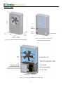
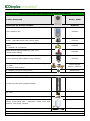
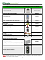
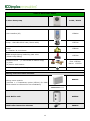
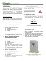
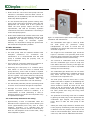
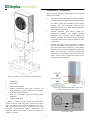
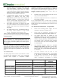
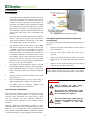
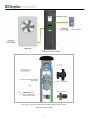
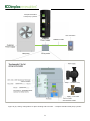
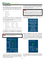
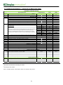
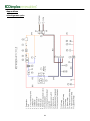
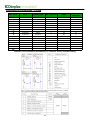
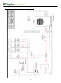
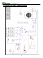
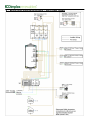
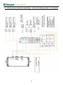
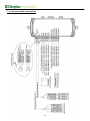
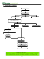
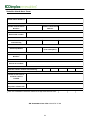
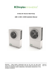
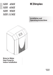
A-Class Air Source Heat Pump A12M / A16M: Installation Manual IMPORTANT – THIS MANUAL MUST BE LEFT WITH THE USER AFTER INSTALLATION, INCLUDING THE HAND-OVER FORM AT THE BACK, WHERE THE INSTALLER SHOULD RECORD KEY INFORMATION DURING COMMISSIONING. 8/60472/0 Issue 1.03 Overall View Water Outlet Water Inlet Name Plate Figure 1(b): Position of heat pump Figure 1(a): Outer dimensions of heat pump name plate and connections Figure 1 (c) : Internal components of heat pump ii Contents Introduction 1 Scope of Delivery 1 Pre-Installation Advice 1 3.1 Warnings 1 3.1.1 Handling & Transport 1 3.1.2 General 2 3.1.3 Safety 2 3.1.4 Maintenance 2 3.1.5 Electrical Warnings 2 3.2 Intended Use 2 3.3 Legal 2 3.4 Heat Pump Sizing 3 3.5 Site Selection 3 3.5.1 Location of Heat Pump 3 3.5.2 Heat Pump Placement and Fixing 3 3.6 Plumbing - Preparation 4 3.6.1 Buffer Tank 5 3.7 Electrical Connections - Preparation 5 Installation 6 4.1 Plumbing 6 4.2 Electrical Connections 6 4.3 Opening the Heat Pump for Electrical Connections 6 4.3.1 Heat Pump Electrical Connections 11 Set to Work 11 5.1 Location of Indoor Components 11 5.2 Set to Work 11 5.3 Opening the User Interface 11 5.4 Using the User Interface 12 Getting Started 13 Commissioning 14 iii 7.1 General/Schematic 14 7.2 Waterside Check 14 7.2.2 Temperature Check 15 7.3 Electrical Connections 15 7.4 Water Flow Check 15 7.5 DHW Setup 16 7.5.1 Electrical Connections (DHW) 16 7.5.2 DHW Test 17 7.6 Disinfection 17 7.7 Heating Curves 18 8 Additional Installer Menu Options 19 8.1 Message Log 19 8.2 Output Tests 19 8.3 Defrost 19 8.4 Operating Data 19 8.5 History 19 9 Service Menu 19 10 System Health Check/Maintenance 20 11 Technical Specifications 21 12 Appendices 22 A - Refrigerant Cycle 22 B - Schematic Zone Diagrams - Legend 23 C - Schematics 1, 2, 3 & 4: Space Heating Only 24 D - Schematics 5, 6, 7 & 8: Zone Space Heating & Domestic Hot Water (DHW) 25 E - Schematics 9, 10, 11 & 12: Bivalent Space Heating 26 F - Schematics 13, 14, 15 & 16: Bivalent Zone Space Heating & DHW 27 G - Wiring Centre Electrical Connections - A Class Cylinder 28 H - Wiring Centre Electrical Connections - non A Class Cylinder/no cylinder 29 I - Controller Cable Connections 30 J - Installer Menu Flowchart 31 Installer Handover Form 32 Declaration of Conformity 33 iv Pack 1: SPACE HEATING AND DIMPLEX A-Class CYLINDER A Class Heat pump A12M / A16M Hydraulics Kit A which includes: ACCHYPK User interface (UI) 1754600 Pump - UPM GEO 25-85 180 (70mm cable) 1755740 2 x Circulation Pump Gate Valve 11/2 "swivel to 28mm comp 2 x Washer 30.1x21x2mm 1756090 ERES straight Spring loaded by-pass valve (22mm comp fitting) 1755780 3 port diverting valve (28mm comp. fittings) 1755750 Isolation valves (1” swivel BSP to 28mm comp) (1) Flow (2) Return with strainer (1) (2) 4 x Blanking plugs for lifting holes Flow 1755760 Return 1755770 4592624105 Installation and User manuals Dimplex A Class DHW Cylinder Kit which includes: A Class Cylinder with integrated buffer Air vent Drain Safety group DHW side - expansion vessel, hose and bracket, inlet group, tundish 3 x Copper pipes – Pump to buffer/cylinder Pipe connections to coil, pipe, drain and vent, Pipe connections to pump A Class Cylinder Installation and User instructions v Pack 2: SPACE HEATING AND DIMPLEX STANDARD HEAT PUMP CYLINDER A Class Heat pump A12M / A16M Hydraulics Kit A which includes: ACCHYPK User interface (UI) 1754600 Pump - UPM GEO 25-85 180 (70mm cable) 1755740 2 x Circulation Pump Gate Valve 1"1/2 swivel to 28mm comp 2 x Washer 30.1x21x2mm 1756090 ERES straight Spring loaded by-pass valve (22mm comp fitting) 1755780 3 port diverting valve (28mm comp. fittings) 1755750 Isolation valves (1” swivel BSP to 28mm comp) (1) Flow (2) Return with strainer 4 x Blanking plugs for lifting holes (1) (2) Flow 1755760 Return 1755770 4592624105 Installation and User manuals Wiring centre Kit which includes: Wiring centre module (including 1 x Temperature probe (NTC10) for DHW) 049162 Dimplex Standard Cylinder NOTE: Cylinder required for Pack 2 installation, please see Dimplex EC-Eau Cylinder manual for range of non A-Class cylinders available. vi Pack 3: SPACE HEATING ONLY A Class Heat pump A12M / A16M Hydraulics Kit B which includes: ACSHYPK User interface (UI) 1754600 Pump - UPM GEO 25-85 180 (70mm cable) 1755740 2 x Circulation Pump Valve Gate 1"1/2 swivel to 28mm comp 2 x Washer 30.1x21x2mm 1756090 ERES straight Spring loaded by-pass valve (22mm comp fitting) 1755780 Isolation valves - (1” swivel BSP to 28mm comp) (1) Flow (2) Return with strainer 4 x Blanking plugs for lifting holes (1) (2) Flow 1755760 Return 1755770 4592624105 Installation and User manuals Wiring centre Kit which includes: Wiring centre module (includes 1 x Temperature probe (NTC10) for DHW which should be removed for this installation) 049162 100L Buffer tank 025586 2kW buffer immersion element 363610 vii 1 Introduction Thank you for choosing a Dimplex Heat Pump. The Dimplex A-Class heat pump provides outstanding performance to maximise year-round efficiency, regardless of the weather conditions. It can deliver high output and high temperatures even at low outside air temperatures of -7°C. The sophisticated controller makes the system easy to use and there are many more technological innovations including a scroll compressor that uses enhanced vapour injection. Details of all packs/components provided are shown on pages v-vii of this manual. The ACSHYPK hydraulics kit B contains all of the necessary hydraulic components. 3 Pre-Installation Advice ! 3.1 Warnings 3.1.1 Handling and Transport When transporting, moving and installing the heat pump, ensure that it is not tilted by more than 45° (in any direction), for any prolonged period of time. 2 Scope of delivery Please ensure you check the scope of delivery before signing any delivery documentation. Below is a guideline checklist for what should be contained in each pack. Claims for missing or damaged parts after signing for the delivery will not be accepted. 45 x. Ma There are 3 options to select from when installing a Dimplex Heat Pump: Pack 1 - Space heating and Dimplex AClass Cylinder This pack should contain four boxes; A separate wiring centre is not required as the wiring centre is built into the cylinder. The ACCHYPK hydraulics kit A contains all of the necessary hydraulic components. Pack 2 - Space heating and Dimplex Standard Heat Pump Cylinder This pack should contain five boxes; A separate wiring centre is required as the wiring centre is not built into the standard cylinder. The ACCHYPK hydraulics kit A contains all of the necessary hydraulic components. Pack 3 – Space heating only This pack should contain three boxes; x. 45 ° Figure 2: Allowable tilt angle during handling Do not attempt to lift the heat pump manually, as it weighs 130kg and should only be lifted using the appropriate lifting devices. Ensure that there is a clear pathway for a truck to deliver the heat pump as close to the selected location as possible. The installer must use a suitable lifting method, in accordance with health and safety regulations. Straps must also be used with the lifting rod to prevent the heat pump from toppling. Heat Pump ACCHYPK Hydraulics Kit A Cylinder Cylinder Accessories Wiring Centre Ma Tilt Angle Heat Pump ACCHYPK Hydraulics Kit A Cylinder Cylinder Accessories ° Heat Pump ACCHYPK Hydraulics Kit A Wiring Centre Accessories Figure 3: Handling of heat pump A separate wiring centre is required to wire the circulation pumps and controls. 1 return isolation valve provided in the hydraulics pack has a built in strainer to help prevent debris entering the condenser and must be fitted. 3.1.2 General Installation and any service work on the heat pump may only be performed by authorised and qualified installer and after-sales service technicians. NOTE: During the commissioning of the domestic hot water cylinder, ensure that the cylinder is full and no water is drawn from the cylinder as this will adversely affect the heat pumps operation. Additional heating may be required if the heat pump is intended to dry out a new or renovated building, as the initial heat load may be higher than the calculated load. 3.1.5 Electrical Warnings Before removing the cover of the heat pump, cylinder or wiring centre, ensure that all electrical circuits are isolated. Products not installed with the Dimplex hydraulics packs will not be supported by Dimplex. This includes but is not limited to thermal stores. Means for disconnection from the supply mains must be incorporated into the fixed wiring in accordance with the national wiring regulations. 3.1.3 Safety The heat pump contains refrigerant at high This device must be installed in accordance with pressure. Safety measures are in place to avoid system pressure build up. national wiring regulations. This device is suitable for mains connection only Stage 1: Pressure transducer stops compressor. (230V, 1P&N, 50Hz) and is not suitable for operation with an electrical generator or power modulator, due to possible effects on the quality of the electrical supply. Any attempt to do so will void warranty. Stage 2: Pressure switch switches heat pump off. All safety devices reset automatically. The heat pump has a multi-layered, software generated alarm management system. However, the overriding safety feature is the high pressure switch, which de-energises the main contactor supplying power, in accordance with EN378. The installation of a separate residual current device (RCD) having a rated residual operating current not exceeding 30mA is recommended. The local wiring regulations should always be This appliance can be used by children aged 8 followed paying particular attention to the mixing of low voltage and extra low voltage cabling. years and above and by persons with reduced physical, sensory or mental capabilities or lack of experience/knowledge, provided that they have been given supervision or instruction concerning the use of the appliance in a safe way and understand the hazards involved. NOTE: The digital inputs are volt free. If any voltage (such as a switch live 230V) is connected, irreparable damage will be caused to the wiring centre. Children must 3.2 Intended Use 3.1.4 Maintenance This device is only intended for domestic use. Any other use beyond that intended by the manufacturer is prohibited. This requires the user to abide by the manufacturer’s product information. Please refrain from tampering with or altering the device. not play with the appliance. Cleaning and user maintenance must not be carried out by children without supervision. If the heat pump may be disconnected from the power supply for prolonged periods of time, or where power supplies are susceptible to failure, antifreeze must be added to the system. 3.3 Legal The construction and design of the heat pump complies with all relevant EU directives (see CE declaration of conformity). Never use cleaning agents containing sand, soda, acid or chloride as these can damage surfaces/ components. When connecting the heat pump to the power supply, the relevant EN and IEC standards must be adhered to. Any further connection requirements stipulated by the network operation must also be observed. We recommend the installation of a suitable filtration protection system and the use of a corrosion additive for the heating system to prevent the formation of deposits (e.g. oxide and solids) in the condenser of the heat pump. The When connecting to the heating system all applicable regulations must also be adhered to. 2 3.4 Heat Pump Sizing Ensure that the correct size heat pump has been selected in accordance with the latest version of MIS3005 (for UK installation) and with the Dimplex Heat Pump Planning Manual. If a non A-Class heat pump cylinder is being used, ensure that it has been accurately sized with the appropriate coil surface area of the cylinder to match the heat pump’s output and flow rate requirements, and that all necessary hydraulic connections have been considered in connecting it to the heat pump system. Ensure that suitable heat emitters have been sized in accordance with the Heat Emitter Guide (for UK installation) and selected ensuring a low flow temperature design. To maximise system efficiency it is important to design the system with the lowest flow temperature possible. Figure 4: Required free space around heat pump for ventilation and maintenance The condensate drain pipe is coiled up inside the heat pump for protection during transportation. In order to access this for installation, the panels will need to be removed, as shown in figure 9. 3.5 Site Selection 3.5.1 Location of Heat Pump The heat pump must be installed outdoors with adequate clearances for ventilation and maintenance. It is recommended that the heat pump is installed along the property wall, as shown in figure 4. The length of the condensate pipe should be kept to a minimum. This prevents parts of the pipe from being exposed to the elements, which could contribute to issues with freezing. The removal of condensate must be secured and the condensate pipe must be kept free from debris and frost. Freezing of this pipe due to incorrect installation can result in irreparable damage and void warranty. There must be a minimum distance of 1000mm in front of the fan to prevent air re-circulation. Positioning the heat pump in a confined space, frost hollow or well will result in reduced heat pump efficiency, as the cold air which is expelled by the fan cannot disperse and may be drawn back into the system. This means that the heat pump may be operating using a lower inlet temperature than what is actually available from the thermostat, and will therefore run less efficiently. The condensate pipe should not run into sewer pipe unless a suitable trap is installed, as fumes may travel into the heat pump and cause corrosion to the evaporator coil. The heat pump must be fixed onto a level, stable base that is capable of withstanding the unit’s weight of 130kg, with a minimum of 50mm clearance around all sides of the heat pump. It can be secured on the inside of the heat pump with M10 anchor bolts, by removing the outer panels and using the fixing holes shown in figures 5. The positions of the fixing holes can be located The fan should preferably not face prevailing winds to ensure correct air flow through the evaporator. Although the heat pump is within noise and vibration regulations outlined in MCS007, it is recommended to avoid positioning it close to bedroom windows, as the fan and compressor may be operational at night. by placing the heat pump on the plinth with the condensate pipe aligned, and marking the holes. Move or slide the heat pump to drill holes. 3.5.2 Heat Pump Placement and Fixing Approximately 2 litres of condensate water are drained from the system every time a defrost cycle occurs (approximately once every hour in colder weather). Therefore, it is essential that the condensate pipe is fed into a drain or soak away to allow for safe disposal of the excess water, away from footpaths or patios. 3 Ideally the heat pump should be located close to the property. Positioning of the heat pump at a distance from the property will result in the need for extra insulated pipe, which will lead to extra cost, and result in additional heat losses. 3.6 Plumbing – Preparation When selecting piping to install with the heat pump please ensure that: The pipe sizes are adequate to allow the correct nominal water flow rate through the heat pump. The safety group and expansion vessel (space heating side) are accurately sized by the installer based on the system volume (these are not supplied by Dimplex). External pipework and valves should be adequately insulated with vapour resistant insulation and protected against damage to prevent excessive heat losses. All joints should be suitably sealed and exposed pipework must be avoided. Existing hot water systems should be flushed prior to connection to the heat pump to remove all contaminants and impurities, in accordance with the latest version of MIS3005. Ensure the water out and water in pipes are positioned correctly for connection to the heat pump as shown on the label in figure 6(b) and on the back of the heat pump 6(a). Figure 5: Position of hole fixings and condensate drain Heat pump Base plate Solid concrete plinth Flexible condensate drain pipe Ø 35mm, 1m long (supplied), should be fitted to 0.5m below ground to allow soakaway Hole for condensate drain (minimum 40mm diameter) Hole for cable feed Figure 6(a): Plumbing with isolation valve with strainer to be fitted to return pipe In figure 5, there are four fixing holes Ø 16mm (centre 140mm from long edge, 55mm from short edge and 190mm from centre to centre for each pair) and one centre hole for the condensate pipe. The minimum recommended plinth dimensions are 1000mm (500mm to centre) x 470mm (235mm to centre) x 100mm. Figure 6(b): Label 4 Isolation valves (non-return valve and ball valve with strainer), supplied in the Dimplex heat pump hydraulics pack, allow the strainer to be removed and cleaned without having to drain the system. Installation of these valves is discussed in more detail in section 4.2. If multiple heat emitter circuits are installed, operating at different flow and return temperatures (such as under floor heating and standard radiators), a mixing valve must be used to prevent high temperature water from entering the under floor heating manifold. conditions. Therefore, it is necessary to connect a buffer tank in series with the heat pump, as shown in the hydraulic schematic diagrams (Appendix B). The Dimplex A-Class cylinder range come with an integrated buffer tank, which; carry out successful defrost. Increases compressor life due to reduction in the number of starts. It is recommended that a buffer with a heating element/immersion is used as it may be required if initial start-up and commissioning are carried out in cold weather. Zone valves and pumps, if required, are sized up by the installers to suit plumbing layout. A suitable relay needs to be selected to energise the pump. Provides some energy storage for the unit to 3.7 Electrical connections - Preparation EC pumps must not be connected directly to Ensure the incoming power supply and the distribution board are suitably rated. the wiring centre because of high inrush current. An auxiliary relay must be used. Ensure that the regulations specified by the local electricity supplier have been adhered to. Table 1 shows guidelines for the maximum length of pipe allowed to achieve nominal flow rates, depending on pipe diameter. The supply cable must be suitable for the installation location and sized to meet the requirements of national wiring regulations for current carrying capacity, disconnection time and voltage drop; a minimum cross sectional area of 6mm² steel wire armoured (SWA) cable is recommended. NOTE: Not all types of pipe will have the same internal diameter, e.g. multi-layered/plastic pipes will have a thicker wall so the guidelines set out in table 1 will not apply. Microbore (8mm) and 15mm pipe is not suitable. As a rule of thumb, the equivalent straight length (L [mm]) of each elbow is found by multiplying the outer diameter of the pipe (D [mm]) by 30, e.g. 4 elbows of diameter 22mm pipe is equivalent to 2.5m of 22mm pipe. 3.6.1 Buffer tank The required controller cable is a shielded MODBUS cable RS485, such as a 4 core 1mm² 24 AWG (Nominal impedance 120Ω) Foil and Braid, which can be purchased from Dimplex as an accessory. The heat pump uses a reverse cycle defrost in order to defrost the evaporator, which is an automated process when required in cold/moist weather The user interface can be used as the temperature thermostat in zone 1. The location of the UI/zone 1 should be discussed before installation with the end user. For multiple zones, mechanical thermostats or NTC10 Space Heating Only DHW with A-Class Cylinder Water Flow Rate @ 2100 l/h (nominal) @ 1800 l/h (typical) Associated Head Available 14 kPa 18kPa Maximum Equivalent Length (m)~ Diameter (mm) Internal Diameter (mm) 22* 19.8 7 11 28^ 25.6 23 38 32 29.6 46 77 Table 1: Maximum Equivalent Length for Copper Pipe *Only suitable for special conditions ^Recommended pipe diameter 5 ~ Assuming straight length with no incidents (e.g. elbows, tees) 4 Installation 4.1 Plumbing The system must be filled and flushed with clean fresh water to ensure the removal of all the air from the installation. Air bleed points must be installed at every high point in the system; in particular, the installer must remember to install an air bleed on the heat pump pipe if it is a local high point since there is no air bleed point on the condenser. Dimplex recommend the use of a power flush and purge cart to facilitate this process. Figure 7: Flow and return valves Flow and return isolation valves (Flow 1755760, 4.3 Opening the Heat Pump for Electrical Connections Return 1755770) and piping must be fitted to each of the condenser connections on the back of the heat pump, as shown in figure 7. To open the heat pump, follow the procedure shown in figure 9: The isolation valve on the return is also fitted with a non-return valve (built into ‘175770’) and a strainer (included in the Dimplex heat pump hydraulics pack). This means that in order to clean the strainer, the system does not have to be drained. Instead, it is possible just to close the isolation valves on the flow and return and remove the strainer. This way, the only water that will be lost from the system is that between the non-return valve and strainer. The strainer must be fitted in order to prevent contamination of the condenser heat exchanger. If an alternative strainer is used, it must be at least 7 microns in size and connected with ball valves. Unscrew 2 screws holding bottom panel, using a PZ2 screwdriver. Pull the front panel down and then out to remove. Unscrew 5 screws holding the front cover of the electrical box to open and pull down towards you. Remove 2 PZ2 screws holding the door flap in place to access cable connections. NOTE: Follow steps in reverse order to close the heat pump. When closing the heat pump front panel, ensure that the top and bottom panels are interlocked. System pressure must be checked once valves are re-opened. Direct condensate drain pipe to soak away or drain, as illustrated in figure 5 in section 3.5.2. All piping must be properly insulated external length kept to a minimum. WARNINGS: and ! Before opening the heat pump, ensure all circuits are isolated. ! Ensure that the components in the electrical box do not get wet when the electrical box is opened. 4.2 Electrical connections The heat pump system consists of the heat pump, wiring centre and user interface. If a Dimplex A-Class cylinder is also purchased, the wiring centre is built into the cylinder. The user interface contains a thermostat and is sufficient if one heating zone is present. ! Optional, additional temperature probes or room thermostats are required for additional heating zones. Figure 8 (a) – (c) shows the wiring configuration of the 3 different installation options (outlined in section 2: Scope of Delivery, at the beginning of this manual). 6 The main 230V power cable must be supplied via a suitable sized exterior isolator, lockable in the OFF position. MODBUS Cable User Interface DI01 DI02 DI03 DI04 DI05 NT C—D HW NTC-Zone 1 NTC-Zone 2 NTC-Zone 3 NTC-Zone 4 LIVE EARTH NEUTRAL RELAY RELAY RELAY RELAY RELAY 1 2 3 4 5 RELAY 6 RELAY 7 RELAY 8 Figure 8 (a): Wiring configuration of space heating and hot water Dimplex A-Class cylinder 7 Dimplex Standard heat pump cylinder User Interface MODBUS Cable DI01 LIVE EARTH NEUTRAL DI02 DI03 DI04 DI05 NTC—DHW NTC-Zone NTC-Zone 1 RELAY RELAY RELAY RELAY RELAY 1 2 3 4 5 2 NTC-Zone 3 NTC-Zone 4 RELAY 6 RELAY 7 RELAY 8 Figure 8 (b): Wiring configuration of space heating and hot water – Dimplex standard heat pump cylinder 8 MODBUS Cable User Interface DI01 LIVE EARTH NEUTRAL DI02 DI03 DI04 DI05 RELAY RELAY RELAY RELAY RELAY NTC—DHW NTC-Zone NTC-Zone 1 1 2 3 4 5 2 NTC-Zone 3 NTC-Zone 4 RELAY 6 RELAY 7 RELAY 8 Figure 8 (c): Wiring configuration of space heating only 9 Figure 9: Opening the casing to fit electrical connections NOTE: Please ensure that opening for cable access is not left open Figure 10: Heat pump electrical connections 10 4.3.1 Heat pump electrical connection The wiring centre or DHW cylinder is connected to the mains power supply. The Modbus network is complete and the UI and the heat pump are connected to the wiring centre or DHW cylinder. To make electrical connections to the heat pump: Feed power cable and controller cable through gland at the back of the base panel. Remove the cable access cover and using the opening in the base panel for access, pull power cable and controller cable through the two cable glands in base panel and through the two glands on the side of the electric box. Once cables have been routed through the base glands, close the access cover. Once the connections have been made and the power supplies have been switched on, the system may take a couple of minutes to start up. 5.3 Opening the User Interface It is recommended to connect the Modbus cable in daisy-chain series (as shown in figure 11) from the heat pump on to the wiring centre and then on to the UI. Allow sufficient cable to ensure the connections are not strained when the cover is opened. Armoured cable must be stripped once it has been pulled through the base cable gland in order to pass through cable gland in side panel of the electrical box. If it is deemed necessary to install the Modbus cable in a different order, please ensure that the jumper is put into the OFF position on the UI and that the last component in the network has a jumper in the ON position, as shown in figure 13. Connect power cable and controller cable as shown in figure 10. Where stranded cable (e.g. Tri rated singles) has been used, a ferrule must be fitted before inserting into the push connections. The cover of the UI must be removed in order to move the jumper. To remove the cover; Unscrew the screw at the bottom of the UI and lift the cover and rotary dial. To replace; The controller (Modbus) cable is then connected from the heat pump to the wiring centre (see wiring diagrams in Appendix C and D). 5 Set To Work 5.1 Location of indoor components Location of UI and room thermostats: Position the rotary dial over the holding pin on the board, ensuring the two are lined up correctly. Replace cover and bottom screw. Ensure that rotary dial is tested and working once cover has been replaced. The user interface and room thermostats should be installed indoors in a location that is out of reach of children, but where the LCD display can be easily seen (usually 1.2m – 1.7m from the floor). The controller and thermostats should be installed on internal walls in living area to reflect the correct temperature, and away from direct sunlight, drafts (windows and doors) and heat emitters. Location of wiring centre: If a Dimplex A-Class cylinder is used, the wiring centre is built in and pre-wired. If a non A-Class cylinder is used, it is recommended to install the wiring centre in close proximity to the cylinder. Jumper 5.2 Set to work When starting up the heat pump you must first ensure that; All covers are replaced. The heat pump isolator switch is switched on. The heat pump is connected to the mains power supply via a separate suitable circuit breaker and RDC protection. Figure 13: Jumper in the ON position on water module 11 Start End Heat Pump Wiring Centre User Interface (Jumper ON) (Jumper OFF) (Jumper ON) MODBUS cable Figure 11: Recommended MODBUS cable configuration Start End Heat Pump User Interface Wiring Centre (Jumper ON) (Jumper OFF) (Jumper ON) MODBUS cable Figure 12: If not using the recommended MODBUS cable configuration, the jumper should be located at the beginning and end of the network Jumper Jumper Figure 14: Jumper in the OFF position on water module Figure 15: Jumper in the ON position on user interface (UI) 5.4 Using the User Interface Select – click middle of the rotary dial (Enter/Confirm) Change selected value – turn the rotary dial to desired value Confirm change – click middle of rotary dial (Enter/Confirm) Back up one level – click small button (Escape) Figure 16: User interface (UI) 12 6 Getting Started pressing in the dial to select as before. You will then need to input 55 (commissioning menu code) to bring up the installer menu. When switching on the heat pump for the first time, and after the start up sequence, you will be greeted by the home screen, shown in figure 17. When you enter the installer menu, you will see the option for ‘Language Selection’, as shown in figure 19 (a). As you progress through the set up process, other options will become available on this menu. Figure 19(a): Initial Installer Menu screen Select the ‘Language Selection’ option, which will bring you to the ‘Start Guide’ screen (shown in figure 19(b)). Selecting ‘UK’ will bring you back to the Installer Menu, which will now display the ‘Commissioning’ option (shown in figure 19(c)). INFORMATION MENU Figure 17: Home Screen If the heat pump is already switched on but you wish to make changes to the settings, you may need to press confirm in order to go from the screensaver to the home screen. To access the Installer Menu, you must select the information menu, which can be done by turning the rotary dial to navigate, then pressing it in to select an option. Once you have entered the information menu, you must select ‘Login’, as shown in figure 18. NOTE: You will not be able to access any other options on the home screen, except the information menu, until the heat pump has been commissioned. Figure 19(b): Start Guide screen Select ‘Commissioning’ to begin and follow the step by step guide on the user interface, which will take you through all necessary steps of commissioning. Instructions for commissioning are also detailed in section 7. Figure 18: Information Menu showing Login option When using the ‘Login’ function, input the access code supplied to you during training (22 - Installer) by turning the dial to scroll through numbers, then 13 7 Commissioning 7.2 Waterside check Select ‘Commissioning’ to begin and follow the instructions on the system controller. The commissioning routine will take you through a number of checks and tests to complete the installation. When you finish using each submenu in the commissioning process, selecting ‘Next’ will take you back to the main Commissioning menu, where a new submenu will be available (figure 19(c)). The ‘Waterside Check’ menu allows you to select whether temperature control is based on the flow or return temperature, as shown in figure 22. This will apply to heating curves, as discussed in section 7.1.9. Figure 19(c): Installer Menu with Commissioning option after Language Selection is complete 7.1 General/Schematic Figure 22: Temperature Control screen In some cases, it may be necessary to carry out checks on individual components of the heating system before beginning the commissioning routine. Accessing General/Schematic menu allows you to set the date and time, and the level of access allowed. It is generally always recommended to set the temperature control based on the return temperature, unless it is necessary to use flow temperature instead for a particular set up. Selecting ‘Next’ will bring you to the waterside checks menu (figure 23). Selecting ‘Next’ will bring you to the Schematic menu, as shown in figure 20 and 21, Once you have selected a schematic zone diagram, a number of other options will become available in the main Installer menu. Please see Appendix B for full Schematic diagram details. Figure 23: Waterside Check screen A number of waterside checks must be carried out as part of commissioning, and must be ticked as completed in the Waterside check menu: Figure 20: General Settings Figure 21: Schematic Menu NOTE: Once you have completed the schematic selection, you can access the following menus by escaping to the upper level Installer menu: Message log History 14 The system must be flushed. The strainer must be fitted to the return pipe. The system must be pressurized (You must enter the system pressure). The system must be fully bled. The expansion vessel must be fitted Membrane pressure adjusted if required. must be checked and 7.3 Electrical connections (SH) When checks are completed and ‘Next’ is selected, the type of temperature measurement devices to be used in each heating zone must also be selected: This menu provides a list of electrical connections that should be made prior to commissioning for space heating. The list is based on the schematic zone diagram selected and also the type of temperature devices that will be used in each zone. Once you have confirmed all checks and select ‘Next’, you will return to the commissioning menu where you can now access the ‘Water flow check’ menu. Figure 24: Temperature Measurement Device screen User Interface (usually in zone 1 – heating system controller) Temperature probe (option for temperature probe 1 to 3, for additional zones). Mechanical thermostat (option for mechanical stat 1 to 3, for additional zones). Figure 26: Electrical Connections screen NOTE: If these steps are confirmed on the controller during commissioning but haven’t been carried out, any failure in the system will be outside of warranty. Using a mechanical stat limits the level of heating control on the zone from the UI. Heating in zones using temperature probes can be fully controlled using the UI. Selecting ‘Next’ will bring you to the ‘Temperature check’ menu. NOTE: If any changes must be made to the commissioning configuration (e.g. selecting a different probe), it is strongly advised that a factory reset is performed and that the heat pump is re-commissioned entirely. Changing individual settings during the commissioning process may cause commands to be ignored or cause the heat pump to stop working correctly. 7.2.2 Temperature Check This screen displays the temperatures currently being read by all thermostats. It is the duty of the installer to ensure that all thermostats are installed and working correctly, and the boxes on this menu should not be ticked unless all displayed temperatures have been confirmed to be within an acceptable, accurate and expected range. 7.4 Water flow check Select ‘Run Test’ to begin water flow check. The circulation pump will be tested first by running it for 30 seconds. When the timer reaches zero, the pump will continue to run in 30 second bursts until flow is confirmed, which allows time for the installer to check that the pump is working. Once you have checked that flow is detected, click ‘Continue’ to confirm that the pump is working correctly. Do not confirm that the pump is working in this menu unless you have physically checked it, as the UI requires your input and does not detect this automatically. Once this is successful, the compressor will be run for 5 minutes. As the test runs, the screen will give you information on the status of the heat pump and the time remaining on the test. If you do not have flow or if there is a problem, you can stop the test. Figure 25: Temperature Check screen 15 7.5 DHW setup If there is no flow at all, a high pressure fault will appear on the UI screen and the commissioning will be aborted. Once the test is completed, you will see one of three messages: 1. 2. 3. Before commissioning the DHW, a number of checks must be carried out, as shown in figure 29. When you have ticked each box to confirm each DHW check, ‘Next’ will bring you back to the installer menu, where you can now select ‘Electrical Connections (DHW)’. No flow detected Flow too low Flow detected NOTE: It is possible to use space heating without completing the DHW setup. This can be done by selecting ‘N’ on the DHW setup screen where it asks if the cylinder is connected (see figure 29). When the cylinder is ready, it will be necessary to return to this step of the commissioning and select ‘Y’ instead to set up domestic hot water. Figure 27: Water Flow Check If you see message 1 or 2, you must carry out the changes recommended on the screen and repeat the test. There will be a time delay before you can restart the test. When you see the screen shown in figure 28, with the pump highlighted in green, flow has been detected and the compressor test is complete. NOTE: for safety reasons, if the pressure exceeds 38 bar/temperature exceeds 60°C, the commissioning will also be aborted. Figure 29: DHW Set-up screen 7.5.1 Electrical connections (DHW) This menu provides a list of electrical connections that should be made prior to commissioning the domestic hot water cylinder. You must check and confirm all connections in order to make the ‘DHW Test’ available in the installer menu. Figure 28: Successful Compressor Test You will receive the status ‘Waterside is OK’ when the waterside checks are completed. Selecting ‘Next’ brings you to the Electrical Connections menu. If carrying out start up in cold weather, start by heating the buffer. Once it reaches the required temperature open each zone slowly and in series, especially for under floor heating. Figure 30: Electrical Connections screen (DHW) If you have selected Schematic 1 or 3 (Space heating only or Bivalent space heating), move now to section 7.1.9 ‘Heating Curves’ to complete the commissioning process. NOTE: Once you have completed the Electrical connections (SH) checklist, you can access the following menus by escaping to the upper level Installer menu: NOTE: If you leave the commissioning menu before you successfully complete commissioning, all previous information entered will be saved and completed menus will be highlighted in green. 16 Message log Operating data Output tests History 7.5.2 DHW Test Before you run the DHW test, you will be asked to check that the valve (figure 31) is in the DHW position, as shown on the screen in figure 32. Check that the red actuator marker changes to the correct position. When you have completed the valve check and select ‘Next’, you will see the DHW test screen, which informs that the test can take up to 90 minutes. Selecting ‘Run test’ begins the DHW test and shows you the time remaining. During the DHW test, it will not be possible to run a defrost cycle. Figure 33(b): DHW Test Complete screen Figure 31: Valve (DHW) Figure 33(c): DHW test screen (the test can be postponed or stopped here) Figure 32: Valve Check screen 7.6 Disinfection Figure 33(a): DHW Test Failed The temperature and frequency of the disinfection cycle can be adjusted in this menu. If the temperature is set to higher than the heat pump can achieve, the screen shown in figure 34 will appear which notifies that the immersion heated will be used to reach the disinfection temperature. If the test fails, you will see the screen shown in figure 33(a), which provides information on why the test failed, and advice on checks to carry out. If the test is complete and has been successful, you will see the screen shown in figure 33(b), which shows the maximum temperature that the cylinder can achieve. NOTE: It is possible to postpone the DHW test if necessary (for example, to run a defrost, because of time constraints or due to a larger cylinder), by selecting ‘Finish’ on the DHW test screen as shown in figure 33(c). If the test is postponed, DHW can still be used. Selecting ‘Stop test’ will cancel the test completely. If the DHW test has been cancelled rather than postponed, the information displayed on the set temperature menu for DHW will not be correct (the immersion will not be used until the maximum temperature achievable by the heat pump has been reached). Figure 34: Disinfection Set-up screen 17 7.7 Heating curves The red line indicates the temperature that the water will be heated to, based on the outdoor temperatures. The ‘Default’ option will reset the pre-defined values. Set will save entered values. When selecting heating curves, you will do so zone by zone. Selecting the zone and pressing ‘Next’ will allow you to select the kind of heat emitters that are in place in the selected zone. The four heating curves are for: Smart Rad Under floor Standard Rad Custom NOTE: If the heat pump is in “ON” mode and the maximum outside temperature is reached, the heat pump will revert to and maintain the set back temperature. To prevent this, it is possible to set your summer temperature (green line) at a higher value (the default outside ambient setting is 18°C). To complete commissioning, you must select the ‘Setup complete’ submenu in the installer menu, as shown in figure 36: Selecting Smart Rad, Underfloor or Standard Rad and then selecting ‘Edit’ will bring you to a default heating curve for the selected emitter. Selecting ‘Next’ will select the default heating curve. The pre-defined curves have recommended temperature ranges for each heat emitter; Smart Rad Max 48 Min 35 Under floor Max 30 Min 25 Standard Rad Max 55 Min 45 A fourth option, ‘Custom’, provides a flat line curve. The values that generate the heating curve graph can be changed, by selecting the corresponding temperature box and adjusting the temperature, as shown in figure 35. Figure 36: Full Commissioning menu When commissioning has been successfully completed, you will see the screen shown in figure 37. Selecting ‘Automatic’ will activate all settings, where as selecting ’Standby’ will enable the heat pump only to carry out the defrost function. The default setting for the heat pump is OFF. To turn on the heat pump, you must return to the home screen to access the user menu. NOTE: Pre-defined heating curves should only be changed if the heat pump does not achieve the predefined, recommended temperatures. Figure 37: Commissioning Complete Figure 35: Smart Rad Heating Curve screen For further information on end user controller instructions please see ‘A-Class Air Source Heat Pump User Guide supplied in the Hydraulics Pack with this manual. The green line on the right indicates the maximum outdoor temperature at which the heat pump stops running. The yellow line on the left indicates the minimum outdoor temperature at which the bivalent heating system starts working. 18 8 Additional Installer Menu Options The relays which control the immersion and backup heater/buffer use an electric interlocking system, and therefore R7 and R8 must be used together in order for the backup heater to function. Testing these relays individually will not reflect this. Once the commissioning process has been completed, if you return to the installer menu there will be various other options now available, as outlined in this section. 8.3 Defrost 8.1 Message log Before running a manual defrost cycle you must ensure the buffer has been isolated from the heating, as stated by the message on the UI. Selecting ‘Start Defrost’ begins the defrost cycle. The defrost screen will state the time remaining in the defrost cycle. The message log menu provides a list of all errors that have taken place, including the date and time when they occurred. Selecting an individual error code will provide more information on the type of error that occurred if an SD card is present. Active error messages will show a ticked box. A heating water return temperature of ≥18°C is required for proper defrosting of the evaporator. Figure 38 shows the list of errors shown in the ‘messagelist’ menu. When a new error occurs, it will appear at the top of the list. Up to 20 errors can be shown on the list at once, then, if another error occurs, the oldest error will be pushed off the list to make room for the new error. If the same error message is being displayed more than once, it may be necessary to check back through some of the older error messages in order to find the cause of the problem. 8.4 Operating data The operating data menu provides a list of all the system parameters, such as all temperatures, including each zone set and actual temperatures, flow rate, and heat pump status. If an SD card is present, this data will be recorded to every message listed. 8.5 History NOTE: If the same error occurs 10 times or more in succession, the lock out feature on the compressor will be triggered. In order to resolve this, the power to the compressor will have to be turned off and on again. The History menu shows the temporary run time history of the components of the system. These values can be reset in order to record run times over a certain time period. Selecting ‘Next’ brings you to the permanent run time history which cannot be reset. 9 Service Menu The service menu can be accessed, in a similar manner to the installation menu, by inputting the installer menu code (22) and then using the ’Login’ access code 998. Please see ‘A Class Air Source Heat Pump A12M/A16M: Service Manual’ for more details. Figure 38: Message log screen Figure 39: Output Tests screen 8.2 Output Tests The output tests menu allows you to turn ON/OFF tests on individual components of the system, as shown in figure 39, and can be accessed once Electrical Connections (Space Heating) are confirmed. LOGIN 22, THEN 998 Figure 40: Information screen Login for Service Menu NOTE: For successful commissioning you MUST follow through the menu until you see the screen shown in figure 39. If you do not see this screen, commissioning has not been successful and will void warranty of the heat pump. 19 10 System health check/maintenance Heat pump: Is the fan clear from debris? Is the tray clear from debris? Is the condensate drain clear from debris? Is the evaporator coil clean? Are all of the outer panels secure? Electrical: Is the power cable firmly fixed? Is the earth wire connection secure? Is the supply voltage correct? Hydraulics: Is the system sufficiently pressurized? Are there any leaks in the system? Is the filter clear of debris? NOTE: It is recommended that the strainer is checked and cleaned 24 hours after commissioning, and regularly within the first weeks of operation. Indoor settings: Are the set temperatures and heating times suitable for the occupants? Is the building warm enough for the occupants or does the heating curve need to be adjusted? Is the UI screen working correctly? 20 11 Technical Specifications – A Class Air-to-Water Heat Pump 1 2 2.1 2.2 3 3.1 3.2 TECHNICAL SPECIFICATIONS Type and Order Code Units/Dimensions Design Degree of protection according to EN 029 for compact unit or heating element Installation location Performance Data Operating temperature limits: Heating water flow and return temperature °C Outside aire temperature °C A12M A16M IP 24 Outdoors IP 24 Outdoors Min/Max 25/65 -20/35 Min/Max 25/65 -20/35 Seasonal Performance Factor (SPF) for under floor at 35°C1 3.9 3.9 Seasonal Performance Factor (SPF) for radiators at 55°C1 3.6 3.6 Heating water temperature difference at standard rating condition A7 W35 K 5 at A7 W35 kW/--12/4.7 Heat Output/COP at A-2 W35 kW/--12/3.5 at A-7 W35 kW/--12/3 at A7 W55 kW/--12/3 These figures characterise the size and performance of the system according to at A-2 W55 kW/--12/2.5 EN 14511 with clean heat exchangers. Abbreviations have he following at A-7 W55 kW/--12/2.2 meaning, .g. A2/W35: Outside temperature 2°C and heating water supply at A7 W65 kW/--12/2.5 temperature 35°C. A2/W35 test takes into account defrosting as per EN 1411. at A-2 W65 kW/--12/2.0 at A-7 W65 kW/--12/1.8 * Performance at this point is optimised to match the building heat load and maximise the Seasonal performance factor. Sound Power Level 2 dB(A) Sound pressure level at 10m (heat pump positioned against wall) dB(A) Heating water flow rate @ A7 W35 (nominal),(minimum) Air flow @ A7 W35 Refrigerant; total filling weight Water capacity of stainless steel heat exchanger Polyol ester oil in compressor Dimensions, Connections and Weight 4.1 Device dimensions without connections H x W x L mm 4.2 Physical volume m³ 4.3 Device connections to heating system inch 4.4 Weight of the transportable unit(s) excluding packaging kg 5 Electrical Connection (heat pump) 5.1 Nominal voltage; fuse protection V/A 5.2 Nominal power consumption / current A7 W35 kW/A 5.3 Maximum power consumption / current A-2 W65 kW/A 5.4 Power factor A7 W35 / cos? A/--5.5 Electrical supply frequency Hz 5.6 Power input of integral fan @ A7 W353 W 6 Oher Design Characteristics 6.1 Defrosting Type of defrosting 6.2 Heating water in device protected against freezing by software 3.3 3.4 3.5 3.6 3.7 3.8 3.9 4 1 Calculated to EN15316 excluding hot water 2 According to EN 12102. 3 Fan is variable speed, rated input relates to nominal input power. 21 5 12/4.7 * 15.5/3.2 14.3/3 12/3 * 15.6/2.4 15.3/2.2 12/2.5* 15/1.99 15/1.8 64 64 40 40 (2.1/35),(1.2/20) (2.1/35),(1.2/20) 3700 3700 R410A/2.0 R410A/2.0 1 1 1.18 1.18 1571 x 932 x 401 1571 x 932 x 401 0.59 0.59 1" ext. thread 1" ext. thread 130 130 230/C 40 2.6/11 6.9/30 11/>0.95 50 60 Automatic Reverse cycle Yes 230/C 40 2.6/11 8.1/35 11/>0.95 50 60 Automatic Reverse cycle Yes Appendices A Refrigerant cycle 22 B Schematic zone diagrams – Legend No. on UI Code Heating type No. of Zones DHW 1 2 3 4 5 6 7 8 9 10 11 12 13 14 15 16 10200110 Mono 1 No 10200210 Mono 2 No 10200310 Mono 3 No 10200410 Mono 4 No 10220190 Mono 1 Yes 10220290 Mono 2 Yes 10220390 Mono 3 Yes 10220490 Mono 4 Yes 10300110 Bivalent 1 No 10300210 Bivalent 2 No 10300310 Bivalent 3 No 10300410 Bivalent 4 No 10310190 Bivalent 1 Yes 10310290 Bivalent 2 Yes 10310390 Bivalent 3 Yes 10310490 Bivalent 4 Yes Schematic diagram A A A A B B B B C C C C D D D D Table B: List of available Schematics for selection during Commissioning 23 C - Schematics 1, 2, 3 & 4: Space Heating Only 24 D – Schematics 5, 6, 7 & 8: Zone Space Heating & DHW 25 E - Schematics 9, 10, 11 & 12: Bivalent Space Heating 26 F - Schematics 13, 14, 15 & 16: Bivalent Zone Space Heating & DHW 27 G - Wiring centre electrical connections – with A Class cylinder 28 H - Wiring centre electrical connections – with non A Class cylinder / no cylinder 29 I - Controller cable connections 30 J - Installer Menu Flow Chart Language Selection Commissioning General/Schematic Waterside Checks Message List History Electrical Connections (Space Heating Only) Operating Data Waterflow Checks DHW Setup Electrical Connections (DHW) DHW Test Disinfection Heating Curves Zone Selection Heating Circuit Type Setup Complete ON/Automatic 31 Input/Output Tests Installer Hand-Over Form Installer Name & address: Installer Contact Phone Number: Installer Contact Email Address: MCS Installer number Date of installation / commissioning HP Serial Number (from nameplate): Heat Pump Model: Cylinder Model/Serial Number: Accessories installed: Schematic number used for commissioning: Details of zone control and heat emitters installed Any other relevant info Note: this installation manual needs to be left with the end user. UK Customer Care Line 0844 879 35 88 32 EC Declaration of Conformity GDC Group Limited, Millbrook House, Grange Drive, Hedge End, Southampton, Hants, SO302DF, United Kingdom Glen Dimplex Ltd Greenbank Industrial Estate, Rampart Road, Newry, Co. Down, BT34 2QU Manufacturer: Hereby certified that the following device(s) complies/comply with the applicable EU directives. This certification loses its validity if the device(s) is/are modified. Description: Heat Pump Type: Air – to – Water Model: A16M Model: A12M EC Directives: Low voltage directive 2006/95/EC EMC directive 2004/108/EC Pressure equipment directive 97/23/EC RoHS2 directive 2011/65/EU Applied Standards: EN 60335-1:2012; EN60335-2-40:2003+A11+A12+A1+corr.+A2:2009+AC:2010 EN55014-1:2006; EN55014-2:1997+A1:2001 EN61000-3-2:2006; EN61000-3-3:1995+A1:2001+A2:2005 EN378-1:2008+A1:2010; EN378-2:2008+A1:2009; EN378-3:2008; EN378-4:2008 EN 14511-1:2011; EN14511-2:2011; EN14511-3:2011; EN14511-4:2011 Conformity assessment procedure according to pressure equipment directive: Module A CE mark added: 2013 EC declaration of conformity issued on: 29 October 2013 Issue: 1.03 33