1
USER’S GUIDE
AGILENT 6010A, 6011A, 6012B,
6015A, 6023A and 6028A
DC AUTORANGING POWER SUPPLY
Agilent Part Number 5964-8120
Microfiche Part No. 5964-8121
Printed in Malaysia
September, 2004
CERTIFICATION
Agilent Technologies certifies that this product met its published specifications at time of shipment from the factory.
Agilent Technologies further certifies that its calibration measurements are traceable to the United States National
Bureau of Standards, to the extent allowed by the Bureau’s calibration facility, and to the calibration facilities of other
International Standards Organization members.
WARRANTY
The 601xA/B and 602xA Agilent Technologies hardware products are warranted against defects in material and
workmanship for a period of one year from date of delivery. Agilent software and firmware products, that are
designated by Agilent for use with a hardware product and when properly installed on that product, are warranted
not to fail to execute their programming instructions due to defects in material and workmanship for a period of 90
days from date of delivery. During the warranty period Agilent Technologies will, at its option, either repair or replace
products that prove to be defective. Agilent does not warrant that the operation for the software firmware, or
hardware shall be uninterrupted or error free.
For warranty service, with the exception of warranty options, this product must be returned to a service facility
designated by Agilent. Customer shall prepay shipping charges (and shall pay all duty and taxes) for products
returned to Agilent for warranty service. Except for products returned to a Customer from another country, Agilent
shall pay for return of products to the Customer.
Warranty services outside the country of initial purchase are included in Agilent's product price, only if Customer
pays Agilent international prices (defined as destination local currency price, or U.S. or Geneva Export price).
If Agilent is unable, within a reasonable time to repair or replace any product to condition as warranted, the
Customer shall be entitled to a refund of the purchase price upon return of the product to Agilent.
LIMITATION OF WARRANTY
The foregoing warranty shall not apply to defects resulting from improper or inadequate maintenance by the
Customer, Customer-supplied software or interfacing, unauthorized modification or misuse, operation outside of the
environmental specifications for the product, or improper site preparation and maintenance. NO OTHER
WARRANTY IS EXPRESSED OR IMPLIED. AGILENT SPECIFICALLY DISCLAIMS THE IMPLIED WARRANTIES
OF MERCHANTABILITY AND FITNESS FOR A PARTICULAR PURPOSE.
EXCLUSIVE REMEDIES
THE REMEDIES PROVIDED HEREIN ARE THE CUSTOMER'S SOLE AND EXCLUSIVE REMEDIES. AGILENT
SHALL NOT BE LIABLE FOR ANY DIRECT, INDIRECT, SPECIAL, INCIDENTAL, OR CONSEQUENTIAL
DAMAGES, WHETHER BASED ON CONTRACT, TORT, OR ANY OTHER LEGAL THEORY.
ASSISTANCE
The above statements apply only to the standard product warranty. Warranty options, extended support contacts,
product maintenance agreements and customer assistance agreements are also available. Contact your nearest
Agilent Technologies Sales and Service office for further information on Agilent's full line of Support Programs.
Copyright 1999 Agilent Technologies
2
Edition 1___January, 1999
Update 1___February, 2000
Update 2___September, 2004
Safety Summary
The following general safety precautions must be observed during all phases of operation of this instrument. Failure to
comply with these precautions or with specific warnings elsewhere in this manual violates safety standards of design,
manufacture, and intended use of the instrument. Agilent Technologies assumes no liability for the customer’s failure to
comply with these requirements.
GENERAL
This product is a Safety Class 1 instrument (provided with a protective earth terminal). The protective features of this
product may be impaired if it is used in a manner not specified in the operating instructions.
Any LEDs used in this product are Class 1 LEDs as per IEC 825-1.
This ISM device complies with Canadian ICES-001. Cet appareil ISM est conforme à la norme NMB-001 du Canada.
ENVIRONMENTAL CONDITIONS
This instrument is intended for indoor use in an installation category II, pollution degree 2 environment. It is designed to
operate at a maximum relative humidity of 95% and at altitudes of up to 2000 meters. Refer to the specifications tables for
the ac mains voltage requirements and ambient operating temperature range.
BEFORE APPLYING POWER
Verify that the product is set to match the available line voltage, the correct fuse is installed, and all safety precautions are
taken. Note the instrument’s external markings described under "Safety Symbols".
GROUND THE INSTRUMENT
To minimize shock hazard, the instrument chassis and cabinet must be connected to an electrical ground. The instrument
must be connected to the ac power supply mains through a three-conductor power cable, with the third wire firmly
connected to an electrical ground (safety ground) at the power outlet. For instruments designed to be hard-wired to the ac
power lines (supply mains), connect the protective earth terminal to a protective conductor before any other connection is
made. Any interruption of the protective (grounding) conductor or disconnection of the protective earth terminal will cause
a potential shock hazard that could result in personal injury. If the instrument is to be energized via an external
autotransformer for voltage reduction, be certain that the autotransformer common terminal is connected to the neutral
(earthed pole) of the ac power lines (supply mains).
ATTENTION: Un circuit de terre continu est essentiel en vue du fonctionnement sécuritaire de l’appareil. Ne
jamais mettre l’appareil en marche lorsque le conducteur de mise … la terre est d‚branch‚.
FUSES
Only fuses with the required rated current, voltage, and specified type (normal blow, time delay, etc.) should be used. Do
not use repaired fuses or short-circuited fuseholders. To do so could cause a shock or fire hazard.
DO NOT OPERATE IN AN EXPLOSIVE ATMOSPHERE
Do not operate the instrument in the presence of flammable gases or fumes.
KEEP AWAY FROM LIVE CIRCUITS
Operating personnel must not remove instrument covers. Component replacement and internal adjustments must be made
by qualified service personnel. Do not replace components with power cable connected. Under certain conditions,
dangerous voltages may exist even with the power cable removed. To avoid injuries, always disconnect power, discharge
circuits and remove external voltage sources before touching components.
DO NOT SERVICE OR ADJUST ALONE
Do not attempt internal service or adjustment unless another person, capable of rendering first aid and resuscitation, is
present.
DO NOT EXCEED INPUT RATINGS
This instrument may be equipped with a line filter to reduce electromagnetic interference and must be connected to a
properly grounded receptacle to minimize electric shock hazard. Operation at line voltages or frequencies in excess of
those stated on the data plate may cause leakage currents in excess of 5.0 mA peak.
DO NOT SUBSTITUTE PARTS OR MODIFY INSTRUMENT
Because of the danger of introducing additional hazards, do not install substitute parts or perform any unauthorized
modifications to the instrument. Return the instrument to an Agilent Technologies Sales and Service Office for service and
repair to ensure that safety features are maintained.
Instruments that appear damaged or defective should be made inoperative and secured against unintended operation until
they can be repaired by qualified service personnel.
3
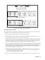
SAFETY SYMBOLS
Direct current
Alternating current
Both direct and alternating current
Three-phase alternating current
Earth (ground) terminal
Protective earth (ground) terminal
Frame or chassis terminal
Terminal is at earth potential. Used for measurement and control circuits designed to be operated with
one terminal at earth potential.
Terminal for Neutral conductor on permanently installed equipment
Terminal for Line conductor on permanently installed equipment
On (supply)
Off (supply)
Standby (supply). Units with this symbol are not completely disconnected from ac mains when this
switch is off. To completely disconnect the unit from ac mains, either disconnect the power cord or have
a qualified electrician install an external switch.
In position of a bi-stable push control
Out position of a bi-stable push control
Caution, risk of electric shock
Caution, hot surface
Caution (refer to accompanying documents)
4
WARNING
The WARNING sign denotes a hazard. It calls attention to a procedure, practice, or the like, which, if not
correctly performed or adhered to, could result in personal injury. Do not proceed beyond a WARNING
sign until the indicated conditions are fully understood and met.
Caution
The CAUTION sign denotes a hazard. It calls attention to an operating procedure, or the like, which, if
not correctly performed or adhered to, could result in damage to or destruction of part or all of the
product. Do not proceed beyond a CAUTION sign until the indicated conditions are fully understood and
met.
DECLARATION OF CONFORMITY
According to ISO/IEC Guide 22 and CEN/CENELEC EN 45014
Manufacturer’s Name and Address
Responsible Party
Agilent Technologies, Inc.
550 Clark Drive, Suite 101
Budd Lake, New Jersey 07828
USA
Alternate Manufacturing Site
Agilent Technologies (Malaysia) Sdn. Bhd
Malaysia Manufacturing
Bayan Lepas Free Industrial Zone, PH III
11900 Penang,
Malaysia
Declares under sole responsibility that the product as originally delivered
Product Names
a) 1 kW Single Output System dc Power Supplies
b) 1 kW Single Output dc Power Supplies
c) 200 W Single Output System dc Power Supplies
Model Numbers
a) 6030A; 6031A; 6032A; 6035A
b) 6010A; 6011A; 6012B; 6015A
c) 6033A 6038A
(and other customized products based upon the above)
Product Options
This declaration covers all options and customized products based on the above products.
Complies with the essential requirements of the Low Voltage Directive 73/23/EEC and the EMC
Directive 89/336/EEC (including 93/68/EEC) and carries the CE Marking accordingly .
EMC Information
ISM Group 1 Class A Emissions
As detailed in
Electromagnetic Compatibility (EMC), Certificate of Conformance Number
CC/TCF/00/078 based on Technical Construction File (TCF) HPNJ5, dated
Oct. 29, 1997
Assessed by:
Celestica Ltd, Appointed Competent Body
Westfields House, West Avenue
Kidsgrove, Stoke-on-Trent
Straffordshire, ST7 1TL
United Kingdom
Safety Information
and Conforms to the following safety standards.
IEC 61010-1:2001 / EN 61010-1:2001
UL 1244
CSA C22.2 No. 1010.1:1992
This DoC applies to above-listed products placed on the EU market after:
January 1, 2004
Date
Bill Darcy/ Regulations Manager
For further information, p lease contact your local Agilent Technologies sales office, agent or distributor, or
Agilent Technologies Deutschland GmbH, Herrenberger Straβe 130, D71034 Böblingen, Germany
Revision: B.00.00
Issue Date: Created on 11/24/2003 3:35
PM
Document No. 60xyA.11.24.doc
5
Acoustic Noise Statement
Herstellerbescheinigung
Diese Information steht im Zusammenhang mit den Anforderungen der
Maschinenlärminformationsverordnung vom 18 Januar 1991.
* Schalldruckpegel Lp < 70 dB(A) * Am Arbeitsplatz * Normaler Betrieb * Nach DIN 45635
T. 19 (Typprüfung)
Manufacturer’s Declaration
This statement is provided to comply with the requirements of the German Sound Emission
Directive, from 18 January 1991. This product has a sound pressure emission (at the operator
position) < 70 dB.
* Sound Pressure Lp < 70 dB(A) * At Operator Position * Normal Operation * According to
ISO 7779 (Type Test).
6
Table Of Contents
1.
General Information
Introduction .................................................................................................................................................... 9
Description ...................................................................................................................................................... 9
Safety Considerations ..................................................................................................................................... 9
Options ............................................................................................................................................................ 9
Accessories ................................................................................................................................................... 10
Instrument & Manual Identification .............................................................................................................. 11
Ordering Additional Manuals........................................................................................................................ 11
Related Documents ....................................................................................................................................... 11
Specifications ............................................................................................................................................... 11
2.
Installation
Introduction .................................................................................................................................................. 17
Initial Inspection............................................................................................................................................ 17
Mechanical Check ....................................................................................................................................... 17
Electrical Check .......................................................................................................................................... 17
Preparation for Use ....................................................................................................................................... 17
Location & Cooling..................................................................................................................................... 17
Outline Diagram.......................................................................................................................................... 18
Bench Operation.......................................................................................................................................... 18
Rack Mounting............................................................................................................................................ 18
Input Power Requirements .......................................................................................................................... 18
Power Connection ......................................................................................................................................... 19
Agilent Models 6010A, 6011A, 6012B, and 6015A ................................................................................... 19
Agilent Models 6023A, 6028A ................................................................................................................... 19
Line Voltage Option Conversion................................................................................................................... 20
Agilent Models 6010A, 6011A, 6012B, and 6015A ................................................................................... 20
Agilent Models 6023A, 6028A ................................................................................................................... 21
AC Line Impedance Check ........................................................................................................................... 23
Repackaging for Shipment ............................................................................................................................ 23
Rear Panel Screw Sizes and Part Numbers ................................................................................................... 24
3.
Operating Instructions
Introduction .................................................................................................................................................. 25
Turn-On Checkout Procedure ....................................................................................................................... 26
Initial Setup & Interconnections.................................................................................................................... 28
Connecting the Load ................................................................................................................................... 28
Overvoltage Protection................................................................................................................................ 30
Protective Shutdown ................................................................................................................................... 30
Operating Modes........................................................................................................................................... 31
Normal Mode .............................................................................................................................................. 31
Constant Voltage Operation ........................................................................................................................ 33
Constant Current Operation......................................................................................................................... 34
Remote Voltage Sensing ............................................................................................................................... 34
Analog Programing ....................................................................................................................................... 36
Constant Voltage Output, Resistance Control ............................................................................................. 36
Constant Voltage Output, Voltage Control ................................................................................................. 37
Constant Current Output, Resistance Control.............................................................................................. 38
Constant Current Output, Voltage Control.................................................................................................. 39
7
Multiple-Supply Operation............................................................................................................................ 39
Auto-Parallel Operation .............................................................................................................................. 39
Series Operation .......................................................................................................................................... 40
Monitor Signals............................................................................................................................................. 41
A
100 VAC Input Power Option 100
General Information ...................................................................................................................................... 43
Description ................................................................................................................................................. 43
Scope of Appendix A .................................................................................................................................. 43
Using Appendix A....................................................................................................................................... 43
Section 1 Manual Changes .......................................................................................................................... . 43
Section 2 Manual Changes .......................................................................................................................... . 43
Section 3 Manual Changes ............................................................................................................................ 44
Index
...................................................................................................................................................................... 45
8
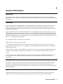
1
General Information
Introduction
This manual contains specifications, installation instructions, and operating instructions for DC Power Supply Models:
Agilent6010A, 6011A, 6012B, 6015A, 6023A and 6028A. Refer to "Related Documents" for other information concerning
these products.
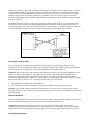
Description
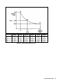
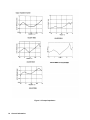
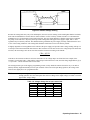
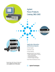
These power supplies are autoranging supplies. Autoranging allows the power supply to deliver full output power over a
higher voltage and current combination than would be possible with a rectangular output characteristic (see figure 1-1).
They use a 20k Hz pulse-width modulation circuit with power MOSFETs to provide the autoranging output characteristic
with laboratory performance.
Output voltage and current are continuously indicated on two 3 ½ digit displays. Front-panel controls allow the user to set
output voltage, current and Overvoltage Protection (OVP) trip levels. OVP protects the load by quickly and automatically
interrupting energy transfer if a preset voltage trip level is exceeded. Push button switches allow the display to alternately
show the programmed values of voltage and current or the overvoltage limit. LED indicators show the operating state of the
unit (CV, CC, Unregulated and Overvoltage).
All connections are made to rear-panel screw-on terminals.
Output voltage can be locally or remotely sensed.
A six-position MODE switch located on the rear panel is used to change from front panel control to remote voltage or
remote resistance control. See section 3 for a description of remote programming, remote sensing and several methods of
multiple supply operation.
Either the positive or negative output terminal may be grounded or the output may be floated (including output voltage) up
to ± 240 Vdc on models 6011A, 6012B, 6023A and 6028A or ± 550 Vdc on models 6010A and 6015A from chassis
ground.
The power supply is fan cooled and is packaged in an Agilent Technologies System II-compatible modular that provides
easy access for servicing. A thermostat shuts down the supply if an over-temperature condition occurs and resets
automatically.
Safety Considerations
This product is a Safety Class 1 instrument (provided with a protective earth terminal). The instrument and this manual
should be reviewed for safety markings and instructions before operation. Refer to the Safety Summary page at the
beginning of this manual for general safety information. Safety information for specific procedures is located at appropriate
places in this manual.
Options
Options are standard factory modifications or accessories that are delivered with the supply. The following options are
available. Note lower output power and voltage specifications for Option 100, which is described in Appendix A.
General Information
9
Option
100
120
220
240
800
908
909
0L2
0B3
Description
Input power: 100 Vac + 6%, -10%; 48-63 Hz single phase.
Input power: 120 Vac +6%, -13%. 48-63 Hz single phase.
Input Power: 220 Vac +6%, -13%; 48-63 Hz, single phase.
Input power: 240 Vac +6%, -13%; 48-63 Hz, single phase.
Rack mount kit for two units side by side (models 6023A and 6028A only)
Rack mounting kit
Flanges with Handles
One additional User’s Guide
Service Manual
Accessories
The System-II cabinet accessories listed below may be ordered with the power supply or separately from your local Agilent
Technologies Sales and Support Office (see list of addresses at rear of this manual).
For Agilent Models 6023A and 6028A
Agilent Part No Description
5062-3989
Front handle kit for 5-1/4 inch high cabinets
1460-1345
Tilt stand (1) snaps into standard foot on; must be used in pairs
5062-3977
Rack flange kit for 5-1/4 inch high cabinet (will be shipped with supply if ordered as Option 908)
5062-3983
Rack mount flange kit with handles
1494-0060
Rack slide kit, non tilting
5060-2865
Service kit, includes extenders for control and power mesh boards, three cables to allow GP-IB and
PSI boards to lie on table outside unit, and control board test connector.
5060-2866
FET service kit. Includes FETs and all components that should be replaced with FETs.
59510A
Relay Accessory
59511A
Relay Accessory (Polarity Reversing)
For Agilent Models 6023A and 6028A
For Agilent Models 6023A and 6028A
Agilent Part No Description
5062-3960
Rack mounting adapter kit for side mounting one 7-inch high cabinet, includes one rack flange and one
half-module width extension adapter. (Will be shipped with instrument if ordered as Option 908). This
rack mounting adapter kit is not compatible with front handle kit Agilent P/N 5061-3990).
5062-3961
Rack mounting adapter kit for center mounting one 7-inch high cabinet, includes one rack flange and
one quarter-module width extension adapter (two kits required), there will be surplus of hardware.
5062-3978
Rack flange kit for 7-inch high cabinet. Must be used with another half-module width unit of equal
depth with lock link kit 5061-9694. (Will be shipped if instrument is ordered as Option 800).
5061-9694
Lock link kit for joining units of equal depth, contains hardware for three side-by-side joints (four
units) and two over-under joints (three units). Locking cabinets together horizontally in a configuration
wider than one full module is not recommended. 5062-3978 and 5061-9694 will be shipped if Option
800 is ordered.
5062-3990
Front handle kit for 7-inch high cabinets. Corresponding flange kit is 5061-2072. This front handle kit
is not compatible with rack mounting adapter kit (Agilent PIN 5062-3960) or Option 908.
5061-2072
Flange kit to be used with front handle kit 5062-3990.
5062-3984
Rack mounting flange kit with handles for 7-inch high cabinet. Must be used with another half-module
width unit of equal depth with lock link kit 5061-9694.
5062-4003
Bail handle kit for carrying 7-inch high, half-module width cabinet.
1460-1345
Tilt stand (1) snaps into standard foot on instrument, must be used in pairs.
5062-3998
Support shelf bit for mounting on or more 7-inch high cabinets of any depth to 20 inches.
5062-4027
Front filler panel, half-module width, for 7-inch high cabinet on support shelf.
1494-0065
Slide kit for 5061-0098 support shelf.
06033-60005
Service kit, includes extenders for control and power mesh boards, three cables to allow GP-IB and
10
General Information
5060-0138
5060-2860
59510A
59511A
PSI boards to lie on table outside unit, and control board test connector.
GP-IB connector non-metric to metric conversion kit.
FET service kit, includes FETs and all components that should be replaced with FETs.
Relay Accessory
Relay Accessory (Polarity Reversing)
Instrument and Manual Identification
The serial numbers listed on the front of this guide indicate the versions of the supplies that were available when the manual
was issued. If changes have been made to the instrument since the publication of this manual the manual may include a
loose yellow "Manual Change’’ sheet. That sheet updates this manual by defining any differences between the version of
your supply and the instruments described in this manual, and may also include information for correcting any manual
errors. Note that because not all changes to the product require changes to the manual, there may be no update information
required for your version of the supply.
Ordering Additional Manuals
One User’s Guide is shipped with each power supply. Additional User’s Guides and Operating and Service manuals may be
purchased directly from your local Agilent Technologies Sales office. Specify the model number, serial number prefix, and
the manual part number provided on the title page. (When ordered at the same time as the power supply, additional manuals
may be purchased by adding Option 910 to the order. Each Option 910 includes one User’s Guide and one Operating and
Service Manual).
Related Documents
The following service documents can be ordered from your local Agilent Sales Office.
Agilent 6010A Operating and Service manual Agilent part number 06010-90001
Agilent 6011A Operating and Service manual Agilent part number 06011-90001
Agilent 6012B Operating and Service manual Agilent part number 06012-90004
Agilent 6015A Operating and Service manual Agilent part number 06015-90001
Agilent 6023A Operating and Service manual Agilent part number 06023-90001
Agilent 6028A Operating and Service manual Agilent part number 06010-90001
Specifications
Specifications for the power supply fall into two major categories: performance specifications and supplemental
characteristics.
Performance specifications describe the power supply's warranted performance. All performance specifications are at the
rear output terminals with a resistive load. Specifications apply over the full operating temperature range of 25 +/- 5°C
unless otherwise specified range. The Service Manual has procedures for verifying the performance specifications.
Supplemental characteristics give typical but non-warranted performance parameters. Design or type testing determines
supplemental characteristics. They are useful in understanding the power supply’s operation when accessing applications for
the power supply.
General Information
11
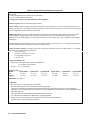
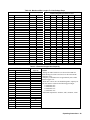
Table 1-1 Performance Specifications
Agilent Technologies Model
DC Output: Voltage, current and power spans indicate range
over which output may be varied using front panel controls.
6010A
6011A
0-200 V
0-17 A
1000-1200 W
0.01% + 5 mV
0-20 V
0-120 A
840-1072 W
0.01% + 3 mV
Current
0.01% + 10 mA
0.01% + 15 mA
Voltage
0.01% + 5 mV
0.01% + 2 mV
Current
Voltage
Current
Time 10%/50%
0.01% + 5 mA
22 mV/50 mV2
15 mA/1, 4
2 ms/3 ms
0.01% + 25 mA
8 mV/50 mV
120 mA/1,4
2 ms/3 ms
Level 10%/50%
150 mV/500mV
100 mV/300mV
Volts
Amps
Maximum Power
Voltage
Load Effect (Load Regulation) Voltage load effect is given for a load
current change equal to the current rating of the supply. Current load
effect is given for a load voltage change equal to the voltage rating of the
supply.
Source Effect (Line Regulation): Given for a change within the rated
line voltage for any output within the rated output voltage, current and
power of the supply
PARD (Ripple and Noise): Measured at any line voltage and under any
load condition within rating (rms 10 Hz to 10 Mhz/p-p 10 Hz to 20 MHz)
Load Effect Transient Recovery: Maximum time required for output
voltage to recover within the specified band around the nominal output
voltage following a step change (10% or 50%) in output current while
operating in the constant voltage mode
Table 1-2. Supplemental Characteristics
Agilent Technologies Model
Voltage Resolution
Current Resolution
Range
Resolution
Accuracy
Programming: Given for control of the
output over the GP-IB or with front panel controls
Front Panel Voltmeter:
T.C. (per/°C)
Range
Resolution
Accuracy
T.C. (per/°C)
Range
Resolution
Accuracy
T.C. (per/°C)
100 Vac (Opt.100)
120 Vac (Std.)
220 Vac (Opt.220)
240 Vac (Opt.240)
Front Panel Ammeter:
Display OVP:
Maximum AC Input Current: +6% -13% (48-63) Hz
Typical input power at rated output power: (see point P2 on Figure 1-1)
Temperature Coefficient: Output change per degree Celsius change
in ambient following 30 minute warm-up.
Drift (Stability): Change in output (dc to 20 Hz) over 8-hour internal
under constant line, load, and ambient following 30-minute warm-up
Programming Response Time: The maximum time required
to change from zero volts to full scale voltage or from full scale
Up
voltage to 2 volts (6 volts for Agilent 6028A and 5 volts for Agilent 6015A)
and settle within the specified band. Full load is defined as the
Down
resistance equal to Vp1/Ip1. Light load is as specified
Overvoltage Protection: Trip voltage adjustable via front
panel control using the Display OVP function
Monitoring Output Accuracy: 0 to 5 V signals from rear panel terminals that
indicate 0 to full scale output voltage and current. Output impedance = 10K Ω.
Remote Analog Programming Accuracy
Resistance (0 to 4K)
Voltage (0 to 5V)
Reverse Voltage Protection: Maximum continuous current caused by reverse
voltage impressed across the output terminals.
12
General Information
Voltage
Current
Voltage
Current
Settling
Band
Full Load
No Load
Full Load
Light Load
Range
Resolution
Accuracy
Voltage
Current
Voltage
Current
Voltage
Current
Ac power on
Ac power off
6010A
6011A
70 mV
7 mA
20 V, 200 V
100 mV, 1 V
0.65% + 3.5 counts,
0.65% + 3.5 counts
80 ppm + 1 mV,
80 ppm + 1 mV
20 A
10 mA
0.6% + 4 counts
100 ppm + 2 mA
2000 V
1V
2.5% + 1.1 V
200 ppm + 3 mV
24
24 A
15 A
14 A
1435 W
80 ppm + 15 mV
100 ppm + 4 mA
0.03 % + 17 mV
0.03% + 5 mA
300 mV
5 mV
40 mA
20 V, 200 V
10 mV, 100 mV
0.6% + 2 counts,
0.8% + 2 counts
80 ppm + 1mV,
100ppm + 1 mV
200 A
100 mA
0.7% + 300 mA4
100 ppm + 3 mA
200 V
100 mV
2.5% + 625 mV
150 ppm + 3 mV
24
24 A
15 A
14 A
1375 W
100 ppm + 2 mV
180 ppm + 15 mA
0.03% + 3 mV
0.1% + 25 mA
30 mV
300 ms (0.4Ω )
300 ms
500 ms (0.4Ω )
3.5 s (open Ω)
0-214 V
600 mV
0.3% + 1.25 V
0.3% + 60 mV
300 ms (40 Ω)
300 ms
600 ms
1.5 s (50 Ω)
0-22 V
100 mV
0.25% + 625 mV
0.25% + 2 mV
0.36% + 10 mA
0.3% + 35 mA
0.5% + 35 mV
1% + 800 mA3
0.25% + 35 mA
0.4% + 800 mA3
17 A
7A
0.5% + 215 mV
1% + 170 mA
0.3% + 215 mV
0.36% + 170 mA
50 A
20 A
6012B
6015A
6023A
6028A
NOTES.
0-60 V
0-50 A
1000-1200 W
0.01% + 5 mV
0-500 V
0-5 A
1000-1050 W
0.01% + 40 mV
0-20 V
0-30 A
200-242 W
0.01% + 2 mV
0-60 V
0-10 A
200-242 W
0.01% + 3 mV
0.01% + 10 mA
0.03% + 34 mA
0.01% + 9 mA
0 01% + 5 mA
0.01% + 3 mV
0.01% + 13 mV
0.01% + 1 mV
0.01% + 2 mV
0.01% + 10 mA
0.005% + 5 mV/40 mV5
25 mA/1, 4
2 ms/3 ms
0.03% + 17 mA
50 mV/160 mV
50 mA1, 4
5 ms/6
0 01% + 6 mA
3 mV/30 mV
30 mA/1, 4, 7
1 ms/2 ms
0 01% + 2 mA
3 mV/30 mV
5 mA/1, 4
1 ms/6
100 mV/300 mV
200 mV/6
50 mV/150 mV
75 mV/6
1. P-P PARD not specified
2. Initially, for each degree
below 20°C the ripple
increases 2.4 mV/°C.
After load is applied
for 15 minutes, the increase
becomes 1.4 mV/°C.
3. After a five-minute wait.
4. CC PARD is specified for
a 1.2 m (4 feet) length load
lead
5. P-P 75mV (20 Hz to
100MHz
6. 50% change not specified
7. Typical common mode current
1 mA RMS/40 mA P-P
6012B
6015A
6023A
6028A
20 mV
20 mA
20 V, 200 V
10 mV, 100 mV
0.65% + 3.5 counts,
0.65% + 3.5 counts
80 ppm + 1mV,
80 ppm + 1mV
200 A
100 mA
0.6% + 4 counts
100 ppm + 2 mA
200 V
100 mV
2.5% + 550mV
200 ppm + 3 mV
24
24 A
15 A
14 A
1450 W
80 ppm + 4 mV
100 ppm + 8 mA
0.03 % + 5 mV
0.03% + 10 mA
90 mV/200 mV
300 ms/120 ms (3.4 Ω)
300 ms/ 120 ms
2 s/400 ms (3.4 Ω)
3 s/ 35 s (100 Ω)
0-64 V
200 mV
0.25% + 550 mV
0.3% + 15 mV
0.36% + 20 mA
0.5% + 70 mV
1% + 500 mA
0.3% + 70 mV
0.36% + 500 mA
50 A
20 A
15 mV
2.5 mA
2000 V
1V
1% + 3.5 counts
100 ppm + 30 mV
5 mV
10 mA
20 V, 200 V
10 mV, 100 mV
0.6% + 20 mV, 0.6 +
200mV
75 ppm + 0.25 mV
15 mV
10 mA
20 V, 200 V
10 mV, 100 mV
0.6% + 20 mV, 0.6 +
200mV
75 ppm + 0.25 mV
20 A
10 mA
1% + 4 counts
100 ppm + 7.5 mA
2000 V
1V
3% + 1 count
100 ppm + 30 mV
24
24 A
15 A
14 A
1256 W
100 ppm + 30 mV
100 ppm + 7 mA
0.03% + 40 mV
0.03% + 17 mA
750 mV
350 ms (250 Ω)
250 ms
600 ms (250 Ω)
7 s (100 Ω)
0-535 V
1.5 V
0.3% + 1.25 V
1% + 150 mV
0.5% + 100 mA
1% + 600 mV
2% + 425 mA
0.8% + 600 mV
0.7% + 425 mA
5A
5A
200 A
100 mA
0.6% + 200 mA
100 ppm + 1.5 mA
200 V
100 mV
2.5% + 250mV
200 ppm + 1 mV
6.0 A
6.5 A
3.8 A
3.6 A
340 W
70 ppm + 0.6 mV
100 ppm + 2 mA
0.02 % + 1 mV
0.03% + 10 mA
5 mV
100 ms (2 Ω)
100 ms
200 ms (2 Ω)
500 ms (50 Ω)
0-23 V
100 mV
0.25% + 250 mV
0.25% + 2 mV
0.3% + 15 mA
0.5% + 12 mV
1% + 110 mA
0.25% + 12 mV
0.3% + 110 mA
30 A
15 A
200 A
100 mA
0.6% + 70 mA
100 ppm + 1.5 mA
200 V
100 mV
2.5% + 250 mV
200 ppm + 1 mV
6.0 A
6.5 A
3.8 A
3.6 A
325 W
70 ppm + 0.6 mV
100 ppm + 2 mA
0.02% + 2 mV
0.03% + 10 mA
15 mV
150 ms (2 Ω)
120 ms
150 ms (2 Ω)
750 ms (50 Ω)
0-67 V
100 mV
0.25% + 250 mV
0.25% + 2 mV
0.3% + 15 mA
0.5% + 36 mV
1% + 40 mA
0.25% + 36 mV
0.3% + 40 mA
10 A
5A
General Information
13
Table 1-2 Supplemental Characteristics (continued)
DC Floating Voltage: Either output terminal may be floated up to the following voltage (including the output voltage) from
earth ground:
± 240 Vdc on Models 6011A, 6012B, 6023A, and 6028A
± 550 Vdc on Models 6010A and 6015A
Exceeding these voltages can result in damage to the equipment.
Efficiency (typical): 80% on maximum output boundary
Remote Sensing: The power supply maintains specifications at the load with up to 0.5 Volt per load lead with sense wire
resistance less than 0.2 Ω per lead and sense lead length less than 5 metres. Operation with up to 2 volts per load lead is possible
with some degradation of the load effect specification.
Multiple Operations: Up to two similar units may be connected in series, parallel or auto-parallel, to provide increased
output capabilities. Mixing supplies with dissimilar output capabilities is not recommended because under certain
conditions, the lower output supply may be stressed beyond its maximum voltage and or current capabilities by the higher
output supply.
Reactive Loads: Stable with inductive loads up to 100 mH and capacitive loads up to 10 F. CC compensation that provides
up to 10 H (with increased settling times) is available on special order.
Voltage Overshoot (typical): The output voltage will overshoot its steady state value by less than 250 mV (1 V on Model
6015A) due to any of the following conditions:
1. Up programming
2. Crossover from CC to CV mode
3. A step change of up to 5A
4. AC power on
Temperature Rating (°C):
• Operating is 0-50 (Agilent 6010A/6011A/6012B/6015A)
0-55 (Agilent 6023A/6028A)
• Storage is - 40 + 75 (all models)
Weight kg. (Lbs.)
Model
Agilent 6010A
Net
15.9 (35)
Shipping
21.3 (47)
Agilent 6011A
16.8 (37)
22.3 (49)
Agilent6012B
15.9 (35)
21.4 (47)
Agilent 6015A
16.3 (36)
21.7 (48)
Agilent 6023A
8.6 (19)
10.5 (23)
Agilent 6028A
8.6 (19)
10.5 (23)
Dimensions: See Figure 2-1.
Certification:
The unit is designed to comply with these requirements:
• IEC 348-Safety Requirements for Electronic Measuring Apparatus.
• CSA Electrical Bulletin 556B-Electronic Instruments and Scientific Apparatus for Special Use and Applications.
• VDE 0871.6.78 Level B-RFI Suppression of Radio Frequency Equipment for Industrial, Scientific, and Medical (ISM)
and similar purposes.
• VDE 0411-Electronic Measuring Instruments and Automatic Controls.
• UL 1244-Electrical and Electronic Measuring & Testing Equipment.
• ANSI C39.5 Part 0 Draft 8-Electrical Testing, Measurement, and Control Equipment.
• Agilent Class B – Environmental Specifications
14
General Information
Model
Vp1
Ip1
Vp2
Ip2
Vp3
Ip3
Agilent
6010A
200 V
5A
120 V
10 A
60 V
17 A
Agilent
6011A
20 V
50 A
14 V
76 A
7V
120 A
Agilent
6012B
60 V
17.5 A
40 V
30 A
20 V
50 A
Agilent
6015A
500 V
2A
350 V
3A
200 V
5A
Agilent
6023A
20 V
10 A
14 V
17.2 A
6.7 V
30 A
Agilent
6028A
60 V
3.3 A
40 V
6A
20 V
10 A
Figure 1-1. Output Characteristic Curve
General Information
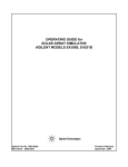
15
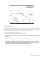
Figure 1-2. Output Impedance
16
General Information
2
Installation
Introduction
This section contains instructions for checking and repackaging the supply; bench or rack mounting, connecting the supply
to ac input power, and converting the supply from one line voltage to another if required..
Note:
All power supplies generate magnetic fields that may affect the operation of other instruments. If your
instrument is susceptible to operating magnetic fields, do not locate it in the immediate vicinity of the
power supply. Typically, at three inches from the supply, the electromagnetic field is less than 5 gauss.
Many CRT’s, such as those used in computer displays, are susceptible to magnetic fields much
lower than 5 gauss. Check susceptibility before mounting any display near the power supply.
Initial Inspection
Before shipment, this supply was inspected and found to be free of mechanical and electrical defects. As soon as the supply
is unpacked, inspect for any damage that may have occurred in transit. Save all packing materials until the inspection is
completed. If damage is found, file a claim with the carrier immediately. The Agilent Technologies Sales and Support office
should be notified as soon as possible.
Mechanical Check
This check should confirm that there are no broken knobs or connectors, that the cabinet and panel surfaces are free of dents
and scratches, and that the meter face and rear-panel plastic covers are not scratched or cracked.
Electrical Check
Section III contains an abbreviated check that can be used quickly to place the supply into operation. Refer to the inside
cover page of the manual for Certification and Warranty statements.
Preparation for Use
In order to be put into service, the power supply must be connected to an appropriate ac input power source. Also, the line
voltage for which the supply is set must be checked. Additional steps may include line voltage conversion and rack
mounting. Do not apply power to the supply before reading the “Input Power Requirements” section in this chapter.
Location and Cooling
The supply is fan cooled and must be installed with sufficient space in the rear and on sides for airflow. It should be used in
an area where the ambient temperature does not exceed + 50 °C (55 °C for models 6023Aand 6028A).
Caution:
When mounting several units in an enclosed rack, care should be taken to insure there is sufficient airflow
through the enclosure. Failure to provide sufficient airflow may result in damage to the power supply or
other equipment in the enclosure.
Installation
17
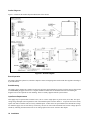
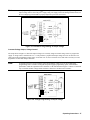
Outline Diagrams
Figure 2-1 illustrates the outline shape and dimensions of the cabinet.
6023A ONLY
6028A
ONLY
Figure 2-1. Outline Diagram
Bench Operation
The supply cabinet has plastic feet, which are shaped to ensure self-aligning when stacked with other Agilent Technologies
System II cabinets.
Rack Mounting
The supply can be mounted in a standard 19-inch rack enclosure. Rack mounting accessories for these units are listed in the
ACCESSORIES paragraph in Section I. Complete installation instructions are included with each rack mounting kit.
Support rails are also required for rack mounting. These are usually supplied with the system cabinet.
Input Power Requirements
This supply may be operated from a nominal 120 V, 220 V or 240 V single-phase ac power source (48-63 Hz). The input
voltage range and input current required for each of the nominal inputs is listed in Table 1-1. To operate from 100 Vac line,
Option 100 must be installed. This is a factory-installed option. A label on the rear panel indicates the nominal line voltage
for which the supply was set at the factory. If necessary, the user can convert the instrument from one line voltage option to
another by following the instructions in the “Line Voltage Option Conversion” section in this chapter.
18 Installation
Power Connection
Caution:
Connection of this supply to an ac power source should only be performed by an electrician or other
qualified person. Before connecting the supply to the ac power source, check the label on the rear panel to
ensure that the supply is set for the correct ac voltage to be used. If necessary, convert the line voltage to
another by following the instructions under “Line Voltage Conversion”.
Agilent Models 6010A, 6011A, 6012B and 6015A.
To connect input power, to the instrument proceed as follows:
a.
Remove the AC filter assembly cover by unscrewing the four locating screws.
b.
Insert the power cord through the strain relief clamp located on the cover.
c.
Connect the wires to the terminal block in accordance with the prevailing color codes.
Green or green/yellow to the terminal labeled " ''
White or blue wire to the terminal labeled "N'' *
Black or brown wire to the terminal labeled ''L"
* In a 2-phase system, such as 208 in the USA, the second phase is connected to the "N'' terminal.
WARNING: For proper protection by the instrument circuit breaker, the wire connected to the "L’’ terminal on
the instrument must be connected to the "L’’ side of the line (hot); the wire connected to the ’’N"
terminal must be connected to the "N" side of the line (neutral or common).
To protect operating personnel, the wire connected to the " ’’ terminal must be connected to
earth ground. In no event shall this instrument be operated without adequate ground connection.
d.
Replace the cover, tighten all four screws and tighten the strain relief clamp. (All four screws must be tightened for unit
to meet RFI specifications.)
e.
Connect the other end of the power cord to an appropriate power source.
Note:
Connections to the ac power line must be made in accordance with applicable electrical codes. The
international color code for identifying mains supply conductors is green/yellow, blue, and brown for
earth, neutral, and line respectively. Corresponding USA/Canadian codes are green, white, and black.
Caution:
Before applying power to the instrument, check to see that the rear-panel circuit breaker CB1 is on. The
breaker may trip due to rough handling during transit. If the breaker is found to be tripped at any
other
time for unknown reasons, refer to the troubleshooting procedures in the Service Manual.
Agilent Models 6023A and 6028A.
The power supply is shipped from the factory with a power-cord plug appropriate for the user’s location. Figure 2-2
illustrates the standard configuration of power-cord plugs used by Agilent Technologies. With each drawing is the Agilent
Part Number for a replacement power cord equipped with a plug of that configuration. If a different power cord is required,
contact the nearest Agilent Technologies Sales and Service office.
To protect operating personnel, the National Electrical Manufacturers Association (NEMA) recommends that the instrument
panel and cabinet be grounded. This supply is equipped with a three-conductor power cable; the third conductor is the
ground conductor. When the cable is plugged into an appropriate receptacle the supply is grounded. In no event shall this
supply be operated without an adequate cabinet ground connection.
Installation
19
The offset pin on the standard power cable three-prong connector is the ground connection. If a two-contact receptacle is
encountered, it must be replaced with a properly grounded three-contact receptacle in accordance with the National
Electrical Code and any local codes and ordinances. The work should be done by a qualified electrician only.
Note:
To reduce noise pickup, it is good practice to keep the ac input lines separated from signal lines.
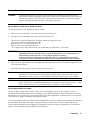
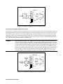
Line Voltage Option Conversion
Caution:
Conversion to or from 100 V operation requires replacement of internal components and calibration in
addition to the line voltage components, and is to be done only at the factory. Failure to configure and
calibrate the power supply properly may result in damage to the unit.
Agilent Models 6010A, 6011A, 6012B and 6015A.
Line voltage conversion is accomplished by adjusting three components: a two-section line select switch, and a line-voltage
jumper. To convert the supply from one line voltage option to another, proceed as follows:
WARNING: Some components and circuits are at ac line voltage even with the LINE switch off. To avoid
electric shock hazard, disconnect line cord and load, and wait two minutes before removing covers.
a.
Remove the outside cover by removing the four screws that hold the carrying straps, spread the bottom of the cover
slightly and carefully slide the cover to the rear of the supply until it is clear. Next remove the top inside cover by
removing the nine screws, four on top, three on right side, and two on left side, which connect the top inside cover to
the supply chassis.
b.
Remove the FET board to reach the line-voltage jumper (W1) terminals.
c.
Use a small-blade screwdriver to set the two switch sections of S2 to match the pattern printed on the main board for
the nominal line voltage to be used. For example, to set switches for 120 V operation, move forward switch section so
that its white slot is toward front of supply and move rearward switch section so that its white slot is toward rear of the
instrument.
d.
Set switch S1 to match the rearward section of S2, i.e., toward the rear for 100/120 V operation, toward the front for
220/240 V operation.
e.
One end of W1 is soldered to the main board; the other end has a female quick-connect terminal that fits onto one of
two terminals soldered to the main board. For 100 V or 120 V operation, W1 must be connected to terminal J9; for 220
V or 240 V operation, W1 must be connected to terminal J10. Be certain that the jumper is firmly mated with the
connector on the main board. Do not grip jumper insulation with pliers; either grip the jumper wire by hand or grip the
jumper terminal with pliers.
f.
Replace FET board, inside top cover and outside top cover. Mark the unit clearly with a tag or label indicating correct
line voltage to be used.
g.
Change line label.
20 Installation
#8 Ring
Terminals
Option 831, 8120-5573, 12 AWG unterminated
Option 833, 8120-5568, 1.5 mm2 unterminated
Option 834, 8120-5566, 10 AWG unterminated
Option 841
8120-5572
Option 843
8120-5571
Option 845
8120-5570
Option 846
8120-5565
Option 847
8120-5567
Option 848
8120-5569
Agilent 6010A, 6011A, 6012B,
Option 900
8120-1358
Option 901
8120-1369
Option 902
8120-1689
Option 903
8120-1348
standard
Option 904
2151-3498
plug only
Option 906
8120-2104
HP 6023A, 6028A
Figure 2-2. Power-Cord Plug Configurations
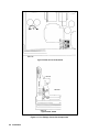
Agilent Models 6023A and 6028A.
Line voltage conversion is accomplished via three components; a two-section line select switch, line voltage jumper, and a
rear panel fuse. To convert the supply from one voltage to another, proceed as follows:
a.
Unplug the power supply and wait 2 minutes for internal capacitors to discharge.
b.
Remove the outside cover by removing the rear screw that holds the carrying strap, then carefully slide the cover to the
rear of the supply until it is clear. Do not remove the front carrying strap screw.
c.
The line voltage select switch (S2) is located in the front left corner of the supply (see Figure 2-3). Use a small-blade
screwdriver to set the two switch sections to match the pattern silk-screened on p.c. main board as shown in Figure 2-3.
For example, to set switches for 120 V operation (as illustrated), move forward switch section so that its white slot is
toward front of supply and move rearward switch section so its white slot is toward rear of supply.
d.
One end of W5 is soldered to motherboard; the other end has a female right-angle quick-connect terminal that fits onto
one of two terminals soldered to motherboard. For 100 V or 120 V operation, W5 must be connected to terminal closer
to center of supply; for 220 V or 240 V operation, W5 must be connected to terminal closer to side of supply. Be
certain that jumper is firmly mated with terminal on motherboard. Do not grip jumper insulation with pliers; either grip
jumper wire by hand or grip jumper terminal with pliers.
e.
Check rating of fuse installed in rear-panel fuseholder. It should be 8 A for 100 or 120 Vac line voltages, or 4 A for
220 or 240 Vac line voltages. If necessary, replace the fuse with one of correct value. Do not use time-delay fuses.
8 AM, 250 Volt fuse; Agilent part number 2110-0383
4 AM, 250 Volt fuse; Agilent part number 2110-0055
f.
Replace covers and clearly mark the supply with a tag or label indicating the correct line voltage and fuse to be used.
Installation
21
Agilent 6010A, 6011A, 6012B, 6015A
Agilent 6023A, 6028A
Figure 2-3. Line Voltage Conversion Components
22 Installation
AC Line Impedance Check
The power supply is designed for proper operation with line impedances typically found in ac power lines. However, if the
supply is connected to an ac power line having a high impedance combined with line voltage near the minimum specified
value, (e.g., 104 Vac for nominal 120 Vac), the unit will go out of regulation if it is asked to provide full rated output power.
Such a situation might occur if the supply is connected to ac power an extended distance from the main ac distribution
terminals and/or if the ac power wires from the main ac distribution terminals are of relatively small gauge.
Measurement of ac line voltage at the supply input terminals typically is not a reliable indication of the actual ac line voltage
because of the peak clipping effect of the power supply and the averaging effect of the voltmeter. Symptoms of excessive
line impedance may include erratic or no output from the supply and/or inability of the supply to provide full output power.
If there is reason to suspect the ac power lines to the supply may have high impedance, perform the following check:
WARNING: This check should be performed only by service-trained personnel who are aware of the hazards
involved (for example, fire and electrical shock). Turn the power supply off before making or
breaking any connections to the power supply. Hazardous voltages are present within the unit even
when the power switch is turned off.
a.
Connect a variable load to the supply. Using the OUTPUT ADJUST controls and DISPLAY SETTINGS, set voltage
and current (see Section III for detailed description) to maximum rating.
b.
Set the load to the maximum rated output current for the power supply (see Appendix A, Figure A-1). The power
supply output voltage should be greater than:
Model
Agilent 6010A
Agilent 6011A
Agilent 6612B
Agilent 6015A
Agilent 6023A
Agilent 6028A
c.
Voltage
65V
8V
22V
220V
6V
20V
If the supply voltage is less than specified, perform the power limit calibration given in the Service Manual. If the
power limit is calibrated correctly, but the unit still does not provide the required output, then the power supply is not
receiving adequate ac line input.
Repackaging for Shipment
To insure safe shipment of the instrument, it is recommended that the package designed for the instrument be used. The
original packaging material is reusable. If it is not available, contact your local Agilent Technologies Sales and Support
office to obtain the materials. This office will also furnish the address of the nearest service office to which the instrument
can be shipped. Be sure to attach a tag to the instrument specifying the owner, model number, full serial number, and service
required or a brief description of the trouble.
Installation
23
Rear Panel Screw Sizes and Part Numbers
Refer to the following list if you need to replace any of the rear panel connection hardware:
Agilent Models 6010A, 6011A, 6012B and 6015A
Item
Description
ac input cover
ac input cover screws
M4 X 0.7 X 60 mm (qty 4)
ac input barrier block
3-terminal barrier block
ac input barrier block screws
8-32 X 5/16 (qty 3)
dc output cover
dc output cover screws
M4 X 0.7 X 10 mm (qty 3)
control signal barrier block
6 - terminal barrier block
sense barrier block
2 - terminal barrier block
barrier block screws
M3.5 X 0.6 X 6 mm (qty 8)
output bus bar screws
M5 X 0.8 X 12 mm (qty 4)
output bus bar sense screws
M2 X 0.4 X 8 mm (qty 2)
red/black sense wires
wire kit
Agilent Part number
5060-3237
0515-0156
0360-2217
included with ac input barrier block
5040-1626
0515-0414
0360-2195
0360-2192
included with dc barrier blocks
0515-0155
0515-0212
5060-2913
Agilent Model 6023A and 6033A
Item
barrier block cover
control signal barrier block
sense barrier block
barrier block screws
dc output cover
dc output cover screws
output buss bar screws (large)
output buss bar screws (small)
sense jumpers
Agilent Part number
06023-00009
0360-2195
0360-2192
included with dc barrier blocks
0360-2191
0515-1085
0515-0885
0515-0886
0360-2190
24 Installation
Description
6 - terminal barrier block
2 - terminal barrier block
M3.5 X 0.6 X 6 mm (qty 8)
M4 X 0.7 X 8 mm (qty 2)
M4 X 0.7 X 8 mm (qty 2)
M3 X 0.5 X 6 mm (qty 2)
3
Operating Instructions
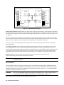
Introduction
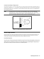
This section describes the operating controls and indicators, turn-on checkout procedures, and operating procedures and
considerations for the power supply. Front-panel operation and remote resistance/voltage programming is described in this
section. The front-panel controls and indicators are shown in Figure 3-1 and described in Table 3-1. Table 3-1 also lists the
pages, in which, use of the controls and indicators is described.
More theoretical descriptions regarding the operational features of power supplies in general are given in the Operating and
Service manual for your specific model and in the DC Power Supply Handbook, Application Note 90B (Agilent part
number 5952-4020).
6
5
7
$'&32:(56833/<9$:
287387$'-867
92/76
293
$036
92/7$*(&855(17
',63/$<
$'-867
6(77,1*6
',63/$<
293
&9&&815(*8/$7('2927
/,1(
2
21
OFF
1
9
10
11
13
12
8
3
2
4
$$%$
9
5
10
6
$'&32:(56833/<9$:
92/76
7
',63/$<
',63/$<
6(77,1*6
293
$036
&9&&815(*8/$7('29
12
11
8
/,1(
21
287387$'-867
293
92/7$*(&855(17
$'-867
2
1
2
3
4
$$
Figure 3-1. Front-Panel Controls and Indicators
Operating Instructions 25
Number
Controls/Indicators
1
LINE Switch
2
3
4
VOLTAGE CONTROL
CURRENT CONTROL
OVP ADJUST
5
Voltage Display
6
Current Display
7
DISPLAYS SETTINGS
Pushbutton Switch
8
DISPLAY OVP
Pushbutton Switch
9
CV Status Indicator
10
CC Status Indicator
11
UNREGULATED Status
Indicator
12
OVERVOLTAGE Status
Indicator
13
OVERTEMPERATURE
Status Indicator
Table 3-1. Controls and Indicators
Description
Pressing at the top of the switch applies ac mains voltage to the units
bias and power circuits. Unit is operational approximately 3 seconds
after power on.
Clockwise rotation increases the output voltage, 0 to full scale Vdc.
Clockwise rotation increases the output current, 0 to full scale Adc.
The recessed, single-turn screwdriver control sets the overvoltage
protection trip voltage
A 3-1/2-digit display with automatically positioned decimal point
that can indicate output voltage, output voltage setting or
overvoltage shutdown setting. During an error condition, the output
may exceed the display range and the display will indicate + OL.
A 3-1/2 digit display with automatically positioned decimal point
that can indicate output current or output current setting. During an
error condition, the output may exceed the display range, and the
display will indicate + OL.
Causes numeric displays to indicate programmed voltage and current
values, rather than actual output values; allows both settings to be
made without the necessity of opening or shorting load.
Causes VOLTS display to indicate OVP trip voltage, AMPS display
is blanked; allows setting to be made without changing output
settings or load connections
CV (Constant Voltage) indicates that the power supply is regulating
its output at a constant voltage.
CC (Constant Current) indicates that the power supply is regulating
its output at a constant current.
UNR (Unregulated) indicates that the power supply is operating
beyond its maximum output power specification and that the output
is not regulated or has been shutdown by a protective circuit.
OV (Overvoltage) indicates that the power supply output has been
shut down and latched by the occurrence of an overvoltage
condition. Removing the cause of the overvoltage and turning the
supply off and back on will reset the unit.
OT (Over temperature) indicates an overheating condition on either
the diode or FET boards. OT automatically resets when the
temperature drops to a safe operating level.
Page
27
27
27
30
27
27
33, 34
33, 34
33
34
31, 32
31
31
Turn-On Checkout Procedure
WARNING:
Before the instrument is turned on, all protective earth terminals, extension cords, and devices
connected to the power supply should be connected to a protective earth ground. Any
interruption of the protective earth grounding will cause a potential shock hazard that could
result in personal injury.
Caution:
This instrument can be damaged by electrostatic discharge into the control connectors, or the switches
on the rear panel even while the unit is turned on. Do not cause an electrostatic discharge into these
connectors and switches (which may occur when they are touched). Also, consistent with good
engineering practice, leads attached to customer accessible signal/monitoring ports should be twisted
and shielded to maintain the instruments specified performance.
The following procedure ensures that the supply is operational, and may be used as an incoming inspection check.
26 Operating Instructions
a.
Check that the rear-panel mode switches are set as shown in Figure 3-3.
b.
Check that + lead is connected to +S and the – lead is connected to –S and tightened securely. The + Sense lead is
connected to + Output and the − sense lead is connected to − Output lead at the factory.
c.
Check that the rear panel label indicates that the unit is set for the mains input voltage to be used. If not, refer to “Line
Voltage Conversion” in chapter 2.
d.
Plug the unit into the appropriate ac power outlet.
e.
Turn the Voltage control all the way down (fully counter clockwise) and the Current control up slightly clockwise to
ensure CV operation.
f.
Check that the recessed OVP ADJUST control on the front panel is fully clockwise.
g.
Press the top of the LINE rocker switch in to turn the power supply on. You should hear the fan. Check that the CV
indicator remains on.
h.
The VOLTS and AMPS displays should indicate approximately 0.00.
i.
Press the momentary-contact DISPLAY OVP pushbutton switch and check that VOLTS display indicates maximum
OVP for the power supply.
j.
Press the DISPLAY SETTINGS switch, Turn the CURRENT knob clockwise, and check that the AMP setting
increases. The CV indicator should be on and the CC indicator should be off.
k.
Turn the VOLTAGE control clockwise and check that the output voltage increases from zero to full output voltage as
indicated on VOLTS display. Continued clockwise rotation may cause VOLTS display to indicate + OL.
l.
Check the overvoltage protection circuit by turning OVP ADJUST control counterclockwise until OVP circuit trips.
Output should drop to 0 V, CV indicator turns off and OV indicator turn on .
m. Reset the OVP circuits by turning OVP ADJUST control fully clockwise and turning unit off and back on.
n.
To check the constant current circuit, turn the power supply off and short rear panel + and - output terminals with a wire
of sufficient gauge to carry the supply's maximum current output (see Table 3-3).
o.
Turn the power supply on and adjust the CURRENT control clockwise. Check that the output current increases from
zero to full output current as indicated on AMPS display. Continued clockwise rotation may cause AMPS display to
indicate + OL. The CC indicator should be on and CV indicator should be off.
p.
Turn off the power supply, remove the short from the output, and read following instructions before connecting load to
supply.
Operating Instructions 27
Initial Setup and Interconnections
WARNING:
Turn off input ac power before changing any rear-panel connection and make certain all wires
and straps are properly connected and terminal block screws are securely tightened before
reapplying power. Be certain to replace both terminal block covers before reapplying power to
avoid exposing the operator to hazardous voltages.
Connecting the Load
Load connections to the power supply are made at the + and – output terminals on the rear panel. Higher power units have
output bus bars. The bus bars are covered by an impact-resistant plastic cover, which is secured to the unit with four M4 x 8
screws. Be certain to replace the cover after making connections. Two factors must be considered when selecting wire size
for load connections, conductor temperature and voltage drop.
To satisfy safety requirements, the wires to the load should be at least heavy enough not to overheat while carrying the
maximum power supply output current that would flow if the load were shorted. Use Tables 3-2 and 3-3 to determine the
proper wire gauge for load connections to the power supply. When 2 or more wires are bundled together, the current
carrying capacity of each wire is reduced (see Table 3-3, Note 3). All wires must be properly terminated with connectors
securely attached. Do not connect unterminated wires to the power supply. Wire sizes of AWG #14 (2,5mm2) or smaller are
normally used only for sense leads.
The minimum wire size required to prevent overheating will not usually be large enough to provide good voltage regulation
at the load. For proper regulation the load wires should be large enough to limit the voltage drop to no more than 0.5 volts
per lead. Table 3-2 lists resistivity for various wire sizes and the maximum lengths that may be used to limit voltage drop to
0.5 volts for various currents. Lengths listed are the sum of the lengths of the (+ ) and ( - ) load wires. Lengths are given in
meters and (feet).
To determine maximum lengths (in meters or feet) for currents not listed, use the formula:
maximum length =
0.5 x 1000
current x resistance
where current is expressed in amps and resistance is expressed in ohms/km or ohms/1000 feet. If load regulation is critical,
use remote voltage sensing .
WARNING:
While calculating load wire size, remember that the wire must be large enough not to overheat
while carrying the current that would flow if the load were shorted.
Table 3-3 lists the maximum current-carrying capacity (ampacity) for various sizes of stranded copper wire.
If multiple loads are connected to one supply, each load should be connected to the supply's output terminals using separate
pairs of connecting wires. This minimizes mutual coupling effects and takes full advantage of the supply's low output
impedance. Each pair of connecting wires should be as short as possible and twisted or shielded to reduce noise pickup and
radiation.
If load considerations require the use of output distribution terminals that are located remotely from the supply, then the
power supply output terminals should be connected to the remote distribution terminals by a pair of twisted or shielded
wires. Each load should be separately connected to the remote distribution terminals. Remote voltage sensing is suggested
under these circumstances. Sense either at the remote distribution terminals, or (if one load is more sensitive than the
others) directly at the most critical load.
28 Operating Instructions
Table 3-2. Maximum Wire Lengths To Limit Voltage Drops
Resistivity
Maximum Length In Meters (Feet)To
Limit Voltage Drop To 0.5V Or Less
AWG
Cross-section (mm2)
5A
10A
17 A
30A
50A
Ω/kft
Ω/km
22
16.15
(6.19)
*
*
*
*
0,5
40.1
2.5
*
*
*
*
20
10.16
(9.8)
*
*
*
*
0,75
26.7
3.7
1.8
*
*
*
18
6.388
(15.6)
(7.8)
*
*
*
1
20,0
5.0
2.5
*
*
*
16
4.018
(24.8)
(12.4)
(7.3)
*
*
1,5
13.7
7.3
3.64
*
*
*
14
2.526
(40)
(19.7)
(11.6)
(6.6)
*
2,5
8.21
12.2
6.1
3.5
*
*
12
1.589
(62.9)
13.46)
(18.5)
(10.49) *
4
5.09
19.6
9.8
5.7
3.27
*
10
.9994
(100)
(50)
(29.4)
(16.68) (10.01)
6
3.39
29.5
14,7
8.6
5.9
*
8
0.6285
(160)
(79.5)
(46.7)
(26.52) (15.91)
10
1.95
51,2
25,6
15
8.55
5.13
6
0.3953
(252)
(126.5) (74.4)
(42.16) (25.3)
16
1.24
80.6
40,3
23.7
13.44
8.06
4
0.2486
(402)
(201)
(118)
(67.04) (40.23)
25
0.795
125.7
62.8
37
20.96
12.58
2
0.1564
(639)
(319)
(188)
(106.5) (63.94)
35
0.565
176.9
88.5
52
29.5
17.7
50
0.393
254.4
127
74.8
42.4
25.45
0
0.09832
(1017)
(508)
(299)
(169.5) (101.7)
* Wire not rated for power supply maximum current rating.
Wire Size
120A
*
*
*
*
*
*
*
*
*
*
*
*
*
*
*
*
*
*
(16.76)
5.24
(26.64)
7.37
10.6
(42.38)
Table 3-3. Stranded Copper Wire Ampacity
AWG
22
20
Wire Size
Cross Section (mm2)
0.75
1
18
1.5
16
2.5
14
4
12
6
10
10
8
6
4
2
0
Ampacity
5.0
8.33
10
13.5
15.4
16
19.4
25
31.2
32
40
40
55
63
75
100
135
180
245
NOTES:
1. Ratings for AWG-sized wires are derived from MIL-W5088B. Ratings for metric-sized wires are derived from IEC
Publication 335-1.
2. Ampacity of aluminum wire is approximately 84% of that
listed for copper wire.
3. When two or more wires are bundled together, ampacity for
each wire must be reduced to the following percentages:
2 conductors 94%
3 conductors 89%
4 conductors 83%
5 conductors 76%
4. Maximum temperatures: Ambient, 50°C; conductor, 105°C
Operating Instructions 29
Either positive or negative voltages can be obtained from the supply by grounding one of the output terminals. It is best to
avoid grounding the output at any point other than the power supply output terminals to avoid noise problems caused by
common-mode current flowing through the load leads to ground. Always use two wires to connect the load to the supply
regardless of where or how the system is grounded. Never ground the system at more than one point. The maximum
potential (including output voltage) that either output terminal is from ground must not exceed that specified on the output
label on the rear chassis.
The PARD specifications in Table 1-1 apply at the power supply output terminals. However, noise spikes induced in the
load leads at or near the load may affect the load although the spikes are inductively isolated from the power supply. To
minimize voltage spikes at the load, connect a bypass capacitor as shown in Figure 3-2. With this setup, peak-to-peak noise
at the load can actually be reduced to a level below the value specified at the power supply output terminals.
500
Figure 3-2. Connecting a Bypass Capacitor
Overvoltage Protection (OVP)
The overvoltage trip point is adjusted at the front panel. The approximate trip voltage range is from zero volts to
approximately 107% of maximum rated voltage of the power supply. When the OVP circuit trips, the power supply output
is disabled and delivers no output power, and the OVP and UNREGULATED indicators turn on.
Adjustment. OVP is set by the recessed single-turn OVP ADJUST potentiometer on the front panel. Rotating the control
clockwise sets the trip voltage higher. (It is set to maximum at the factory.) When adjusting the OVP trip point, the
possibility of false tripping must be considered. If the trip voltage is set too close to the supply’s operating voltage, a
transient in the output would falsely trip the OVP. For this reason it is recommended that the OVP trip voltage be set higher
than the output voltage by at least 1 volt. To adjust the OVP trip voltage, proceed as follows:
a.
b.
Turn on supply and hold DISPLAY OVP pushbutton in.
Insert a small-blade screwdriver through hole in front panel and adjust OVP trip voltage to desired level.
OVP Reset. To reset OVP, turn the LINE switch off and then back on. The cause of the overvoltage must be removed
before the OVP circuit is reset or the circuit will trip again immediately. If the OVP circuit trips continuously check the load
and the trip voltage.
Protective Shutdown
Protective circuits within the power supply may limit or turn off the output in case of abnormal conditions. The cause of the
protective action can be determined by observing the front panel indicators (lights and meters).
Unregulated. If an overrange condition exists (load tries to draw more power than the supply can deliver), the
UNREGULATED indicator turns on and both the CV and CC indicators are off. The product of the VOLTS and AMPS
displays will exceed the maximum output power of the supply. Also, if the power supply output is disabled by protective
30 Operating Instructions
circuits within the supply the power supply output drops to zero and the UNREGULATED indicator turns on. The power
supply can be disabled by overvoltage, overtemperature, or by low or high ac line (mains) voltage.
Overvoltage. If the voltage across the power supply output terminals rises above a preset level, possibly because of a
hardware malfunction, the overvoltage protection (OVP) circuit will trip. If this occurs, the power supply will be disabled
and the OV indicator turned on. To reset the OVP circuit, first ensure that the condition that caused the overvoltage is
corrected, then turn the power supply off and back on.
Overtemperature. If the overtemperature protection circuit trips, the power supply will be disabled and the OT indicator
turned on. The overtemperature circuit will reset automatically and the power supply output will be restored when the
temperature drops sufficiently for safe operation.
AC Line Over/Under Voltage. If the ac line (mains) input voltage increases or decreases beyond the range for safe
operation the power supply output may be disabled. The power supply output will be restored when the input voltage
returns within range.
Operating Modes
Settings or the rear panel Mode switch determines the operating mode of the unit. In Normal operating mode the unit is set
for local sensing, (where the output voltage is sensed directly at the output terminals) and front panel voltage and current
programming. Other operating modes covered in this chapter include remote voltage sensing, remote programming of
voltage and current using either external resistors or voltage sources, and multiple supply operation such as auto parallel and
auto series.
Figure 3-3 shows six switches on the rear panel that configure the power supply programming (either front-panel controls)
or remote analog programming (resistance or voltage). When shipped from the factory the switches are set for front-panel
programming, which is the normal operating mode for this power supply. The two analog programming modes are available
for use in special circumstances.
Typically, only one programming mode is used for both output parameters (voltage and current). However, the mode
switches allow voltage and current to be programmed independently. For example, voltage could be programmed from the
front panel, while current is resistance programmed. Note that only one programming mode can be used for each parameter
at one time.
Normal Mode
The unit is shipped from the factory configured in the normal operating mode – with the + and – outputs jumpered to the +
and sense connectors. The mode switch is set as shown in the following figure.
Figure 3-3. Factory Settings, Mode Switch
B6
B5
B4
B3
B2
B1
0
0
1
1
Handle
The power supply can operate as a constant voltage (CV) or constant current (CC) source over a wide range of output
voltage and current combinations. The specifications table contains a graph showing the overall output range of the power
supply. Figure 3-4 shows a rectangular operating locus that is defined by voltage and current settings of the power supply.
The load resistance determines the point on that locus at which the power supply actually operates. Three load-resistance
lines are shown on Figure 3-4. The line representing load resistance A, the highest load resistance shown on the graph,
Operating Instructions 31
crosses the operating locus at point 1. Point 1 is on the part of the operating locus defined by the voltage setting, so the
power supply operates in CV mode.
Similarly, the line representing load resistance C, the lowest load resistance shown on the graph, crosses the operating locus
at point 3. Point 3 is on the part of the operating locus defined by the current setting, so the power supply operates in CC
mode.
Load Resistance B equals the crossover resistance for the particular combination of voltage and current settings shown on
the graph. Either the CV or CC LED will light. If the load resistance increases, the voltage setting decreases, or the current
setting increases, the power supply will operate in CV mode. Conversely, if the load resistance decreases, voltage setting
increases, or current setting decreases, the power supply will operate in CC mode.
Figure 3-4. Determining Operating Point
In Figure 3-5, the voltage and current settings are high enough that the rectangular operating locus is cut off by the
maximum output power boundary of the power supply. For the load resistance A, the power supply operates in CV mode at
the voltage and current values for point 1. Similarly, for load resistance D the power supply operates in CC mode at point 4.
For load resistance between B and C, the operating point will be on the maximum output-power boundary between points 2
and 3, and the UNREGULATED indicator will be on. The VOLTS and AMPS displays will indicate the voltage and current
being supplied to the output. (The product of the two readings will exceed rated output power of the supply.) Note that the
actual boundary is beyond the specified minimum boundary. The UNREGULATED indicator will light only if the actual
boundary is exceeded.
The supply can operate in the overrange region for sustained periods without being damaged. However, the supply is not
guaranteed to meet specifications in overrange. Output ripple increases substantially and regulation is seriously degraded.
Note:
Under certain conditions of line and load, it is possible for the supply to provide more than rated output
power and still maintain regulation. If this occurs, the unit will operate normally and the OVERRANGE
indicator will be off. However, the slightest change in either line or load may cause the unit to go out of
regulation. Operation of the unit beyond the rated-output-power boundary is not recommended.
32 Operating Instructions
Figure 3-5. Overrange Operation
Constant Voltage Operation
By pressing the DISPLAY SETTINGS pushbutton switch you can observe the setting (limits) of both the output voltage and
the output current, rather than the actual output values. This you set the current limit when the power supply is operating in
CV mode, or set the voltage limit while in CC mode, without having to disconnect or adjust the load.
To set up the power supply for constant voltage operation:
a.
With power supply turned off, connect the load to the output terminals.
b.
Turn on power supply. Hold in DISPLAY OVP pushbutton switch and set OVP ADJUST potentiometer for the desired
OVP trip voltage.
c.
Hold DISPLAY SETTINGS pushbutton switch in and rotate CURRENT control to set desired current limit.
d.
Adjust output voltage to desired level. The CV indicator should be on.
e.
If a load change causes the current limit to be exceeded, the power supply automatically crosses over to constant
current operation (CC indicator will come on) and the output voltage drops proportionately. In setting the current limit,
make adequate allowance for high current peaks that could cause unwanted mode crossover.
Operating Instructions 33
Constant Current Operation
To set up the power supply for constant current operation:
a.
With power supply turned off, connect the load to the output terminals.
b.
Turn on the power supply. Hold in DISPLAY OVP pushbutton switch and set OVP ADJUST potentiometer for the
desired OVP trip voltage. In CC mode the voltage setting will limit output voltage under quiescent conditions, and the
OVP circuit provides added protection against hardware faults.
c.
Hold the DISPLAY SETTINGS pushbutton switch in, and rotate the VOLTAGE control to set desired voltage limit.
d.
Adjust the output current to the desired level. The CC indicator should be on.
e.
If a load change causes the voltage limit to be exceeded, the power supply automatically crosses over to constant
voltage operation and the output current drops proportionately. In setting the voltage limit, make adequate allowance
for voltage peaks that could cause unwanted mode crossover.
Remote Voltage Sensing
The remote sensing connections shown in Figure 3-6 improve the voltage regulation at the load by monitoring the voltage
there instead of at the supply’s output terminals. Remote sensing allows the power supply to automatically increase the
output voltage and compensate for the voltage drops in the load leads. This improves the voltage regulation at the load, and
is especially useful for CV operation with loads that vary and have significant load-lead resistance. Note that with remote
sensing, the internal voltmeter is connected at the load. Remote sensing has no effect during CC operation. When using
remote sensing, turn off the power supply before changing the rear-panel straps, sense leads, or load leads. Connect the unit
for remote voltage sensing by connecting load leads from + OUT and - OUT terminals to the load, disconnecting straps
between + Out and + S and between - Out and - S, and connecting sense leads from the + S and - S terminals to the load as
shown in Figure 3-6.
Note:
Sensing is independent of other power supply functions; either local or remote sensing can be used
regardless of how the power supply is programmed.
The load leads should be of the heaviest practical wire gauge, at least heavy enough to limit the voltage drop in each load
lead to 0.5 volts. The power supply has been designed to minimize the effects of long load-lead inductance, but best results
will be obtained by using the shortest load leads practical.
Note:
The OV circuit senses the voltage at + Out and at the output side of the internal current sampling resistor
in the – output lead. Remote voltage sensing compensates for a voltage drop of up to 0.5 V in each load
lead, and there may be up to 0.12 V drop between the – output and the internal sensing resistor at the
point the OVP circuit is connected. Therefore, the voltage sensed by the OVP circuit could be as much as
1.12 V more than the voltage being regulated at the load. It may be necessary to readjust the OVP trip
voltage to compensate for these drops when remote sensing.
34 Operating Instructions
Figure 3-6. Remote Voltage Sensing
Because the sensing leads carry only a few milliamperes, the wires used for sensing can be much lighter than the load leads.
Each sense lead should have no more than 0.2 ohms resistance. Use the resistivity columns in Table 3-2 to determine the
minimum wire size for the length of sense leads being used. The sense leads should be a shielded, twisted pair to minimize
the pickup of external noise. Any noise picked up on the sensing leads will appear at the supply’s output, and CV load
regulation may be adversely affected. The shield should be grounded at the power supply end only, and should not be used
as one of the sensing conductors. The sensing leads should be connected as close to the load as possible.
If slightly degraded CV load regulation can be tolerated, the power supply will provide remote voltage sensing with up to 2
Vdc drop in each load lead and with more than 0.2 ohms resistance in each sense lead. As the voltage drop in the load leads
increases, the load voltage error due to sense-lead resistance increases according to the formula:
(2Rs + 0.5)V1
1000
where Rs is the resistance in ohms of each sense lead and Vl is the voltage drop in each load lead. For example, if the
resistance in each sense lead is 1 ohm and the voltage drop in each load lead is 2 Vdc, the load voltage might differ by [2(1)
+ 0.5] 2/1000 = 5 mVdc from that with no sense-lead.
The sensing leads are part of the supply’s programming circuits, so they should be connected in such a way as to make it
unlikely that they might inadvertently become open circuited. If the sense leads open during operation, the voltage at the
load will rise slightly above its’ programmed value.
Note:
The power supply includes protection resistors that reduce the effect of open sense leads during remotesensing operation. If a sense lead opens there will be a change in the output voltage. See Table 3-4 for the
approximate voltage change.
Table 3-4. Voltage change due to open sense lead
Model
+S
-S
Both
6010A
1.6%
-0.1%
1.5%
6011A
4%
1%
4.8%
6012B
1.6%
-0.1%
1.5%
6015A
1.6%
-0.1%
1.5%
6023A
4%
1%
4.8%
6028A
4%
1%
4.8%
Operating Instructions 35
Analog Programming
These instruments can obtain their output voltage and current programming information from three distinct sources: 1)
locally from the front panel, 2) remotely from an external isolated, voltage source or, 3) remotely from an external isolated,
resistance. Mode switches B1, B2, .through B6, located on the rear of these products, enable the user to make these
selections. The remote analog programming signals are connected to rear-panel screw-on terminals.
When the power supply is configured for remote voltage or resistance programming, the front panel VOLTAGE or
CURRENT controls of the parameter being controlled are disconnected and have no effect on the output.
Note:
Switches B1, B2 and B3 are for selecting the programming source for the output current. Switches B4, B5
and B6 select the programming source for the output voltage. The source of the Constant Current
programming information is selected independently from the source of the Constant Voltage programming
information. Both can be done at the same time.
Caution:
The common terminal ( P) is internally connected to the minus (-) output terminal. If either output is
grounded, the external programmer MUST be floating. Failure to float the programmer may result
in significant damage to the power supply.
For resistance programming, internal CV and CC current sources supply 1.25 mA currents through the programming
resistors to create programming voltages for the power supply. A resistance of 0 to 4 K ohms will program the output
voltage or current from 0 to full scale. A variable resistor can control the output over its entire range. Or, a variable resistor
connected in series and/or parallel with a fixed resistor can have its control restricted to a limited portion of the output
range. Alternatively, a switch can be used to select fixed values of programming resistance to obtain a set of discrete
voltages or currents.
Note:
The switching configuration used may require make before-break contacts to avoid producing the output
voltage transients caused by momentarily opening the programming terminals.
To maintain the temperature and stability specifications of the power supply, any resistors used for programming must be
stable, low-noise resistors with a temperature coefficient of less than 25ppm per °C and a power rating of at least 1/2 watt.
Both voltage and current outputs can also be controlled by a voltage source. A voltage of 0 to 5 volts programs the output
voltage or current from zero to full scale. Voltage sources of more than 5 volts can be scaled down to the proper range.
The following paragraphs discuss in greater detail the methods of remotely programming the output voltage or current using
either a resistance or voltage input. Whichever method is used, the wires connecting the programming device must be
shielded to reduce noise pickup. The outer shield of the cable should not be used as a conductor, and should be connected to
ground at one end only.
Although the following setup drawings (Figure 3-7 through 3-11) show the supply strapped for local sensing, analog
programming and remote voltage sensing do not interact and may be used simultaneously.
Constant Voltage Output, Resistance Control.
The setup shown in Figure 3-7 allows the output voltage to be varied by using an external resistor to program the power
supply. A programming resistor variable from 0 to 4000 ohms produces a proportional output voltage from zero to full
scale. Note that fixed resistors may be connected in series and/or parallel with the variable programming resistor to set
lower and/or upper output voltage limits. The resultant programming resistance is the sum of the series/parallel resistor
combination, and must be between 0 and 4000 ohms. For example, a 2000 ohm resistor connected in series with the
variable programming resistor will set the lower limit for output voltage at one-half full scale.
36 Operating Instructions
Note:
If the programming terminals (VP to P) become open circuited during resistance programming, the
output voltage will rise above the power supply rating. The supply will not be damaged if this occurs, but
the overvoltage trip point should be properly adjusted to protect the user’s load.
= Handle
Figure 3-7. Resistance Programming of Output Voltage
Constant Voltage Output, Voltage Control.
The setup shown in Figure 3-8 allows the output voltage to be varied by using an external voltage source to program the
supply. A voltage source variable from 0 to + 5 volts produces a proportional output voltage from zero to full scale. The
static load on the programming voltage source is less than 5µA. A source resistance of less than 10k is necessary to avoid
degradation of offset and drift specifications.
Note:
If external resistors are used to limit the remote-programming voltage to 5Vdc, the resulting high
programming-source resistance can degrade the power supply’s programming speed, offset and drift
performance. Limit the equivalent source resistance to 10k ohm maximum. Figure 3-9 shows a convenient
way to calculate suitable voltage-divider resistance values for a 5k ohm source resistance.
= Handle
Figure 3-8. Voltage Programming of Output Voltage
Operating Instructions 37
= Handle
Figure 3-9. Optional Voltage Divider for Program Source
Constant Current Output, Resistance Control.
The setup shown in Figure 3-10 allows the output current to be varied by using an external resistor to program the supply. A
programming resistor variable from 0 to 4000 ohms produces a proportional output current from zero to full scale. Note that
fixed resistors may be connected in series and/or parallel with the variable programming resistor to set lower and/or upper
output current limits. The resultant programming resistance is the sum of the series/parallel resistor combination, and must
be between 0 and 4000 ohms. For example, a 2000 ohm resistor connected in series with the variable programming resistor
will set the lower limit for output current at one-half full scale.
Caution:
If the programming terminals (IP to P) become open circuited during resistance programming the
output current will tend to rise above rating. The power supply will not be damaged if this occurs, but
the user’s load may be damaged. If there is a possibility that the programming leads may be opened, it
is suggested that the optional resistor be connected directly across terminals IP and P, as shown in
Figure 3-10. The value of this resistor should be selected to limit the output current to the maximum
that the load can handle without damage. For example, if the load can handle half the current rating of
the power supply, a 2000 ohm resistor should be connected from IP to P. If this resistor is used,
the actual resistance value programming the supply is the parallel combination of the two resistors.
= Handle
Figure 3-10. Resistance Programming of Output Current
38 Operating Instructions
Constant Current Output, Voltage Control.
The setup shown in Figure 3-11 allows the output current to be varied by using an external voltage to program the supply. A
voltage source variable from 0 to + 5 volts produces a proportional output current from zero to full scale. The static load on
the programming voltage source is less than 5µA. A source resistance of less than 10k is necessary to avoid degradation of
offset and drift specifications.
Note:
If external resistors are used to limit the remote-programming voltage to 5Vdc, the resulting high
programming-source resistance can degrade the power supply’s programming speed, offset and drift
performance. Limit the equivalent source resistance to 10k ohm maximum. Figure 3-9 shows a convenient
way to calculate suitable voltage-divider resistance values for a 5k ohm source resistance.
= Handle
Figure 3-11. Voltage Programming of Output Current
Multiple-Supply Operation
The power supply can be operated in combination with other power supplies to provide increased output capability. Autoparallel operation of two power supplies can provide up to twice the output current. Other configurations are possible.
Contact Agilent Technologies, Power Products Division for specific application assistance.
Auto-Parallel Operation
Two units can be connected in an auto-parallel combination to provide twice the output current capability. One of the power
supplies, the master, is programmed normally. The other power supply, the slave, is analog programmed by the master. The
mode switches of the slave must be set so that the slave is analog programmed by the master. Figure 3-12 shows the rearpanel mode switch settings and terminal connections for auto-parallel operation.
Operating Instructions 39
= Handle
= Handle
Figure 3-12. Auto-Parallel Operation
Setting Voltage and Current. Program the slave unit's output voltage above the master's to avoid interference with masterunit CV control. The slave unit's mode switches disable the slave unit's digital current setting from having any effect in autoparallel operation. Program the master unit to the desired output voltage and 50% of total current. Verify that the slave is in
CC operation.
When in CV operation, the master unit's voltage setting is the output voltage of the auto-parallel combination. The output
current is the total current from all units. The fraction of total current that each unit provides is the same as the ratio of that
unit's output current capability to the total output current capability of the auto-parallel combination.
In CC operation, the user must add up the current outputs from each unit and adjust the master until the total equals the
desired load current.
Overvoltage Protection. Adjust the desired OVP shutdown limit using the master unit's OVP ADJUST control. Set the
slave unit's OVP limit above the master's. When the master unit shuts down, the master programs the slave unit to zero
voltage output. If a slave unit shuts down (because its OVP shutdown limit is set lower than the master's), it shuts down only
itself, and the other unit supplies all the load current. The shut down slave unit will draw some current through its down
programming circuit. The extra current required from the master may cause the master to switch from CV to CC mode.
Remote Sensing. To remote sense with auto-parallel operation, connect remote-sense leads only to the
master unit according to the instructions under “Remote Sensing”.
Note:
Down-programming speed is slower with auto-parallel operation because only the master unit's down
programmer operates.
Series Operation
Up to two supplies can have their outputs connected in series to provide increased output voltage. Multiple loads may be
connected in series, and the combination may be grounded at any one point to provide both positive and negative outputs.
Regardless of whether or where the load is grounded, no point may be at a greater potential (+ or -) from ground than that
specified on the output label on the rear chassis.
Caution:
It is not recommended that Agilent 6015A supplies be connected in series. If you do so, the common
connection between the two supplies must be connected to earth ground (see Figure 3-13).
Add the voltage settings of each power supply together to determine the total output voltage. Set the current limits for each
power supply to the maximum that the load can handle without damage.
40 Operating Instructions
Caution:
When two supplies are operated in series, they should be programmed to the same voltage to prevent
possible damage to the lower voltage supply during short circuit conditions. Contact the factory if this is
not possible.
= Handle
= Handle
Figure 3-13. Series Operation
Monitor Signals
Amplified and buffered voltage and current monitor output signals are available at the rear-panel terminal strip. These
signals can be connected to remote meters to indicate output voltage and current. The signals vary from 0 to 5 volts to
indicate a zero to full-scale output. Both monitor-output terminals are referenced to the monitor-common terminal. Output
impedance of the monitor terminals is 10.2k ±5%; a load of 1 megohm will maintain 1% reading accuracy.
Caution:
The common terminal ( M) is internally connected to the minus (-) output terminal. If either power
supply output terminal is grounded the remote monitor terminals must not be grounded. Failure to float
the remote terminals may damage the power supply.
Operating Instructions 41
A
100 VAC Input Power Option 100
General Information
Description
Option 100 is a modification of the power supply that involves changing the values of resistors located in the Overvoltage
Protection and Power Limit Circuits. It also entails recalibrating the unit and changing the Front Panel. These changes allow
the unit to operate at a lower line voltage of 90-105 Vac, while operating on the same line frequency of 48-63 Hz. The
reduced input voltage limits the output power, while retaining the standard unit’s output current rating. Other parameters
that change due to Option 100 include the Overvoltage Trip Range and the Remote Analog Programming Specification.
Scope of Appendix A
This appendix contains all the information necessary to support the power supply when it is equipped with Option 100. The
appendix describes only the changes pertaining to Option 100 and how they affect the other portions of this manual. Unless
otherwise specified in Appendix A, all other portions of the manual apply to both the standard supply and Option 100
supply.
Using Appendix A
The Option 100 changes are listed sequentially, starting with Section 1 in the main body of the manual and working back
through Section 3. It is recommended that the user mark all the necessary changes directly into the manual using Appendix
A as a guide. This will update the manual for Option 100 and eliminate the need for constant referrals back to Appendix A.
Section 1 Manual Changes
In Section 1 change the following values in Figure 1-1.
Agilent Model
VPl
IP1
VP2
IP2
VP3
IP3
6010A
170
4.7
90
10.8
42
17
Figure 1-1. Output Characteristic Curve
6011A
6012B
6015A
6023A
20
50
425
17
35
16
1.38
10
12
35
225
11.1
73
26
3.20
18
5.2
13.5
150
5
120
50
5.0
30
6028A
50
3.7
35
5.7
15
10
Section 2 Manual Changes
For Agilent Models 6010A, 6011A, 6012B and 6015A: On page 23 under “AC line Impedance Check”, where the
maximum output voltages are tabulated, change the voltages as shown below:
6010A change 65 V to 50 V
6011A change 8 V to 6 V
6012B change 22 V to 13.5 V
6015A change 220 V to 150 V
Appendix A 43
Section 3 Manual Changes
On page 30 under “Overvoltage Protection”, change 107% to 90%.
On page 36 under “Analog Programming”, in the 3rd paragraph, change the second sentence to read: “A resistance of 0 to
3.33 K ohms programs the output voltage from 0 to full scale and a resistance of 0 to 4 K ohms programs the output current
from 0 to full scale.”.
On page 36 under “Analog Programming” in the 5th paragraph, change the second sentence to read, “A voltage of 0 to 4.25
V programs the output voltage from 0 to full scale and a voltage of 0 to 5 volts programs the output current from 0 to full
scale.”.
On page 36 under “Constant Voltage Output, Resistance Control”, in the second sentence, change 4000 ohms to 3.33k
ohms.
On page 37 under “Constant Voltage Output, Voltage Control”, change “0 to + 5 volts” to “0 to 4.25 volts”.
In Figures 3-8 and 3-9, where 5 Vdc, 5 E or 5 appear, change them to read +4.25 Vdc, 4.25E, or 4.25 respectfully.
On page 41 under “Monitor Signals”, change “0-5 Volts” to “ 0-4.5 Volts for Voltage monitor and 0-5 Volts for current” .
44 Appendix A
Index
A
airflow..........................................................................................................................................................................17
ampacity- wire .............................................................................................................................................................29
C
capacitor load-bypass ..................................................................................................................................................30
CC indicator.................................................................................................................................................................26
CC mode....................................................................................................................................................26, 32, 34, 40
circuit breaker ..............................................................................................................................................................19
CV indicator ................................................................................................................................................................26
CV mode....................................................................................................................................................26, 32, 33, 40
D
DISPLAY OVP switch ................................................................................................................................................26
DISPLAY SETTINGS switch .....................................................................................................................................26
F
fuse - line .....................................................................................................................................................................21
G
ground - earth...................................................................................................................................................19, 20, 26
I
impedance - output ......................................................................................................................................................16
J
jumpers ..................................................................................................................................................................20, 21
L
line impedance - excessive...........................................................................................................................................23
load- multiple...............................................................................................................................................................28
load- remote.................................................................................................................................................................28
load resistance .............................................................................................................................................................32
M
magnetic field ..............................................................................................................................................................17
MODE switch ..............................................................................................................................................................31
O
Operating point ............................................................................................................................................................32
OT indicator ..........................................................................................................................................................26, 31
OUTPUT ADJUST controls..................................................................................................................................26, 27
output characteristic...............................................................................................................................................32, 43
output noise .....................................................................................................................................................12, 13, 30
overvoltage protection (see OVP)
OVP - accuracy................................................................................................................................................12, 13, 30
OVP - adjustment ........................................................................................................................................................30
OVP - clearing .............................................................................................................................................................31
OV indicator .........................................................................................................................................................26, 31
P
power cord ...................................................................................................................................................................21
Index 45
R
remote sensing .......................................................................................................................................................34, 40
S
+S input (see sense leads)
-S input (see sense leads)
safety class.....................................................................................................................................................................3
sense leads .............................................................................................................................................................27, 34
serial number ...............................................................................................................................................................11
U
UNREGULATED indicator ..................................................................................................................................26, 31
W
wire length ...................................................................................................................................................................29
wire size.......................................................................................................................................................................29
Index 46
Agilent Sales and Support Office
For more information about Agilent Technologies test and measurement products, applications, services, and for a current
sales office listing, visit our web site: http://www.tm.agilent.com/
You can also contact one of the following centers and ask for a test and measurement sales representative.
United States:
Agilent Technologies
Test and Measurement Call Center
P.O. Box 4026
Englewood, CO 80155-4026
(tel) 1 800 452 4844
Canada:
Agilent Technologies Canada Ltd.
5150 Spectrum Way
Mississauga, Ontario
L4W 5G1
(tel) (905) 206 4725
Europe:
Agilent Technologies
European Marketing Centre
P.O. Box 999
1180 AZ Amstelveen
The Netherlands
(tel) (31 20) 547 9900
Japan:.
Agilent Technologies Japan Ltd.
Measurement Assistance Center
9-1, Takakura-Cho, Hachioji-Shi,
Tokyo 192-8510, Japan
(tel) (81) 426 56 7832
Latin America:
Agilent Technologies
Latin American Region Headquarters
5200 Blue Lagoon Drive
9th Floor
Miami, Florida 33126
U.S.A.
(tel) (305) 267 4245/4220
Australia/New Zealand:
Agilent Technologies Australia Ltd.
31-41 Joseph Street
Blackburn, Victoria 3130
Australia
(tel) 1 800 629 485 (Australia)
(tel) 0 800 738 378 (New Zealand)
Asia Pacific:
Agilent Technologies Asia Pacific Ltd.
17-21/F Shell Tower, Times Square,
1 Matheson Street, Causeway Bay,
Hong Kong
(tel) (852) 2599 7777
Agilent Sales and Support Office 47
Manual Updates
The following updates have been made to this manual since the print revision indicated on the title page.
2/01/00
All references to HP have been changed to Agilent.
All references to HP-IB have been changed to GPIB.
9/20/04
The Declaration of Conformity has been updated.
48