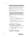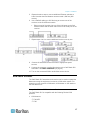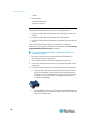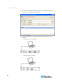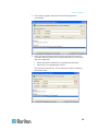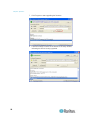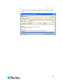
1
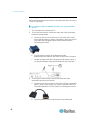
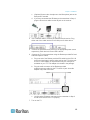
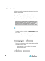
Cat5 Reach DVI User Guide Release 1.0 Copyright © 2013 Raritan, Inc. Cat5ReachDVI-0B-v1.0-E December 2013 255-80-0030-00 This document contains proprietary information that is protected by copyright. All rights reserved. No part of this document may be photocopied, reproduced, or translated into another language without express prior written consent of Raritan, Inc. © Copyright 2013 Raritan, Inc. All third-party software and hardware mentioned in this document are registered trademarks or trademarks of and are the property of their respective holders. FCC Information This Equipment has been tested and found to comply with the limits for a Class B digital device, pursuant to Part 15 of the FCC rules. These limits are designed to provide reasonable protection against harmful interference in a residential installation. This equipment generates, uses and can radiate radio frequency energy and, if not installed and used in accordance with the instructions, may cause harmful interference to radio communications. However, there is no guarantee that interference will not occur in a particular installation. If this equipment does cause harmful interference to radio or television reception, which can be determined by turning the equipment off and on, the user is encouraged to try to correct the interference by one or more of the following measures: - Reorient or relocate the receiving antenna. - Increase the separation between the equipment and receiver. - Connect the equipment into an outlet on a circuit different from that to which the receiver is connected. - Consult the dealer or an experienced radio/TV technician for help. VCCI Information (Japan) Raritan is not responsible for damage to this product resulting from accident, disaster, misuse, abuse, non-Raritan modification of the product, or other events outside of Raritan's reasonable control or not arising under normal operating conditions. If a power cable is included with this product, it must be used exclusively for this product. Contents Chapter 1 Introduction 1 Product Features ........................................................................................................................... 2 Package Contents.......................................................................................................................... 3 Product Overview........................................................................................................................... 3 Cat5 Reach DVI Transmitter.......................................................................................................... 3 Front View............................................................................................................................ 4 Rear View ............................................................................................................................ 5 Cat5 Reach DVI Receiver.............................................................................................................. 6 Front View............................................................................................................................ 6 Rear View ............................................................................................................................ 6 Chapter 2 Installation 8 Basic Installation ............................................................................................................................ 8 Connecting a Keyboard/Mouse/Video Source .................................................................... 9 Connecting an Audio/Video Device ................................................................................... 12 Advanced Installation................................................................................................................... 14 Increasing the Distance via Ethernet Switches or Hubs.................................................... 14 One Transmitter with Multiple Receivers Connected ........................................................ 16 KVM Switch Scenarios ................................................................................................................ 17 Compatible Raritan KVM Switches or Products ................................................................ 17 Connecting KVM Switches ................................................................................................ 18 iii Contents Audio Broadcasting...................................................................................................................... 21 Chapter 3 Operation 22 Enabling or Disabling the Remote Console................................................................................. 22 Using EDID to Synchronize Video Resolutions (Optional) .......................................................... 23 Firmware Upgrade ....................................................................................................................... 23 Appendix A Specifications 28 Cat5 Reach DVI Transmitter and Receiver ................................................................................. 28 DVI-to-VGA Adapters................................................................................................................... 30 Appendix B Rack Mounting Cat5 Reach DVI 31 Index 33 iv Chapter 1 Introduction The Cat5 Reach DVI KVM extender enables you to place your VGA or DVI monitor, USB keyboard, USB mouse, speakers, microphone and even an infrared (IR) remote control up to 3,000 feet (900 meters) away from your computer, server, KVM switch or an audio/video device like a TV or DVD player. There are two types of Cat5 Reach DVI devices: one is the transmitter (C5R-DVI-TX), and the other is the receiver (C5R-DVI-RX). In This Chapter Product Features .......................................................................................2 Package Contents .....................................................................................3 Product Overview ......................................................................................3 Cat5 Reach DVI Transmitter .....................................................................3 Cat5 Reach DVI Receiver .........................................................................6 1 Chapter 1: Introduction Product Features The Cat5 Reach DVI supports the following features: 2 Transmission of keyboard, mouse, video, audio and infrared (IR) remote control signals Support for both VGA and DVI video interfaces Support for the video resolutions up to Full HD 1080p (1920x1080@60Hz) Support for USB keyboard and mouse Dual console mode -- both local and remote consoles are enabled simultaneously by default Keyboard and mouse control on a first-come-first-served principle Capability to enable or disable the remote console Support for a maximum of 500-foot (150-meter) direct connection between the transmitter and receiver Capability to locate the transmitter and receiver up to 3,000 feet (900 meters) apart with the use of Ethernet switches or hubs IR (infrared) remote control for audio/video equipment, such as the TV or DVD player Support for multiple remote users Extended display identification data (EDID) emulation to synchronize video resolutions of a monitor Support for DDC and DDC2B Support for the touch screen Compatibility with common operating systems, including DOS, Windows, Linux, Mac OS/OSX and Sun Microsystems Support for the BIOS level operation Plug and play Support for Microsoft Intellimouse 3- to 5-key mouse and Microsoft Natural Keyboard Pro series Support for SUN Microsystems function key mapping Support for excellent USB HID emulation for the majority of HID devices Chapter 1: Introduction Package Contents Unpack the components. If anything is missing or damaged, contact the local dealer or Raritan Technical Support for help. Items Quantity C5R-DVI-TX transmitter 1 C5R-DVI-RX receiver 1 DVI cable 1 DC 5V 2A power adapter 2 DVI-I to VGA adapter* 2 1.8-meter audio/microphone cable 1 1.8-meter infrared (IR) receiver cable 1 1.8-meter infrared (IR) blaster cable 1 1.8-meter USB-B to USB-A adapter cable 1 Rackmount kit 1 Quick Setup Guide 1 Warranty card 1 *Note: The included DVI-I to VGA adapters are used with the C5R-DVI-TX transmitter, not the C5R-DVI-RX receiver. You need to purchase Raritan's DVI-D to VGA adapter (CVT-DVI-VGA) in order to connect a VGA monitor to the receiver. Product Overview This section describes the ports or components implemented on the Cat5 Reach DVI transmitter and receiver. Cat5 Reach DVI Transmitter The transmitter is connected to a computer, server, KVM switch or multimedia device. 3 Chapter 1: Introduction Front View On the front panel, the USB ports designed for the local console are marked with a white frame for easy identification. Number 4 Component Description Local USB Mouse Port Used to set up a local console. Local USB Keyboard Port Used to set up a local console. Audio In Connect to the Audio Out jack of a computer or TV, or connect speakers for audio output. Microphone Jack Connect to the Microphone jack of a computer, or connect a microphone. IR Jack Connect an IR blaster. RX LED (red) Indicate the remote console state. Connect a USB mouse, or connect to the USB Mouse port of a KVM drawer or user station. Connect a USB keyboard, or connect to the USB Keyboard port of a KVM drawer or user station. On: The remote console is enabled so you can operate it. Off: The remote console is disabled so you cannot operate it. TX LED (green) As the local console is enabled all the time, this LED is always lit as long as there is power supply. LINK LED (green) Indicate the cable connection status between the transmitter and receiver. On: The physical connection to the receiver is detected. Off: No physical connection to the receiver is detected. Chapter 1: Introduction Number Component Description Power LED (red) Indicate the power state. On: The transmitter is powered on. Off: The transmitter is powered off. REMOTE button Press this button to enable or disable the remote console. Rear View On the back panel, the DVI port used for the local console is marked with a white frame for easy identification. Number Items Description Power Input Connect the power adapter. Local Video (DVI-I OUT) Connect a VGA or DVI monitor, or connect to the Video In port of a KVM drawer or user station. Note: A DVI-to-VGA converter is required if using a VGA monitor. The DVI-I to VGA adapters, which are used on the transmitter, are included in the package, but you need to purchase the DVI-D to VGA cable, which is used on the receiver. DVI-I IN Port Connect to the VGA or DVI port of the IT device or an audio/video source such as the TV. USB-B Port Connect to the USB-A port of the IT device for USB keyboard/mouse inputs. RJ-45 LINK Port Connect to the receiver via a Cat5e/6 cable. There are two tiny LEDs adjacent to this port. F/W Upgrade Port Green indicates a physical link and activity. Yellow indicates communications at 10/100 BaseT speeds. Used to upgrade the firmware of the transmitter. 5 Chapter 1: Introduction Cat5 Reach DVI Receiver The receiver is connected to the remote console. Front View Number Items Description LINK LED (green) Indicate the cable connection status between the transmitter and receiver. Power LED (red) On: The physical connection to the transmitter is detected. Off: No physical connection to the transmitter is detected. Indicate the power state. On: The receiver is powered on. Off: The receiver is powered off. EDID button Press the EDID button only when you need to synchronize the video resolutions. Items Description Power Input Connect the power adapter. Audio Out Connect speakers. Microphone Jack Connect a microphone. Rear View Number 6 Chapter 1: Introduction Number Items Description DVI-D OUT Used to set up a remote console. Connect a VGA or DVI monitor, or connect to the Video In port of a KVM drawer or user station. Note: A DVI-to-VGA converter is required if using a VGA monitor. The DVI-I to VGA adapters, which are used on the transmitter, are included in the package, but you need to purchase the DVI-D to VGA cable, which is used on the receiver. USB Mouse Port Used to set up a remote console. Connect a USB mouse, or connect to the USB Mouse port of a KVM drawer or user station. USB Keyboard Port Used to set up a remote console. IR Jack Connect the IR receiver. Connect a USB keyboard, or connect to the USB Keyboard port of a KVM drawer or user station. RJ-45 LINK Port Connect to the transmitter via a Cat5e/6 cable. There are two tiny LEDs adjacent to this port. F/W Upgrade Port Green indicates a physical link and activity. Yellow indicates communications at 10/100 BaseT speeds. Used to upgrade the firmware of the receiver. 7 Chapter 2 Installation This section provides instructions on how to install the Cat5 Reach DVI in various ways. For example, you can connect the transmitter to one receiver only or to multiple receivers. In This Chapter Basic Installation........................................................................................8 Advanced Installation ..............................................................................14 KVM Switch Scenarios ............................................................................17 Audio Broadcasting .................................................................................21 Basic Installation The basic configuration consists of one transmitter, one receiver and one Cat5e/6 cable. The maximum cable length permitted between the transmitter and receiver is 500 feet (150 meters). Connect the keyboard/mouse/video (KVM) or audio/video source to the transmitter, and you will be able to control it remotely through the receiver. Tip: To expand the number of remote users or the distance between the transmitter and receiver, see Advanced Installation (on page 14). Below lists the equipment that can be connected to the Cat5 Reach DVI transmitter as the source device. Devices transmitting KVM signals, including (but not limited to): - A computer or server - A KVM switch - A computer workstation - A Paragon enhanced user station Devices transmitting audio/video signals, including (but not limited to): - A TV set - A DVD player 8 Chapter 2: Installation You would connect these devices to the Cat5 Reach DVI receiver. A set of USB keyboard, USB mouse, and VGA or DVI monitor Speakers A microphone A KVM switch A KVM drawer Tip: You could also connect the IR receiver as needed. Connecting a Keyboard/Mouse/Video Source This section illustrates the connection to a device that sends keyboard/mouse/video signals, such as a computer. For a list of compatible keyboards and mice, see the release notes available on the Raritan website's Firmware and Documentation section (http://www.raritan.com/support/firmware-and-documentation/).. To configure a basic installation for a computer: 1. Turn off all devices, including the desired computer. 2. (Optional) To set up a local console, connect the KVM input/output devices to the transmitter. a. Connect a USB mouse to the USB Mouse port on the front panel. b. Connect a USB keyboard to the USB Keyboard port on the front panel. c. Connect a VGA or DVI monitor to the Local Video (DVI-I OUT) port on the back panel. If using a VGA monitor, plug in the DVI-I to VGA cable that is shipped with the Cat5 Reach DVI before connecting the monitor. 9 Chapter 2: Installation d. (Optional) If the audio function is needed, connect one end of the Raritan-provided audio/microphone cable to the Audio In and Microphone jacks on the front panel. 3. To set up the remote console , connect KVM input/output devices to the receiver. a. Connect a USB mouse to the USB Mouse port on the back panel. b. Connect a USB keyboard to the USB Keyboard port on the back panel. c. Connect a VGA or DVI monitor to the DVI-D OUT port on the back panel. If using a VGA monitor, you need to purchase a DVI-D to VGA cable (Raritan's CVT-DVI-VGA) for connecting the monitor. d. (Optional) For the audio function, connect the speakers and microphone to the Audio Out and Microphone In jacks on the back panel. 10 Chapter 2: Installation 4. Use a Cat5e/6 cable to connect the transmitter and receiver. Plug either end of the cable into the RJ-45 LINK port of either device. 5. Connect the transmitter and receiver to an appropriate power source respectively. Each device's Power LED is then lit. 6. Connect the computer to the transmitter. a. Plug one end of the Raritan-provided DVI cable into the DVI IN port on the back panel, and the other end into the computer's video port. A DVI-I to VGA adapter is required if only the VGA port is available on your computer. This adapter is included in the package. b. Plug the USB-B connector of the Raritan-provided USB cable into the USB-B port on the back panel, and the other end into the computer's USB-A port. c. (Optional) If the audio/microphone cable has been connected to the transmitter in Step 2, plug the other end of the audio/microphone cable into the computer's Audio In and Microphone In jacks. 7. Turn on the computer. Note: If the monitor connected to the Cat5 Reach DVI does not show the correct resolution, press the EDID button to synchronize the correct video resolution. See Using EDID to Synchronize Video Resolutions (Optional) (on page 23). 11 Chapter 2: Installation Connecting an Audio/Video Device This section illustrates the connection to an audio/video device such as a TV set or DVD player. To configure a basic installation for the TV or any audio/video device: 1. Turn off all devices, including the TV. 2. To set up a local console, connect the audio and video input/output devices to the transmitter. a. Connect a VGA or DVI monitor to the Local Video (DVI-I OUT) port on the back panel. If using a VGA monitor, plug in the DVI-I to VGA cable that is shipped with the Cat5 Reach DVI before connecting the monitor. b. Plug the audio connector of the Raritan-provided audio/microphone cable into the Audio In jack on the front panel. c. Usually an audio/video device supports the IR remote control. If so, plug the IR blaster cable into the IR jack on the front panel. 3. To set up the remote console, connect the audio and video input/output devices to the receiver. a. Connect a VGA or DVI monitor to the DVI-D OUT port on the back panel. If using a VGA monitor, you need to purchase a DVI-D to VGA cable (Raritan's CVT-DVI-VGA) for connecting the monitor. b. Connect speakers to the Audio Out jack on the back panel. 12 Chapter 2: Installation c. (Optional) Connect the microphone to the Microphone jack on the back panel if needed. d. If you have connected the IR blaster to the transmitter in Step 2, plug the IR receiver cable into the IR jack on the receiver. 4. Use a Cat5e/6 cable to connect the transmitter and receiver. Plug either end of the cable into the RJ-45 LINK port of either device. 5. Connect the transmitter and receiver to an appropriate power source respectively. Each device's Power LED is then lit. 6. Connect the TV to the transmitter using the Raritan-provided DVI and audio/microphone cables. a. Plug one end of the Raritan-provided DVI cable into the DVI-I IN port on the back panel, and the other end into the TV's video port. A DVI-I to VGA adapter is required when only the VGA port is available on your TV. This adapter is included in the package. b. Plug the audio connector of the Raritan-provided audio/microphone cable into the TV's Audio In jack. An audio adapter may need to be used. c. Verify that the IR blaster connected to the transmitter in Step 2 aim at the IR sensor of the TV properly. 7. Turn on the TV. 13 Chapter 2: Installation Advanced Installation In this section, you will learn how to maximize the distance between the transmitter and receiver using Ethernet switches or hubs, or increase the number of remote consoles. Increasing the Distance via Ethernet Switches or Hubs The maximum length of the Cat5e/6 cable connected directly between a transmitter and a receiver is limited to 500 feet (150 meters). You can expand the distance up to 3,000 feet (900 meters) by daisy-chaining Ethernet switches or hubs in between. Warning: You CANNOT connect additional devices or utility to the remaining ports of any Ethernet switch connected between the Cat5 Reach DVI transmitter and receiver, or there will be communication problems between them. Select an entry level or non-managed Ethernet switch. Turn on the broadcast mode of the Ethernet switch before use. To extend the distance via Ethernet switches or hubs: 1. Turn off all devices. 2. Set up an optional local console with the transmitter, and a remote console with the receiver. For details, see Basic Installation (on page 8) for details. 3. Use a Cat5e/6 cable up to 500 feet (150 meters) long to connect the transmitter to an Ethernet switch. Plug one end of the cable into the RJ-45 LINK port on the transmitter and the other end into the LINK port on the Ethernet switch. 4. To increase the distance, use an additional Cat5e/6 cable up to 500 feet long to connect the Ethernet switch attached with the transmitter to an additional Ethernet switch. 14 Plug one end of the cable into one of the LAN ports on the prior Ethernet switch and the other end into the LINK port on the subsequent Ethernet switch. Chapter 2: Installation 5. Repeat the above step to connect additional Ethernet switches or hubs. Note that the total distance cannot exceed 3,000 feet (900 meters). 6. Use a Cat5e/6 cable up to 500 feet long to connect the receiver to the final Ethernet switch. Plug one end of the cable into one of the LAN ports on the final Ethernet switch and the other end into the RJ-45 LINK port on the receiver. The diagram below illustrates the connection pattern. 7. Connect the transmitter and receiver to an appropriate power source respectively. Each device's Power LED is then lit. 8. Connect the computer or audio/video device to the Cat5 Reach DVI transmitter. See Basic Installation (on page 8). 9. Turn on the connected computer or audio/video device. 15 Chapter 2: Installation One Transmitter with Multiple Receivers Connected One transmitter can be connected to multiple receivers so that more than one remote user can view and control the connected computer or audio/video device. This configuration requires the use of at least one Ethernet switch. The maximum distance between the transmitter and any receiver can be 2,000 feet (600 meters) by daisy-chaining Ethernet switches or hubs. When attaching keyboards and mice to the receivers, you must use the same brand and model of keyboards and mice for all receivers. Otherwise, there may be operational issues. Warning: You CANNOT connect additional devices or utility to the remaining ports of any Ethernet switch connected between the Cat5 Reach DVI transmitter and receiver, or there will be communication problems between them. Select an entry level or non-managed Ethernet switch. Turn on the broadcast mode of the Ethernet switch before use. To connect multiple receivers: 1. Turn off all devices. 2. Set up a local console with the transmitter, and a remote console with all receivers. For details, see Basic Installation (on page 8) for details. 3. Use a Cat5e/6 cable up to 500 feet (150 meters) long to connect the transmitter to an Ethernet switch. Plug one end of the cable into the RJ-45 LINK port on the transmitter and the other end into the LINK port on the Ethernet switch. 4. If intending to expand the distance, use an additional Cat5e/6 cable up to 500 feet long to connect the Ethernet switch attached with the transmitter to an additional Ethernet switch. 16 Plug one end of the cable into one of the LAN ports on the prior Ethernet switch and the other end into the LINK port on the subsequent Ethernet switch. Chapter 2: Installation 5. Repeat the above step to connect additional Ethernet switches or hubs. Note that the total distance cannot exceed 1,968 feet (600 meters). 6. Use a Cat5e/6 cable up to 500 feet long to connect one of the receivers to the final Ethernet switch. Plug one end of the cable into one of the LAN ports on the final Ethernet switch and the other end into the RJ-45 LINK port on the receiver. 7. Repeat steps 4 to 6 to connect additional receivers one by one. 8. Connect the transmitter and all receivers to appropriate power sources. 9. Connect the computer or audio/video device to the Cat5 Reach DVI transmitter. See Basic Installation (on page 8). 10. Turn on the connected KVM or audio/video source device. KVM Switch Scenarios The Cat5 Reach DVI transmitter and receiver can be used to expand the distances among the equipment involved in a KVM switch system. For example, you can connect a KVM switch, KVM drawer or user station to the Cat5 Reach DVI. Compatible Raritan KVM Switches or Products The Cat5 Reach DVI is compatible with the following Raritan KVM products. KVM drawers: - T1700-LED - T1700 17 Chapter 2: Installation - T1900 KVM switches: - Dominion KX II series - Dominion LX series Connecting KVM Switches This section introduces three scenarios involving KVM switches. Connect the Cat5 Reach DVI between any KVM switch and its local console. Connect the Cat5 Reach DVI between two KVM switches. Connect the Cat5 Reach DVI between a computer/server and a KVM switch. Turn off all devices before making the connections. For detailed information on setting up the local and remote consoles, see Connecting a Keyboard/Mouse/Video Source (on page 9). To increase the distance between a KVM switch and its user console/user station: 1. Set up the local and remote consoles with the Cat5 Reach DVI transmitter and receiver respectively. 2. Use a Cat5e/6 cable to connect the transmitter and receiver. 3. Connect the transmitter and receiver to an appropriate power source respectively. 4. Connect the local console ports of the KVM switch to the transmitter. a. Plug one end of the Raritan-provided DVI cable into the DVI-I IN port on the transmitter, and the other end into the KVM switch's video port. A DVI-I to VGA adapter is required if only the VGA port is available on your KVM switch. This adapter shown below is included in the package. b. Plug the USB-B connector of the Raritan-provided USB cable into the USB-B port on the transmitter, and the other end into the KVM switch's local USB-A port. 18 Chapter 2: Installation 5. Turn on the KVM switch. Tip: The local or remote console can be equipped with a KVM drawer instead of a set of keyboard, mouse and monitor. See the illustration below. To increase the distance between two tiering KVM switches: 1. Set up a remote console by connecting the receiver to a KVM switch. a. Connect a USB CIM to the receiver. b. Connect this USB CIM to any channel port on the KVM switch via a Cat5 cable. 2. Use a Cat5e/6 cable to connect the transmitter and receiver. 3. Connect the transmitter and receiver to an appropriate power source respectively. 4. Connect the KVM switch to the transmitter. 19 Chapter 2: Installation 5. Turn on both KVM switches. To increase the distance between any computer and a KVM switch: 1. Set up an optional local console with the transmitter. 2. Set up a remote console by connecting the receiver to a KVM switch. 3. Use a Cat5e/6 cable to connect the transmitter and receiver. 4. Connect the transmitter and receiver to an appropriate power source respectively. 5. Connect the computer to the transmitter. 6. Turn on the computer. 20 Chapter 2: Installation Audio Broadcasting Bi-directional audio transmission capability of the Cat5 Reach DVI allows you to create an audio broadcasting system between the transmitter and its receiver(s). All you need to do is connect speakers and microphones to both the transmitter and receiver(s). The audio signals input from the microphone connected to the transmitter is transmitted to the speakers connected to the receiver, and vice versa. To establish an audio broadcasting system between the Cat5 Reach DVI devices: 1. Turn off all devices. 2. Connect the microphone and speaker to the Audio In and Microphone Out jacks of the transmitter. When audio broadcasting, speaker must be connected to microphone jack and microphone must be connected to audio jack. 3. Connect the speakers and microphone to the Audio Out and Microphone In jacks of the receiver. 4. Use a Cat5e/6 cable to connect the transmitter and receiver. Plug either end of the cable into the RJ-45 LINK port of either device. 5. Connect the transmitter and receiver to an appropriate power source respectively. Each device's Power LED is then lit. 6. Turn on all speakers and microphones. 21 Chapter 3 Operation After finishing the hardware installation of the transmitter and receiver(s), you can start operating either the local or remote console, or maintain both Cat5 Reach DVI devices by upgrading their firmware. In This Chapter Enabling or Disabling the Remote Console.............................................22 Using EDID to Synchronize Video Resolutions (Optional)......................23 Firmware Upgrade...................................................................................23 Enabling or Disabling the Remote Console The factory default is to enable the remote console, and the keyboard and mouse control is determined on a first-come-first-served basis. To prevent the local console operation from being disturbed by a remote user, you can disable the remote console and re-enable it after completing your local operation. To disable the remote console: 1. Press the REMOTE button on the transmitter. 2. Verify that the RX LED turns OFF, indicating that the remote console has been disabled. To enable the remote console: 1. Press the REMOTE button on the transmitter again. 2. Verify that the RX LED turns ON, indicating that the remote console has been enabled. 22 Chapter 3: Operation Using EDID to Synchronize Video Resolutions (Optional) If you are using any KVM switch that does not support DDC, the connected equipment may not be able to show the correct video resolutions based on the video resolutions supported by the monitor. When this issue occurs on a DVI PC or a DVI KVM switch, use a pointed tip to press the EDID button on the receiver to learn the proper video resolution from the connected receiver's monitor. When this issue occurs on a VGA PC or a VGA KVM switch, press the EDID button and hold for 3 seconds to adjust the correct resolution from the connected receiver's monitor. Firmware Upgrade You can upgrade the firmware of both the Cat5 Reach DVI transmitter and receiver by connecting either device to a computer running the firmware upgrade utility. Unless otherwise specified, both the transmitter and receiver should be upgraded with the same firmware file . The Cat5 Reach DVI firmware files are available on the Raritan website's Firmware and Documentation section (http://www.raritan.com/support/firmware-and-documentation/). You need to upgrade the firmware only when there are keyboard and mouse incompatibility issues with the Cat5 Reach DVI. To upgrade the firmware of either Cat5 Reach DVI device: 1. Disconnect all cables from the Cat5 Reach DVI extenders. 2. Connect the Cat5 Reach DVI device to the power source. 23 Chapter 3: Operation 3. Run the firmware upgrade utility "Prog.exe" on a computer that will be connected to the Cat5 Reach DVI device. 4. Use a mini-USB cable to connect the Cat5 Reach DVI device to the computer. 24 Connection to the transmitter: Connection to the receiver: Chapter 3: Operation 5. The firmware upgrade utility will scan the KVM programmer automatically. 6. Select the target programmer(s) that will be updated. Note that the transmitter has two programmers implemented while the receiver has only one programmer. Select both MCU1 and MCU2 for upgrading the transmitter. Select MCU1 for upgrading the receiver. Then select the firmware file. The file selected for MCU1 and MCU2 must be the same. 25 Chapter 3: Operation 7. Click Program to start upgrading the firmware. 8. A status message is shown at the bottom of the utility window, indicating the device is being upgraded. 26 Chapter 3: Operation 9. When the firmware is updated successfully, the utility shows "Program OK." 27 Appendix A Specifications This section provides the specifications of the Cat5 Reach DVI transmitter, receiver and two types of DVI-to-VGA adapters. In This Chapter Cat5 Reach DVI Transmitter and Receiver .............................................28 DVI-to-VGA Adapters ..............................................................................30 Cat5 Reach DVI Transmitter and Receiver Items Console connectors PC connectors Extension port LEDs Transmitter Receiver Video out 1 x DVI-I 1 x DVI-D Keyboard 1 x USB type A 1 x USB type A Mouse 1 x USB type A 1 x USB type A Speakers 1 x audio jack (pink) 1 x audio jack (pink) Microphone 1 x audio jack (green) 1 x audio jack (green) IR (infrared) Blaster Receiver Video in 1 x DVI-I N/A USB USB type B N/A RJ-45 For communications of keyboard, mouse, video, audio, and IR signals RX active Red LED N/A TX active Green LED N/A Power Red LED Red LED Link Green LED Green LED 28 Appendix A: Specifications Items Transmitter Receiver Console switch button Switching sequence: Transmitter, Transmitter + Receiver N/A Support for DDC/DDC2 monitors Connection cable type and max. cable length Max. resolution Supports DDC, DDC2B Cat5e/6 cable up to 500 feet (150 meters) long Full HD 1080p (1920x1080@60Hz) 1920x1080@60Hz 1680x1050@60Hz 1440x900@60Hz 1280x1024@60Hz 1152x864@60Hz; 75Hz 1024x768@60Hz;70Hz 800x600@60Hz Video Resolution Supported operating systems Power supply Dimension Housing material Operating temperature Humidity Safety Warranty 640x480@60Hz Windows, Linux, Mac OS/OSX and Sun Microsystems DC 5V 2A power adapter 7.09'' x 3.31'' x 1.42'' 180 x 84 x 36 mm Metal 32-122 (0-50 ) 0-80% RH FCC, CE, VCCI and RoHS 2 years 29 Appendix A: Specifications DVI-to-VGA Adapters A DVI-to-VGA adapter is required when connecting a VGA monitor (or computer) to the Cat5 Reach DVI. There are two types of DVI-to-VGA adapters: one is the DVI-I to VGA adapter, which works with the Cat5 Reach DVI transmitter, and the other is the DVI-D to VGA cable, which works with the receiver. DVI-I to VGA Adapter Items Connector types Availability Description DVI-I x1 VGA x1 2 units included in the product package DVI-D to VGA Cable Items Connector types Availability 30 Description DVI-D x1 VGA x1 NOT included in the product package so you need to purchase it Appendix B Rack Mounting Cat5 Reach DVI Cat5 Reach DVI transmitter and receiver can be mounted in a standard rack. To rack mount a transmitter or a receiver, use the brackets and screws in the package. You can mount the Cat5 Reach DVI units facing the front of the rack or the rear. To rack mount Cat5 Reach DVI: 1. Secure the bracket to the unit (transmitter or receiver) with three of the included screws. Only one bracket for each unit. Choose to lock the bracket at the right side or left side of the unit, depending on which side you want to install on the rack. 2. Mount the unit in the rack, and secure the brackets' ears to the rack's front rails with the rack mount screws, bolts, or cage nuts. 31 Index A Advanced Installation • 8, 14 Audio Broadcasting • 21 Operation • 22 P B Package Contents • 3 Product Features • 2 Product Overview • 3 Basic Installation • 8, 14, 15, 16, 17 R C Cat5 Reach DVI Receiver • 6 Cat5 Reach DVI Transmitter • 3 Cat5 Reach DVI Transmitter and Receiver • 28 Compatible Raritan KVM Switches or Products • 17 Connecting a Keyboard/Mouse/Video Source • 9, 18 Connecting an Audio/Video Device • 12 Connecting KVM Switches • 18 Rack Mounting Cat5 Reach DVI • 31 Rear View • 5, 6 S Specifications • 28 U Using EDID to Synchronize Video Resolutions (Optional) • 11, 23 D DVI-to-VGA Adapters • 30 E Enabling or Disabling the Remote Console • 22 F Firmware Upgrade • 23 Front View • 4, 6 I Increasing the Distance via Ethernet Switches or Hubs • 14 Installation • 8 Introduction • 1 K KVM Switch Scenarios • 17 O One Transmitter with Multiple Receivers Connected • 16 33 U.S./Canada/Latin America Monday - Friday 8 a.m. - 6 p.m. ET Phone: 800-724-8090 or 732-764-8886 For CommandCenter NOC: Press 6, then Press 1 For CommandCenter Secure Gateway: Press 6, then Press 2 Fax: 732-764-8887 Email for CommandCenter NOC: [email protected] Email for all other products: [email protected] China Europe Europe Monday - Friday 8:30 a.m. - 5 p.m. GMT+1 CET Phone: +31-10-2844040 Email: [email protected] United Kingdom Monday - Friday 8:30 a.m. to 5 p.m. GMT Phone +44(0)20-7090-1390 Beijing France Monday - Friday 9 a.m. - 6 p.m. local time Phone: +86-10-88091890 Monday - Friday 8:30 a.m. - 5 p.m. GMT+1 CET Phone: +33-1-47-56-20-39 Shanghai Germany Monday - Friday 9 a.m. - 6 p.m. local time Phone: +86-21-5425-2499 Monday - Friday 8:30 a.m. - 5:30 p.m. GMT+1 CET Phone: +49-20-17-47-98-0 Email: [email protected] GuangZhou Monday - Friday 9 a.m. - 6 p.m. local time Phone: +86-20-8755-5561 India Monday - Friday 9 a.m. - 6 p.m. local time Phone: +91-124-410-7881 Japan Monday - Friday 9:30 a.m. - 5:30 p.m. local time Phone: +81-3-5795-3170 Email: [email protected] Melbourne, Australia Monday - Friday 9:00 a.m. - 6 p.m. local time Phone: +61-3-9866-6887 Taiwan Monday - Friday 9 a.m. - 6 p.m. GMT -5 Standard -4 Daylight Phone: +886-2-8919-1333 Email: [email protected]