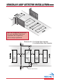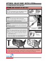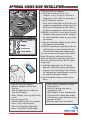
1
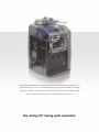
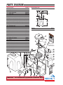
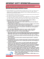
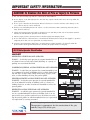
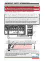
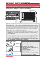
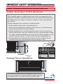
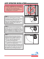
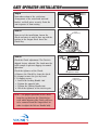
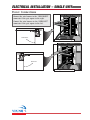
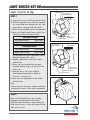
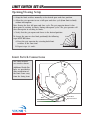
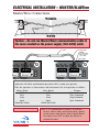
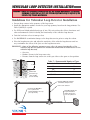
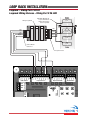
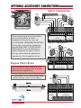
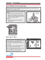
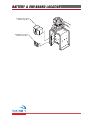
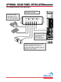
VIKING
installation instructions
and safety information
VIKING BLUE ENABLED
SOLAR EFFICIENT OPERATION
class I, class II, class III, and class IV
residential and commercial vehicular swing gate operator
1HP with battery backup are simple but powerful words describing the Viking T-21™
gate operator. The T-21™ is our heavy duty swing gate operator capable of handling
gates up to 1200 lbs. and 20’ long. Smooth efficient gate movement is achieved with
soft-start and soft-stop using the newest technology in electronics.
the viking T-21™swing gate operation
T-21 Vehicular Gate Operator • Revision B4 • November 2009
PARTS
PARTS DIAGRAM
DIAGRAM
Item Description
1 Output Shaft Knob
2 Output Shaft Cover
3 Clutch Key
4 Clutch and Handle
5 Output Arm
6 Output Shaft
7 Worm Gear #80 30:1
8 Sprocket 15 pitches, #50, 7/8 bore
9 Endless #50x36 Pitches
10 Sprocket 15 pitches, #50, 3/4 bore
11 24V 1 HP DC Motor/Gear Assembly
12 Spacer
13 Limit Cam & Holder
14 Limit switch (2)
15 Limit switch Holder
16 Limit Switch Bracket
17 Alarm
18 Electric Box
19 Control Board
20 Chassis
21 120V Receptacle
22 EMI Board
23 Battery Fuse Holder
24 Battery
25 Toroid Transformer
26 Limit Switch Harness
27 Power Harness
28 Operator Cover
29 Operator Cover Bolt
30 Power Switch
31 Warning Placard
32 Multi-Part Arm
28
Part No.
DWOUK10
T21OC10
VAWRCK20
DWCL20
DWAR20
DWOP10
T21GB80
T21SP507/8
T21CH50
T21SP503/4
VAT21MO
DWSPA10
DWLC10
DULS10
DWLH10
T21LH
DUAL10
DUEB10
DUPCB10
T21CHK
DUOL120
DUEMI10
VABFH
DUBA12
DUTT15
VALSWHA
VAF1PHA
T21CO10
VASWCB
DUMRS10
DUWPA
VA-F1ARM20
27
Overall Dimensions
20"
7-1/2"
EQ
EQ
28-1/4"
26-1/2"
17-3/4"
100 lb.
Weight
1
2
4
3
5
6
7
14
8
31
32 Multi-Part Arm
See Page 11 for
Additional Details
12
13
26
15
9
17
10
16
18
11
30
23
19
(2) 30
29
25
24
22
20
21
WARNING - For Installation By Qualified Personnel Only.
i
TECHNICAL SUPPORT 1 800 908 0884
TABLE
TABLE OF
OF CONTENTS
CONTENTS
Parts Diagram/Parts List . . . . . . . . . . . . . . . . . . . . . . . . . . . . . . . . . . . . . . . . . . .i
Important Safety Information
Important Safety Instructions . . . . . . . . . . . . . . . . . . . . . . . . . . . . . . . . . . . . . .2
Important Installation Instructions . . . . . . . . . . . . . . . . . . . . . . . . . . . . . . . . .2-3
Maintenance/General Safety Precautions . . . . . . . . . . . . . . . . . . . . . . . . . . . . . .4
To Reduce Risk of Fire or Personal Injury & Terminology . . . . . . . . . . . . . . . . . .5
Photo Beam (non-contact sensor) Installation . . . . . . . . . . . . . . . . . . . . . . . . . .6
Edge Sensor (contact sensor) Installation . . . . . . . . . . . . . . . . . . . . . . . . . . . . . .7
Manual Release . . . . . . . . . . . . . . . . . . . . . . . . . . . . . . . . . . . . . . . . . . . . . . . .7
Audible Alarm Reset Switch Installation . . . . . . . . . . . . . . . . . . . . . . . . . . . . . .8
Warning Placard Installation . . . . . . . . . . . . . . . . . . . . . . . . . . . . . . . . . . . . . .8
Important Installation Information . . . . . . . . . . . . . . . . . . . . . . . . . . . . . . . . . .9
Specifications . . . . . . . . . . . . . . . . . . . . . . . . . . . . . . . . . . . . . . . . . . . . . . . . .9
Plans of Installation . . . . . . . . . . . . . . . . . . . . . . . . . . . . . . . . . . . . . . . . . . . . . .10
Plan of Installation – Concrete Pads . . . . . . . . . . . . . . . . . . . . . . . . . . . . . . . . . .11
Gate Operator Installation
Step 1 through 6 – Operator Installation . . . . . . . . . . . . . . . . . . . . . . . . . . . .12-13
Electrical Installation
Electrical Installation . . . . . . . . . . . . . . . . . . . . . . . . . . . . . . . . . . . . . . . . . . . .14
Single Unit Connections . . . . . . . . . . . . . . . . . . . . . . . . . . . . . . . . . . . . . . . . .15
Gate Operator Installation
Step 6 – Limit Switch Setup . . . . . . . . . . . . . . . . . . . . . . . . . . . . . . . . . . . . .16-17
Limit Switch Connections . . . . . . . . . . . . . . . . . . . . . . . . . . . . . . . . . . . . . . . .17
Electrical Installation
VikingBlue Wireless Master/Slave Installation . . . . . . . . . . . . . . . . . . . . . . . . . .18
Master/Slave Connections . . . . . . . . . . . . . . . . . . . . . . . . . . . . . . . . . . . . . . . .19
Vehicular Loop Detector Installation
Loop Layout Diagrams . . . . . . . . . . . . . . . . . . . . . . . . . . . . . . . . . . . . . . . . . .20
Installation Guidelines . . . . . . . . . . . . . . . . . . . . . . . . . . . . . . . . . . . . . . . . . . .21
Loop Rack Installation . . . . . . . . . . . . . . . . . . . . . . . . . . . . . . . . . . . . . . . . . . .22
Accessory Connections
Open Commands; Safety Connections . . . . . . . . . . . . . . . . . . . . . . . . . . . . . . . .23
Radio Receiver . . . . . . . . . . . . . . . . . . . . . . . . . . . . . . . . . . . . . . . . . . . . . . . .24
Optional Viking Electromagnetic Lock . . . . . . . . . . . . . . . . . . . . . . . . . . . . . . .25
Magnetic Lock; Solenoid Connection; Guard Station . . . . . . . . . . . . . . . . . . . . .26
Special Features
Auto-Open Feature . . . . . . . . . . . . . . . . . . . . . . . . . . . . . . . . . . . . . . . . . . . . .27
Intelligent Obstruction Sensor (Primary Entrapment Protection) . . . . . . . . . . . . .28
Fail Safe/Fail Secure Operation; Hold Open Timer . . . . . . . . . . . . . . . . . . . . . . .29
Gate Overlap Setting . . . . . . . . . . . . . . . . . . . . . . . . . . . . . . . . . . . . . . . . . . . .30
Battery & EMI Board Location . . . . . . . . . . . . . . . . . . . . . . . . . . . . . . . . . . . . .31
Optional Solar Panel Installation . . . . . . . . . . . . . . . . . . . . . . . . . . . . . . . . . .32-33
Optional VikingBlue Installation . . . . . . . . . . . . . . . . . . . . . . . . . . . . . . . . . . . . .34
Troubleshooting . . . . . . . . . . . . . . . . . . . . . . . . . . . . . . . . . . . . . . . . . . . . . . . .35-37
TECHNICAL SUPPORT 1 800 908 0884
1
IMPORTANT
IMPORTANT SAFETY
SAFETY INFORMATION
INFORMATION
WARNING - Not following these instructions may cause severe injury or death to persons.
IMPORTANT SAFETY INSTRUCTIONS
WARNING – To reduce the risk of severe injury or death:
1. READ AND FOLLOW ALL INSTRUCTIONS.
2. Never let children operate or play with gate controls. Keep the remote control away from children.
3. Always keep people and objects away from the gate. NO ONE SHOULD CROSS THE PATH OF
THE MOVING GATE.
4. Test the gate operator monthly. The gate MUST reverse on contact with a rigid object or when
an object activates the non-contact sensors. After adjusting the force or the limit of travel,
retest the gate operator. Failure to adjust and retest the gate operator properly can increase the
risk of injury or death.
5. Use the manual release only when the gate is not moving.
6. KEEP GATES PROPERLY MAINTAINED. Read the owner’s manual. Have a qualified service person make repairs to gate hardware.
7. The entrance is for vehicles only. Pedestrians must use separate entrance.
8. Every gate operator installation MUST have secondary protection devices
against entrapment, such as edge sensors and photo beams more in particularly
in places where the risk of entrapment is more likely to occur.
9. SAVE THESE INSTRUCTIONS.
IMPORTANT INSTALLATION INSTRUCTIONS
1. Install the gate operator only when:
a) The operator is appropriate for the construction of the gate and the usage Class of the gate
(refer to page 5),
b) All openings of a horizontal slide gate are guarded or screened from the bottom of the gate
to a minimum of 4 feet (1.22 m) above the ground to prevent a 2-1/4 inch (57.2 mm)
diameter sphere from passing through the openings anywhere in the gate, and in that
portion of the adjacent fence that the gate covers in the open position,
c) ALL EXPOSED PINCH POINTS ARE ELIMINATED OR GUARDED, AND
d) GUARDING IS SUPPLIED FOR EXPOSED ROLLERS.
2. The operator is intended for installation only on gates used for vehicles. Pedestrians must be
supplied with a separate access opening. The pedestrian access opening shall be designed to
promote pedestrian usage. Locate the gate such that persons will not come in contact with the
vehicular gate during the entire path of travel of the vehicular gate.
3. The gate must be installed in a location so that enough clearance is supplied between the gate
and adjacent structures when opening and closing to reduce the risk of entrapment. Swinging
gates shall not open into public access areas.
4. The gate must be properly installed and work freely in both directions prior to the installation
of the gate operator. Do not over-tighten the operator clutch or pressure
relief valve to compensate for a damaged gate.
5. The gate operator controls must be placed so that the user has full view
of the gate area when the gate is moving AND AWAY FROM THE GATE
PATH PERIMETER,
2
TECHNICAL SUPPORT 1 800 908 0884
IMPORTANT
IMPORTANT SAFETY
SAFETY INFORMATION
INFORMATION
WARNING - Not following these instructions may cause severe injury or death to persons.
IMPORTANT INSTALLATION INSTRUCTIONS Continued
6. Controls intended for user activation must be located at least six feet (6’) away from any moving part of the gate and where the user is prevented from reaching over, under, around or
through the gate to operate the controls. Outdoor or easily accessible controls shall have a security feature to prevent unauthorized use.
7. The Stop and/or Reset button must be located in the line-of-sight of the gate. Activation of the
reset control shall not cause the operator to start.
8. All warning signs and placards must be installed where visible in the area of the gate. A minimum
of two placards shall be installed. A placard is to be installed in the area of each side of the
gate and be visible to persons located on the side of the gate on which the placard is installed.
9. For gate operators utilizing a non-contact sensor (Photo beam or like) in
accordance with section 31.1.1 of the UL325 standard:
a) See instructions on the placement of non-contact sensors for each Type of
application (refer to page 6),
b) Care shall be exercised to reduce the risk of nuisance tripping, such as when
a vehicle, trips the sensor while the gate is still moving, and
c) One or more non-contact sensors shall be located where the risk of entrapment
or obstruction exists, such as the perimeter reachable by a moving gate or
barrier (refer to page 6).
d) Use only Omron E3K-R10K4 photoelectric eye to comply with UL325
10. For a gate operator utilizing a contact sensor (Edge sensor or like) in
accordance with section 31.1.1 of the UL325 standard:
a) One or more contact sensors shall be located where the risk of entrapment or
obstruction exists, such as at the leading edge, trailing edge, and post mounted
both inside and outside of a vehicular horizontal slide gate (refer to page 7).
b) One or more contact sensors shall be located at the bottom edge of a vehicular
vertical lift gate.
c) One or more contact sensors shall be located at the pinch point of a vehicular
vertical pivot gate.
d) A hardwired contact sensor shall be located and its wiring arranged so that the
communication between the sensor and the gate operator is not subjected to
mechanical damage.
e) A wireless contact sensor such as one that transmits radio frequency (RF)
signals to the gate operator for entrapment protection functions shall be
located where the transmission of the signals are not obstructed or impeded
by building structures, natural landscaping or similar obstruction. A wireless
contact sensor shall function under the intended end-use conditions.
f) One or more contact sensors shall be located on the inside and outside leading
edge of a swing gate. Additionally, if the bottom edge of a swing gate is greater
than 6 inches (152 mm) above the ground at any point in its arc of travel, one
or more contact sensors shall be located on the bottom edge (refer to page 7).
g) One or more contact sensors shall be located at the bottom
edge of a vertical barrier (arm).
h) Use only Miller Edge Model MGR20 or MGS20 edge sensor
to comply with UL325
TECHNICAL SUPPORT 1 800 908 0884
3
IMPORTANT
IMPORTANT SAFETY
SAFETY INFORMATION
INFORMATION
WARNING - Not following these instructions may cause severe injury or death to persons.
MAINTENANCE
Remove the Power Harness from the Control Board (refer to page 15)
• Clean and lubricate the turning pins and gate hinges using the recommended lubricant.
• Check that all mounting hardware of the gate operator is properly tighten.
• Ensure that the gate moves freely.
• Check for corroded parts and replace if necessary.
• Check the battery for the following:
Battery connections must be free of corrosion.
Battery voltage must be 26 VDC (fully charged battery).
Reconnect the Power Harness for the Control Board (refer to page 15)
• Check and confirm the proper operation of all safety devices (photoelectric eye, edge sensors or like).
• Check and confirm the operation of all installed accessories.
• Check and confirm the operation of all special features such as the Intelligent Obstruction Sensor, Hold
Open Timer (refer to page 23 to 29)
• Check and confirm the operation of the manual release (refer to page 7)
• Verify battery backup functionally by turning off the power source (120 VAC and 220 VAC). DO NOT
FORGET TO TURN ON THE POWER SOURCE AFTER VERIFICATION.
GENERAL SAFETY PRECAUTIONS
The following precautions are an integral and essential part of the product and must be supplied to the user.
Read them carefully as they contain important indications for the safe installation, use and maintenance.
• These instruction must be kept and forwarded to all possible future users of the system.
• This product must be used only for that which it has been expressly designed.
• Any other use is to be considered improper and therefore dangerous.
• The manufacturer cannot be held responsible for possible damage caused by improper, erroneous or
unreasonable use.
• Avoid operating in the proximity of the hinges or moving mechanical parts.
• Do not enter the path of the moving gate while in motion.
• Do not obstruct the motion of the gate as this may cause a situation of danger.
• Do not allow children to play or stay within the the path of the moving gate.
• Keep remote control or any other control devices out of the reach of children, in order to avoid possible
involuntary activation of the gate operator.
• In case of break down or malfunctioning of the product, disconnect from the main power source. Do not
attempt to repair or intervene directly, contact only qualified personnel for repair.
• Failure to comply with the above may create a situation of danger.
• All cleaning, maintenance or repair work must be carried out by qualified personnel.
• In order to guarantee that the system works efficiently and correctly it is important to have the manufacturer’s
instructions on maintenance of the gate and operator carried out by qualified personnel.
• In particular, regular checks are recommended in order to verify that the safety devices are operating correctly.
All installation, maintenance and repair work must be documented and made available to the user.
Installer:
_____________________________________________________
____________
Signature
Date
Contact:
_________________________________________________________
_________________________________________________________
4
TECHNICAL SUPPORT 1 800 908 0884
IMPORTANT
IMPORTANT SAFETY
SAFETY INFORMATION
INFORMATION
CAUTION: To Reduce the Risk of Fire or Injury to Persons
a) Use only the following type and size of battery(ies): Yuasa NP7-12
b) Do not dispose of the battery(ies) in fire. The cells may explode. Check with local codes for possible disposal instructions.
c) Do not open or mutalate the battery(ies). Released electrolyte is corrosive and may cause damage to the
eyes or skin. It may be toxic fi swallowed.
d) Exercise care in handling batteries in order not to short the battery with conductying materials such as
rings, bracelets and keys.
e) Change the battery(ies) provided with or identified for use with this product only in accordance with the
instructions and limitations specified in this manual.
f) Observe proper polarity orientation between the battery(ies) and charging circuit.
g) Do not mix batteries of different sizes or from different manufacturers in this product (applies to products
employing more than one user replaceable secondary battery).
h) A battery-operated product employing a secondary battery supply intended to be charged within the
product shall contain specific instructions concerning the proper method of charging.
UL325 Gate Operator Classification
GLOSSARY
RESIDENTIAL VEHICULAR GATE OPERATOR
CLASS I – A vehicular gate operator (or system) intended for use
in a home of one-to four single family dwelling, or a garage or
parking area associated therewith.
COMMERCIAL/GENERAL ACCESS VEHICULAR GATE OPERATOR
CLASS II – A vehicular gate operator (or system) intended for use
in a commercial location or building such as a multi-family housing unit (five or more single family units), hotel, garages, retail
store, or other building servicing the general public.
INDUSTRIAL/LIMITED ACCESS VEHICULAR GATE OPERATOR
CLASS III – A vehicular gate operator (or system) intended for
use in an industrial location or building such as a factory or
loading dock area or other locations not intended to service the
general public.
RESTRICTED ACCESS VEHICULAR GATE OPERATOR
CLASS IV – A vehicular gate operator (or system) intended for
use in a guarded industrial location or building such as an airport security area or other restricted access locations not servicing the general public, in which unauthorized access is prevented
via supervision by security personnel.
Install the gate operator only when:
The operator is appropriate for the construction of the gate
and the Usage Class of the gate.
5
TECHNICAL SUPPORT 1 800 908 0884
5
IMPORTANT
IMPORTANT SAFETY
SAFETY INFORMATION
INFORMATION
WARNING - Not following these instructions may cause severe injury or death to persons.
NOTE - This type of installation DOES NOT reverse the gate all the way back to its limits when the photo-beam
is obstructed. This installation is only to protect against entrapment and to comply with UL325.
Photo Beam (non-contact sensor) Installation
Secondary Entrapment Protection
Photo beams or like must be installed to reduce the risk of entrapment.
Use only Omron E3K-R10K4 photoelectric eye to comply with UL325
Make the electrical connections of the photoelectric sensor as described here in this page.
Care shall be exercised to reduce the risk of nuisance tripping, such as when a
vehicle, trips the sensor while the gate is still moving, and
One or more non-contact sensors shall be located where the risk of entrapmentor
obstruction exists, such as the perimeter reachable by a moving gate or barrier.
Turn Switch to
'Light On' Position
GND
Close
Omron Model
Stop
Open
Gnd
Guard Station
24VDC
Fire
Gnd
Strike
Gnd
Exit
Gnd
Open Commands
Center
Gnd
Reopen
Gnd
E3K-R10
Open Commands
Shown
Guard Station
Safety Connector
Radio Statio
Connection '3' (NC1)
Limit
3
0
3
Overlap
Delay
Mag.
Lock
Hold Open
Timer
min.
Mot
MAX
Overlap Delay
Sensor
Obstruction
Center
Loop
TECHNICAL SUPPORT 1 800 908 0884
1.5
Sensor
Safety
Loop
UL
Sensor
Low
Pow
Radio
Rec.
Char
6
Center
Loop
arger
Safety
Loop
Radio
Rec.
Power
UL
Sens
One or more non-contact sensors shall be located where the risk of entrapment or
obstruction exists, such as the perimeter reachable by a moving gate or barrier.
Consult
the installation
manual
UL325 device (photo
1.5
Radio
UL
Safetyfor the
Center
beam or like) for detail information about the usage, Obstruction
Rec.
Sensor
Loop
Loop
Overlap Delay
Sensor
installation and maintenance.
attery
Close
Close
min.
Limit
0
MAX
Obstruction
ensor
Stop
Reflector
Stop
Hold Open
Timer
Open
Open
Potential
Entrapment
30sec
Area (Shaded)
Open
Hold Open
Timer
Mag.
Lock
30
Mag.
Lock
Photo Beam Unit
Gate in Open Position
Stop
1sec
60sec
60
off
24 VDC Power Connections
Close
24 VDC Power Connections
Off 1
N.C.
3
(NC1)
Connection '1' (C1)
Mag. Lock
COM
UL
Radio Station
N.O.
Gnd
+28v
Gnd
Radio
+28v
Gnd
Loop Connector
1
(C1)
IMPORTANT
IMPORTANT SAFETY
SAFETY INFORMATION
INFORMATION
WARNING - Not following these instructions may cause severe injury or death to persons.
Edge Sensor (contact sensor) Installation
Secondary Entrapment Protection
UL
Siren
Siren
GND
Close
Stop
Open
Master/Slave
GND
Close
Guard Station
Open Commands
Guard Station
UL
Siren
Master/Slave
60
Close
Close
Stop
Open
Limit
Close
Brake
Stop
Stop
Radio Station
Mag.
Lock
Hold Open
Timer
Hold Open
Timer
Open
Open
Mag.
Lock
Hold Open
Timer
30
30sec
Brake
Brake
Safety Connector
Off 1
60sec
off
1sec
Mag.
Lock
Stop
Open
Gnd
Fire
Gnd
Strike
Gnd
Exit
Gnd
Center
Gnd
Reopen
Gnd
N.C.
UL
COM
Open Commands
Mag. Lock
N.O.
Gnd
+28v
Gnd
+28v
Radio
Gnd
+28v
Loop Connector
Radio Station
3-Sided Edge Sensor
3-Sided Edge Sensor
Limit
Edge sensor or like must be installed to reduce the risk of entrapment.
3
3
1.5
Overlap
Delay
min.
MAX
Overlap Delay
Sensor
Sensor
Obstruction
Center
Loop
Center
Loop
Safety
Loop
Safety
Loop
UL
Sens
One or more contact sensors shall be located on the inside and outside leading edge
1.5
ULgate.
Safety
Center
of aRadio
swing
Additionally,
if
the bottom
edge of a swing gate is greater than 6
Obstruction
Rec.
Sensor
Loop
Loop
Overlap Delay
Sensor
inches (152 mm) above the ground at any point in its arc of travel, one or more
contact sensors shall be located on the bottom edge.
UL
Sensor
Radio
Rec.
Radio
Rec.
Motor Sensor
Low Battery
Power
Power
Charger
Charger
0
Low Battery
Use only Miller Edge 3-sided MAX
activation
type MGR20 or MDS20 to comply with UL325
min.
0
Obstruction
Motor Sensor
OPEN LEFT
OPEN RIGHT
1. A hardwired contact sensor shall be located and its wiring arranged so that the
communication between the sensor and the gate operator is not subjected to
mechanical damage.
2. A wireless contact sensor such as one that transmits radio frequency (RF) signals
to the gate operator for entrapment protection functions shall be located where
the transmission of the signals are not obstructed or impeded by building
structures, natural landscaping or similar obstruction. A wireless contact sensor
shall function under the intended end-use conditions.
Manual Release
Fail
Fail Safe/Secure
Safe/Secure
Remove Hat
Locking Handle
(in Unlocked
Position)
When manual operation is required:
1. Remove the Hat
2. Lift the Locking Handle.
3. Remove the Clutch Key
To reengage the gate operator:
1. Align the Clutch and the notches on the
Output Shaft.
2. Insert the Clutch Key.
3. Push down the Locking Handle.
4. Reattach the Hat.
Attention: Lock and release operations MUST
be performed with motor NOT RUNNING.
TECHNICAL SUPPORT 1 800 908 0884
7
IMPORTANT
IMPORTANT SAFETY
SAFETY INFORMATION
INFORMATION
WARNING - Not following these instructions may cause severe injury or death to persons.
Audible Alarm Reset Switch Installation
Manual Reset for the Audible Alarm
UL325 standard requires an audible alarm to go off after two consecutive events
detected by the primary entrapment protection of the gate operator (obstruction sensor).
The audible alarm will continue to sound for 5 minutes or until a stop command
gets actuated.
The Stop command can be actuated in two different forms
1. Using the Built in Stop switch on the Control Box or
2. Using an External Stop button within the sight of the gate, away from moving
parts of the gate and out of reach of children.
3. Controls intended for user activation must be located at least six feet (6’) away
from any moving part of the gate and where the user is prevented from reaching
over, under, around or through the gate to operate the controls. Outdoor or easily
accessible controls shall have a security feature to prevent unauthorized use.
4. The Stop and/or Reset button must be located in the line-of-sight of the gate.
Activation of the reset control shall not cause the operator to start.
N.O.
COM
STOP
P
STO
6'
5'
Minimum
UL
Siren
Siren
GND
Close
Stop
Master/Slave
Guard Station
Open Commands
Guard Station
Open
GND
Close
Stop
Open
Manual Stop
Open Commands
Button
Gnd
Fire
Gnd
Strike
Gnd
Exit
Gnd
Center
Gnd
Reopen
Gnd
UL
Gnd
+28v
Gnd
Safety Connector
Radio
+28v
Gnd
+28v
Radio Station
Loop Connector
Radio Station
UL
Siren
Master/Slave
off
1sec
60sec
60
Close
Stop
Open
0
3
Overlap
Delay
Mag.
Lock
Hold Open
Timer
min.
Motor Sensor
MAX
Low Battery
Center
Loop
Safety
Loop
Radio
Rec.
1.5
Overlap Delay
Sensor
Sensor
Obstruction
Center
Loop
Safety
Loop
UL
Sens
Power
Radio
UL
Safety beCenter
AllPower
Warning Signs
and Placards
must
installed where
visible in 1.5the area
Obstruction
Rec.
Sensor
Loop
Loop
Overlap Delay
Charger
Sensor
of the gate. A minimum of two placards shall be installed.
A placard is
to be installed in the area of each side of the gate and be visible.
UL
Sensor
Radio
Rec.
OPEN
Charger
OPEN
TECHNICAL SUPPORT 1 800 908 0884
8
Brake
Limit
3
Low Battery
Close
min.
Limit
0
MAX
Obstruction
Motor Sensor
Close
Stop
Hold Open
Timer
Stop
Open
Open
Mag.
Lock
Hold Open
Timer
30
30sec
Mag.
Lock
Brake
Brake
N.C.
Off 1
COM
Mag. Lock
N.O.
Warning
Placard Installation
IMPORTANT
IMPORTANT INSTALLATION
INSTALLATION INFORMATION
INFORMATION
CAUTION - FOR USE WITH GATES OF A MAXIMUM OF 12 FT IN LENGTH AND 2000 LBS.
IN WEIGHT OR 20 FT IN LENGTH AND 1200 LBS. IN WEIGHT.
WARNING - TO REDUCE THE RISK OF SEVERE INJURY OR DEATH TO PERSONS:
This is NOT a pedestrian gate operator
Do NOT Install the gate operator to lift gates
12'-0"
OPEN
STOP
CLOSE
2000 lb.
Control
Buttons
MAX.
20'-0"
Locate Control Buttons:
1200 lb.
1. Within sight of the gate,
MAX.
2. At a minimum height of 5 feet so
small children are not able to
reach it, and
2000 pounds maximum gate weight at
12’ maximum gate length.
1200 pounds maximum gate weight at
20’ maximum gate length
3. Away from all moving parts of
the gate.
Specifications
Maximum Gate Length:
Maximum Gate Weight:
Maximum Aperture Angle:
Power Requirements:
Operating Temperature:
20 feet at 1200 lbs., 12 feet at 2000 lbs.
2000 lbs. at 12 feet, 1200 lbs. at 20 feet
120 deg.
120 VAC Single Phase at 3 Amps
Or
220 VAC Single Phase at 1.5 Amps
-20°C (-4°F) to 70°C (158°F)
TECHNICAL SUPPORT 1 800 908 0884
9
PLANS
PLANS OF
OF INSTALLATION
INSTALLATION
The gate must be installed in a location so that enough clearance is supplied between the
gate and adjacent structures when opening and closing to reduce the risk of entrapment.
Swinging gates shall not open into public access areas.
Gate in Closed
Position
C
B
C = A + 12"
Outside
A
E=
(L x
E
0.6)
D=
L
L=
87
with " Maxim
Viki
ng A um
rm
(L x
D
0.4)
F
Inside
Gate in Open Position
The installation shown using the
Straight Arm Secondary Extension can
NOT be back-driven. If a back-driven
installation is required, an Elbow Arm
Secondary Extension can be used.
Contact Viking Access for availability.
*Note: The dimensions provided are
just a guideline. Each site may have
different geometries or possibilities of
installation. The key for installation is
to have "E" longer than "D" and to
adjust the arms such that the arm is
straight at the closed position.
Place the operator at the desired
location and check the measurements
of A and B.
Figure A
Plan of Installation
10
TECHNICAL SUPPORT 1 800 908 0884
PLAN
PLAN OF
OF INSTALLATION
INSTALLATION –– DETAILS
DETAILS
Concrete Pad
10"
3-1/4"
2-7/16"
2.5"
Recommended Area
for Conduit(s)
23-1/4"
11"
7-5/8"
Center of Output Shaft
Operator Cover
Operator Chassis
Gate Operator
Concrete Pad
20"
6" Minimum
Drill for a 1/2" x 3-1/2"
Red Head Anchor
(4) Places
2.5"
12"
Conduit Location
30"
Grade Level
See Note 2
Gate Operator Concrete Pad
1. Follow the local building code to determine the required depth of the concrete pad.
2. Pad measurements recommended by Viking Access Systems are at least 20” long,
20” wide and 30” deep to ensure the stable operation of the operator, and a
minimum of 6” above level grade to avoid any flooding of the machinery.
4. Provide a sufficient number of conduit pathways for all low power accessories
such as loop detector leads, maglock, non-contact sensors, contact sensors, safety
and other commands.Also provide conduit for the power supply (either 110 or
220 VAC). Extend the conduit the recommended height of 1” above the level of
the concrete pad. Install all conduit in the shaded area shown above.
Arm Assembly
Viking Part # VA-F1ARM
Viking Access Systems can supply an Elbow Arm
Secondary Extension to make the T-21 unit backdrivable. Contact Viking Access for availability.
Dimension D
on Page 10
Pivot Bracket
Dimension E
on Page 10
Primary Extension
Secondary Extension
TECHNICAL SUPPORT 1 800 908 0884
11
GATE
GATE OPERATOR
OPERATOR INSTALLATION
INSTALLATION
CAUTION - If mounting bar is not welded to
a frame member that runs the full length
of the gate, the gate operator may
damage the gate. Do not weld the bar or
backing plate to a few pickets.
STEP 1
Release the clutch (see page 7). Cut the
extension arms according to the desired plan
of installation (Figure A on page 10).
Note: Leave some additional material when
cutting the extension arms to allow for
additional adjustment.
Remove Excess
Extension Tube
STEP 2
Position the pieces of the articulated arm
with the gate in the closed position. Ensure
that the dimensions correspond to the chosen
plan of installation. Use C-clamps or tack-weld
pieces to aid in the pre-installation process.
STEP 3
With the clutch released, move the gate
manually from the completely open to the
completely closed position. Verify that:
A. The gate and arm combination can
provide the desired operation.
B. The arm does not bind in its movement,
especially in the open position.
Note: The total travel angle of the primary arm
on the output shaft determines the speed of the
gate operation. The smaller the travel angle,
the quicker the gate will open and close.
12
TECHNICAL SUPPORT 1 800 908 0884
16
GATE
GATE OPERATOR
OPERATOR INSTALLATION
INSTALLATION
Step 4
Upon observation of the satisfactory
arrangement of the articulated arm and
bracket, weld all pieces securely. Paint the
arm to protect it from rusting.
STEP 5
Upon test of the installation, loosen the
clutch and rotate it until it lines up with the
notches in the Output Shaft. Insert the
Clutch Key.
Insert
Clutch Key
STEP 6
Check the Clutch adjustment. The Clutch is
shipped factory adjusted. The clutch must be
tight enough to prevent slippage in normal
operation.
Check the tightness of the Clutch:
A. Remove the Clutch Key from the clutch.
B. Attempt to move the gate by hand.
C. If slippage occurs:
1. Loosen the Locking Handle 180°
2. Tighten the opposite bolt.
3. Tighten the Locking Handle 180°
4. Check the tightness of the clutch again.
Tighten the Clutch
Adjust the
Opposite Bolt
NOTE – For proper operation of the Clutch,
keep the gap between the Clutch halves
even when adjusting (the Clutch will have
to be removed from the Output Shaft in
order to adjust the Release Handle bolt).
17
TECHNICAL SUPPORT 1 800 908 0884
13
OPEN RIGHT
OPEN LEFT
ELECTRICAL
ELECTRICAL INSTALLATION
INSTALLATION
Caution – Do not connect the power harness to the board
until the installation is ready for verification.
Red
24VAC
Green
White
Auxiliary Power Connection.
See page 27 for further details.
Power Harness
Earth Ground
115V/220V
Power Switch
3A FUSE
Part # VAEMI
Power Ground
To
Transformer
Neutral
Hot
Fail
Safe/Secure
24V BAT
Black
The Gate Operator requires a single phase AC
line to operate and charge the batteries.
1. Turn off the main switch or breaker for
the power line being used.
2. Move the selector switch on the Incoming
Voltage Selector to the proper position
(115 for 110 to 120VAC, 230 for 200 to 240VAC).
3. Connect the incoming power wires to the
terminals as shown in the illustration.
4. Turn on the main switch or breaker once
the installation is ready for final
adjustments.
5. To verify that there is AC power to the
system, check that the ‘Charger’ LED on the
Control Board is on.
Tips for proper ground installation
A good ground in a gate operator
installation will minimize or prevent damage
to the operator cause by natural events such
as lightning strikes.
The following will provide a guideline for
proper grounding:
1. Use a ground rod to provide a ground
reference.
2. Consult your city code and be aware of
under-ground services in the site of the
gate operator to prevent inconveniences.
3. Use always a single bonding point for
grounding.
4. All ground wires must be as short and as
thick as possible.
5. Prevent unnecessary turns or loops in all
ground wires.
Earth Ground
Ground Rod
14
TECHNICAL SUPPORT 1 800 908 0884
18
Motor Sensor
ELECTRICAL
ELECTRICAL INSTALLATION
INSTALLATION –– SINGLE
SINGLE UNIT
UNIT
Low Battery
UL
Sensor
Power
Radio
Rec.
Charger
OPEN LEFT
OPEN RIGHT
Connect the wire harness to the “OPEN RIGHT”
connector if the gate opens to the right.
Connect the wire harness to the “OPEN LEFT”
connector if the gate opens to the left.
afety
Loop
Power Connections
Motor Sensor
OPEN RIGHT
Low Battery
UL
Sensor
Radio
Rec.
OPEN LEFT
Power
Charger
OPEN RIGHT
OPEN LEFT
Gate opens towards left
TECHNICAL SUPPORT 1 800 908 0884
15
Safety
Loop
Gate opens towards right
LIMIT
LIMIT SWITCH
SWITCH SET-UP
SET-UP
Limit Switch Setup
Cam Wheel
Clutch Guide Pin
Limit Switch Cam
STEP 7
A. Loosen the screws on the Limit Switch Cams.
B. With the operator cover still off, remount
the articulated arm, making sure the cam
wheel pin is engaged with the clutch.
C. Move the gate manually to the closed position.
D. Move the Limit Switch Cams on the Cam
Wheel to actuate each limit switch.
Clutch
Right
Limit Switch
Gate Opens to Right
Left Limit Switch
Open limit
Right Limit Switch
Close limit
Left Limit Switch
Set Left Cam
In This Direction
Gate Opens to Left
Left Limit Switch
Close limit
Right Limit Switch
Open limit
(see diagram on right to determine which
direction to move the cams)
E. Slightly tighten the screw on the Limit
Switch Cam.
F. Move the gate manually to the open
position. Repeat steps a, b and c for the
other cam.
G. Run the unit 2 full cycles without
interruption (from limit to limit) to
execute a “Learn Cycle.”
H. Fine-tune the adjustment of the Limit
Switch Cams.
Note:
Ensure that the cams move without restriction
through the course of the arm’s movement.
Limit Switch Cam
Cam Wheel
Adjust the
SetOpposite
Right Cam
Bolt
In This Direction
Right Limit Switch
Left Limit Switch
Step 8
Install the Clamshell Cover by carefully
slipping the front half over the Limit
Switches and Cam Wheel., then fitting the
back cover in place. Latch the hasps on both
sides of the Cover.
16
TECHNICAL SUPPORT 1 800 908 0884
15
LIMIT
LIMIT SWITCH
SWITCH SET-UP
SET-UP
Opening/Closing Setup
1. Setup the limit switches manually at the desired open and close position.
2. Allow the gate operator to run a full open and close cycle (from limit to limit)
without interruption.
Note: During the first full open and close cycle: The gate operator doesn’t slow
down prior to reaching its limits. During subsequent cycles: The gate operator will
slow down prior to reaching its limits.
3. Verify that the gate opens and closes to the desired position.
Fast
To change the open or close limit position(s) the following
steps MUST BE taken:
A. Reset the gate operator by actuating both limit
switches at the same time
Slow
Slow
B. Repeat steps 1,2 and 3.
Limit Switch Connections
The Limit Switches
are wired as shown.
Red
Black
Additional Guide Pin
holes are provided to
allow orientation of
the Limit Cams away
from the Swing Arm.
NC
NO
CO
M
White
Green
TECHNICAL SUPPORT 1 800 908 0884
Left Limit
Switch
Cam Wheel
NC
NO
Right Limit Switch
COM
17
24
+
28
v
+
n
io
G
nd
St
G
nd
Ra
o
di
o
di
Ra
28
+
C
.
.C
N
G
.L
O
C
v
G
nd
K
U
L
or
ct
ne
on
C
nd
G
pen
Reo
op
Lo
nd
G
er
rg
ha er ery
C
w att tor
Po B o
w M
Lo ck
he
C
M
L o ag
ck .
24V BAT
M
O .
.O
N
v
at
28
M
A
OPTIONAL
OPTIONAL VIKING
VIKING BLUE
BLUE
INSTALLATION
INSTALLATION
Fail
Safe/Secure
C
nd
.
in
m
ds
an
m
m
o
C
n
pe
O
n
io
at
St
36
C
35
C
3
JP
Mag.
Lock
Mag. LOCK
Lock
MAG.
COM
41-
RN
9J
D: T
CI
FC ial #
r
e
S
N.O.
+28v
Gnd
+28v
Radio
Gnd
+28v
Radio Station
Gnd
UL
Gnd
Reopen
Gnd
Gnd
Center
Off 1
d)
(re
ed en)
ect
re
onn ted (g
c
dis nec
1
con
TECHNICAL SUPPORT 1 800 908 0884
e
av
Sl
re /
t
as
M
OPEN RIGHT
2
JP
30
Exit
rd
ua
G
X
A
M
OPEN LEFT
Radio
Rec.
UL
Sens
Reopen
Loop
re
il cu
Fa Se
ef /
Sa
Center
Loop
Sensor
Gnd
N.C.
en
LUE
NGB
VIKI
D
Check Motor
G
N
Low Battery
se
60
C
lo
Obstruction
p
Hold Open
Timer
St
o
Power
ak
e
JP3
Br
Strike
O
pe
n
Gnd
D
0
G
N
e
Fire
lo
se
C
lo
s
1.5
p
C
O
ev
D rla
el p
ay
Install
Jumper
Charger
Safety
Loop Connector
Connector
St
o
3
JP2
1.
5
Open
O
pe
n
St
op
c
0
tr
u
Gnd
G
nd
n
bs
Match up
White Dots
O
pe
O
Se tio
ns n
or
C
Delay
Fi
re
H
ol
d
O
Ti pe
m n
er
C
e
Lo nte
op r
T
A
3
G
nd
60
30
Re
o
Lo pe
op n
A
V
18
St
rik
e
ff 1
U
Se L
ns
EN
FT
B
4
Open Commands
nd
O
Ra
Re dio
c.
O
P
LE
2
V
2
Open
G
EN
IG
T
4
1. Decide which Operator will be the Master
and which will be the Slave.
2a. Install the “Master” Viking Blue Module on
the Master Control Board.
2b. Install the “Slave” Viking Blue Module on
the Slave Control Board.
Use care in connecting the plug to the Control
Board. The pins are small and easily bent.
Match the white dot on the plug to the white
dot on the control board (near the JP2 legend
as depicted).
3. Install the Jumper (near the JP3 legend
depicted). Viking-Blue requires this jumper
to operate as a Master/Slave device. The
Obstruction
Sensor Battery” LED will turn ON, indicating
“Low
the Control Board is ready for use with the
Viking-Blue Module.
4. Attach the Viking-Blue Module to the
min.
MAX
Operator. For better communication and
performance follow these guidelines:
• The Module must be under the Operator
Cover.
Hold Open
• The
Modules must be facing each other as
Timer
much as possible.
The Light on the Viking-Blue module will turn
green upon connection between the other Module.
Be sure to test your Master/Slave communication.
Ex
it
P
R
H
VikingBlue Wireless Master/Slave
erlap Delay
G
en
te
r
O
WARNING – Connecting the plug backwards can result in damage to the Control Board
and will render the Viking-Blue Module useless.
ELECTRICAL
ELECTRICAL INSTALLATION
INSTALLATION –– MASTER/SLAVE
MASTER/SLAVE
Master/Slave Connections
Outside
Interconnecting
Conduit
Inside
Master Unit
Slave Unit
Caution – Do not run Master/Slave communication cable in
the same conduit as the power supply (120-220V) cable.
Conduit
Shielded Cable
NOTE:
Use 16 Gauge
Wire for runs
up to 100'
Shield Wire
UL
Siren
GND
Close
UL
Siren
Master/Slave
UL
Siren
Guard Station
Master/Slave
Guard Station
Stop
Master/Slave
Open
GND
Close
Stop
Open
GND
Close
Stop
Open
GND
Close
Stop
Open
Guard Station
Guard Station
UL
Siren
Master/Slave
The control board provides a connector for master/slave connectivity. This
connector will allow synchronized operation with a second gate operator.
Wire the operators as shown above and interconnect the two operators as follows:
Master Board
Slave Board
Purpose
GND . . . . . . . . . . . . . . . . . . . .GND
Reference
Close . . . . . . . . . . . . . . . . . . .Close
Close Command
Stop . . . . . . . . . . . . . . . . . . . .Stop
Stop Command
Open . . . . . . . . . . . . . . . . . . .Open
Open Command
Shield (to Earth)
Shield (to Earth)
For Overlap Delay see page 29.
Note: It is recommended to connect all external
devices and set timer and overlap delay control
on the master unit. Ensure Slave Control Board
has timer set to ‘OFF’ to allow the Master to
control the timer.
TECHNICAL SUPPORT 1 800 908 0884
19
O
ut
si
de
VEHICULAR
VEHICULAR LOOP
LOOP DETECTOR
DETECTOR INSTALLATION
INSTALLATION
e op
tsiden Lo
u
O op
Re
op
r Lo
e
t
n
Ce
oop
id
Ins
e
nL
ope
e
R
Loo
p
In
si
de
t
Exi
Note: Not all loops may be necessary
for every installation. Check local
regulations and accepted bestpractice design requirements
Dimension A – 5’ for Single Gate Operator
6’ for Master/Slave Gate Operator
A
Outside
Reopen
Loop
5'
A
5'
Inside
Reopen
Loop
Center
Loop
5'
Make Even
with Open Gate
Gate in Open Position
20
TECHNICAL SUPPORT 1 800 908 0884
Exit
Loop
Inside
Outside
5'
VEHICULAR
VEHICULAR LOOP
LOOP DETECTOR
DETECTOR INSTALLATION
INSTALLATION
WARNING – Consult the installation instructions from the loop detector manufacturer. The following
statements are provided as a guide but different requirements may be required by the
vehicular loop detector manufacturer.
Guidelines for Vehicular Loop Detector Installation
1. Prevent sharp corners in the geometry of the loop sensor.
2. Install the appropriate number of turns for your loop geometry based on the loop perimeter. Use
Table C (below) as a guide.
3. Use XLP (cross-linked-polyethylene) type of wire. This wire reduces the effects of moisture and
other environmental events in altering the functionality of the vehicular loop detector.
4. Twist the lead wire at least 6 turns per foot.
5. Use BACKER-ROD to minimize damage to the loop detector wire prior to using the sealant.
6. Place the loop detector wire and adjust the sensitivity of the vehicular loop detector unit in a
way to minimize the effects of the gate over the loop detector wire.
IMPORTANT – Some of the following parameters may affect the proper functionality of the
vehicular loop detector (consult the installation manual and the manufacturer of the
vehicular loop detector).
• Gate size,
• Number of turns in the loop sensor wire;
• Distance from the loop sensor wire to the gate either at the open or close position.
Saw Cut
1" Min.
Sealant
Backer-Rod
Vehicular Loop
Detector Wire
(3 Turns Shown)
Table C – Recommended Number of Turns
Perimeter in Feet
Number of Turns
10
5
20
4
30-40
3
50-100
2
Provide Additional Saw Cuts
to Eliminate Sharp Corners
1/8" to 1/4" Saw Slot
Continuously Wind Wire
in Loop Slot for the
Required Number of Loops
(2 Loops Shown)
TECHNICAL SUPPORT 1 800 908 0884
Twist Wire Outside the
Loop 6 Twists/Foot
Until Its Connection
to the Loop Detector
21
LOOP
LOOP RACK
RACK INSTALLATION
INSTALLATION
Looprack – Viking Part # VA LR
Looprack Wiring Harness – Viking Part # VA LRH
Outside
Twist Wire Outside the
Loop 6 Twists/Foot
Until Its Connection
to the Loop Rack
Viking Loop Rack
Exit
Center
Outside Safety
Loop
Reopen
Exit
OP
28V
Gnd
Exit
Center
Reopen
Center
Loop
CN
Center
RO
Reopen
Inside Safety
Loop
Exit
Loop
Control Board
Connector
Inside
Loop Connector
UL
iren
Siren
GND
Close
Stop
Open
Master/Slave
GND
Close
Stop
Guard Station
Open Commands
Brake
rake
Close
Open
Stop
Overlap
Delay
1.5
Overlap Delay
Brake
Close
Stop
3
1.5
Close
Limit
3
Overlap Delay
Safety Connector
Radio Station
Mag.
Lock
Hold Open
Timer
min.
Motor Sensor
MAX
Low Battery
Obstruction
Sensor
0
Sensor
Obstruction
Center
Loop
Safety
Loop
UL
Sensor
Radio
Rec.
Power
Charger
TECHNICAL SUPPORT 1 800 908 0884
22
Open
Gnd
Sensor
Obstruction
Center
Loop
Limit
0
min.
Stop
Open
Open
Hold Open
Timer
Safety
Loop
Center
Loop
UL
Sensor
Safety
Loop
UL
Sens
Radio
Rec.
Master/Slave
60
30
MAX
Radio
Rec.
Power
Fire
Off 1
Mag.
Lock
Hold Open
Timer
Low Battery
Charger
Guard Station
60sec
30sec
Motor Sensor
Gnd
Open Commands
off
1sec
Mag.
Lock
Strike
Gnd
Exit
Gnd
Center
Gnd
Reopen
Gnd
N.C.
UL
COM
Mag. Lock
N.O.
Gnd
+28v
Gnd
Radio
+28v
Gnd
+28v
Loop Connector
Radio Station
UL
Siren
OPE
OPEN
OPTIONAL
OPTIONAL ACCESSORY
ACCESSORY CONNECTIONS
CONNECTIONS
Safety Connections
1
Safety
Loop
Detector
Photo
Beam
2
Edge Sensor
Center
Loop
Detector
1
op
Open
Open
3
3
Overlap
Delay
min.
1.5
1.5
Radio Station
Mag.
Lock
Motor Sensor
MAX
Center
Loop
Obstruction
Sensor
Overlap Delay
Overlap Delay
Open
GND
Sensor
Obstruction
Close
Stop
Open
Gnd
Fire
Safety
Loop
Guard Station
Gnd
Strike
Gnd
UL
Sensor
Exit
Open Commands
Guard Station
Ma
Off 1
60
Close
Stop
Stop
Close
Open
Stop
Open
Hold Open
Timer
Hold Open
Timer
Power
Charger
Safety Connector
30
Radio Station
Mag.
Lock
OPEN LEFT
OPEN RIGHT
Mag. Lock
Hold Open
Timer
Open
Close
Low Battery
Radio
Rec.
Gnd
ve
Safety Connector
Hold Open
Timer
0
60sec
30sec
Photo
Beam
0
min.
Open Commands
off
1sec
E
Sensor
Center
Loop
Sto
Limit
Obstruction
Safety
Loop
Open
Hold Open
Timer
UL
Sensor
Center
Gnd
Reopen
Gnd
UL
Gnd
+28v
Gnd
Radio
+28v
Gnd
+28v
Radiobeam
Station in this way,Loop Connector
Note: Installing the photo
allows the gate to re-open
N.O. all the way upon
obstruction of the photo-beam.
COM
Center
Loop
UL
Sens
Radio
Rec.
Radio
Rec.
Charger
Safety
Loop
2
Gnd
60
30
MAX
Power
Mag.
Lock
Lock
Fire
Off 1
Mag.
Lock
FIR
As an alternative to the Outside Reopen Loop,
a photo beam unit can beMag.
used as shown.
Open
Hold Open
Timer
Low Battery
G
60sec
Fire 30sec
Override
Keypad
The edge sensor and/or the photoelectric
beam must be UL325 compliant devices.
Motor Sensor
N.C.
Gnd
Mag. Lock
off
1sec
Exit
Loop
Detector
Strike
Open Commands
Open Commands
COM
The SECONDARY ENTRAPMENT PROTECTION
N.C.
like the edge sensor and the photoelectric
beam MUST BE PART OF EVERY SINGLE
INSTALLATION to prevent pedestrian or Mag.
animal entrapment (see pages 6 and 7). Lock
Reopen Photo Beam
Gnd
Exit
Loop Connector
Gnd
Center
Gnd
Reopen
Gnd
UL
Gnd
+28v
Gnd
Radio
+28v
Gnd
+28v
Vehicle loop detectors must be installed to
decrease the possibility of vehicle
Radio Station
entrapment on the gate (see page 20). N.O.
Open Commands
Connection Locations
Limit
Limit
Outside
min.
min.
3
Overlap
Delay
1.5
Overlap Delay
mands
Open Co
Off 1
off
1sec
60sec
60
23
Motor Sensor
MAX
Low Battery
Safety Connector
Center
Loop
Sensor
Obstruction
old Open
Timer
Safety
Loop
UL
Sensor
Radio
Rec.
Power
Charger
Radio Station
Mag.
Lock
Hold Ope
Time
30
30sec
Mag.
Lock
Mag.
Strike
Gnd
Exit
Gnd
Loop Connector
Center
Gnd
Reopen
Gnd
UL
Gnd
N.C.
+28v
COM
Mag. Lock
OPEN LEFT
OPEN RIGH
N.O.
Gnd
Radio
+28v
Gnd
+28v
Radio Station
TECHNICAL SUPPORT 1 800 908 0884
0
Fail
1.5
Center Fail Safe/Secure
Safe/Secure
Obstruction
Loop
Overlap Delay
Sensor
Sensor
Safety
Loop
Center
Loop
UL
Sensor
Safety
Loop
Radio
Rec.
UL
Sens
Charger
Radio
Rec.
Power
Inside
3
Low Battery
0
MAX
Obstruction
Motor Sensor
Hold Open
OPTIONAL
OPTIONAL ACCESSORY
ACCESSORY CONNECTIONS
CONNECTIONS
Radio Receiver
When connecting the Radio Receiver carefully verify the proper connections.
The maximum voltage that the control board provides for external accessories is the
maximum voltage of the battery, which is about 28 volts.
In the event of an electrical short in the power to the accessories, the board will
protect itself by shutting down and will remain shut down until the short is corrected.
The control board provides two modes of
operation that a radio receiver can control
the gate:
External
Accessories
+24VDC
Gnd
NO
Open-Stop-Close
COM
Exit
Gnd
Center
Gnd
Reopen
Gnd
Safety Connector
Radio Station
Off 1
N.C.
Mag. Lock
COM
UL
Loop Connector
Radio Station
N.O.
Gnd
+28v
Gnd
Radio
+28v
Gnd
+28v
1. By having the radio receiver connected as
illustrated and with the Hold Open Timer
OFF (see page 29):
Every command of the radio transmitter
will control the gate as follow:
a) First command opens the gate,
b) Second command stops the gate and
c) Third command closes the gate
d) Any subsequent commands will continue
in the same order to control the gate.
This type of configuration is not
recommended for a commercial
installations.
off
1sec
30
Mag.
Lock
Mag.
Lock
Mag.
Lock
Ho
Open Only
2. By having the radio receiver connected as
illustrated and with the Hold Open Timer
ON (see page 29):
Each command of the radio transmitter is
ALWAYS AN OPEN COMMAND to the gate.
Motor Sensor
X
Low Battery
Center
Loop
n
Safety
Loop
UL
Sensor
Fail
Fail Safe/Secure
Safe/Secure
Center
Loop
Safety
Loop
Center
Loop
UL
Sensor
Radio
Rec.
OPEN LEFT
Power
Charger
TECHNICAL SUPPORT 1 800 908 0884
Radio
Rec.
Safety
Loop
Charger
UL
Sens
Power
Radio
Rec.
24
MA
Low Battery
OPEN RIGHT
Note: All controls are normally open.
Motor Sensor
M-2
™
OPTIONAL
OPTIONAL ELECTROMAGNETIC
ELECTROMAGNETIC LOCK
LOCK
Standard Features
Mounting base with electrical box
Mounting Plate/Juction Box
(Weld to Post)
24VDC Plug-in transformer
Magnetic Lock
12VDC or 24VDC operation
Mounting Screw (4)
500mA at 12VDC operation
Mounting Screw
Weather Cover (4)
250mA at 24VDC operation
1300 pounds of holding force Floating Plate
•
•
•
•
•
•
Guide Pin (2)
Use long or short pin
depending on number
of spacers used
Flexible Washer
Mounting Plate
Floating Plate
Magnetic Lock
Mounting Plate/
Juction Box
Spacer (0 to 3)
Use to adjust
gap between
Floating Plate and
Magnetic Lock
Mounting Plate
(Weld to Gate)
Cover
Plate
Cover Plate
Mounting
Screw (4)
7.5"
10.625"
Set Screw
(Locks Floating Plate
Mounting Screw)
24 Volt DC Transformer
(Supplied with Lock Kit)
2.100"
3.000" to
3.125"
(example)
Floating Plate
Mounting Screw
External supply for the magnetic
lock must be provided. This will
prevent rapid drainage of the battery in the event of power failure.
Connection Location
Relay Contact 10A-250VAC
Magnetic
Lock
24VDC Transformer
(Supplied with Lock Kit)
4-wire Cable
(Supplied with
Lock Kit)
Green
nector
Radio Station
Mag.
Lock
This Magnetic Lock is an OPTIONAL ACCESORY availableMag.
from
Lock
Viking Access Systems. Please order part number VA-MAG13.
Mag.
Lock
TECHNICAL SUPPORT 1 800 908 0884
25
Motor Sensor
Motor Sensor
Low Battery
Low Battery
S
R
R
Power
24
Gnd
N.C.
Mag. Lock
COM
UL
Loop C
Radio Station
N.O.
Gnd
+28v
Gnd
Radio
Red
+28v
White
Gnd
24VDC
+28v
Black
OPTIONAL
OPTIONAL ACCESSORY
ACCESSORY CONNECTIONS
CONNECTIONS
Magnetic Lock
1
External supply for the magnetic lock must
be provided. This will prevent rapid drainage
of the battery in the event of power failure.
2
Relay Contact 10A-250VAC
nnector
Radio Station
N.O.
Connection Locations
Gnd
Mag. Lock
1
UL
Gnd
+28v
Gnd
Radio
+28v
Gnd
+28v
Loop Co
Radio Station
COM
N.C.
Mag.
Lock
Viking Access Systems can supply an
excellent Magnetic Lock unit (part number
VA-MAG13). See page 24 for more details.
Mag.
Lock
Mag.
Lock
Motor Sensor
Motor Sensor
Low Battery
Low Battery
UL
Sensor
y
Gnd
Power
Radio
Rec.
Charger
nnector
Radio Station
Mag.
Lock
Motor Sensor
The guard station provides control
the
Lowof
Battery
gate operator to open, stop and closePower
the
Charger
gate.
Low Battery
Loop
UL
Sens
Fail Sa
Fail Safe/Sec
UL
Safe/Secu
Sensor
L
UL
Sensor
Radio
Rec.
Power
Charger
UL
Siren
Master/Slave
Master/Slave
Place the control switch box within sight of
the gate, away from moving parts of the
gate and out of reach of children.
Radio
Rec.
OPEN LEFT
Siren
GND
Close
Stop
UL
Siren
OPEN RIGHT
All three switches must be Normally Open
type of switch, and can share the same
common (ground).
Radio
Rec.
CLOSE
y
STOP
Open
GND
Close
Stop
Open
Gnd
Guard Station
Fire
Gnd
Strike
Gnd
Exit
Open Commands
60sec
60
off
sec
Loop
Motor Sensor
2
Guard Station
UL
Mag.
Lock
Mag.
Lock
Gnd
N.C.
Guard Station
OPEN
COM
Open Commands
+28v
COM
Sa
L
OPEN LEFT
Mag. Lock
N.O.
Gnd
Radio
+28v
Gnd
+28v
OPEN RIGHT
N.O.
UL
Sensor
Loop Co
Radio Station
1
Relay Contact 10A-250VAC
N.O.
Radio
Rec.
Charger
External supply for the solenoid connection
must be provided. This will prevent rapid
drainage of the battery in the event of
power failure.
N.O.
Radio
Rec.
Power
UL
Sens
Solenoid Connection
1
Brake
Brake
Close
Limit
Brake
Close
Close
Stop
Open
Limit
Stop
Stop
Hold Open
Timer
Hold Open
Timer
26
Open
Open
Hold Open
Timer
30
30sec
TECHNICAL SUPPORT 1 800 908 0884
Fail
Fail Safe/Sec
Safe/Secu
SPECIAL
SPECIAL FEATURES
FEATURES
Auto-Open Feature
0
Radio
Rec.
Reopen
Loop
UL
Sens
N.O.
27
Gnd
+28v
Ra
Gnd
UL
Gnd
Reopen
Gnd
Center
Gnd
Safety
Loop Connector
Connector
N.C.
+28v
Radio
Rec.
Off 1
Exit
Gnd
Strike
Gnd
Fire
Gnd
Open
Open Commands
COM
Gnd
+28v
Radio
Gnd
+28v
Stop
Close
Guard Station
GND
Open
Stop
Close
GND
Siren
Mag.
Lock
Mag. LOCK
Lock
MAG.
Master/Slave
TECHNICAL SUPPORT 1 800 908 0884
Radio Station
Gnd
UL
Gnd
Reopen
Gnd
Center
Gnd
UL
Sensor
30
60
Motor Sensor
Check
Motor
Safety
Loop Connector
Connector
Safety
Loop
MAX
Hold Open
Timer
Low Battery
UL
Siren
Center
Loop
Sensor
min.
Open
Stop
Brake
Power
Mag.
Lock
Center
Loop
Sensor
Obstruction
1.5
Overlap
Delay
3
Obstruction
Once you put the “jumper” on the control
board the “Check Motor” light will come on
Hold Open
indicating that the Auto-Open
feature has been
Timer
enabled.
Stop
Close
Open
Brake
Charger
Radio
Rec.
UL
Sens
UL
Sensor
Overlap Delay
Close
OPEN LEFT
C35 C36
Radio
Rec.
Reopen
Loop
Center
Loop
Safety
Loop
OPEN RIGHT
JP3
Center
Loop
To enable the Auto-Open feature : Use the
“jumper” provided and place it on the pinheader of JP3, on the terminals close to C35 as
the illustration indicates.
24V BAT
Fail
Safe/Secure
OPEN LEFT
24VAC
The Auto-Open feature in Viking Gate Operators enables the following functionality in
the event of power failure:
a) Open the gate in case of power failure (120 or 220 VAC).
b) Keep the gate at the open position as long as the there is no power.
c) Resume to normal operation when the power has been restored.
The Auto-Open feature allows proper operation while opening in case of power failure
for the following devices:
• All accessories,
• All safety devices,
Fail
• All entrapment protections.
Safe/Secure
The only operation that can not be executed while opening in case of power failure is to
CLOSE the gate.
Stop
Open
Limit
Li
Hold Open
Timer
Mag.
Lock
Intelligent Obstruction Sensor (Primary Entrapment Protection)
min.
min.
3
1.5
Overlap
Delay
Overlap Delay
Overlap Delay
Mo
MAX
Lo
Obstruction
Sensor
0
1.5
Sensor
Obstruction
Center
Loop
Center
Loop
Sensor
Safety
Loop
Safety
Loop
Center
Loop
UL
Sensor
Po
Radio
Rec.
Ch
arger
UL
Sensor
Safety
Loop
Radio
Rec.
UL
Sens
Radio
Rec.
ower
3
ttery
0
MAX
Obstruction
nsor
Trim Pot Location
OPEN LEFT
The Obstruction Sensor detects obstructions
in the path of the traveling gate. The Trim
Pot for the Obstruction Sensor adjusts the
sensitivity level that triggers the Sensor.
When the Obstruction Sensor detects an
obstruction it will:
Turning the Trim Pot clockwise
increases the sensitivity.
Turning the Trim Pot counterclockwise decreases the sensitivity.
1. Stop the gate’s movement and reverse it
momentarily.
2. Bring the gate to a resting position.
3. Disable the Hold Open Timer feature until the
Gate Operator receives a new command.
If another obstruction is detected before the
gate reaches either limit it will:
1. Stop the gate’s movement.
Fail
Fail Safe/Secure
Safe/Secure
2. Bring the gate to a resting position.
3. Disable the Gate Operator.
UL325 standard requires an audio alarm to
go off after two consecutive entrapment
events sensed by the Inherent Entrapment
Protection of the Gate Operator.
The audio alarm will sound for a period of 5
minutes or until the “Stop” Button is
pressed (see page 8 for remote installation
of a “Stop” Button).
28
TECHNICAL SUPPORT 1 800 908 0884
Cl
e
Stop
Stop
Hold Open
Timer
SPECIAL
SPECIAL FEATURES
FEATURES
Open
Open
Mag.
Lock
Mag.
Lock
Hold Open
Timer
30
30sec
28
SPECIAL
SPECIAL FEATURES
FEATURES
Fail Safe/Fail Secure Operation
The gate operator contains a unique design that allows the user to move the gate
manually in case of power failure.
Fail Safe:
If the operator has been installed with an
Elbow Arm, the Clutch Key can be removed
and the gate can me moved manually with a
relative low amount of force.
Remove
Clutch Key
Fail Secure:
This unit is shipped with the default fail
secure feature.
1
Connection Locations
GND
Close
Stop
Open
uard Station
Open Commands
Stop
Open
3
Overlap
Delay
1.5
Close
Limit
3
0
Close
Close
Limit
1.5
Overlap Delay
Overlap Delay
Safety Connector
min.
Radio Station
Mag.
Lock
Hold Open
Timer
Motor Sensor
MAX
Low Battery
Obstruction
Sensor
Stop
Open
Sensor
Sensor
Obstruction
Center
Loop
Center
Loop
Obstruction
Safety
Loop
UL
Sensor
Radio
Rec.
Power
Charger
TECHNICAL SUPPORT 1 800 908 0884
Safety
Loop
Center
Loop
UL
Sensor
Gnd
min.
Stop
Open
0
MAX
Safety
Loop
Radio
Rec.
UL
Sens
Charger
Radio
Rec.
Power
Fire
Hold Open
Timer
30
Mag.
Lock
Hold Open
Timer
Note: The Hold Open Timer affects the “radio
receiver command”
and the sequence of
Motor Sensor
operation forLow
theBattery
gate (see page 24).
Gnd
60sec
30sec
Lock
If this feature is not needed,
turn the Trim
Pot clockwise to the “off” position.
Guard Station
60
off
1sec
Mag.
Strike
Gnd
Exit
1
Open Commands
Off 1
Mag. Lock
N.O.
The Hold Open Timer
function holds the gate at
the open positionCOM
for a predetermined amount
N.C.
of time, prior to closing
automatically.
Set the Timer to the desired time, from 1 to
60 seconds.
Gnd
Loop Connector
Center
Gnd
Reopen
Gnd
UL
Gnd
+28v
Gnd
Radio
+28v
Gnd
+28v
Hold Open Timer
Radio Station
29
OP
OPE
n
e
Guard Station
Open Commands
off
1sec
Safety Connector
Radio Stati
Gate Overlap Setting
60sec
Hold Open
Timer
Open
Setting the Overlap Delay Pot to “0” will cause
the master and
the slaveStop
units to Close
30sec
open and close at the same time
Hold Open
Timer
Limit
Limit
Close
Stop
Open
Hold Open
Timer
1.5
Overlap Delay
min.
Overlap Delay
Mag.
Lock
Mo
MAX
Lo
Center
Loop
Sensor
Obstruction
Safety
Loop
UL
Sensor
Po
Radio
Rec.
Ch
Trim Pot Location
OPEN LEFT
Setting the Overlap Delay Pot to any value
other than zero will cause the master unit to
delay in opening.
The time delay can be set for up to 3 seconds.
The Master Board sets the overlap delay for
the system.
The Slave Board must have its overlap delay set
to zero. This setting prevents conflict of commands
between master and slave control boards.
Outside
Fail
Fail Safe/Secure
Safe/Secure
Interconnecting
Conduit
Opens First
Master Unit
30
Inside
TECHNICAL SUPPORT 1 800 908 0884
Slave Unit
Close
Obstruction
Sensor
3
Overlap
Delay
Center
Loop
0
1.5
Sensor
Safety
Loop
Center
Loop
arger
UL
Sensor
Safety
Loop
Radio
Rec.
UL
Sens
Radio
Rec.
ower
3
ttery
Stop
Open
min.
0
MAX
Obstruction
ensor
lave
n
e
SPECIAL
SPECIAL FEATURES
FEATURES
30
Mag.
Lock
Mag.
Lock
Guard Station
60
N.C.
Open Commands
Off 1
OM
Mag. Lock
.O.
er
en
o
Loop Connector
adio Station
Maste
BATTERY
BATTERY && EMI
EMI BOARD
BOARD LOCATION
LOCATION
The Batteries are Located
Behind the Panel Door
The EMI Board is Located
Behind the Panel Door
TECHNICAL SUPPORT 1 800 908 0884
31
Safety
Loop Connector
Connector
Radio Station
N.O.
COM
N.C.
Mag.
Lock
Mag.
Lock
Connect the Solar Panel
Controller as shown.
Check
Motor
Motor Sensor
Low Battery
Power
Charger
–
+
–
Remove existing batteries. Use new
external batteries of 35 AHr or
greater and connect them in series to
provide a 24V system.
32
TECHNICAL SUPPORT 1 800 908 0884
24VAC
+
Fail
Safe/Secure
24V BAT
Remove the existing
Power Harness and
use the power
harness provided.
Radio
Rec.
–
UL
Sensor
+
Safety
Loop
–
Reopen
Loop
+
UL
Sens
–
Load Input
OPEN LEFT
+
Battery Input
OPEN RIGHT
Solar Input
Radio
Rec.
Use one 24V 80W
solar panel or two
12V 40W solar panels.
Gnd
Reopen
Gnd
UL
Mag. LOCK
Lock
MAG.
For Viking Vehicular Gate Operators
Gnd
+28v
Gnd
Radio
+28v
Gnd
+28v
OPTIONAL
OPTIONALSOLAR
SOLAR PANEL
PANEL INSTALLATION
INSTALLATION
ctor
ctor
Radio Station
Mag. LOCK
Lock
MAG.
N.O.
COM
N.C.
Mag.
Lock
OPTIONAL
OPTIONALSOLAR
SOLAR PANEL
PANEL INSTALLATION
INSTALLATION
Mag.
Lock
For Viking Vehicular Gate Operators
Check
Motor
Motor Sensor
WARNING – Solar Panel must be UL Listed, Class 2
Low Battery
Power
Charger
cure
Connect Leads from
Solar Panel(s), Polarity
is not important
Number of
Cycles per Day*
January
+
–
+
–
Red Wire
Black Wire
+
–
Connect New
Batteries to
Existing Leads
Observing Polarity
Reuse Existing
Battery Fuse Holder
July
14
12
10
8
5
2
*With a 80 Watt (24VDC) Panel System.
1. The greater capacity of the batteries, the longer the system will operate on cloudy days.
2. If more specific information is needed, please consult with Viking Access Systems.
For more information regarding solar energy refer to http:/www.nrel.gov.
TECHNICAL SUPPORT 1 800 908 0884
33
l
Replace the existing batteries with a battery pack
of 35AHr or greater.
Refer to the maps provided to get an idea about the
number of cycles the gate will be operated per day.
This figure is for a single gate operator with just:
a) One Radio reiver,
b) One low voltage low current loop detector and
c) One low voltage, low current photo cell
Radio
Rec.
24VAC
STEP 3
STEP 4
UL
Sensor
24V BAT
Cut the Leads
to the Toroidal
Transformer
UL
Sens
Connect To Gate
Operator Input Block
+
–
STEP 2
Connect the solar panel cables to the power
harness as shown. Make sure you cut the wires
coming from the toroidal transformer.
OPEN LEFT
+
–
OPEN RIGHT
Use a 24V solar panel or two solar panels of 12V
in series with a total capacity of 80 Watts..
12 VDC
Panels
24 VDC
Panel
Radio
Rec.
STEP 1
L
G
nd
Ex
it
St
rik
e
ds
an
m
om
C
nd
G
O
nd
G
n
pe
O
Fi
re
60
30
O
pe
n
D
n
io
at
St
rd
ua
G
N
X
A
G
M
e
lo
s
e
av
Sl
r/
ts e
a
M
lo
C
se
36
C
3
C
35
n
ak
e
m
.
in
Radio
Rec.
JP
Power
Mag. LOCK
Lock
MAG.
Mag.
Lock
N.C.
COM
N.O.
+28v
Gnd
+28v
Radio
Radio Station
If you are using the computer:
• Hold the computer near the Gate
Operator.
• Run the application by clicking the
icon on the desktop.
• Select “Setting” in the top right of the
screen.
If you are using a PDA:
• Hold the PDA near the Gate Operator.
• Select “Start” and “Programs”.
• Click the Viking-Blue Application.
• Select “Connection” on the toolbar.
Gnd
+28v
Gnd
Si
re
Br
Charger
Check Motor
34
D
e
JP3
N
lo
s
Install
Jumper
G
OPEN RIGHT
St
op
C
O
ev
D rla
el p
ay
2
O
3
1.
5
JP2
1. Insert CD into host computer
2. Install MS ActiveSync (check your
computer, it may already be installed to
communicate with a PDA or smart phone.
3. Install Viking Blue software
Select Install Viking-Blue for PC (to have the
computer to communicate with the Operator)
Select Install Viking-Blue for PDA (to have
the PDA to communicate with the Operator)
WARNING: If this PDA is a new device, turn off
all options when syncing with the computer.
For either installation, follow the steps in the
user manual.
4. Plug the Viking Blue Module into the Viking
Gate Operator Control Board.
WARNING: Connecting the plug backwards can
result in damage to the Control Board and
will render the Viking Blue Module useless.
Use care in connecting the plug to the Control
Board. The pins are small and easily bent.
Match the white dot on the plug to the white
dot on the control board (near the JP2 legend
as depicted).
5. Install the Jumper (near the JP3 legend
depicted). Viking-Blue requires this jumper
to operate. The “Low Battery” LED will turn
ON, indicating the Control Board is ready for
use with the Viking-Blue Module.
6. Open Viking Blue software on the chosen
device.
pe
n
St
op
0
bs
tr
uc
JP
C
O
pe
n
O
Se tio
ns n
or
OPEN LEFT
p
C
e
Lo nte
op r
ol
d
O
Ti pe
m n
er
St
o
H
Re
o
Lo pe
op n
UL
Sens
nd
G
ff 1
U
Se L
ns
Match up
White Dots
Low Battery
or
tor
UL
C
en
te
r
op
Lo
nd
c
he
C
n
on
C
pen
Reo
G
24V
g.
Ra
Re dio
c.
OPTIONAL
OPTIONAL VIKING
VIKING BLUE
BLUE INSTALLATION
INSTALLATION
• Click “Search” (looking for available
Viking devices).
• Select the Operator you want to
communicate with.
• Click “Connect” to start communication.
The Light on the Viking-Blue module
will turn green upon connection to the
Computer or PDA.
Follow the steps in the user manual.
TECHNICAL SUPPORT 1 800 908 0884
31
TROUBLESHOOTING
TROUBLESHOOTING
Gate does not run – Motor Sensor indicator comes ON
Check all motor connections to
be fully engaged. Refer to page
15.
Check the 15 Amp fuse in the
control board.
Check that the reset switch is
set in the “Reset’ position.
Gate does not run – Motor Sensor indicator is OFF
Check all motor connections to
be fully engaged. Refer to 15.
Check that limit switches are
connected to the common and
the normally close position
refer to page 17.
Check that the stop command
is not active. Refer to page 8
and 26.
Check that the UL command
(photo beam and/or edge
sensor) is not active. Refer to
page 6, 7 and 23.
Check that the vehicular loop
detectors are working properly.
Refer to page 20, 21 and 3.
Check that the radio command
is not active. Refer to page 24.
Ensure that you external accessories are working properly.
Check the 4 Amps fuse in the
control board.
Ensure that you power cables are
adequate in voltage and properly
connected. Refer to page 15.
Gate does not run – Power failure
Check the 15 Amp battery fuse.
Refer to page 18.
Check the battery connections and
cables. Refer to page 14 and 18.
Check the voltage of the
battery.
Gate does not run – Obstruction sensor ON and audio alarm is SOUNDING
tEnsure that the gate path is
clear of obstructions.
Note: To stop the audio alarm,
use the stop command. Refer
to page 8 and 26.
Adjust the trim pot of the
obstruction sensor. Refer to
page 28.
Gate runs, stops and reverse momentarily – Obstruction sensor ON and audio alarm OFF
Ensure that the gate path is
clear of obstructions.
Check for proper functionality
and lubrication of the gate and
hardware (hinges and the like).
Adjust the trim pot of the
obstruction sensor. Refer to
page 28.
Gate ignores the limit switches
28
Check that the open limit
switch and close limit switch
are in the corresponding place.
Refer to page 16.
Check that all motor cable
connections, junctions and
extensions are properly
connected and color-coded.
Refer to 15.
Ensure that the motor cable is
away from sources of electrical
interference, such as
a) Electric motors
b) Electric fences
c) Power lines.
Check that the limit switch is
not faulty.
Check that wires to the limit
switch are not shorted.
Note: To minimize effects
cause by electrical interference
use twisted pairs of cables with
the shield grounded.
TECHNICAL SUPPORT 1 800 908 0884 Se habla Español
35
TROUBLESHOOTING
TROUBLESHOOTING
Gate does not open or close
Check all motor connections to be
fully engaged. Refer to page 15.
Check that limit switches are
connected to the common and
the normally close position.
Refer to page 17.
Check that the stop command
is not active. Refer to page 8
and 26.
Check that the UL command
(photo beam and/or edge
sensor) is not active. Refer to
page 6, 7 and 23.
Check that the vehicular loop
detectors are working properly.
Refer to page 20, 21 and 23.
Check that the radio command
is not active. Refer to page 24.
Ensure that you external
accessories are working
properly.
Automatic close does not function
Check that the trim pot of the
hold open timer is set to the
proper time delay. Refer to
page 29.
Note: Hold open timer closes
the gate automatically once the
gate reaches the limit open.
The time delay to close is set
by the trim pot.
To turn this system off turn the
trim pot all the way clockwise.
Gate opens in the opposite desired direction
Verify your motor cable is
connected to the proper
connector. Refer to page 15.
“Open” and “Close” LEDs blinking
Check all the limit switch
connections. Check that both
limit switches are not being
actuated at the same time.
Refer to page 17.
Check that both limit switches
are not disconnected. Refer to
page 17.
On a Master/Slave installation, one gate runs in the opposite direction
Check the motor and limit
switch wiring. Refer to pages
15 and16.
36
26
Verify that one unit is
connected as open-left and one
unit is connected as openright. Refer to page 15.
TECHNICAL SUPPORT 1 800 908 0884
29
TROUBLESHOOTING
TROUBLESHOOTING
Gate opens after few second delay
Set the overlap delay trim pot
to 0. Refer to page 30.
Note: Overlap trim pot is
normally recommended to use
in overlapping gates. Refer to
page 30.
Gate opens. Closes or stops on its own
Ensure that the key for manual
release is in the lock position.
Refer to page 7.
Make sure that the ‘Charger’
LED is on, indicating that there
is AC power.
Check that your wires from
your accessories are:
a) Not shorting together
b) Not shorting a power line
c) Not shorting to metal or
earth ground.
F-1 unit runs slower than normal
Set the overlap delay trim pot
to 0. Refer to page 30.
Note: Overlap trim pot is
normally recommended to use
in overlapping gates. Refer to
page 30.
‘Charger’ LED off. Gate does not run - alarm sounds upon any input command
Check the 4 Amp fuse on the
control board.
Check the 3 Amp fuse on the
EMI board. Refer to page 14.
Make sure the incoming AC
line is properly connected.
Refer to page 14.
Check the incoming high
voltage power supply.
Check the proper selection of
power supply (120/220 VAC).
Refer to page 14.
Verify the EMI board by
reading high voltage across the
(4) blue and red wires at the
terminal block connections.
Battery voltage reads zero or very low
Ensure the batteries are connected as follows:
a) Left battery - Black terminal connected to the black wire from the harness (jacketed wire)
b) Left battery - Red terminal connected to the red wire from fuse holder
c) Right battery - Black terminal connected to the red wire from fuse holder
d) Right battery - Red terminal connected to the red wire from the harness (jacketed wire)
TECHNICAL SUPPORT 1 800 908 0884
37
Notes
our continuous commitment to excellence
Viking Access Systems is continuously working hard to identify and design products
that will appeal to the industry and it’s needs. As technology continues to advance, we
have developed a completely efficient and intelligent line of gate operators to meet the
changing demands. These machines offer; full UL325 and UL991 compliance, soft-start
and soft-stop, intelligent obstruction sensors, continuous operation (100% duty cycle)
and extreme power efficiency. Innovative features include; adaptive and self-learning
algorithms, redundancy design in both hardware and software to ensure operation and
functionality, protection from lightning, short circuit and power surges, and our exclusive
helical gearing offering the highest efficiency rating in the industry. Our entire product
line is continually modified and improved based on the latest technology and our
customer’s valuable feedback. The results are products that offer accuracy, efficiency,
reliability and performance, all in sleek, high-tech designs.
We pledge to continue establishing ourself as the leader in high quality, innovative gate
operators by developing “Next Level” technology. We are committed to providing safety
and convenience with innovative solutions for every security gate need.
VIKING
standard features
and operator specifications
Accessible manual releases • Fail-Safe option sets the gate to automatically transfer
to a fail-safe mode in the event of a power failure, allowing the gate to be pushed
open without the use of special knowledge of the equipment • Fail-Secure option
sets the gate to mechanically lock in the event of a power failure, allowing no manual
movement without the use of the manual release • Standard Auto Open feature •
Elegant design, appealing to any architectural project • Plated and powder coated
1/4" steel chassis • Opening up to 120° • Operation speed of 13 to 16 seconds per 90°
• 100% duty cycle under very wide temperature range • Very low power consumption
• 300 cycles of operation on backup battery (600 lb. gate and 12' length) • Intelligent
speed control with smooth start and stop, self-adjust system • Modulated speed
regulator prevents exceeding operating speed that may reduce the service life of the
gate operator and/or installation • Intelligent obstruction detection with adjustable
sensitivity • Overlap delay that holds one gate momentarily by an adjustable time
while the other gate is operating (Master/Slave installation with overlap gates) • Builtin protection against lightning strikes or similar electrical surges • Inherent overload
protection in the regulated power supply for external accessories with multiple
devices of protection • Modular connectors for easy installation •
Solar panel and low voltage wiring compatibility • LED
indicators for verification of operation
Viking Access Systems
Phone 800.908.0884 Fax 949.753.1640
631 Wald Irvine, CA 92618
www.vikingaccess.com