1
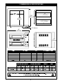
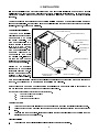
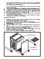
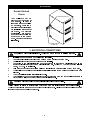
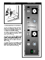
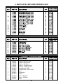
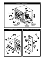
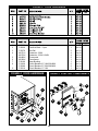
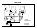
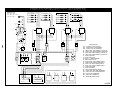
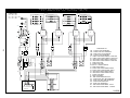
INSTALLATION AND OPERATING INSTRUCTIONS COUNTERTOP MODEL ELECTRIC PIZZA OVEN Model: ! ! EP-2-2828 Do not store or use flammable liquids or vapors in the vicinity of this or any other appliance. ! Improper installation, adjustment, alteration, service or maintenance can cause property damage, injury or death. Read the Installation, Operating and Maintenance instructions thoroughly before installing or servicing this equipment. ! For Your Safety: Warning: Initial heating of this oven may generate smoke or fumes and must be done in a well ventilated area. Overexposure to smoke or fumes may cause nausea or dizziness. This equipment has been engineered to provide you with year round dependable service when used according to the instructions in this manual and standard commercial kitchen practices. ANSI/NSF4 BAKERS PRIDE OVEN CO., INC. +1 (914) 576-0200 Phone +1 (914) 576-0605 Fax 30 Pine Street New Rochelle, NY 10801 1 Form #U4186A 5/05 (800) 431-2745 US & Canada www.bakerspride.com WebAddress [email protected] e-mail TABLE OF CONTENTS SECTION ITEM PAGE 1 Dimensions & Specifications 3 2 Installation Counter-Top Installation Floor Installation Optional Open Base Feature Double Stacked Ovens 4 4 4 5 6 3 Electrical Connections 6 4 Explanation Of Controls 7 5 Usage Recommendations 8 6 Troubleshooting 8 7 Cleaning Exterior Cleaning Interior Cleaning 9 9 9 8 Maintenance Replacement Parts Wiring Diagrams 9 9 9 9 Parts Lists & Exploded Views 10 10 Wiring Diagrams 13 11 Warranty 16 Periodic inspections by your dealer or a qualified service agent is recommended. When corresponding with the factory or your service agent regarding service problems or replacement parts, be sure to refer to the oven by the correct model number (including the prefix and suffix letters and numbers and the warranty serial number. The rating plate affixed to the oven contains this information. IMPORTANT FOR FUTURE REFERENCE Please complete this information and retain this manual for the life of the equipment. For Warranty Service and/or Parts, this information is required. Model Number Serial Number 2 Date Purchased 1. DIMENSIONS & SPECIFICATIONS 28 (711mm) 28” (711mm) 33.25” (845mm) 28 (711mm) 5.25” (133mm) 2.5” (64mm) 42” (1067mm) 29” (737mm) Volts Amperes 208-1 208-3 230-1 240-1 240-3 400-3 44 25 39 38 22 13 Interior Dimensions Single Double ! NOTE: kW Nominal Amperes 9.5 9.5 9.5 9.5 9.5 9.5 44 30/31/32 39 38 22/23/23 13/12/13 Weight Size 458 916 23.26 46.50 Each oven requires its own supply connection to mains. Ovens are shipped individually. ! 28 5.25 28 Exterior Dimensions 42 42 3 29 58 33 33 2. INSTALLATION It is the responsibility of the purchaser to insure the oven is properly installed in a manner that meets all applicable codes. In the absence of local codes refer to applicable national codes. In the case of any discrepancy between this document and any local codes it is recommended you consult your local inspector. Users are cautioned that maintenance and repairs shall be performed by authorized service agents or licensed professionals. Bakers Pride will have no obligation with respect to products that are not properly installed, adjusted, operated or maintained. Counter-top Installation 4 inch COUNTER TOP LEG (4) The oven may be installed directly on a counter or stand manufactured of nonflammable materials. The oven must be installed on a surface that is at least as large as the outer dimensions of the oven. The oven must be installed with adequate clearance to combustible and noncombustible walls. If legs are not used the oven must be sealed to the countertop with an NSF approved sealant. LEG WITH CASTER PLATE (4) CASTER WITHOUT LOCK (2) MOUNT IN REAR FLAT WASHER (16) LOCK WASHER (16) BOLT (16) LEG WITH FOOT INSERT (4) Minimum operating FLAT WASHER (12) clearances to combustible BOLT (12) surfaces is 1 inch [25 mm]. It is recommended the oven be CASTER WITH LOCK (2) BULLET FOOT INSERT (4) at least 1 inch from any MOUNT IN FRONT adjacent cooking appliance. Each oven shall be installed with respect to building construction and other equipment to permit access to the oven. Such clearance may be necessary for servicing and cleaning. Bakers Pride recommends the mounting surface for a single oven be approximately 26 inches [660 mm] from the floor so the oven decks are at a convenient working height. NOTE: Refer to illustration for all three leg configurations. A. Counter Top - Short Legs - 4 B. Floor Model - 30 C. Floor/Double Stack - 16 Counter Top Legs 1. 2. 3. Turn the oven over onto its left side so you can easily reach the bolt mounting locations in the base. Using the four corner most holes in the bottom of the oven insert and tighten the four counter top legs. Carefully turn the oven upright. Insure the two legs that touch the floor first when you raise the oven are blocked so they do not slip away. Floor Installation 1. At the floor end of each leg install the bullet foot insert or caster as required. 4 The fit of the insert to the leg is intended to be snug, you should expect to tap them lightly in place with a mallet or rubber hammer. Using your fingers screw the ends of the bullet feet into the leg clockwise until they are at their shortest length. OR Casters mount to the bottom of the caster plate with four each: 3/8-16 bolts inserted into a split ring lock washer and flat washer. 2. Turn the oven over onto its left side so you can easily reach the bolt mounting locations in the base. 3. The three holes in the top of each leg will match the bolt locations at each corner of the oven base. 4. You will need three 3/8-16 hex head bolts and three 3/8 flat washers to mount each leg. Align the leg to one of the matching bolt holes on the base and insert a bolt and washer. Install the other bolts and finger tighten into place before using a wrench to fully tighten them all. 5. Be sure to tighten all bolts for each leg. When installing casters, make sure the two casters with brakes are installed at the front of the oven. 6. Carefully stand up the oven. Insure the two legs/casters that touch the floor first when you raise the oven are blocked and chocked so they do not slip away. Optional Open Base Feature: 1. 2. 3. 4. 5. 6. 7. 8. Install bottom shelf and rack guide brackets when installing legs - while oven is on its side. Refer to leg instructions in Installation/Operation Manual. Attach two rack support brackets to base of oven with three screws each bracket. Install two legs to lower (left) side of oven.Align and attach bottom shelf to these legs with a bolt and locking nut - One each in the front and back. Attach last two legs. Attach bottom shelf to remaining two legs with two bolts and locking nuts - One each in the front and back. When the oven is stood up, before moving it to its final location, install four remaining bolts and locking nuts to the legs - Two on left side, two on right side. Tighten all. Install two rack guides. Align the bottom pegs to holes in the bottom shelf. Align top hooks to cutouts in upper support bracket. Lower into position. Align oven racks (order separately) to the shelf heights desired and slide into place. Upper Support Bracket (2) Rack Guide (2) Bottom Shelf 5 STACKING Double Stacked Ovens C5057X BRACKET (2) Your EP-2-2828 may be stacked two ovens on top of one another. In order to insure the ovens to not slide or separate, there is a stacking bracket kit required for installation at the rear of the ovens. Two brackets are installed, one at each end of the oven securing the upper oven to the bottom oven. Refer to the adjacent illustration. #10 SHEET METAL SCREW (8) 3. ELECTRICAL CONNECTIONS ! 1 2 3 4 WARNING: Risk of electrical shock. Appliance must be secured to building structure. ! Installation must be performed by a licensed electrician. A separate electrical connection to the mains must be provided for each oven. An all pole disconnect must be provided by the installer. Connection to the electrical service must be grounded in accordance with local codes. In the absence of local codes refer to the National Electric Code, ANSI/NFPA 70 or the Canadian Electric Code, CSAC22.2 as applicable. Only bare copper conductors with a minimum insulation temperature rating of 90ºC to be used. The installer must supply a properly sized strain relief bushing for the mains connection that meets all codes. The oven shall be installed using flexible conduit. The restraint cord must be securely attached to the rear of the oven and to the building structure to prevent transmitting unnecessary stress to the flexible conduit. 5 6 7 8 ! Caution: Disconnect all ovens from electrical supply before servicing. ! A wiring diagram is affixed to the inner side cover of the oven and included in the rear of this booklet. The input connection is accessed be removing the right side cover. Field connections are located at the lower rear corner of the control compartment. 6 HOOK UP CONTROL PANEL L1 L2 L3 4. EXPLAINATION OF CONTROLS The oven has a main power switch at the bottom portion of the control panel. This switch must be on for the oven to operate. When switched to the ON position the lamps in each cavity light. Each cavity has separate temperature controls. The thermostat dial may be adjusted from 200°F (100ºC) to 700°F (370ºC). Each cavity has top and bottom infinite control switches. Turning the dial of the infinite control to 0 will turn off the heat for that portion of the oven cavity. The proportion of heat decreases as the dial is adjusted from a maximum of 10 to a minimum of 1. By changing the adjustment of the infinite control switches an operator can vary the heat in the cavity for more or less top heat, more or less bottom heat or equal heat top and bottom. 7 Each cavity has a timer that may be used when cooking product. The timer DOES NOT control the oven. To set a cook time turn the dial clock wise to the desired setting. The timer will count down until the time expires. A buzzer will sound continuously until the dial is turned to the OFF position slightly to the left of 0. 5. USAGE RECOMMENDATIONS 1. 2. 3. 4. 5. 6. 7. 8. 9. 10. 11. 12. 13. 14. Pre-heat the oven thoroughly before use. Allow one hour and fifteen minutes for pre-heat. Pre-heat ovens @ 75°F (24°C) BELOW desired cook/bake temperature. Do not move baking location in the middle of a bake, but spinning is okay. Keep decks clean of flour, cheese, etc using a deck/scraper brush. During idle periods, reduce heat by 75°F (24°C). Minimize water content of products for faster cook/bake times. For larger & thick products, reduce temperature & increase bake/cook time. Cooking times and temperatures will vary depending upon such factors as size of the load, temperature, mixture of products (particularly moisture) and density of products. Keep a record of the times, temperature and load sizes you establish for various products. Once you have determined these, they will be similar for succeeding loads. When practical, start cooking the lowest temperature product first and gradually work up to the higher temperatures. When loading the oven, work as quickly as possible to prevent loss of heat. Oven will continue to heat even though the timer goes off. Product should be removed from the oven as soon as possible to avoid overcooking. When baking, weigh or measure the product in each pan to assure even cooking. Only bread and pizza may be placed directly on a stone baking hearth. 6. Trouble Shooting There are no user serviceable components under the covers. Contact your service agent. PROBLEM CAUSE TO INVESTIGATE No power on - lights do not come on, oven does not heat-up No power to oven - check supply voltage Circuit breaker tripped - reset and check oven for fault condition High temperature thermostat tripped - reset and check oven for fault condition No cavity heat - oven lights Circuit breaker tripped - reset and check oven for fault condition come on, elements do not heat up Thermostat faulty - replace Contactor faulty - replace Uneven heat Bad element - replace Infinite control thermostat faulty - replace Oven won't reach temperature Bad element - replace Thermostat faulty - replace 8 7. CLEANING ! Caution: Disconnect all ovens from electrical supply before servicing. ! When the oven is new, operate it for at least one hour at a setting of at least 500°F (250ºC). Due to normal manufacturing processes, a small amount of steam and/or smoke will exit the oven from moisture and oils on the oven components. Shut off and allow the oven to cool. After cooling wipe down the interior of the oven with a clean damp cloth. Brushing of the baking hearth is recommended. Exterior Cleaning It is recommended that a regular cleaning schedule be maintained to keep your oven operating and looking its best. Spills should be cleaned immediately. The oven should always be allowed to cool sufficiently before cleaning. Exterior surfaces should be wiped with a soft cloth and mild detergent. Stubborn stains may be cleaned with a light weight, non-metallic cleaning pad. Apply only light pressure and rub in the direction of the surface grain. The control panel surface is easily cleaned with a soft cloth and mild detergent. Do not use abrasives, solvent cleaners or metallic scouring pads on the control panel. They may scratch or damage the label surface. Never spray steam or water directly onto or into the oven. This could adversely affect the ceramic cooking hearth and/or electrical components. Interior Cleaning Internal metallic surfaces should be allowed to cool before cleaning. Wipe interior surfaces with a wet cloth or light weight scouring pad. Food particles or spills that accumulate on the baking hearth may be brushed off with a normal oven brush. Stubborn spills should be heated to a maximum temperature for approximately one hour to burn the spill so it will crumble and easily brush out afterwards. Do not use oven cleaners, caustic solutions or mechanical means that may damage the interior of your oven. 8. MAINTENANCE Users are cautioned that maintenance and adjustments should only be performed by authorized service agents using Baker's Pride replacement parts. Minor periodic maintenance to your oven should provide many years of useful service to you. Any time the unit is serviced it is recommended all components be checked and their performance verified. At least once each year your oven should be inspected by a qualified service provider to insure your oven is operating at its peak performance. Replacement Parts Enclosed in this booklet are diagrams of likely replacement parts that may be required for normal maintenance. Specifications are subject to change without notice. Be sure to verify the current specification with your qualified service provider or Bakers Pride before ordering replacement parts. Wiring Diagrams The current wiring diagram at the date of your oven's manufacture was affixed to the unit for reference. Copies of the proper wiring diagrams effective on the date this booklet is printed are enclosed. Specifications are subject to change without notice. If there is any uncertainty or discrepancy between the wiring diagram and your oven refer to Bakers Pride Technical Service for clarification. 9 9. PARTS LISTS & EXPLODED VIEWS EP-2-2828 FIGURE 1 9 U1043A MAIN BODY Name Plate 1 Apr 04 1 1 1 1 1 4 4 4 2 1 2 2 2 Apr 04 Sep 04 Apr 04 Sep 04 Sep 04 Sep 04 Apr 04 Apr 04 Apr 04 Apr 04 Sep 04 Sep 04 Sep 04 FIGURE 2 DOORS FIGURE 3 CONTROL PANEL 1 2 3 4 5 6 7 8 C5029X C5058X U1382X U1395X U1383X M1367X M1368X S1306X M1481X M1352X M1382X M1384X S1311S Control Panel w/o Timer Control Panel w/Timer Overlay - No Timer Overlay - 15 Minute Timer Overlay - 60 Minute Timer Infinite Switch - 208V Infinite Switch - 230V & 240V Knob Thermostat Switch Timer - 60 Minute Timer - 15 Minute Knob 10 FIGURE 1 MAIN BODY 3 99 4 DOORS SEE FIG 2 2 2 5 5 1 1 6 6 88 7 7 CONTROL PANEL SEE FIG 3 DOOR HARDWARE SEE FIG 4 ELECTRICAL COMPONENTS SEE FIG 5 FIGURE 3 CONTROL PANEL FIGURE 2 DOORS 1 22 1 5 3 44 3 1 2 4 8 7 6 6 5 5 7 8 6 11 FIGURE 4 DOOR HARDWARE FIGURE 5 ELECTRIC COMPONENTS C5025X P1003X P1207X M1371X M1372X M1482X M1360X P1018X P1192X P1208X P1201X 1 2 3 4 5 6 7 8 9 1 1 2 4 4 2 1 1 2 2 1 Component Bracket Terminal Block - 3 pos Din Rail Contactor - 208V Contactor - 230V & 240V Thermostat Transformer Snap Bushing Circuit Breaker-3 P 10A 230/400V Circuit Breaker-3 P 25A 208/240V Circuit Breaker-1 P 10A FIGURE 4 DOOR HARDWARE Apr 04 Apr 04 Apr 04 Sep 04 Apr 04 Apr 04 Apr 04 Apr 04 Apr 04 Sep 04 Apr 04 FIGURE 5 ELECTRIC COMPONENTS 5 7 8 6 5 10 2 3 4 3 5 8 1 9 9 7 1 4 2 6 6 12 3 10. WIRING DIAGRAMS WIRING DIAGRAM EP-2-2828 230/400, 50HZ ELEMENT LOAD: P1 = R6 + R7 P2 = R2 + R3 + R4 P3 = R1 + R5 LOWER OVEN R 1 750 WATTS 67 72 R 2 500 WATTS 63 73 62 74 R 3 500 WATTS R 4 500 WATTS 66 70 84 69 85 S1 P2 S2 T1 86 YEL BLK 67 68 69 T3 T4 T1 A2 13 39 H1 L1 S2 14 19 17 17 15 72 T4 A2 L1 L2 L3 L4 L1 L2 L3 L4 55 57 10 54 56 58 12 49 47 48 54 50 56 52 58 51 21 S3 30 43 H2 H1 L2 L1 23 25 5 1 TB1 L1 L2 L3 THREE PHASE N E TB1 2 N OPTIONAL SINGLE PHASE H1 L2 L1 27 53 E 55 57 23 29 TH 4 CB3 12 1 2 3 7 11 31 1 2 10 34 S5 H2 COMPONENT LIST L2 20 20 3 11 L1 L2 L3 45 1 2 9 32 H2 31 18 9 11 7 S4 29 18 TH 3 CB2 5 34 53 16 3 A2 K4 32 8 27 1 T4 L4 16 2 A1 92 L3 4 9 45 91 T3 52 TB 2 5 A2 K3 T2 50 8 1 T1 L2 6 7 89 T4 L1 19 3 88 T3 48 L1 13 87 6 L2 13 A1 43 81 T2 L4 2 4 T1 51 41 TH 2 LOWER ELEMENTS L3 H1 15 89 81 49 28 CB1 TH 1 R 17 750 WATTS L2 22 S1 94 90 L1 25 33 82 30 H2 14 93 47 22 21 71 T3 K2 A1 41 T2 28 BLU 33 61 T2 K1 A1 39 ORG 83 UPPER ELEMENTS TR 1 P1 91 R 16 750 WATTS R 13 500 WATTS UPPER ELEMENTS TERMINATE WHT & RED 92 R 14 500 WATTS LOWER ELEMENTS 61 R 15 750 WATTS 87 R 12 500 WATTS R 7 750 WATTS 65 L2 88 71 R 6 750 WATTS 64 L1 UPPER OVEN R 11 750 WATTS R 5 750 WATTS 68 CB1 - CONTROL CIRCUIT BREAKER CB2 - LOWER OVEN CIRCUIT BREAKER CB3 - UPPER OVEN CIRCUIT BREAKER K1 - LOWER OVEN UPPER ELEMENT CONTACTOR K2 - LOWER OVEN LOWER ELEMENT CONTACTOR K3 - UPPER OVEN UPPER ELEMENT CONTACTOR K4 - UPPER OVEN LOWER ELEMENT CONTACTOR L1 - UPPER OVEN LAMP L2 - LOWER OVEN LAMP R1 THRU R17 - HEATER ELEMENTS S1 - MAIN POWER SWITCH S2 - LOWER OVEN UPPER ELEMENT SWITCH S3 - LOWER OVEN LOWER ELEMENT SWITCH S4 - UPPER OVEN UPPER ELEMENT SWITCH S5 - UPPER OVEN LOWER ELEMENT SWITCH TB1 - MAIN POWER TERMINAL BLOCK TB2 - NUETRAL DISTRIBUTION TH1 - LOWER OVEN HIGH LIMIT THERMOSTAT TH2 - UPPER OVEN HIGH LIMIT THERMOSTAT TH3 - LOWER OVEN THERMOSTAT TH4 - UPPER OVEN THERMOSTAT TR1 - STEP DOWN TRANSFORMER U4187A WIRING DIAGRAM EP-2-2828 208/240, 60HZ (DOMESTIC) ELEMENT LOAD: Z-X = R6 + R7 X-Y = R2 + R3 + R4 Y-Z = R1 + R5 LOWER OVEN R 1 750 WATTS 67 72 R 2 500 WATTS 63 73 62 74 R 3 500 WATTS L2 R 4 500 WATTS 66 70 84 69 85 92 91 R 16 750 WATTS 83 93 82 94 90 R 13 500 WATTS R 17 750 WATTS 89 R 14 500 WATTS LOWER ELEMENTS 61 87 R 12 500 WATTS R 7 750 WATTS 65 R 15 750 WATTS 88 71 R 6 750 WATTS 64 L1 UPPER OVEN R 11 750 WATTS R 5 750 WATTS 68 86 LOWER ELEMENTS 81 UPPER ELEMENTS UPPER ELEMENTS RED 208V ORG 240V 64 61 68 T1 T2 T3 73 72 69 T1 T2 T3 84 81 88 T1 T2 T3 93 92 89 T1 T2 T3 TR 1 P1 S1 P2 S2 YEL TERMINATE WHITE AND UNUSED BLK K1 A1 39 T4 A2 A2 L1 L2 L3 47 49 51 L4 35 K3 A1 43 T4 A2 45 30 28 BLU 37 K2 A1 41 T4 L1 L2 L3 48 50 52 T4 K4 A1 A2 32 L4 L1 L2 L3 53 55 57 34 L4 48 54 50 56 52 58 L1 L2 L3 54 56 58 L4 26 T2 24 35 33 39 28 41 30 43 32 45 34 H1 H2 H1 H2 H1 H2 H1 H2 L2 L1 14 L1 S2 L1 L2 24 S3 L1 L2 27 25 16 14 S4 29 18 16 14 33 19 17 17 15 47 15 49 21 51 22 23 S1 TH 1 4 13 13 53 1 5 9 55 23 57 29 31 1 2 TH 3 CB2 TH 2 27 1 2 CB1 25 TH 4 CB3 7 3 4 11 19 OPTIONAL SINGLE PHASE ELMENT WIRING 5 1 9 1 3 7 11 X Y Z TB1 THREE PHASE 9 3 E X 67 68 73 64 61 72 T1 T2 T3 T1 T4 69 T2 T3 87 88 84 81 T1 T4 T2 T3 93 92 T1 T4 89 T2 T3 T4 11 Y Z TB1 OPTIONAL SINGLE PHASE E K1 A1 L1 L2 L3 A2 L4 K2 A1 L1 L2 L3 A2 L4 L2 20 20 18 T1 22 21 S5 31 K3 A1 L1 L2 L3 A2 L4 K4 A1 L1 L2 L3 COMPONENT LIST CB1 - CONTROL CIRCUIT BREAKER CB2 - LOWER OVEN CIRCUIT BREAKER CB3 - UPPER OVEN CIRCUIT BREAKER K1 - LOWER OVEN UPPER ELEMENT CONTACTOR K2 - LOWER OVEN LOWER ELEMENT CONTACTOR K3 - UPPER OVEN UPPER ELEMENT CONTACTOR K4 - UPPER OVEN LOWER ELEMENT CONTACTOR L1 - UPPER OVEN LAMP L2 - LOWER OVEN LAMP R1 THRU R17 - HEATER ELEMENTS S1 - MAIN POWER SWITCH S2 - LOWER OVEN UPPER ELEMENT SWITCH S3 - LOWER OVEN LOWER ELEMENT SWITCH S4 - UPPER OVEN UPPER ELEMENT SWITCH S5 - UPPER OVEN LOWER ELEMENT SWITCH T1 - LOWER OVEN TIMER T2 - UPPER OVEN TIMER TB1 - MAIN POWER TERMINAL BLOCK TH1 - LOWER OVEN HIGH LIMIT THERMOSTAT TH2 - UPPER OVEN HIGH LIMIT THERMOSTAT TH3 - LOWER OVEN THERMOSTAT TH4 - UPPER OVEN THERMOSTAT TR1 - STEP DOWN TRANSFORMER A2 L4 U4188A WIRING DIAGRAM EP-2-2828 480V, 60HZ, 3PH ELEMENT LOAD: Z-X = R6 + R7 X-Y = R2 + R3 + R4 Y-Z = R1 + R5 LOWER OVEN R 1 750 WATTS 67 72 63 73 62 74 R 3 500 WATTS 70 84 69 85 R 4 500 WATTS 66 86 91 R 16 750 WATTS 83 93 82 94 90 R 17 750 WATTS R 14 500 WATTS LOWER ELEMENTS 61 92 R 13 500 WATTS R 7 750 WATTS 65 R 15 750 WATTS 87 R 12 500 WATTS R 6 750 WATTS 64 L2 88 71 R 2 500 WATTS L1 UPPER OVEN R 11 750 WATTS R 5 750 WATTS 68 89 LOWER ELEMENTS 81 UPPER ELEMENTS UPPER ELEMENTS ORG 64 61 68 T1 T2 T3 73 72 69 T1 T2 T3 84 81 88 T1 T2 T3 93 92 89 T1 T2 T3 TR 1 P1 S1 P2 S2 YEL TERMINATE WHITE AND RED BLK K1 A1 39 T4 A2 A2 L1 L2 L3 47 49 51 L4 35 K3 A1 43 T4 A2 30 28 BLU 37 K2 A1 41 T4 L1 L2 L3 48 50 52 45 T4 K4 A1 A2 32 L4 L1 L2 L3 53 55 57 34 L4 48 54 50 56 52 58 L1 L2 L3 54 56 58 L4 26 T2 24 35 33 15 39 28 41 30 43 32 45 34 H1 H2 H1 H2 H1 H2 H1 H2 L2 L1 L1 S2 L1 L2 24 S3 L1 L2 27 25 14 16 S4 29 18 16 18 20 14 33 19 17 17 15 47 15 49 21 51 22 23 S1 TH 1 4 13 35 1 5 9 37 TR 2 13 5 X1 H1 35 9 7 11 X Y Z E X2 H2 X3 H3 X4 H4 TB1 THREE PHASE 37 23 36 7 11 31 29 1 TH 4 3 36 CB4 3 57 CB3 19 1 55 2 TH 3 CB2 TH 2 53 1 2 CB1 27 25 L2 20 T1 22 21 S5 31 COMPONENT LIST CB1 - CONTROL CIRCUIT BREAKER CB2 - LOWER OVEN CIRCUIT BREAKER CB3 - UPPER OVEN CIRCUIT BREAKER CB4 - CONTROL CIRCUIT BREAKER K1 - LOWER OVEN UPPER ELEMENT CONTACTOR K2 - LOWER OVEN LOWER ELEMENT CONTACTOR K3 - UPPER OVEN UPPER ELEMENT CONTACTOR K4 - UPPER OVEN LOWER ELEMENT CONTACTOR L1 - UPPER OVEN LAMP L2 - LOWER OVEN LAMP R1 THRU R17 - HEATER ELEMENTS S1 - MAIN POWER SWITCH S2 - LOWER OVEN UPPER ELEMENT SWITCH S3 - LOWER OVEN LOWER ELEMENT SWITCH S4 - UPPER OVEN UPPER ELEMENT SWITCH S5 - UPPER OVEN LOWER ELEMENT SWITCH T1 - LOWER OVEN TIMER T2 - UPPER OVEN TIMER TB1 - MAIN POWER TERMINAL BLOCK TH1 - LOWER OVEN HIGH LIMIT THERMOSTAT TH2 - UPPER OVEN HIGH LIMIT THERMOSTAT TH3 - LOWER OVEN THERMOSTAT TH4 - UPPER OVEN THERMOSTAT TR1 - STEP DOWN TRANSFORMER - LIGHTS TR2 - STEP DOWN TRANSFORMER - CONTROL U4189A BAKERS PRIDE LIMITED WARRANTY 30 Pine Street New Rochelle, New York 10801 914 / 576 - 0200 US & Canada: 1 - 800 - 431 - 2745 fax 914 / 576 - 0605 WHAT IS COVERED This warranty covers defects in material and workmanship under normal use, and applies only to the original purchaser providing that: The equipment has not been accidentally or intentionally damaged, altered or misused; ! The equipment is properly installed, adjusted, operated and maintained in accordance with National and local ! codes, and in accordance with the installation instruction provided with the product; The serial number rating plate affixed to the equipment has not been defaced or removed. ! WHO IS COVERED This warranty is extended to the original purchaser and applies only to equipment purchased for use in the U.S.A. COVERAGE PERIOD Cyclone Convection Ovens: BCO Models: One (1) Year limited parts and labor; (1) Year limited door warranty. GDCO Models: Two (2) Year limited parts and labor; (2) Year limited door warranty. CO11 Models: Two (2) Year limited parts and labor; (5) Year limited door warranty. All Other Products: One (1) Year limited parts and labor. Warranty period begins the date of dealer invoice to customer or ninety (90) days after shipment date from BAKERS PRIDE - whichever comes first. WARRANTY COVERAGE This warranty covers on-site labor, parts and reasonable travel time and travel expenses of the authorized service representative up to (100) miles, round trip, and (2) hours travel time. The purchaser, however, shall be responsible for all expenses related to travel, including time, mileage and shipping expenses on smaller counter models that may be carried into a Factory Authorized Service Center, including the following models: PX-14, PX-16, P18, P22S, P24S, PD-4, PDC, WS Series and BK-18. EXCEPTIONS All removable parts in BAKERS PRIDE Char-broilers, including but not limited to: Burners, Grates, Radiants, Stones and Valves, are covered for a period of SIX MONTHS. All Ceramic Baking Decks are covered for a period of THREE MONTHS. The installation of these replacement decks is the responsibility of the purchaser. The extended Cyclone door warranty years 3 through 5 is a parts only warranty and does not include labor, travel, milage or any other charges. EXCLUSIONS Failures caused by erratic voltages or gas supplies, Unauthorized repair by anyone other than a BAKERS PRIDE Factory Authorized Service Center, Damage in shipment, Alteration, misuse or improper installation, Thermostats and safety valves with broken capillary tubes, Accessories spatulas, forks, steak turners, grate lifters, oven brushes, scrapers, peels, etc., Freight other than normal UPS charges, Ordinary wear and tear. Negligence or acts of God, Thermostat calibrations after (30) days from equipment installation date, Air and Gas adjustments, Light bulbs, Glass doors and door adjustments, Fuses, Char-broiler work decks and cutting boards, Tightening of conveyor chains, Adjustments to burner flames and cleaning of pilot burners, Tightening of screws or fasteners, INSTALLATION Leveling and installation of decks, as well as proper installation and check out of all new equipment per appropriate installation and use materials is the responsibility of the dealer or installer, not the manufacturer. REPLACEMENT PARTS BAKERS PRIDE genuine Factory OEM parts receive a (90) day materials warranty effective from the date of installation by a BAKERS PRIDE Factory Authorized Service Center. This Warranty is in lieu of all other warranties, expressed or implied, and all other obligations or liabilities on the manufacturers part. BAKERS PRIDE shall in no event be liable for any special, indirect or consequential damages, or in any event for damages in excess of the purchase price of the unit. The repair or replacement of proven defective parts shall constitute a fulfillment of all obligations under the terms of this warranty. Form #U4177A 3/04 16


![ハイブリッド記録計 [形式:SR186Aシリーズ] 取扱説明書の補足説明](http://vs1.manualzilla.com/store/data/006711725_2-e1476d5c686a5d05489fa0db7e15f858-150x150.png)
