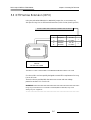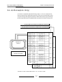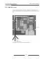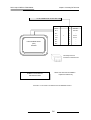
1
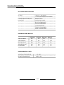
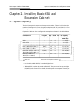
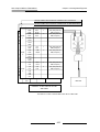
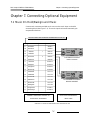
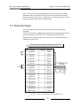
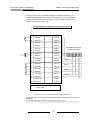
DCS Compact II
INSTALLATION MANUAL
SAMSUNG TELECOMS
Publication Information
Samsung Telecoms the right without prior notice to revise infomation in this
publication for any reason.
Samsung Telecoms also reserve the right without prior notice to make
chages in design or components of equipment as engineering and
manufacturing may warrant.
Copyright 1998
Samsung Telecoms
All rights reserved. No part of this manual may be reproduced in any form or
by any mean - graphic, electronic or mechanical, including recording, taping,
photocopy or information retrieval system - without express written
permission of the publisher of this material.
SEPTEMBER/1998
Part: 12935
Issue: 2
DCS Compact II INSTALLATION MANUAL
TABLE OF CONTENTS
Chapter 1. Site Requirements ........................................................ 1-1
Chapter 2. Installing Basic KSU and Expansion Cabinet .................... 2-1~2-12
2.1
2.2
2.3
2.4
2.5
2.6
2.7
2.8
System Capacity ............................................................................................ 2-1
Unpacking and Inspection ............................................................................ 2-2
Basic KSU Installation .................................................................................. 2-3
Expansion Cabinet Installation .................................................................... 2-4
RGU(Ring Generator Unit) Installation ...................................................... 2-8
Grounding ...................................................................................................... 2-9
MDF Cabling ................................................................................................. 2-9
Battery For Power Failure .......................................................................... 2-10
Chapter 3. Installing Printed Circuit Cards ............................. 3-1~3-8
3.1
3.2
3.3
3.4
3.5
3.6
3.7
3.8
MEM Card ..................................................................................................... 3-2
3TRK Card ...................................................................................................... 3-2
6 TRK Card ..................................................................................................... 3-3
8SLI Card ........................................................................................................ 3-3
2 SLI Card ....................................................................................................... 3-4
6MWSLI Card ................................................................................................ 3-4
8DLI Card ....................................................................................................... 3-5
MISC Cards .................................................................................................... 3-5
3.8.1 MISC 1 Card(Without AA) ................................................................. 3-5
3.8.2 MISC 2 Card(With AA) ....................................................................... 3-5
3.9 PRI Card ......................................................................................................... 3-6
3.10 4BRI (4S0T0) Card ...................................................................................... 3-7
3.11 2BRI (2S0T0) Card ...................................................................................... 3-7
3.12 PLL Card ...................................................................................................... 3-7
3.13 MODEM Card ............................................................................................. 3-8
3.14 AC 15 Card(U.K. Only) ............................................................................... 3-8
Chapter 4. Power Up Procedures .......................................... 4-1~4-2
4.1
4.2
4.3
4.4
Connect Power to The System ..................................................................... 4-1
MEM Card Indications ................................................................................. 4-2
PCB Verification ............................................................................................ 4-2
Default Trunk and Station Numbering ....................................................... 4-2
i
DCS Compact II INSTALLATION MANUAL
Chapter 5. Connecting PSTN Circuits ...................................... 5-1~5-8
5.1
5.2
5.3
5.4
5.5
5.6
Safety Precautions ......................................................................................... 5-1
Loop Start Lines ............................................................................................. 5-2
Off Premise Extension (OPX) ...................................................................... 5-3
AC 15 Lines(U.K. Only) ................................................................................ 5-4
ISDN PRI Lines ............................................................................................. 5-5
ISDN BRI Lines ............................................................................................. 5-7
Chapter 6. Connecting Station Equipment .......................... 6-1~6-12
6.1
6.2
6.3
6.4
6.5
6.6
Safety Precautions ......................................................................................... 6-1
DCS Compact II Keyset ................................................................................ 6-2
Add-On Module ............................................................................................. 6-4
Single Line Telephone .................................................................................. 6-6
Door Phone and Door Lock Release ........................................................... 6-8
ISDN Terminal Equipment (S0 Bus) ........................................................ 6-10
Chapter 7. Connecting Optional Equipment ........................ 7-1~7-10
7.1
7.2
7.3
7.4
7.5
7.6
7.7
7.8
7.9
Music On Hold/Background Music ........................................................... 7-1
External Paging ............................................................................................. 7-2
Common Bell ................................................................................................. 7-4
Ring Over Page .............................................................................................. 7-5
Station Message Detail Recording (SMDR) ............................................... 7-6
PC Programming ........................................................................................... 7-7
Remote Programming ................................................................................... 7-7
Power Failure Transfer (PFT) ..................................................................... 7-8
Voice Mail/Auto Attendant .......................................................................... 7-8
Chapter 8. Installing Keyset Daughter Boards(KDBs) ............. 8-1~8-6
8.1 KDB–SLI ........................................................................................................ 8-1
8.2 Connecting to the KDB ................................................................................ 8-4
8.3 Wall-Mounting a Keyset ............................................................................... 8-6
Chapter 9. Changing Software ...................................................... 9-1
ii
Chapter 1
Site Requirements
DCS Compact II INSTALLATION MANUAL
Chapter 1. Site Requirements
Chapter 1. Site Requirements
When planning the installation of the DCS Compact II, choose a site that meets
the following requirements:
• Select a location for the key service unit (KSU) that has enough space for easy
installation and adequate lighting.
• Select a location that minimises cable lengths. See the Cable Requirements
table below.
• The equipment should not be exposed to direct sunlight, corrosive fumes,
dust, constant vibration or strong magnetic fields such as those generated by
motors and copy machines.
• A direct commercial AC power outlet is required. Do not use extension cords.
Preferably, a dedicated circuit should be used to minimise the risk of other
electrical equipment being connected that could adversely affect system
operation.
• Ensure that all wires and cables going to and coming from the KSU are
properly routed. Do not cross fluorescent lights or run parallel with AC wires.
• Allow at least 150mm clearance on both sides and 150mm clearance on top of
the KSU to ensure proper ventilation.
• Do not install within a 2-mile radius of broadcasting antenna or in close
proximity to a fire sprinkler head or other sources of water.
Meeting these requirements will help to ensure proper performance and greater
life expectancy of the system.
CABLE REQUIREMENTS
EQUIPMENT
CABLE
AWG
MAX FEET
MAX METRES
DIGITAL KEYSETS
1PR. TWISTED
24
1300
400
ADD-ON MODULES
1PR. TWISTED
24
1300
400
SINGLE LINE STATION
1PR. TWISTED
24
3000
1 KM
DOOR PHONE
2PR. TWISTED
24
330*
100
* This is the maximum distance a door phone can be from the door phone interface
module (DPIM). The DPIM can be a maximum of 274 cable metres from the KSU.
1-1
DCS Compact II INSTALLATION MANUAL
ELECTRICAL SPECIFICATIONS
AC INPUT
220VAC +/- 20%, 48~60Hz
or Free Input Voltage for some countries.
POWER CONSUMPTION(MAX)
100 WATTS MAX
DC OUTPUT
FUSE RATING 2.0 AMP
+5 VOLTS 2.5 AMPS MAX
-5 VOLTS 0.5 AMPS MAX
(on the Motherboard)
-55 VOLTS 1.2 AMPS MAX
-54 VOLTS 0.4 AMPS MAX
DIMENSIONS AND WEIGHTS
Height(mm)
Width(mm) Depth(mm) Weight(kg)
SINGLE CABINET
464
365
148
7.5
TWO CABINETS
464
467
418
12.5
DIGITAL KEYSET
108
216
229
1.2
ADD-ON MODULE
108
108
229
0.5
DOOR PHONE
127
99
32
0.2
ENVIRONMENTAL LIMITS
OPERATING TEMPERATURE
STORAGE TEMPERATURE
0ºC - 40ºC
-10.5ºC - 70ºC
1-2
Chapter 2
Installing Basic KSU and Expansion
Cabinet
DCS Compact II INSTALLATION MANUAL
Chapter 2. Installing Basic KSU and Expansion Cabinet
Chapter 2. Installing Basic KSU and
Expansion Cabinet
2.1 System Capacity
The DCS Compact II system can have up to 40 stations. There is no limit to the
number of analogue C.O. lines, single line telephones(SLTs) and ISDN C.O. lines
if enough slots are available. A PRI card is inserted into the PRI slot in the
Expansion Cabinet. Some configuration examples are shown in the table below.
Combination of
Boards
Loop Start Key KDB-D SLI Max Capacity
Trunk(BRI I/F) sets /KDB-S
(Including
KDB line)
Basic
0
8
8
0 * 8 (16)
Basic+3TRK
3
8
8
3 * 8 (16)
Basic+4BRI(4S0T0)
4(8CH)
8
8
8 * 8 (16)
Basic +4BRI(4S0T0)+8DLI * 2
4(8CH)
24
8
8 * 24 (32)
Basic +3TRK * 2 + 8DLI
6
16
8
6 * 16 (24)
Basic(4BRI (4S0T0) + 8DLI * 2)
8(16CH)
40
8
16 * 40(48)
+EXP(4BRI (4S0T0)+8DLI * 2)
Basic(6TRK+8DLI* 2)
12
32
8
12 * 32(40)
+EXP(3TRK *2 +8DLI)
Basic KSU
Basic KSU Plus Expansion Cabinet
• In this table, 4BRI (4S0T0) is used as digital trunk.
• 4BRI (4S0T0) card can be used as ISDN NT. Each port can have up to eight
ISDN TEs(see Chapter 5 for details), but the power consumption of each port
is limited to 4 watts.
2-1
DCS Compact II INSTALLATION MANUAL
Chapter 2. Installing Basic KSU and Expansion Cabinet
2.2 Unpacking and Inspection
After unpacking the KSU, inspect for signs of physical damage. If any damage is
detected, do not attempt to install. Contact your dealer for advice.
Check to see that Basic KSU carton includes the following items.
• Basic Key Service Unit (KSU)
• PWR input cable
• Wall-mount kit
• Spare Fuse
• MEM Card
• Cores (for EMI Suppression)
• Battery connection cable
• Cable tie and Screws
Check to see that Expansion Cabinet carton includes the following items.
• Expansion Cabinet
• Wall-mount kit
• Flat connection cable
• F-GND connection cable
• Ring connection cable
• Core(for EMI Suppression)
• Screws
2-2
DCS Compact II INSTALLATION MANUAL
Chapter 2. Installing Basic KSU and Expansion Cabinet
2.3 Basic KSU Installation
The Basic KSU, which is to be accommodated in the metal cabinet, can be wall
mounted or floor mounted. If wall mounted, the KSU should be mounted on a
plywood backboard at least 15mm thick. Attach the two mounting screws to the
backboard. Hang the KSU on the two screws by its mounting holes and secure it
to the backboard with the remaining two screws. (See Figure 2–1)
<FIGURE 2-1> BASIC KSU(KEY SERVICE UNIT)
2-3
DCS Compact II INSTALLATION MANUAL
Chapter 2. Installing Basic KSU and Expansion Cabinet
2.4 Expansion Cabinet Installation
Expansion Cabinet is attached to Basic KSU using the following procedure.
a) Switch OFF the power and remove the covers of both Basic KSU and
Expansion Cabinet.
b) Using an appropriate tool, carefully remove the two blanking plates on the
right side of Basic KSU for connection route.
A is for MDF cable and B is for signal and power cable. (See Figure 2-2)
A
B
<FIGURE 2-2> RIGHT SIDE VIEW OF BASIC KSU
2-4
DCS Compact II INSTALLATION MANUAL
Chapter 2. Installing Basic KSU and Expansion Cabinet
c) Move Expansion Cabinet to Basic KSU and attach it via groove.
(See Figure 2-3)
<FIGURE 2-3> CONNECTING BASIC KSU AND EXPANSION CABINET
2-5
DCS Compact II INSTALLATION MANUAL
Chapter 2. Installing Basic KSU and Expansion Cabinet
d) Attach Expansion Cabinet to the backboard using the screws provided. (See
Figure 2-4)
Mounting
Hole
<FIGURE 2-4> MOUNTING EXPANSION CABINET ON BACKBOARD
e) Join Expansion Cabinet to Basic KSU with the provided screws.
f) Connect Expansion Cabinet to the Basic KSU via a 64-pin flat cable, two 2-wire
power connections and a F-GND connection.(See Figure 2-4)
g) Insert new optional card.
2-6
DCS Compact II INSTALLATION MANUAL
Chapter 2. Installing Basic KSU and Expansion Cabinet
h) Connect MDF cable through appropriate path. (See Figure 2-5 & 2-6)
<FIGURE 2-5> BOTTOM OF BASIC KSU
P11 P7
<FIGURE 2-6> CABLING FOR MDF
2-7
DCS Compact II INSTALLATION MANUAL
Chapter 2. Installing Basic KSU and Expansion Cabinet
2.5 RGU(Ring Generator Unit) Installation
Secure the RGU in the Basic KSU with the screws supplied. Connect the RGU
cable assembly (4 pin) to connector P11 on the motherboard. (See Figure 2-7)
<FIGURE 2-7> INSTALLING RGU
2-8
DCS Compact II INSTALLATION MANUAL
Chapter 2. Installing Basic KSU and Expansion Cabinet
2.6 Grounding
DCS Compact II comes equipped ready to use with a third wire AC ground
provided through the power cord. This third ground will be adequate for most
applications. However, if it is suspected that there is a problem with the ground
provided at AC outlet or local codes require a solid earth ground to be connected
to the KSU, the existing third wire ground must be disconnected before power is
applied. The existing third wire ground is disconnected by removing the holding
screw and tapping and storing the wire. After this wire has been disconnected,
the grounding lug on the PSU(Power Supply Unit) must be connected to a
ground rod or metal cold water pipe using #10 AWG solid copper wire.
Failure to provide an adequate ground may cause unpredictable operation or even
circuit card failure.
WARNING
Unplug the power cord from the AC outlet before attempting to connect the ground.
Hazardous voltage may cause death or injury. Observe extreme caution when working
with AC power.
2.7 MDF Cabling
All connections to the DCS Compact II system are made by way of a customerprovided main distribution frame (MDF). The KSU and expansion kit are each
connected to the MDF using a 25 pair female amphenol-type cable . These cables
can be routed into the KSU cabinet from below. (See Figure 2-5 & 2-6)
Label each cable to correspond with the connector number. Label each 66
terminating block with the same connector number with which the cable is
labelled.
Use one pair twisted wire to cross-connect stations or lines to their associated
port.
2-9
DCS Compact II INSTALLATION MANUAL
Chapter 2. Installing Basic KSU and Expansion Cabinet
2.8 Battery for Power Failure
Battery Selection
You can continue to use the DCS Compact II system during a power failure if you
have installed an appropriate battery. If you use a battery whose capacity is too
large or too small, however, the system may not operate correctly (see
specification below). Use the battery connection cable supplied with the system.
Install Procedure
First, pick out the cable through the MDF cable path. Then connect the cable to
the battery RED to positive(+) and BLACK to negative(-). Next, connect the
housing connector to the head pin in the power supply. (See Figure 2-8)
<FIGURE 2-8> CABLING FOR BATTERY CONNECTION
2-10
DCS Compact II INSTALLATION MANUAL
Chapter 2. Installing Basic KSU and Expansion Cabinet
Recommended Battery Specification
Minimum Load Current (A)
Maximum Load Current (A)
Nominal Load Current (A)
Nominal Output Voltage (V)
Charge
0
0.4
0.1
-54
Discharge
0.05
1.2
0.6
-49
• Over discharge protection voltage: -42 +/- 1V
• Maximum Keyset current consumption : 30mA
CAUTION
Switch off the power before connecting the power supply to the battery.
2-11
DCS Compact II INSTALLATION MANUAL
(This page is blank.)
2-12
Chapter 3
Installing Printed Circuit Cards
DCS Compact II INSTALLATION MANUAL
Chapter 3. Installing Printed Circuit Cards
Chapter 3. Installing Printed Circuit Cards
Unpack and inspect each card before installing. Check for signs of physical
damage. If any damage is detected, do not attempt to install. Contact your dealer
for advice immediately.
3-1
DCS Compact II INSTALLATION MANUAL
Chapter 3. Installing Printed Circuit Cards
3.1 MEM Card
Locate the MEM card for the system. Make sure that the BACK UP switch is in
the OFF position. Insert the MEM card in the Basic KSU slot labelled MEM.
Push firmly in the middle of the MEM card to ensure that it is fully inserted into
the back plane connector.
To prevent accidental damage to the MEM card , the connector on the back plane
is positioned to mate only with the MEM card. Other interface cards will not mate
with this connector and MEM card will not mate with any other connector.
3.2 3TRK Card
3 loop start trunk ports and 2 PFT ports for power failure transfer. (See Figure 3-1)
There are no options on this card. Insert as many 3TRK cards as are needed into
any universal slots 1 to 6. Push firmly in the middle of both card ejectors on each
card to ensure that it is fully inserted into the back plane connector.
<FIGURE 3-1> 3TRK CARD AND 6TRK CARD
3-2
DCS Compact II INSTALLATION MANUAL
Chapter 3. Installing Printed Circuit Cards
3.3 6TRK Card
6 loop start trunk ports and 2 PFT ports for power failure transfer. (See Figure 3-1)
There are no options on this card. Insert as many 6TRK cards as are needed into
any universal slots 1 to 6. Push firmly in the middle of both card ejectors on each
card to ensure that it is fully inserted into the back plane connector.
3.4 8SLI Card
which has 8 subscribe line ports (See Figure 3-2)
There are no options on this card. Insert as many 8SLI cards as are needed into
any universal slots 1 to 6. Push firmly in the middle of both card ejectors on each
card to ensure that it is fully inserted into the back plane connector.
<FIGURE 3-2> 8SLI CARD AND 2SLI CARD1
3-3
DCS Compact II INSTALLATION MANUAL
Chapter 3. Installing Printed Circuit Cards
3.5 2SLI Card
which has 2 subscribe line ports (See Figure 3-2)
There are no options on this card. Insert the card into the Basic KSU slot labelled
2SLI. Push firmly in the middle of both card ejectors to ensure that it is fully
inserted into the back plane connector.
3.6 6MWSLI Card
which has 6 subscribe line ports for message waiting telephones (See Figure 3-3)
There are no options on this card. Insert as many 6MWSLI cards as are needed
into any universal slots 1 to 6. Push firmly in the middle of both card ejectors to
ensure that it is fully inserted into the back plane connector.
<FIGURE 3-3> 6MWSLI CARD, 8DLI CARD AND MISC 1/2 CARD
3-4
DCS Compact II INSTALLATION MANUAL
Chapter 3. Installing Printed Circuit Cards
3.7 8DLI Card
which has 8 digital phone ports. (See Figure 3-3)
There are no options on this card. Insert as many 8DLI cards as are needed into
any universal slots 1 to 6. Push firmly in the middle of both card ejectors on each
card to ensure that it is fully inserted into the back plane connector. Optional
Keyset daughter boards cannot be used for Keysets connected to this card.
3.8 MISC Cards
which has many miscellaneous functions: DTMF receiver(4ch), RS232C, BGM, PAGE,
COMMON PURPOSE RELAY(3ports), AA, MODEM(option) (See Figure 3-3)
Two types of MISC card are available. Select the appropriate type for the system
and insert it into the dedicated MISC slot in the Basic KSU.
3.8.1 MISC 1 Card (Without AA)
Insert the MISC 1 card into the Basic KSU slot labelled MISC and push firmly in
the middle of both card ejectors to ensure that it is fully inserted into the back
plane connector.
3.8.2 MISC 2 Card (With AA)
Insert the MISC 2 card into the Basic KSU slot labelled MISC and push firmly in
the middle of both card ejectors to ensure that it is fully inserted into the back
plane connector.
NOTE
After installation, make sure the back-up Switch(SW1) for AA is in the ON position.
To clear the AA message, use MMC 731 (see DCS Programming Manual).
3-5
DCS Compact II INSTALLATION MANUAL
Chapter 3. Installing Printed Circuit Cards
3.9 PRI Card
which has 30 channel U-interface ports. (See Figure 3-4)
There are no options on the PRI card. It can be inserted into the PRI slot of the
Expansion Cabinet only. Push firmly in the middle of the card to ensure that it is
fully inserted into the back plane connector.
If a PRI card is installed, the adjacent slot 6 must be left empty. You must also
install a PLL card (see section 3.12).
<FIGURE 3-4> PRI CARD AND 4BRI/2BRI CARD
3-6
DCS Compact II INSTALLATION MANUAL
Chapter 3. Installing Printed Circuit Cards
3.10 4BRI (4S0T0) Card
This card supports both S and T reference points defined by ITU-T. You can
select the S/T mode of each port respectively by MMC. Insert the 4BRI (4S0T0)
card into any universal slot 1 to 6 and push firmly in the middle of both card
ejectors to ensure that it is fully inserted into the back plane connector. (See
Figure 3-4)
If a 4BRI card is installed, you must also install a PLL card (see section 3.12).
3.11 2BRI (2S0T0) Card
This card supports both S and T reference points defined by ITU-T. You can
select the S/T mode of each port respectively by MMC. Insert the 2BRI (2S0T0)
card into any universal slot 1 to 6 and push firmly in the middle of both card
ejectors to ensure that it is fully inserted into the back plane connector. (See
Figure 3-4)
If a 2BRI card is installed, you must also install a PLL card (see section 3.12).
3.12 PLL Card
This card (See Figure 3-5) is only required if a PRI or BRI card is used. There are
no options to select on the PLL card. The PLL card is fitted to the two 14 Pin
connectors in the corner of the motherboard adjacent to the Power connectors.
Push firmly in the middle of the connectors.
<FIGURE 3-5> PLL CARD AND MODEM CARD
3-7
DCS Compact II INSTALLATION MANUAL
Chapter 3. Installing Printed Circuit Cards
3.13 MODEM Card
This internal modem card (Figure 3-5) is an option card for the MISC 1 or MISC 2
card. Check orientation of modem card (arrow) and push firmly in the middle of the 14
pin female connectors marked PCM1 and PCM2 on the MISC card. (See Figure 3-3)
3.14 AC 15 Card (U.K. Only)
This card is used only in the UK and has no selectable options. Insert the AC 15
card into any universal slot 1 to 6 and push firmly in the middle of both card
connectors to ensure that it is fully inserted into the back plane connector. (See
Figure 3-6)
<FIGURE 3-6> AC 15 CARD
3-8
Chapter 4
Power Up Procedures
DCS Compact II INSTALLATION MANUAL
Chapter 4. Power Up Procedures
Chapter 4. Power Up Procedures
4.1 Connect Power to The System
During the initial installation, it is best to verify proper system operation before
plugging in any amphenol-type cables to the MDF.
1. If you have already plugged the cables in, unplug them.
2. Verify that the AC voltage at the dedicated electric outlet is in the range 180 270 VAC
3. Make sure the AC power switch is in the OFF position and that the
MEM battery switch is OFF.
4. Plug the KSU power cord into the dedicated polarised AC outlet.
5. Turn the AC power switch to the ON position.
6. The AC and DC LED on the power supply will light steady to confirm
the presence of power.
If the PSU AC LED fails to light, unplug the system, remove the power supply and
check the AC fuse located on the bottom. If the fuse is good but the AC LED does
not light, check the AC outlet. If the AC outlet is also good, you must correct the
problem before continuing. To do this:
1. Turn off the power switch.
2. Unplug all cards using the card ejectors.
3. Turn the system on.
4. Check the AC LED again.
If the problem is corrected, you have a defective card. Test the line and option
cards one at a time to find the defective card and remove the card before
continuing. If the LED still does not light, unplug the KSU and change the power
supply. This should solve the problem. If it does not, contact your dealer for
advice.
4-1
DCS Compact II INSTALLATION MANUAL
Chapter 4. Power Up Procedures
4.2 MEM Card Indications
After verifying proper operation of the power supply, visually check the MEM
card indications. Now turn on your system. The LED should flicker rapidly,
indicating that the main processor is functioning.
Now turn the battery switch to the ON position.(Failure to do so may result in a
loss of programming during a power failure.)
The system is equipped with a halt program. When this program is running, the
LED is ON steady. The system must be reset to release the halt program and
restore the system to normal operation. See MMC 810 in the DCS Compact-II
Programming Manual for operation of the halt program.
4.3 PCB Verification
Before connecting all MDF cabling, plug in a test cable to the first DLI port.
Connect a display set and verify that it is working. Use maintenance program
MMC 727 to verify the system version and software version and that all cards are
recognized by the CPU. Remove the test cable and plug in all amphenol-type
cables to the MDF. Proceed with the rest of the installation.
4.4 Default Trunk and Station Numbering
Upon initial power up, the CPU reads each slot for the existence of a card and
identifies the type of card. It stores this as the default configuration.
The system assigns trunk numbers from 701 onwards. Stations are assigned
numbers 201 onwards. Keyset daughter boards are assigned numbers 301 to 308.
Default data assigns the keyset in the lowest port to the operator group and all
trunks ring that station until default is changed.
Station and trunk numbers can be changed, rearranged and reassigned as needed
using MMC 724.
4-2
Chapter 5
Connecting PSTN Circuits
DCS Compact II INSTALLATION MANUAL
Chapter 5. Connecting PSTN Circuits
Chapter 5. Connecting PSTN Circuits
5.1 Safety Precautions
To limit the risk of personal injury, always follow these precautions before
connecting PSTN circuits.
a. Never install telephone wiring during a lightning storm.
b. Never install telephone jacks in a wet location unless the jack is specially
designed for wet locations.
c. Never touch non-insulated telephone wires or terminals unless the telephone
line has been disconnected at the network interface.
d. Use caution when installing or modifying telephone lines.
5-1
DCS Compact II INSTALLATION MANUAL
Chapter 5. Connecting PSTN Circuits
5.2 Loop Start Lines
DCS Compact II system requires MDF connection. All C.O. Lines and Stations
are connected to the system with MDF. (See Figure 5-1)
Using one pair twisted #24AWG or #26 AWG jumper wire, cross-connect each
loop start C.O. line to the trunk port of your choice.
25 PAIR CABLE WITH FEMALE CONNECTOR TO BASIC P2
25 PAIR CABLE WITH FEMALE CONNECTOR TO EXPANSION P5
PSTN ANALOGUE
TRUNKS
CONNECT TO ANY CIRCUIT
ON ANY TRUNK CARDS
PIN NO. COLOUR 3TRK
25,50
S,Pu
C.O 1
24,49
Bn,Pu
C.O 2
23,48
GnPIN
,Pu NO. C.O 3
22,47
O,P2u5,50 N.C
21,46
B,P2u4,49 PFT1
20,45
S,23,48
Y
PFT2
19,44
Bn22,47
,Y
N.C
18,43
Gn2,Y1,46 N.C
17,42
O,20,45
Y
C.O 4
16,41
B,19,44
Y
C.O 5
15,40
S,B1k8,43 C.O 6
14,39
Bn,17,42
Bk
N.C
13,38
Gn,16,41
Bk
PFT3
12,37
O,B15,40
k
PFT4
11,36
B,B14,39
k
N.C
10,35
S,13,38
R
N.C
9,34
Bn12,37
,R
C.O 7
8,33
Gn11,36
,R
C.O 8
7,32
O,10,35
R
C.O 9
6,31
B,R9,34
N.C
5,30
S,W8,33 PFT5
4,29
Bn,W
7,32 PFT6
3,28
Gn,W
6,31
N.C
2,27
O,W
5,30
N.C
4,29
Bn,W
3,28
Gn,W
2,27
O,W
6 TRK
CIRCUIT
SLOT NO.
C.O 1
1
C.O 2
2
C.O33TRK
36
CIRCUIT
SLOT
C.OC.O
4 1
C.O
4 1
SLO1T
1
C.OC.O
5 2
C.O
5 2
12
C.OC.O
6 3
C.O
6 3
3
PFT1N.C
C.O 4
4
PFT2N.C
C.O 5
5
C.O 7N.C
C.O
1 6
6
C.O N.C
8
2N.C
C.O 9N.C
3N.C
C.O C.O
10 4
C.O
4 S7LOT SLOT
1
C.O C.O
11 5
C.O
5 82
22
C.O C.O
12 6
C.O
6 9
3
PFT3N.C
C.O 10
4
PFT4N.C
C.O 11
5
C.O 13
N.C
C.O
1 12
6
C.O 14
N.C
2N.C
7
C.O 15
N.C
3N.C
C.O C.O
16 7
C.O
4 S13LOT
1
C.O C.O
17 8
C.O
5 143 SLO2T
C.O C.O
18 9
C.O
6 15
33
PFT5N.C
C.O 16
4
PFT6N.C
C.O 17
5
PFT6
C.O 18
6
N.C
PFT5
N.C
PFT6
<FIGURE 5-1> MDF CONNECTIONS LOOP START LINE TO TRUNK CARDS
5-2
SLOT NO.
S
L
O
T
4
S
L
O
T
5
S
L
O
T
6
DCS Compact II INSTALLATION MANUAL
Chapter 5. Connecting PSTN Circuits
5.3 Off Premise Extension (OPX)
Using one pair twisted #24 AWG or #26 AWG jumper wire, cross-connect any
2SLI port to Long Line or Off Premise Extensions (OPX circuits) (See Figure 5-2)
25 PAIR CABLE WITH FEMALE CONNECTOR TO BASIC P1
PIN
COLOUR
FUNCTION CIRCUIT
16
Blue/yellow
SLT TIP
41
Yellow/blue
SLT RING
15
Slate/black
SLT TIP
40
Black/slate
SLT RING
1
2
LONG LINE
EXTENSION
CONNECT TO ANY
CIRCUIT
ON THE 2 SLI CARD
<FIGURE 5-2> MDF CONNECTIONS OFF PREMISE EXTENSION FROM 2 SLI CARD
Circuits on 2SLI card are specially designed to meet PSTN requirements for Long
Line or OPX use.
These circuits are provided with the same over-current and over-voltage
protection as that of C.O. line circuit.
WARNING
Using Long Line Extensions on a EXP SLI or KDB SLI(8SLI or 6MWSLI) may cause
damage to your equipment.
5-3
DCS Compact II INSTALLATION MANUAL
Chapter 5. Connecting PSTN Circuits
5.4 AC 15 Lines(U.K. Only)
AC 15 line is connected to the MDF like any other C.O. line. It consists of four
lines: Ear tip and ring, and Mouth tip and ring. Take care to connect Ear tip and
ring to the Ear tip and ring MDF terminal, and Mouth tip and ring to the Mouth
tip and ring MDF terminal. Detailed MDF connections are shown in Figure 5-3.
25 PAIR CABLE WITH FEMALE CONNECTOR TO BASIC P2
25 PAIR CABLE WITH FEMALE CONNECTOR TO EXPANSION P5
PSTN AC 15
CIRCUIT
CONNECT ANY CIRCUIT
ON ANY AC15 CARD
PIN NO.
25,50(T,R)
24,49(T,R)
23,48(T,R)
22,47(T,R)
21,46(T,R)
20,45(T,R)
19,44
18,43
17,42(T,R)
16,41(T,R)
15,40(T,R)
14,39(T,R)
13,38(T,R)
12,37(T,R)
11,36
10,35
9,34(T,R)
8,33(T,R)
7,32(T,R)
6,31(T,R)
5,30(T,R)
4,29(T,R)
3,28
2,27
COLOUR
S,Pu
Bn,Pu
G
n,PNO.
u
PIN
O25,50
,Pu
B,24,49
Pu
S,23,48
Y
Bn22,47
,Y
G21,46
n,Y
O20,45
,Y
B,19,44
Y
S,1B8k,43
Bn17,42
,Bk
G16,41
n,Bk
O15,40
,Bk
B,14,39
Bk
S,13,38
R
Bn12,37
,R
Gn11,36
,R
O,10,35
R
B,R9,34
B,W8,33
Bn,7,32
W
Gn6,31
,W
O,5,30
W
4,29(T,R)
3,28
2,27
FUNCTION
Ear 1 from C.O.
Mouth 1 to C.O.
Ear 2 from C.O.
Mouth
2 to N.T.)
C.O.
SxB,
SxA (To
Ear
3
from
C.O.
SRB, SRA (From N.T.)
Mouth
to N.T.)
C.O.
SxB,
SxA 3(To
SRB, SRA (From N.T.)
SxB, SxA (To N.T.)
EarSR4Afrom
SRB,
(FromC.O.
N.T.)
Mouth
4 to N.T.)
C.O.
SxB, SxA (To
Ear
SRB,
SR5Afrom
(FromC.O.
N.T.)
Mouth
to N.T.)
C.O.
SxB,
SxA 5(To
Ear
SRB,
SR6Afrom
(FromC.O.
N.T.)
Mouth
to N.T.)
C.O.
SxB, SxA 6(To
SRB, SRA (From N.T.)
SxB, SxA (To N.T.)
Ear
SRB,
SR7Afrom
(FromC.O.
N.T.)
Mouth
7 to N.T.)
C.O.
SxB, SxA (To
Ear
SRB,
SR8Afrom
(FromC.O.
N.T.)
Mouth
to N.T.)
C.O.
SxB,
SxA 8(To
EarSR9Afrom
SRB,
(FromC.O.
N.T.)
Mouth
9 to N.T.)
C.O.
SxB, SxA (To
SLOT NO.
1
B2RI
0
3
1
2
1
3
2
0
3
SLOT NO.
SLOT
1
S
L
O
T
4
SLOT
2
S
L
O
T
5
1
2
1
3
2
0
3
1
SRB, SRA (From N.T.) N.C
Ear 9 frim C.O.
BN,W
Mouth 9 to C.O.
GN,W
O,W
<FIGURE 5-3> MDF CONNECTIONS FOR AC 15 C.O. LINE TO CARD
5-4
CIRCUIT
SLOT
3
S
L
O
T
6
3
N.C
DCS Compact II INSTALLATION MANUAL
Chapter 5. Connecting PSTN Circuits
5.5 ISDN PRI Lines
The DCS Compact II system is fully ISDN compatible. Connect the PRI circuit
from the network using the RJ-45 cable supplied with the card. (See Figure 5-4 &
5-5)
<FIGURE 5-4> ISDN U-INTERFACE CONNECTION FOR PRI
5-5
DCS Compact II INSTALLATION MANUAL
Chapter 5. Connecting PSTN Circuits
RJ-45 CONNECTOR TO ANY PRI CARD
FUNCTION
PIN DESCRIPTION
Rx R
1
From N.T.
Rx T
2
From N.T.
N.C.
3
–
Tx T
PSTN PRIMARY RATE
(PRI)
TRUNKS
CIRCUIT
1
4
To N.T.
Tx R
5
To N.T.
N.C.
6
–
N.C.
7
–
N.C.
8
–
The shape of RJ-45
connector on the PRI card
CONNECT TO A CIRCUIT
NOTE: PRI card must be installed in
Expansion Cabinet only.
ON THE PRI CARD
<FIGURE 5-5> PRI CARD CONNECTIONS FOR REFERENCE ONLY
5-6
DCS Compact II INSTALLATION MANUAL
Chapter 5. Connecting PSTN Circuits
5.6 ISDN BRI Lines
For Basic Rate Interface the BRI card can be used as ISDN TE(Terminal
Equipment) (S0 bus) or NT(Network Termination 2/Multiway ISDN Interface).
When programmed for T mode, this port provides an ISDN2 network connection
(2 channels). (See Figure 5-6 & 5-7)
25 PAIR CABLE WITH FEMALE CONNECTOR TO BASIC P2
25 PAIR CABLE WITH FEMALE CONNECTOR TO EXPANSION P5
PSTN BASIC RATE
(BRI)
TRUNKS
CONNECT TO ANY CIRCUIT
ON ANY 4BRI CARD
PIN NO.
25,50
24,49
23,48
22,47
21,46
20,45
19,44
18,43
17,42
16,41
15,40
14,39
13,38
12,37
11,36
10,35
9,34
8,33
7,32
6,31
5,30
4,29
3,28
2,27
1,26
COLOUR
S,Pu
Bn,Pu
GPIN
n,PuNO.
O,P25,50
u
B,P24,49
u
S,Y23,48
Bn,22,47
Y
Gn21,46
,Y
O,Y20,45
B,Y19,44
S,B1k8,43
Bn,17,42
Bk
Gn16,41
,Bk
O,B15,40
k
B,B14,39
k
S,R13,38
Bn,12,37
R
Gn,11,36
R
O,R10,35
B,R 9,34
S,W 8,33
Bn,W7,32
Gn,W
6,31
O,W5,30
B,W4,29
3,28
2,27
1,26
FUNCTION CIRCUIT SLOT NO.
SxB, SxA (To N.T.)
1
SRB, SRA (From N.T.)
SxB, SxA (To N.T.) BRI
SLOT NO.
2
S
RB,
SRA(To
(From
N.T.)
SLOT
SxB,
SxA
N.T.)
(ToN.T.)
N.T.) 0
1
SRSxB,
B, SRSxA
A (From
3
SRB,SxA
SRA(To
(From
N.T.)
S
SxB,
N.T.)
1
L
SxB,
SxA
(To
N.T.)
SRB, SRA (From N.T.)
4
O
S
R
B,
S
R
A
(From
N.T.)
SxB, SxA (To N.T.)
T
(ToN.T.)
N.T.) 2
SRSxB,
B, SRSxA
A (From
4
1
SRB,SxA
SRA(To
(From
N.T.)
SxB,
N.T.)
(ToN.T.)
N.T.) 3
SRSxB,
B, SRSxA
A (From
2
SRB,SxA
SRA(To
(From
N.T.)
SLOT
SxB,
N.T.)
(ToN.T.)
N.T.) 0
2
SRSxB,
B, SRSxA
A (From
3
S
SRB,SxA
SRA(To
(From
N.T.)
SxB,
N.T.)
1
L
SxB,
SxA
(To
N.T.)
SRB, SRA (From N.T.)
4
O
SRB,SxA
SRA(To
(From
N.T.)
SxB,
N.T.)
T
(ToN.T.)
N.T.) 2
SRSxB,
B, SRSxA
A (From
5
1
SRB,SxA
SRA(To
(From
N.T.)
SxB,
N.T.)
(ToN.T.)
N.T.) 3
SRSxB,
B, SRSxA
A (From
2
SLOT
SRB,SxA
SRA(To
(From
N.T.)
SxB,
N.T.)
0
3
(ToN.T.)
N.T.)
SRSxB,
B, SRSxA
A (From
3
S
SRB,SxA
SRA(To
(From
N.T.)
SxB,
N.T.)
1
L
(ToN.T.)
N.T.)
SRSxB,
B, SRSxA
A (From
4
O
SRB,SxA
SRA(To
(From
N.T.)
SxB,
N.T.)
T
2
SRB, SRA (From N.T.)
6
Gn,W
SxB, SxA (To N.T.)
4
O,W
SRB, SRA (From N.T.)
B,W
<FIGURE 5-6> MDF CONNECTIONS FOR ISDN C.O LINE TO CARD (4BRI)
5-7
DCS Compact II INSTALLATION MANUAL
Chapter 5. Connecting PSTN Circuits
25 PAIR CABLE WITH FEMALE CONNECTOR TO BASIC P2
25 PAIR CABLE WITH FEMALE CONNECTOR TO EXPANSION P5
PSTN BASIC RATE
(BRI)
TRUNKS
CONNECT TO ANY CIRCUIT
ON ANY 2BRI CARD
PIN NO.
25,50
24,49
23,48
22,47
21,46
20,45
19,44
18,43
17,42
16,41
15,40
14,39
13,38
12,37
11,36
10,35
9,34
8,33
7,32
6,31
5,30
4,29
3,28
2,27
1,26
COLOUR
S,Pu
Bn,Pu
G
Pu
PINn,NO.
O
,
P
u
25,50
B24,49
,Pu
S23,48
,Y
B22,47
n,Y
G
n,Y
21,46
O
,Y
20,45
B19,44
,Y
S18,B,4k3
B17,42
n,Bk
G
n,Bk
16,41
O
,Bk
15,40
B14,39
,Bk
S13,38
,R
B12,37
n,R
G11,36
n,R
O10,35
,R
B,9,34
R
S,8,33
W
Bn7,32
,W
G6,31
n,W
O5,30
,W
B,4,29
W
3,28
2,27
1,26
FUNCTION
CIRCUIT
SxB, SxA (To N.T.)
1
SRB, SRA (From N.T.)
SxB, SxA (To N.T.) BRI
2
S
B, SR(To
A (From
SxB,RSxA
N.T.)N.T.)
0
SRB, SRA (From N.T.)
SxB, SxA (To N.T.)
1
SRB, SRA (From N.T.)
SxB, SxA (To N.T.)
N.T.) 2
SRB,SxB,
SRASxA
(From(To
N.T.)
1
SRSxA
B, S(To
RA (From
SxB,
N.T.)N.T.)
N.T.) 3
SRB,SxB,
SRASxA
(From(To
N.T.)
2
SRSxA
B, SR(To
A (From
SxB,
N.T.)N.T.)
0
SRB, SRA (From N.T.)
SxB, SxA (To N.T.)
1
SRB, SRA (From N.T.)
SxB, SxA (To N.T.)
N.T.) 2
SRB,SxB,
SRASxA
(From(To
N.T.)
1
SRSxA
B, S(To
RA (From
SxB,
N.T.)N.T.)
N.T.) 3
SRB,SxB,
SRASxA
(From(To
N.T.)
2
SRSxA
B, SR(To
A (From
SxB,
N.T.)N.T.)
0
SRB, SRA (From N.T.)
SxB, SxA (To N.T.)
1
SRB, SRA (From N.T.)
SxB, SxA (To N.T.)
2
SRB, SRA (From N.T.)
Gn,W
O,W
B,W
SLOT NO.
SLOT NO.
SLOT
1
S
L
O
T
4
SLOT
2
S
L
O
T
5
SLOT
3
<FIGURE 5-7> MDF CONNECTIONS FOR ISDN C.O LINE TO CARD (2BRI)
NOTE
Each ISDN circuit is terminated by a 100 ohm resistor on the BRI card. No other
terminator is required. The presence of additional terminators could cause problems.
5-8
S
L
O
T
6
Chapter 6
Connecting Station Equipment
DCS Compact II INSTALLATION MANUAL
Chapter 6. Connecting Station Equipment
Chapter 6. Connecting Station Equipment
6.1 Safety Precautions
To limit the risk of personal injury, always follow these precautions before
connecting telephone circuits:
a. Never install telephone wiring during a lightning storm.
b. Never install telephone jacks in a wet location unless the jack is specifically
designed for wet locations.
c. Never touch non-insulated telephone wires or terminals unless the telephone
line has been disconnected at the network interface.
d. Use caution when installing or modifying telephone lines.
6-1
DCS Compact II INSTALLATION MANUAL
Chapter 6. Connecting Station Equipment
6.2 DCS Compact II Keyset
Using one pair twisted #24 AWG or #26 AWG jumper wire, cross-connect each
keyset to the DLI port of your choice (See Figures 6–1 and 6–2).
25 PAIR CABLE WITH FEMALE CONNECTOR TO BASIC P1
PIN
COLOUR
25
Slate/purple
50
Purple/slate
24
Brown/purple
49
Purple/brown
23
Green/purple
CIRCUIT FUNCTION
1
2
3
48
Purple/green
22
Orange/purple
47
Purple/orange
21
Blue/purple
46
Purple/blue
20
Slate/yellow
45
Yellow/slate
19
Brown/yellow
4
5
6
44
Yellow/brown
18
Green/yellow
43
Yellow/green
7
8
DLI TIP
DLI RING
DLI TIP
DLI RING
DLI TIP
DLI RING
DLI TIP
ONE PAIR TWISTED
SHEATHED STATION
CABLE 24 OR 26
AWG
DLI RING
DLI TIP
DLI RING
DLI TIP
DLI RING
DLI TIP
DLI RING
DLI TIP
DLI RING
CONNECT TO ANY DLI CIRCUIT ON
BASIC KSU.
<FIGURE 6-1> MDF CONNECTIONS DIGITAL KEYSET TO BASIC KSU
6-2
DCS Compact II INSTALLATION MANUAL
Chapter 6. Connecting Station Equipment
25 PAIR CABLE WITH FEMALE CONNECTOR TO BASIC P2
25 PAIR CABLE WITH FEMALE CONNECTOR TO EXPANSION P5
SLOT NO. PIN NO. COLOUR CIRCUIT
8 DLI
25,50
S,Pu
1
STN 1
24,49
Bn,Pu
2
STN 2
SLOT NO. PIN23,48
NO.
8 DLI
Gn,Pu
3 6 DLISTN 3
,50
STN 1
SLOT 2522,47
O,Pu
4 STN 1STN 4
2
4
,
4
9
STN
2
1
21,46
B,Pu
5 STN 2STN 5
23,48
STN 3
20,45
S,Y
6 STN 3STN 6
S
22,47
STN 4
19,44
Bn,Y
7 STN 4STN 7
L
2
1
,
4
6
STN
5
18,43
Gn,Y
8 STN 5STN 8
O
20,45
STN
6
T
17,42
O,Y
1 STN 6STN 9
4
19,44
STN 7
N.CSTN 10
16,41
B,Y
2
18,15,40
43
STN 8
N.CSTN 11
S,Bk
3
STN 9
1 12
SLOT 17,42
14,39
Bn,Bk
4 STNSTN
16,41
STN
10
STN
2 13
2
13,38
Gn,Bk
5
STN
S
15,40
STN 11
3 14
12,37
O,Bk
6 STNSTN
L
14,39
STN
12
STN
4 15
11,36
B,Bk
7
STN
O
13,38
STN
13
STN
5 16
T
10,35
S,R
8
STN
5
12,37
STN
14
STN
6
9,34
Bn,R
1
STN 17
11,36
N.CSTN 18
8,33
GSTN
n,R 15
2
10,35
STN 16
N.CSTN 19
7,32
O,R
3
9,34
STN
17
STN
1 20
6,31
B,R
4
STN
SLOT
8,33
STN
18
STN
2 21
5,30
S,W
5
STN
3
7,32
STN 19
STNSTN
3 22
S
4,29
Bn,W
6
L
6,31
STN 20
STNSTN
4 23
3,28
Gn,W
7
O
5,30
STN
21
STN
5 24
2,27
O,W
8
STN
T
6
4,29
Bn,W
6
STN 22
3,28
Gn,W
7
STN 23
2,27
O,W
8
STN 24
ONE PAIR
TWISTED
SHEATHED
STATION
CABLE 24 OR
26 AWG
CONNECT TO ANY DLI CIRCUIT ON
ANY 8DLI CARD
<FIGURE 6-2> MDF CONNECTIONS DIGITAL KEYSET TO 8DLI CARD
NOTE
Because the DCS Compact II is a self-configuring system, if you connect a 12 button
keyset to a DLI port that previously had a 24 button keyset installed, the existing data
will be rewritten with 12 button keyset default data (See MMC 723).
6-3
DCS Compact II INSTALLATION MANUAL
Chapter 6. Connecting Station Equipment
6.3 Add-On Module
Using one pair twisted #24 AWG or #26 AWG jumper wire, cross-connect each
add-on module (AOM) to the DLI port of your choice (See Figures 6–3 and 6–4).
25 PAIR CABLE WITH FEMALE CONNECTOR TO BASIC P1
PIN
COLOUR
25
Slate/purple
50
Purple/slate
24
Brown/purple
49
Purple/brown
23
Green/purple
48
Purple/green
22
Orange/purple
47
Purple/orange
21
Blue/purple
46
Purple/blue
20
Slate/yellow
45
Yellow/slate
19
Brown/yellow
44
Yellow/brown
18
Green/yellow
43
Yellow/green
CIRCUIT FUNCTION
1
2
3
4
5
6
7
8
DLI TIP
DLI RING
DLI TIP
DLI RING
DLI TIP
DLI RING
DLI TIP
ONE PAIR
TWISTED
SHEATHED
STATION CABLE
24 OR 26 AWG
DLI RING
DLI TIP
DLI RING
DLI TIP
DLI RING
DLI TIP
DLI RING
DLI TIP
ADD-ON MODULE
DLI RING
CONNECT TO ANY DLI CIRCUIT ON
BASIC KSU
<FIGURE 6-3> MDF CONNECTIONS AOM TO BASIC KSU
6-4
DCS Compact II INSTALLATION MANUAL
Chapter 6. Connecting Station Equipment
25 PAIR CABLE WITH FEMALE CONNECTOR TO BASIC P2
25 PAIR CABLE WITH FEMALE CONNECTOR TO EXPANSION P5
SLOT NO. PIN NO. COLOUR CIRCUIT
8 DLI
25,50
S,Pu
1
STN 1
24,49
Bn,Pu
2
STN 2
SLOT NO. PIN23,48
NO.
8 DLI
Gn,Pu
3 6 DLISTN 3
50
STN 1
SLOT 25,22,47
O,Pu
4 STN 1STN 4
2
4
,
4
9
STN
2
2 5
1
21,46
B,Pu
5 STN STN
23,48
STN 3
3 6
20,45
S,Y
6 STN STN
S
22,47
STN 4
19,44
Bn,Y
7 STN 4STN 7
L
2118,43
,46
STN 5
Gn,Y
8 STN 5STN 8
O
T
20,45
STN
6
6 9
17,42
O,Y
1 STN STN
4
19,44
STN 7
N.CSTN 10
16,41
B,Y
2
1815,40
,43
STN 8
N.CSTN 11
S,Bk
3
STN 9
1 12
SLOT 17,42
14,39
Bn,Bk
4 STNSTN
16,41
STN
10
STN
2 13
2
13,38
Gn,Bk
5
STN
S
15,40
STN 11
3 14
12,37
O,Bk
6 STNSTN
L
14,39
STN
12
STN
4 15
11,36
B,Bk
7
STN
O
T
13,38
STN
13
STN
5 16
10,35
S,R
8
STN
5
12,37
STN
14
STN
6 17
9,34
Bn,R
1
STN
11,36
N.CSTN 18
8,33
GSTN
n,R 15
2
10,35
STN 16
N.CSTN 19
7,32
O,R
3
9,34
STN
17
STN
1 20
6,31
B,R
4
STN
SLOT
8,33
STN
18
STN
2 21
5,30
S,W
5
STN
3
7,32
STN 19
STN STN
3 22
S
4,29
Bn,W
6
L
6,31
STN 20
STN STN
4 23
3,28
Gn,W
7
O
5,30
STN
21
STN
5 24
T
2,27
O,W
8
STN
6
4,29
Bn,W
6
STN 22
3,28
Gn,W
7
STN 23
2,27
O,W
8
STN 24
ONE PAIR
TWISTED
SHEATHED
STATION CABLE
24 OR 26 AWG
ADD-ON MODULE
CONNECT TO ANY DLI CIRCUIT ON
ANY 8DLI CARD
<FIGURE 6-4> MDF CONNECTIONS AOM TO 8DLI CARD
If an AOM is to operate as a stand-alone unit, there is nothing else required other
than assigning keys. When an AOM is to be used with a station, it must be
assigned in MMC 209. Add-on modules can be assigned to any keyset: a
maximum of two AOMs per keyset is allowed. Assign keys in MMC 722.
6-5
DCS Compact II INSTALLATION MANUAL
Chapter 6. Connecting Station Equipment
6.4 Single Line Telephone
Using one pair twisted #24 AWG or #26 AWG jumper wire, cross-connect each
single line telephone to the SLI port of your choice (See Figures 6–5 and 6–6).
25 PAIR CABLE WITH FEMALE CONNECTOR TO BASIC P1
PIN
COLOUR
16
Blue/yellow
41
Yellow/blue
15
Slate/black
40
Black/slate
CIRCUIT FUNCTION
1
2
SLI TIP
SLI RING
SLI TIP
SLI RING
ONE PAIR
TWISTED
SHEATHED
STATION CABLE
24 OR 26 AWG
NOTE:
UK phones use pin
connection 2 and 5.
SINGLE LINE TELEPHONE
CONNECT TO ANY CIRCUIT
ON THE 2 SLI CARD
<FIGURE 6-5> MDF CONNECTIONS SINGLE LINE TELEPHONE TO 2 SLI CARD
6-6
DCS Compact II INSTALLATION MANUAL
Chapter 6. Connecting Station Equipment
25 PAIR CABLE WITH FEMALE CONNECTOR TO BASIC P2
25 PAIR CABLE WITH FEMALE CONNECTOR TO EXPANSION P5
SLOT NO.
PIN NO. COLOUR CIRCUIT 8 SLI
6MWSLI
25,50
S,Pu
1
SLT 1
MWSLT 1
24,49
Bn,Pu
2
SLT 2
MWSLT 2
SLOT NO. PIN NO.
UIT
SLI
23,48 CIRCGn,Pu
3 8 SLISLT 3MW6MWSLT
3
1O,Pu
1 4
SLOT 25,5022,47
4 SLT 1SLT 4MWSLT
MWSLT
2B,Pu
2 5
1 24,4921,46
5 SLT 2SLT 5MWSLT
MWSLT
23,4820,45
3S,Y
SLT
3
MWSLT
3
6
SLT 6
MWSLT 6
S
22,4719,44
4Bn,Y
4
7 SLT 4SLT 7MWSLTN.C
L
21,4618,43
5Gn,Y
8 SLT 5SLT 8MWSLT N5.C
O
T
20,4517,42
6O,Y
6 7
1 SLT 6SLT 9MWSLT
MWSLT
4
19,4416,41
7B,Y
SLT
7
N.C
2
SLT 10 MWSLT 8
18,4315,40
8S,Bk
8 11 N.MWSLT
C
3 SLT SLT
9
1Bn,Bk
9 12
MWSLT
1 10
SLOT 17,4214,39
4 SLT SLT
MWSLT
16,4113,38
2Gn,Bk
MWSLT
2 11
2
5 SLT 10
SLT 13
MWSLT
S
15,40
3
SLT
11
MWSLT
3 12
12,37
O.Bk
6
SLT 14 MWSLT
L
O
14,3911,36
4B,Bk
SLT
12
MWSLT
7
SLT 15
N4.C
T
13,3810,35
5S,R
MWSLTN5.C
8 SLT 13
SLT 16
5
12,37 9,34
6Bn,R
MWSLT
6 13
1 SLT 14
SLT 17
MWSLT
11,36 8,33
7Gn,R
SLT
15
N
.
C
2
SLT 18 MWSLT 14
10,35 7,32
8O,R
.C
3 SLT 16
SLT 19 NMWSLT
15
1B,R
MWSLT
1 16
4 SLT 17
SLT 20
MWSLT
SLOT 9,34 6,31
8,33 5,30
2S,W
MWSLT
2 17
5 SLT 18
SLT 21
MWSLT
3
7,32 4,29
3Bn,W
SLT
19
MWSLT
3 18
S
6
SLT 22 MWSLT
L
6,31 3,28
4Gn,W
SLT
20
MWSLT
4
7
SLT 23
N.C
O
5,30 2,27
5O,W
MWSLTN5.C
T
8 SLT 21
SLT 24
6
4,29
Bn,W
6
SLT 22 MWSLT 18
3,28
Gn,W
7
SLT 23
N.C
2,27
O,W
8
SLT 24
N.C
CONNECT TO ANY SLI CIRCUIT ON
ANY 8SLI OR 6MWSLI CARD
ONE PAIR
TWISTED
SHEATHED
STATION CABLE
24 OR 26 AWG
NOTE:
UK phones use pin
connection 2 and 5.
SINGLE LINE TELEPHONE
OR MESSAGE WAITING
TELEPHONE
MW LAMP
(MESSAGE WAITING
LAMP)
<FIGURE 6-6> MDF CONNECTIONS TO 8SLI OR 6MWSLI CARD
6-7
DCS Compact II INSTALLATION MANUAL
Chapter 6. Connecting Station Equipment
6.5 Door Phone and Door Lock Release
Using one pair twisted #24 AWG or #26 AWG jumper wire, cross-connect each
DPIM to the DLI port of your choice (See Figures 6–7 and 6–8). Next, connect
the DPIM to the door phone using two pair twisted #24 AWG or #26 AWG jumper
wire.
25 PAIR CABLE WITH FEMALE CONNECTOR TO BASIC P1
PIN
COLOUR
25
Slate/purple
50
Purple/slate
24
Brown/purple
49
Purple/brown
23
Green/purple
48
Purple/green
22
Orange/purple
47
Purple/orange
21
Blue/purple
46
Purple/blue
20
Slate/yellow
45
Yellow/slate
19
Brown/yellow
44
Yellow/brown
18
Green/yellow
43
Yellow/green
CIRCUIT FUNCTION
1
2
3
4
5
6
7
8
DLI TIP
DLI RING
DLI TIP
DLI RING
DLI TIP
DLI RING
ONE PAIR TWISTED
SHEATHED STATION
CABLE 24 OR 26
AWG
DLI TIP
DLI RING
DLI TIP
DLI RING
DLI TIP
DLI RING
DLI TIP
DLI RING
DLI TIP
DLI RING
TO CUSTOMER-PROVIDED
DOOR LOCK RELEASE
WHITE
1
BLUE
6
CONNECT TO ANY DLI CIRCUIT
Pin NO. 4
5
3
THREE PAIR
MODULAR CABLE
2
DOOR PHONE
TWO PAIR
MODULAR
CABLE
DOOR PHONE
INTERFACE
MODULE
(DPIM)
DPIM connector
123456
No Door Box Door Lock
1
X
Normal-Open
2
L2
X
3
L1
X
4 P+(+12V)
X
5 P- (GND)
X
6
X
Common
<FIGURE 6-7> MDF CONNECTIONS DOOR PHONE TO BASIC KSU
6-8
DCS Compact II INSTALLATION MANUAL
Chapter 6. Connecting Station Equipment
25 PAIR CABLE WITH FEMALE CONNECTOR TO BASIC P2
25 PAIR CABLE WITH FEMALE CONNECTOR TO EXPANSION P5
SLOT NO. PIN NO. COLOUR CIRCUIT
8 DLI
25,50
S,Pu
1
STN 1
24,49
Bn,Pu
2
STN 2
SLOT NO. PIN 23,48
NO.
8
DLI
6
DLI
Gn,Pu
3
STN 3
,50
STN 1
SLOT 2522,47
O,Pu
4 STN 1STN 4
49
STN 2
1 24,21,46
B,Pu
5 STN 2STN 5
23,48
STN 3
20,45
S,Y
6 STN 3STN 6
S
22,47
STN 4
19,44
Bn,Y
7 STN 4STN 7
L
2
1
,
4
6
STN
5
18,43
Gn,Y
8 STN 5STN 8
O
20,45
STN 6
T
17,42
O,Y
1 STN 6STN 9
4
19,44
STN 7
N.CSTN 10
16,41
B,Y
2
18,15,40
43
STN
8
N.C
S,Bk
3
STN 11
STN 9
1 12
SLOT 17,42
14,39
Bn,Bk
4 STNSTN
16,41
STN 10
2 13
2
13,38
Gn,Bk
5 STNSTN
S
15,40
STN 11
3 14
12,37
O,Bk
6 STNSTN
L
14,39
STN
12
STN
4 15
11,36
B,Bk
7
STN
O
13,38
STN
13
STN
5 16
T
10,35
S,R
8
STN
5
12,37
6 17
9,34
BSTN
n,R 14
1 STNSTN
11,36
N.CSTN 18
8,33
GSTN
n,R 15
2
10,35
STN 16
N.CSTN 19
7,32
O,R
3
9,34
STN
17
STN
1 20
6,31
B,R
4
STN
SLOT
8,33
STN 18
STNSTN
2 21
5,30
S,W
5
3
7,32
STN 19
STNSTN
3 22
S
4,29
Bn,W
6
L
6,31
STN
20
STN
4 23
3,28
Gn,W
7
STN
O
5,30
STN
21
STN
5 24
2,27
O,W
8
STN
T
6
4,29
Bn,W
6
STN 22
3,28
Gn,W
7
STN 23
2,27
O,W
8
STN 24
ONE PAIR TWISTED
SHEATHED
STATION CABLE 24
OR 26 AWG
TO CUSTOMER-PROVIDED
DOOR LOCK RELEASE
BLUE
6
WHITE
1
THREE PAIR
MODULAR CABLE
DOOR
PHONE
INTERFACE
MODULE
(DPIM)
DOOR PHONE
Pin NO.
4
5
3
2
CONNECT TO ANY 8DLI CIRCUIT
TWO PAIR
MODULAR
CABLE
<FIGURE 6-8> MDF CONNECTIONS DOOR PHONE TO 8DLI CARD
When a customer-provided electric door release is installed, cross-connect the
corresponding door release contacts on the DPIM to the door lock-mechanism
(See Figures 6–7 and 6–8). Use MMC 501 to program the duration of the contact
closure as required. (See the user guides for door lock release operation.) The
door release contacts on the DPIM are to be used for low voltage relay control
only. The contacts are rated at 24 VDC-1 amp.
WARNING
Do not attempt to connect commercial AC power to these contacts.
6-9
DCS Compact II INSTALLATION MANUAL
Chapter 6. Connecting Station Equipment
6.6 ISDN Terminal Equipment (S0 Bus)
ISDN Terminal Equipment (TE) includes ISDN phone, G4 fax, ISDN terminal
adaptor, etc.
Using two pair twisted #24 AWG or #26 AWG jumper wire, cross connect each
ISDN TE to the 4BRI's S mode slot. (See Figure 6-9 & 6-10)
NOTE
This is different to ISDN trunk connection
25 PAIR CABLE WITH FEMALE CONNECTOR TO BASIC P2
25 PAIR CABLE WITH FEMALE CONNECTOR TO EXPANSION P5
SLOT NO.
PIN NO.
COLOUR CIRCUIT
FUNCTION
25,50
S,Pu
1
S RB, SRA (from T.E.)
SLOT NO. PIN NO.
24,49
CIBn,Pu
RCUIT
FUSxB,
NCTSxA
ION (to T.E.)
25,5023,48
Gn,Pu 1 2
S RB, SSRRB,
A (from
SRA (from
T.E.) T.E.)
SLOT 24,4922,47
O,Pu
SxB, SxB,
SxA (to
SxAT.E.)
(to T.E.)
S
1 23,4821,46
B,Pu 2 3
S RB, SSRRB,
A (from
SRA (from
T.E.) T.E.)
L
O
22,4720,45
S,Y
SxB, SxB,
SxA (to
SxAT.E.)
(to T.E.)
T
21,4619,44
Bn,Y 3 4
S RB, SSRRB,
A (from
SRA (from
T.E.) T.E.)
4
20,4518,43
Gn,Y
SxB, SxB,
SxA (to
SxA
T.E.)
(to T.E.)
19,4417,42
O,Y 4 1
S RB, SSRRB,
A (from
SRA (from
T.E.) T.E.)
18,4316,41
B,Y
SxB, SxB,
SxA (to
SxAT.E.)
(to T.E.)
17,4215,40
S,Bk 1 2
S RB, SSRRB,
A (from
SRA (from
T.E.) T.E.)
S
SLOT 16,4114,39
Bn,Bk
SxB, SxB,
SxA (to
SxAT.E.)
(to T.E.)
L
S
2 15,40
Gn,Bk 2 3
S RB, SSRRB,
A (from
SRA (from
T.E.) T.E.)
OS13,38
L
T 12,37
14,39
O,Bk
SxB, SxB,
SxA (to
SxA
T.E.)
(to T.E.)
O
5L
13,38
11,36
B,Bk
3
4
S
R
B,
S
S
R
R
B,
A
(from
S
R
A
(from
T.E.)
T.E.)
O
T
5
T
12,3710,35
S,R
SxB, SxB,
SxA (to
SxA
T.E.)
(to T.E.)
11,365 9,34
Bn,R 4 1
S RB, SSRRB,
A (from
SRA (from
T.E.) T.E.)
10,35 8,33
Gn,R
SxB, SxB,
SxA (to
SxA
T.E.)
(to T.E.)
9,34 7,32
O,R 1 2
S RB, SSRRB,
A (from
SRA (from
T.E.) T.E.)
S
B,R
SxB, SxB,
SxA (to
SxA
T.E.)
(to T.E.)
S SLOT 8,33 6,31
L
S,W 2 3
S RB, SSRRB,
A (from
SRA (from
T.E.) T.E.)
L
3 7,32 5,30
OS
O
6,31
Bn,W
SxB, SxB,
SxA (to
SxA
T.E.)
(to T.E.)
T 4,29
L
T
5,306 3,28
Gn,W 3 4
S RB, SSRRB,
A (from
SRA (from
T.E.) T.E.)
6
O
4,29T 2,27
O,W
SxB, SxB,
SxA (to
SxA
T.E.)
(to T.E.)
3,286
Gn,W
4
S RB, SRA (from T.E.)
2,27
O,W
SxB, SxA (to T.E.)
ISDN TEs
CONNECT TO ANY CIRCUIT ON THE
4BRI CARD
<FIGURE 6-9> MDF CONNECTIONS ISDN TEs TO 4BRI CARD
NOTE
DCS Compact II is a self-configuring system, but you must program 4BRI (including
2BRI) mode by MMC #423, #419, #421, #418, #424.
6-10
DCS Compact II INSTALLATION MANUAL
Chapter 6. Connecting Station Equipment
25 PAIR CABLE WITH FEMALE CONNECTOR TO BASIC P2
25 PAIR CABLE WITH FEMALE CONNECTOR TO EXPANSION P5
SLOT NO.
PIN NO.
25,50
SLOT NO. PIN NO.
24,49
25,5023,48
SLOT 24,4922,47
S
1 23,4821,46
L
O
22,4720,45
T
21,4619,44
4
20,4518,43
19,4417,42
18,4316,41
17,4215,40
S
SLOT 16,4114,39
L
S
2 15,40
OS13,38
L
T12,37
14,39
O
5L
13,38
O11,36
T
5
12,37T10,35
11,3659,34
10,358,33
9,34 7,32
S
S SLOT 8,33 6,31
L 5,30
L
3 7,32
OS
O
6,31
T 4,29
L
T
5,306 3,28
6
O
4,29T2,27
3,286
2,27
COLOUR
CIRCUIT
FUNCTION
S,Pu
1
S RB, SRA (from T.E.)
CBn,Pu
IRCUIT
FUSxB,
NCTSxA
ION (to T.E.)
Gn,Pu 1 2
S RB, SSRRB,
A (from
SRA (from
T.E.) T.E.)
O,Pu
SxB, SxB,
SxA (to
SxAT.E.)
(to T.E.)
2
S RB, SRA (from T.E.)
SxB, SxA (to T.E.)
3
S RB, SRA (from T.E.)
SxB, SxA (to T.E.)
O,Y 4 1
S RB, SSRRB,
A (from
SRA (from
T.E.) T.E.)
B,Y
SxB, SxB,
SxA (to
SxAT.E.)
(to T.E.)
S,Bk 1 2
S RB, SSRRB,
A (from
SRA (from
T.E.) T.E.)
Bn,Bk
SxB, SxB,
SxA (to
SxAT.E.)
(to T.E.)
2
S RB, SRA (from T.E.)
SxB, SxA (to T.E.)
3
S RB, SRA (from T.E.)
SxB, SxA (to T.E.)
Bn,R 4 1
S RB, SSRRB,
A (from
SRA (from
T.E.) T.E.)
Gn,R
SxB, SxB,
SxA (to
SxAT.E.)
(to T.E.)
O,R 1 2
S RB, SSRRB,
A (from
SRA (from
T.E.) T.E.)
B,R
SxB, SxB,
SxA (to
SxAT.E.)
(to T.E.)
2
S RB, SRA (from T.E.)
SxB, SxA (to T.E.)
ISDN TEs
CONNECT TO ANY CIRCUIT ON THE
2BRI CARD
<FIGURE 6-10> MDF CONNECTIONS ISDN TEs TO 2BRI CARD
6-11
DCS Compact II INSTALLATION MANUAL
(This page is blank.)
6-12
Chapter 7
Connecting Optional Equipment
DCS Compact II INSTALLATION MANUAL
Chapter 7. Connecting Optional Equipment
Chapter 7. Connecting Optional Equipment
7.1 Music On Hold/Background Music
Connect each customer-provided music source to the music input on the KSU
connecting block (See Figure 7–1). The music input has internal automatic gain
compensation features.
25 PAIR CABLE WITH FEMALE CONNECTOR TO KSU P1
PIN
COLOUR
CIRCUIT
11
Blue/black
OPEN A
36
Black/blue
OPEN B
10
Slate/red
35
Red/slate
9
Brown/red
34
Red/brown
BGM 2B
8
Green/red
PAGE 1A
33
Red/green
PAGE 1B
7
Orange/red
PAGE 2A
32
Red/orange
PAGE 2B
5
Slate/white
TACT 1A
30
White/slate
TACT 1B
4
Brown/white
TACT 2A
29
White/brown
TACT 2B
3
Green/white
TACT 3A
28
White/green
TACT 3B
2
Orange/white
ALARM 1
27
White/orange
ALARM 2
1
FUNCTION
BGM 1A
BGM 1B
2
BGM 2A
CUSTOMER-PROVIDED
MUSIC SOURCE
CUSTOMER-PROVIDED
MUSIC SOURCE
CONNECT ONE MUSIC SOURCE TO
NOTE: MOH 2 REQUIRES A
EACH INPUT AS NEEDED
MISC CARD
<FIGURE 7-1> MDF CONNECTIONS MOH SOURCE TO KSU
7-1
DCS Compact II INSTALLATION MANUAL
Chapter 7. Connecting Optional Equipment
Each C.O. line (trunk) can be programmed to receive a music source, system
generated TONE or NO MUSIC when it is put on hold.(See MMC 408.) Each
keyset can receive a music source or NO MUSIC for background music. See the
programming manual for instructions (MMC 308).
7.2 External Paging
The KSU provides a voice pair to be used with customer-provided paging
equipment.
Connect the customer-provided paging equipment to the page output pins of the
KSU connecting block (See Figure 7–2). The page voice pair is 600 ohm
impedance. If the amplifier page input is not 600 ohm, an impedance matching
transformer must be used.
25 PAIR CABLE WITH FEMALE CONNECTOR TO KSU P1
PIN
COLOUR
CIRCUIT
FUNCTION
11
Blue/black
1
OPEN A
36
Black/blue
OPEN B
10
Slate/red
BGM 1A
35
Red/slate
BGM 1B
9
Brown/red
BGM 2A
34
Red/brown
BGM 2B
8
Green/red
33
Red/green
PAGE 1B
7
Orange/red
PAGE 2A
32
Red/orange
PAGE 2B
5
Slate/white
TACT 1A
30
White/slate
TACT 1B
4
Brown/white
TACT 2A
29
White/brown
TACT 2B
3
Green/white
TACT 3A
28
White/green
TACT 3B
2
Orange/white
ALARM 1
27
White/orange
ALARM 2
1
IN
PAGE 1A
<FIGURE 7-2> MDF CONNECTIONS PAGE AMPLIFIER TO KSU
7-2
DCS Compact II INSTALLATION MANUAL
Chapter 7. Connecting Optional Equipment
One zone control relays is provided by default. If installed, the MISC card
provides three additional zone control relays (See Figure 7–3). These paging
contact pairs are for control of low voltage circuits or amplifier output. The
contacts are rated at 24 VDC-1 amp.
25 PAIR CABLE WITH FEMALE CONNECTOR TO KSU P1
PIN
COLOUR
CIRCUIT
FUNCTION
11
Blue/black
1
OPEN A
36
Black/blue
OPEN B
10
Slate/red
BGM 1A
35
Red/slate
BGM 1B
9
Brown/red
BGM 2A
34
Red/brown
BGM 2B
8
Green/red
33
Red/green
PAGE 1B
7
Orange/red
PAGE 2A
32
Red/orange
PAGE 2B
5
Slate/white
30
White/slate
4
Brown/white
29
White/brown
3
Green/white
28
White/green
TACT 3B
2
Orange/white
ALARM 1
27
White/orange
ALARM 2
1
2
PAGE 1A
TACT 1A
CUSTOMER-PROVIDED
PAGING AMPLIFIER
IN
OUT
ZONE 5
ZONE 6
TACT 1B
3
TACT 2A
ZONE 7
TACT 2B
4
TACT 3A
ZONE 8
NOTE: THE TACT RELAYS REQUIRE A
MISC CARD
<FIGURE 7-3> MDF CONNECTIONS PAGE AMPLIFIER TO KSU
WARNING
Do not attempt to connect commercial AC power to these contacts.
7-3
DCS Compact II INSTALLATION MANUAL
Chapter 7. Connecting Optional Equipment
7.3 Common Bell
A customer-provided loud ringing device can be controlled using the dry contact
pair on the KSU. (See Figure 7–4).
25 PAIR CABLE WITH FEMALE CONNECTOR TO KSU P1
PIN
COLOUR
CIRCUIT
11
Blue/black
OPEN A
36
Black/blue
OPEN B
10
Slate/red
BGM 1A
35
Red/slate
BGM 1B
9
Brown/red
BGM 2A
34
Red/brown
BGM 2B
8
Green/red
PAGE 1A
33
Red/green
PAGE 1B
7
Orange/red
PAGE 2A
32
Red/orange
PAGE 2B
5
Slate/white
30
White/slate
4
Brown/white
29
White/brown
3
Green/white
28
White/green
TACT 3B
2
Orange/white
ALARM 1
27
White/orange
ALARM 2
1
FUNCTION
TACT 1A
TACT 1B
2
TACT 2A
TACT 2B
3
CUSTOMER-PROVIDED
COMMON BELL
TACT 3A
CONNECT THE COMMON BELL TO ANY
PORTS OF TACT 1/2/3 AS REQUIRED
FOR CORRECT OPERATION.
<FIGURE 7-4> MDF CONNECTIONS COMMON BELL CONTACTS
Using MMC 204 programming allows for INTERRUPTED or CONTINUOUS
operation of the contacts. The interrupted selection follows the C.O. ring cadence
- one second ON/three seconds OFF.
7-4
DCS Compact II INSTALLATION MANUAL
Chapter 7. Connecting Optional Equipment
After connecting a common bell, you must assign it to a group as a ring
destination by using the code for Common Bell.(See MMC 601)
The basic steps for common bell operation are the following:
a. Wire the loud ringing device to the common bell control contact pair.
b. Program the contacts for continuous or steady operation.
c. Program the hunt group to include the common bell.
d. Assign the trunk to ring the hunt group containing the common bell.
Common bell control can be used with station hunt groups, individual stations
and Universal Answer. Contacts are rated at 24 VDC-1 amp.
WARNING
Do not attempt to connect commercial AC power to these contacts.
7.4 Ring Over Page
When a customer-provided paging system is installed, incoming calls can be
assigned to ring over page(ROP). Program the line or lines to ring a hunt group.
Using MMC 601, assign ROP as a destination in this hunt group. ROP can be
used for day or night operation or both.
7-5
DCS Compact II INSTALLATION MANUAL
Chapter 7. Connecting Optional Equipment
7.5 Station Message Detail Recording (SMDR)
To receive an SMDR printout, connect a customer-provided printer to one of the
serial interface connectors on a MISC card (See Figure 3–3). Port 2 defaults as
SMDR.
MISC Card
Printer
RXD 2
2
TXD 3
3
GND 5
7
DTR 4
20
9 pin
25 pin
<FIGURE 7-5> PIN CONNECTIONS FOR MISC CARD TO PRINTER
Use a pin-to-pin RS232C cable. Only pins 2, 3, 4 and 5 are required (See Figure
7–5).
When the printer or optional call accounting device needs to be more than 15 feet
away from the KSU, use shielded computer cable. Attach a male DB9 connector
to the MISC end and then attach a connector that matches the requirements of
the call accounting device or printer to the other end. This cable must not exceed
300 feet.
Use MMC 725 to set SMDR print options and MMC 804 to set the transmission
parameters and the MISC port.
7-6
DCS Compact II INSTALLATION MANUAL
Chapter 7. Connecting Optional Equipment
7.6 PC Programming
To program the system via a personal computer (PC), connect a PC equipped
with PCMMC to a serial interface connector on a MISC card (See Figure 3–3).
Port 1 defaults as PCMMC.
MISC Card
PC
COM1 COM2
RXD 2
2
TXD 3
3
3
2
OR
GND 5
5
7
DTR 4
4
20
9pin
25pin
<FIGURE 7-6> PIN CONNECTIONS FOR MISC CARD TO PERSONAL COMPUTER
Use an RS232C cable with connections as shown in Figure 7–6. When the PC
needs to be more than 15 feet away from the KSU, use shielded computer cable.
Attach a male DB9 connector to the MISC end and then attach a connector that
matches the requirements of the PC to the other end. This cable must not exceed
300 feet.
Use MMC 804 to set the transmission parameters and the MISC port.
7.7 Remote Programming
To remotely program a system, connect a customer-provided modem to a serial
interface connector on a MISC card (See Figure 3–3).
Modem
MISC Card
RXD 2
2
TXD
TXD 3
3
RXD
DTR 4
20
DTR
GND 5
7
GND
RTS 7
4
RTS
CTS 8
5
CTS
<FIGURE 7-7> PIN CONNECTIONS FOR MISC CARD TO MODEM
7-7
DCS Compact II INSTALLATION MANUAL
Chapter 7. Connecting Optional Equipment
Use an RS232C cable as shown in Figure 7–7. When the modem needs to be more
than 15 feet away from the KSU, use shielded computer cable. Attach a male DB9
connector to the MISC end and then attach a connector that matches the
requirements of the modem to the other end. This cable must not exceed 300
feet.
Use MMC 804 to set the transmission parameters and the MISC port to be used.
7.8 Power Failure Transfer (PFT)
If the system loses AC power and has no external battery, the first two loop start
lines on the 3/6 TRK card are automatically switched to the PFT ports. Crossconnect these outputs as shown in Figure 5-1 to the single line phones that are to
have power fail operation.
7.9 Voice Mail/Auto Attendant
System operation provides special programming and hardware for use with a
customer-provided voice mail/Auto Attendant(VM/AA) system. All single line
stations on the SLI card provide a disconnect signal required for VM/AA
operation. Use one pair twisted #24 AWG or #26 AWG jumper wire to crossconnect SLI circuits to the VM/AA system (See Figure 7–8, 7-9).
25 PAIR CABLE WITH FEMALE CONNECTOR TO KSU P1
PIN
COLOUR
CIRCUIT
1
16
Blue/yellow
41
Yellow/blue
15
Slate/black
40
Black/slate
FUNCTION
SLT TIP
SLT RING
2
SLT TIP
SLT RING
CONNECT TO ANY CIRCUIT ON 2SLI
CARD
<FIGURE 7-8> MDF CONNECTIONS VOICE MAIL TO
2SLI CARD
7-8
ONE PAIR
TWISTED
SHEATHED
STATION
CABLE 24
OR 26 AWG
Voice mailing system
DCS Compact II INSTALLATION MANUAL
Chapter 7. Connecting Optional Equipment
25 PAIR CABLE WITH FEMALE CONNECTOR TO BASIC P2
25 PAIR CABLE WITH FEMALE CONNECTOR TO EXPANSION P5
SLOT NO.
PIN NO. COLOUR
25,50
S,Pu
24,49
Bn,Pu
SLOT NO. PIN NO.
CUIT
23,48 CIRGn,Pu
1
SLOT 25,5022,47
O,Pu
24,4921,46
2
1
B,Pu
23,4820,45
3
S,Y
S
22,4719,44
4
Bn,Y
L
2
1
,
4
6
5
18,43
Gn,Y
O
20,4517,42
6
T
O,Y
4
19,4416,41
7
B,Y
18,4315,40
8
S,Bk
1
SLOT 17,4214,39
Bn,Bk
16,4113,38
2
2
Gn,Bk
S
15,40
3
12,37
O,Bk
L
O
14,3911,36
4
B,Bk
T
13,38
5
10,35
S,R
5
12,37 9,34
6
Bn,R
11,36 8,33
7
Gn,R
10,35 7,32
8
O,R
9,34
1
6,31
B,R
SLOT
8,33 5,30
2
S,W
3
7,32
3
S
4,29
Bn,W
L
6,31 3,28
4
Gn,W
O
5,30 2,27
5
T
O,W
6
4,29
Bn,W
6
3,28
Gn,W
7
2,27
O,W
8
CIRCUIT 8 SLI
6MWSLI
1
SLT 1
MWSLT 1
2
SLT 2
MWSLT 2
SLI
3 8 SLISLT 3MW6MWSLT
3
1 4
4 SLT 1SLT 4MWSLT
MWSLT
2 5
5 SLT 2SLT 5MWSLT
MWSLT
SLT
3
MWSLT
3 6
6
SLT 6
MWSLT
4
7 SLT 4SLT 7MWSLTN.C
8 SLT 5SLT 8MWSLTN5.C
6 7
1 SLT 6SLT 9MWSLT
MWSLT
SLT
7
N.C
2
SLT 10 MWSLT 8
8 11 N.C
3 SLT SLT
MWSLT 9
9 12
MWSLT
1 10
4 SLT SLT
MWSLT
SLT
10
MWSLT
2
5
SLT 13 MWSLT 11
MWSLT
3 12
6 SLT 11
SLT 14
MWSLT
MWSLTN4.C
7 SLT 12
SLT 15
MWSLTN5.C
8 SLT 13
SLT 16
SLT
14
MWSLT
6 13
1
SLT 17
MWSLT
SLT
15
N
.
C
2
SLT 18 MWSLT 14
.C
3 SLT 16
SLT 19 NMWSLT
15
MWSLT
1 16
4 SLT 17
SLT 20
MWSLT
MWSLT
2 17
5 SLT 18
SLT 21
MWSLT
SLT
19
MWSLT
3 18
6
SLT 22 MWSLT
MWSLTN.C
4
7 SLT 20
SLT 23
MWSLTN5.C
8 SLT 21
SLT 24
SLT 22 MWSLT 18
SLT 23
N.C
SLT 24
N.C
ONE PAIR
TWISTED
SHEATHED
STATION CABLE
24 OR 26 AWG
Voice mailing system
CONNECT TO ANY CIRCUIT ON 8SLI
OR 6MWSLI CARD
<FIGURE 7-9> MDF CONNECTIONS VOICE MAIL TO 8SLI OR 6MWSLI CARD
Program these ports for VM/AA use in MMC 207 and set VM/AA options in
MMC 726. (See the Standard Telephone User Guide for feature codes and
instructions.) Some voice mail manufacturers may require you to set these
stations for data security (See MMC 208) to stop call waiting and intrusion tone.
7-9
DCS Compact II INSTALLATION MANUAL
(This page is blank.)
7-10
Chapter 8
Installing Keyset Daughter Boards(KDBs)
DCS Compact II INSTALLATION MANUAL
Chapter 8. Installing Keyset Daughter Boards(KDBs)
Chapter 8. Installing Keyset Daughter Boards
(KDBs)
8.1 KDB–SLI
1. Unplug the line cord from the keyset and place the keyset face down on a soft
surface. (Figure 8–1)
BLANKING PLATE
<FIGURE 8-1>
8-1
DCS Compact II INSTALLATION MANUAL
Chapter 8. Installing Keyset Daughter Boards(KDBs)
2. Using a screw driver or other similar tool, carefully remove blanking plate
marked Expansion Module from the base moulding. (Figure 8–2)
<FIGURE 8-2>
3. As in step 2, carefully remove the blanking plate marked Extra from the base
moulding.(Figure 8–3)
<FIGURE 8-3>
8-2
DCS Compact II INSTALLATION MANUAL
Chapter 8. Installing Keyset Daughter Boards(KDBs)
4. Connect the KDB to the keyset by pushing the pins of the KDB into the
Expansion Module socket on the keyset.(Figure 8–4)
<FIGURE 8-4>
5. Secure the KDB to the keyset base with the two screws supplied. (Figure 8–5)
SCREW HOLES
FOR SECURING
KDB
<FIGURE 8-5>
8-3
DCS Compact II INSTALLATION MANUAL
Chapter 8. Installing Keyset Daughter Boards(KDBs)
8.2 Connecting to the KDB
There are two methods for connecting devices to KDBs. The simplest method is
to connect the second device directly by means of a line cord.(Figure 8-6 and 8-7)
<FIGURE 8-6> CONNECTING A SINGLELINE TELEPHONE TO A KDB-SLI
<FIGURE 8-7> CONNECTING A KEYSET TO A KDB-DLI
8-4
DCS Compact II INSTALLATION MANUAL
Chapter 8. Installing Keyset Daughter Boards(KDBs)
The second method is to use a multi-pair station cable, connecting separate
station jacks to the first two pairs. A line cord can now be connected between
the KDB and the second jack. This returns the KDB port to the MDF for
cross-connection to another cable run. (Figure 8–8)
<FIGURE 8-8> CONNECTING A STATION DEVICE TO A KDB VIA THE MAIN
DISTRIBUTION FRAME
8-5
DCS Compact II INSTALLATION MANUAL
Chapter 8. Installing Keyset Daughter Boards(KDBs)
8.3 Wall-Mounting a Keyset
Keysets come equipped with a reversible base wedge as standard. To wallmount a keyset, remove the wedge from the keyset, turn it through 180
degrees and reattach it to the keyset.(Figure 8-9)
Use the mounting holes to attach the base wedge to the wall.
Mounting
Holes
<FIGURE 8-9> WALL-MOUNTING A KEYSET
8-6
Chapter 9
Changing Software
DCS Compact II INSTALLATION MANUAL
Chapter 9. Changing Software
Chapter 9. Changing Software
In order to easily replace the system software, it may be necessary to partially
disassemble the KSU. This procedure should be performed in the following
sequence.
1. Back up the software using the relevant MMC.
2. Check the battery switch on the MEM card and make sure it is ON
NOTE
If the documentation with the new software indicates that reprogramming will be
necessary you may wish to switch the battery OFF at this stage to ensure the system
is properly defaulted.
3. Switch Off the KSU and remove the cover.
4. Remove the MEM card.
5. Remove the four EPROMs from MEM card using a chip extraction tool or by
gently prising them out with a small, flat-bladed screwdriver. Set the removed
EPROMs aside carefully in case they need to be reinstalled.
6. Remove the new EPROMs from their protective packaging and confirm that
the legs on the EPROMs are straight. If the legs are not straight, contact your
dealer for assistance. Carefully insert the new EPROMs in their designated
sockets.
7. Reinstall the MEM card.
8. Switch ON the KSU and verify that it is operating. If it fails to operate, follow
the above steps to remove the new EPROMs and reinstall the old EPROMs. If
the system still fails to operate contact your dealer for advice.
9. Reset the system to default using MMC 811.
10. Reload the software using the appropriate MMC.
11. When the system is operating satisfactorily, switch ON the battery switch on
the MEM card if necessary, and replace the KSU cover.
9-1
DCS Compact II INSTALLATION MANUAL
(This page is blank.)
9-2