1
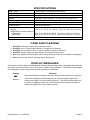
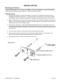
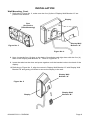
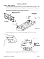
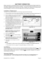
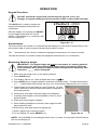
ProDoc Series
DHRWM
Digital Height Rod
(Wall Mounted Digital Height Rod)
Owner’s Manual
0044-M372-O1 Rev A
05/08
CARDINAL SCALE MFG. CO.
PO Box 151 y Webb City, MO 64870
Ph: 417-673-4631 y Fax: 417-673-5001
www.detectoscale.com
Technical
Support: Ph: 866-254-8261 y [email protected]
0044-M372-O1
y DHRWM
Page 1
0044-M372-O1 y DHRWM
Page 2
INTRODUCTION
Thank you for purchasing our Detecto ProDoc Series DHRWM Wall Mounted Digital Height Rod.
Your digital height rod has been designed for simple and straightforward use and to assure
accuracy and dependability for years to come.
Please read this manual thoroughly before attempting to use your scale and keep it handy for
future reference. It contains important instructions for installation and proper operation of your
scale.
FCC Compliance Statement
WARNING! This equipment generates uses and can radiate radio frequency and if not installed
and used in accordance with the instruction manual, may cause interference to radio
communications. It has been tested and found to comply with the limits for a Class A computing
device pursuant to Subpart J of Part 15 of FCC rules, which are designed to provide reasonable
protection against such interference when operated in a commercial environment. Operation of
this equipment in a residential area may cause interference in which case the user will be
responsible to take whatever measures necessary to correct the interference.
You may find the booklet "How to Identify and Resolve Radio TV Interference Problems"
prepared by the Federal Communications Commission helpful. It is available from the U.S.
Government Printing Office, Washington, D.C. 20402. Request stock No. 001-000-00315-4.
All rights reserved. Reproduction or use, without expressed written permission, of editorial or
pictorial content, in any manner, is prohibited. No patent liability is assumed with respect to the
use of the information contained herein. While every precaution has been taken in the
preparation of this manual, the Seller assumes no responsibility for errors or omissions. Neither
is any liability assumed for damages resulting from use of the information contained herein. All
instructions and diagrams have been checked for accuracy and ease of application; however,
success and safety in working with tools depend to a great extent upon the individual’s accuracy,
skill and caution. For this reason the Seller is not able to guarantee the result of any procedure
contained herein. Nor can they assume responsibility for any damage to property or injury to
persons occasioned from the procedures. Persons engaging the procedures do so entirely at
their own risk.
Serial Number_______________________
PRECAUTIONS
Date of Purchase ____________________
Before using this scale, read this manual
and pay special attention to all "WARNING"
symbols:
Purchased From_____________________
___________________________________
___________________________________
___________________________________
RETAIN THIS INFORMATION FOR FUTURE USE
0044-M372-O1 y DHRWM
IMPORTANT
ELECTRICAL
WARNING
Page 1
SPECIFICATIONS
Height Units ......………………… Feet/Inches or Centimeters (selectable)
Height Range…………………….. 3’ 7” to 6’ 7” (110 to 200 cm)
Power Requirements …………… Four (4) “AA” size Alkaline batteries (not included)
Display …………………………… Five digit, seven segment, 1.0 inch (25 mm) high LCD
Cable Length ……………………. 69” (175 cm)
Operation Temperature ………… 50 to 104 ºF (+10 to +40 ºC)
Function Keys …………………… UNITS and ON/OFF
Dimensions
Display ..…………..…............. 5.25” H x 7.75” W x 2.125” D (13.4 cm x 19.7 cm x 5.4 cm)
Height Rod (includes bracket)
(collapsed) ….……………… 43.3” H x 3.35” W x 2.56” D (111.0 cm x 8.5 cm x 6.5 cm)
(extended) ………………….. 98.8” H x 3.35” W x 2.56” D (251.0 cm x 8.5 cm x 6.5 cm)
Shipping Weight …..……………. 8.20 lb (3.70 kg)
CARE AND CLEANING
1.
2.
3.
4.
5.
6.
DO NOT submerge height rod or display in water.
DO NOT pour or spray water directly on height rod or display.
DO NOT use acetone, thinner or other volatile solvents for cleaning.
DO NOT expose height rod and display to temperature extremes.
DO clean height rod and display with a damp soft cloth and mild non-abrasive detergent.
DO remove power before cleaning with a damp cloth.
DISPLAY MESSAGES
The Detecto ProDoc Series DHRWM Wall Mounted Digital Height Rod is equipped with software
that tests various portions of its circuitry and verifies proper operation. The following messages
are displayed to alert the operator should a problem be detected.
Display
Meaning
BAt
Displayed when the batteries are near the point they need to be replaced.
-----
This will be displayed when attempting to use the Digital Height Rod
without the height rod in the starting position. The inner sliding tube must
be down completely inside the outer stationary tube and the headpiece
folded flat against the outer stationary tube.
0044-M372-O1 y DHRWM
Page 2
UNPACKING
Remove the height rod, display, hardware pack and other components from the shipping carton.
After removing from the carton, check for any damage that may have taken place during
shipment. Keep and use the original carton and packing material for return shipment if it should
become necessary. The purchaser is responsible for filing all claims for any damages or loss
incurred during transit. Remove all plastic wrapping, foam fillers and cardboard material from
the height rod, display and other components. You should have the following components:
(1) Detecto Wall Mounted Digital Height Rod (DHRWM)
(1) Remote Display
(1) Display Wall Bracket “A”
(Includes four (4) feet for desk or table mounting)
(1) Display Wall Bracket “B”
(1) Hardware Pack, containing:
(4) M3.0x25 Screws
(4) Plastic Wall Anchors
M3.0x25 Screw
Plastic Wall Anchor
ASSEMBLY
The DHRWM does not require any assembly. After installing batteries, the DHRWM is ready for
wall mounting and operation.
BATTERY INSTALLATION
1. Turn the display over so that the keypad is facing down and locate the rectangular battery
cover on the back of the display.
2. Remove the cover, install four (4) “AA” size batteries1 and then replace the cover.
3. Turn the display over to the normal operating position.
4. Make sure the height rod is in the starting position.
5. Press the ON/OFF key to turn the display on.
6. The display will turn on, show all digits then show 11)0 cm.
7. If the display did not turn on, remove the battery cover and check for one or more improperly
positioned batteries.
8. The digital height rod and display are now ready to be installed.
1
See page 7 for detailed instructions on installing the batteries.
0044-M372-O1 y DHRWM
Page 3
INSTALLATION
Mounting the Height Rod
1. Choose the location to mount the height
rod on the wall. The location should be
free of temperature extremes and water. It
should be where it is within easy reach of
the operator.
2. Make certain the structure and mounting
hardware are of sufficient strength to
support the height rod. The mounting
bracket should be securely fastened to the
wall so that it cannot break loose from the
mounting surface.
3. Referring to Figure No. 1 and using the
height rod as a template, place the height
rod against the wall and mark the holes to
use to mount it. The lower mounting hole
should be 6 13/32 inches (162.5 mm) from
the floor and the upper mounting hole
should be 30 25/32 inches (782.0 mm)
from the lower hole.
4. Remove the height rod and drill two (2)
13/64” (5 mm) holes in the wall for the
mounting wall anchors.
30 25/32”
(782 mm)
5. Insert the wall anchors in the wall until they
are flush with the wall.
6. Place the height rod against the wall and
insert the two (2) M3.0x25 screws through
the bracket and into the wall anchors.
7. Partially tighten the screws to hold the
height rod in place.
8. Make sure the bottom of the height rod is
25/64 inch (10 mm) from the floor and then
tighten the screws to secure the height rod
to the wall.
6 13/32”
(162.5 mm)
25/64”
(10 mm)
Floor
Figure No. 1
0044-M372-O1 y DHRWM
Page 4
INSTALLATION
Mounting the Display
The DHRWM display has a 69” (175 cm) cable to allow it to be placed at a convenient position
away from the height rod. A bracket is included to mount the display on a wall or the bracket
(and included feet) can used to place it on a desk for easy viewing.
Wall Mounting
1. Choose the location to mount the display on the wall. The location should be free of
temperature extremes and water. It should be where the display can be easily viewed,
not subject to direct sunlight and where the keypad is within easy reach of the operator.
2. Make certain the structure and mounting hardware are of sufficient strength to support the
display. The mounting bracket should be securely fastened to the wall so that it cannot
break loose from the mounting surface.
3. Referring to Figure No. 2 and using Display Wall Bracket “B” for a template, place the
bracket against the wall (notch and arrow pointing up) and mark the holes to use to mount
it. Remove the bracket and drill two (2) 13/64” (5 mm) holes in the wall for the mounting
wall anchors.
4. Insert the wall anchors in the wall until they are flush with the wall.
5. With the notch and arrow pointing up on Display Wall Bracket “B”, insert the two (2)
M3.0x25 screws through the bracket and into the wall anchors.
6. Tighten the screws to secure the bracket to the wall.
Figure No. 2
13/64” (5 mm)
Hole in Wall
Plastic Wall Anchor
Display Wall Bracket “B”
M3.0x25 Screw
0044-M372-O1 y DHRWM
Page 5
INSTALLATION
Wall Mounting, Cont.
7. Referring to Figure No. 3, make sure the four (4) feet of Display Wall Bracket “A” are
placed in the bracket.
Display
Feet
(for Desk or
Table Mounting)
Display Wall
Bracket “A”
Figure No. 3
Figure No. 4
8. Next, locate the four (4) slots on the back of the display and align them with the four (4)
tabs on the Display Wall Bracket “A”. Refer to Figure No. 4.
9. Insert the tabs into the slots and press together until the bracket locks to the back of the
display.
10. Referring to Figure No. 5, align the cutout in Display Wall Bracket “A” with Display Wall
Bracket “B” and gently pull down to secure the display to the wall.
Display Wall
Bracket “A”
Figure No. 5
Display
0044-M372-O1 y DHRWM
Display Wall
Bracket “B”
Page 6
INSTALLATION
Desk or Table Mounting
1. The location chosen should be a stable, level surface (either a desk or solid table), free of
temperature extremes and water. The display should be where it can be easily viewed,
not subject to direct sunlight and where the keypad is within easy reach of the operator.
2. Referring to Figure No. 6, remove the four (4) feet from inside Wall Bracket “A” and install
them in each corner of the bracket as shown in Figure No. 7.
Remove Feet from
Display Wall Bracket “A”
Install Feet in
Display Wall
Bracket “A”
Figure No. 6
Figure No. 7
3. Next, locate the four (4) slots in the back of the display. Refer to Figure No. 8.
Figure No. 8
Display
Figure No. 9
Display Wall
Bracket “A”
with
Feet Installed
Slot
Tab
4. Referring to Figure No. 9, align and insert the tabs on the bracket with the slots in the
display back and press together until the bracket locks to the back of the display.
0044-M372-O1 y DHRWM
Page 7
BATTERY OPERATION
Battery operation is a standard feature of the ProDoc Series Wall Mounted Digital Height Rod,
although the batteries are optional (not included). You must first obtain and install four (4) "AA"
size alkaline batteries before operations can begin. Batteries are contained in a battery holder
inside the display. Access is via a removable cover on the back of the display.
Installation / Replacement
To install or remove the batteries, the following steps should be followed:
1. If wall mounted, remove the display by sliding it up and away from Display Wall Bracket “B”.
2. Turn the display over so that the keypad is facing down on the desk or table.
3. Remove Display Wall Bracket “A” and
locate the rectangular battery cover on the
back of the display.
4. To install or replace the batteries, first
remove the battery cover by pushing in on
the tab and lifting it up. See Figure No. 10.
Push in
and lift
here.
Battery
Cover
5. If installing new batteries, proceed to step
6. If replacing the batteries, remove all
four (4) batteries from the battery holder,
then proceed to step 6.
6. Install the four (4) new “AA” size batteries
in the battery holder, noting the polarity
markings located in the battery holder.
See Figure No. 11.
Figure No. 10
7. Replace the battery cover (it will click
when locked in place) and return the
display to the upright position.
8. Press the ON/OFF key.
9. The display will turn on, show all digits
then show 11)0 cm.
10. If the display did not turn on, remove the
battery cover and check for one or more
improperly positioned batteries.
11. The display is now ready for normal
operation.
Figure No. 11
NOTE!
y If the display is wall mounted, follow steps 8 to 10 on page 5 to re-install on the wall.
y
Follow steps 3 and 4 on page 6 if using the display on a desk or table.
Low Battery
When the batteries are near the point they need to be replaced, the display will show BAt. If the
battery voltage drops too low for accurate measurements, the display will automatically shut off
and you will be unable to turn it back on. When the BAt message is displayed, the operator
should replace the batteries.
Automatic Shutoff
The Automatic Shutoff feature will turn the display off after one (1) minute of inactivity to
prolong battery life. To turn the display back on, you simply press the ON/OFF key.
0044-M372-O1 y DHRWM
Page 8
OPERATION
Keypad Functions
DO NOT operate the keypad with pointed objects (pencils, pens, etc).
Damage to keypad resulting from this practice is NOT covered under warranty.
The UNITS key is used to change the
height units between feet/inches and
centimeters.
With the display off, pressing the ON/OFF
key will apply power and turn on the
display. If the display is on, pressing it will
turn the display off.
Annunciators
Figure No. 12
The annunciators are turned on to indicate that the display is in the mode corresponding to the
annunciator label or that the status indicated by the label is active.
The ' " annunciators are turned on when the displayed measurement is in feet and inches.
The cm annunciator is turned on when the displayed measurement is in centimeters.
Measuring Patient’s Height
IMPORTANT! The digital height rod must be returned to its “starting position”
before every use (the inner sliding tube must be down completely inside the
outer stationary tube) and the headpiece folded flat against the stationary tube.
Otherwise, ----- will be displayed.
1. Make sure the height rod is in the starting position.
2. Press ON/OFF key.
3. The display will turn on, show all digits then show 110.0cm.
4. Press UNITS key to toggle between centimeters and feet/inches. The cm (centimeters)
or ( ' " ) (feet/inches) annunciator will turn on to show which measurement unit is active.
5. Grasp height rod at the hinge pin (see Figure No. 13) and
raise it well above patient’s head and then lift headpiece to
horizontal position.
6. Patient may now step under the height rod headpiece.
7. Carefully lower height rod until headpiece rests on top of
patient’s head.
8. Read and record height of patient.
9. While holding headpiece horizontal, raise height rod well
above patient’s head.
10. Patient may now step away from height rod.
11. Return height rod to starting position.
12. To turn display off, press ON/OFF key.
Figure No.13
NOTE! If the DHRWM is not used again within one (1) minute, the Automatic Shutoff feature
will turn the display off.
0044-M372-O1 y DHRWM
Page 9
0044-M372-O1 y DHRWM
Page 10