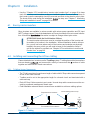
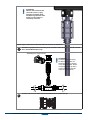
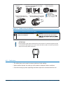
1
Enecsys Enables
OPTIMAL
SOLAR
SOLUTIONS
intelligent reliable power
Enecsys AC Module Instruction Guide
www.enecsys.com | [email protected]
Document number: IOG1120412
PRELIMINARY version (1.0)
December 4, 2012
Contents
Chapter 1 Important Safety Instructions
1.1.Audience .......................................................................................................................................................................................................
1.2.Products covered by these instructions ...............................................................................................................................................
1.3.Conventions used in this manual...........................................................................................................................................................
1.4.Safety ............................................................................................................................................................................................................
Chapter 2 Installation Recommendations
2.1.Site requirements for Enecsys micro inverters and monitoring system ......................................................................................
2.2. Install the Enecsys Gateway ...................................................................................................................................................................
2.3. Plan the cabling layout ............................................................................................................................................................................
2.4. Lay out AC cabling; test, then connect to Point of Common Connection..................................................................................
2.5. Connect the AC Cabling to the AC Module .......................................................................................................................................
2.6. Confirm communications between micro inverters and Gateway...............................................................................................
2.7. Set up the new installation on the Monitoring website...................................................................................................................
2.8. Finalize installation and user details; launch the installation ........................................................................................................
Chapter 3 Installing the Gateway
3.1.Mounting the gateway ............................................................................................................................................................................
3.2. Connecting the gateway........................................................................................................................................................................
3.2.1. Connecting the Gateway to an Ethernet router...............................................................................................................
Chapter 4 Using the Enecsys Gateway
4.1.Enecsys Gateway Setup ..........................................................................................................................................................................
4.2. Gateway Operation and Installer Functions .....................................................................................................................................
4.3. Navigating views using touch controls...............................................................................................................................................
4.3.1. Gateway energy graph view................................................................................................................................................
4.3.2. Gateway installer settings view ........................................................................................................................................
Chapter 5 Using Enecsys Repeaters
5.1.Failure to establish reliable communications....................................................................................................................................
5.2. Using Repeaters ......................................................................................................................................................................................
5.3. Installing one or more single repeaters ..............................................................................................................................................
5.4. Mounting the single repeater ..............................................................................................................................................................
5.4.1. Connecting the single repeater..........................................................................................................................................
Chapter 6 Installation
6.1.Enecsys micro inverters ..........................................................................................................................................................................
6.2. Installing and connecting the AC bus cabling.................................................................................................................................
6.2.1. T-Cabling System Components .........................................................................................................................................
6.3. Connections .............................................................................................................................................................................................
6.3.1. T-cabling AC connection .....................................................................................................................................................
6.3.2. Cable Joiner ............................................................................................................................................................................
6.4. Micr o inverter technical details ..........................................................................................................................................................
Chapter 7 Monitoring Setup and Installation Launch
7.1.Installer login for Enecsys Monitoring System ..................................................................................................................................
7.2. Adding a new installation......................................................................................................................................................................
2
Installation
and Operation Guide Enecsys LLC • 275 Redwood Shores Drive • Redwood Shores, CA 94065 • www.enecsys.com
4
4
4
5
5
7
7
7
7
7
8
8
8
8
9
10
10
11
12
12
14
15
16
16
20
20
20
21
22
22
24
24
24
24
26
26
28
29
30
30
30
Step 1: Input the installation owner’s details..............................................................................................................................
Setup 2: Enter installation site details. ..........................................................................................................................................
Step 3: Input the system information. ...........................................................................................................................................
Step 4: Add gateway serial number(s). ........................................................................................................................................
Step 5: Begin layout by adding a section.....................................................................................................................................
Section Details ...................................................................................................................................................................................
Step 6: Enter section details. ..........................................................................................................................................................
Step 7: Adjust section layout. .........................................................................................................................................................
Optional: Manual Adjustments and Serial Numbers ...............................................................................................................
Optional: Saving a pending installation.......................................................................................................................................
7.3. Installation finalization and launch.....................................................................................................................................................
Step 1: Find the pending installation.............................................................................................................................................
Step 2: Drag-and-drop inverter serial numbers. ........................................................................................................................
Step 3: Check work and launch installation ................................................................................................................................
Step 4: Inform the customer. ..........................................................................................................................................................
Chapter 8 Troubleshooting
38
8.1.Inverter LED Functions ...........................................................................................................................................................................
8.2. Communication.......................................................................................................................................................................................
8.3. Monitoring ................................................................................................................................................................................................
Chapter 9 PV module/ micro inverter serial number form
NNN-NNN r001
30
31
31
31
32
32
32
33
34
35
35
35
35
36
37
Enecsys
38
38
39
40
Installation and Operation Guide
3
Chapter 1
Important Safety Instructions
SAVE THESE INSTRUCTIONS – These instructions pertaining to Enecsys micro inverters
must be followed during installation and maintenance of equipment with which they are integrated.
1.1. Audience
These instructions are intended for installers and electricians involved in the installation and
set up of PV systems using Enecsys micro inverters. It is expected that installers will have
knowledge of the necessary steps needed for safe and successful installation of all portions of
the PV Installation. Electricians must have knowledge of the electrical codes and regulations
of their
country as well as safe methods of practice.
Installers can view the Enecsys installation video on the website:
http://enecsys.com/resources/videos.php
1.2. Products covered by these instructions
This manual covers the following products:
• Micro inverter 220-60-MM
• Micro inverter 240-60-MM
• Micro inverter 260-60-MM
• Micro inverter 280-60-MM
• Micro inverter 300-60-MM
• Gateway
• Repeater
• Monitoring software
4
Installation
and Operation Guide Enecsys LLC • 275 Redwood Shores Drive • Redwood Shores, CA 94065 • www.enecsys.com
1.3. Conventions used in this manual
The following conventions are used throughout this manual. These conventions should be
noted and followed at all times.
WARNING
Warning statements must be heeded at all times. A warning symbol indicates that a process or instrument has the potential to harm or cause
lethal injury if the correct method of handling is not employed.
!
!
CAUTION
Caution Statements are used to indicate where a part of a process may
have the potential to damage equipment. Caution statements should be followed at all times.
ATTENTION:
Attention statements are used to indicate where a part of the process has a
special requirement. Attention statements should be followed at all times.
1.4. Safety
Original equipment manufacturers must provide adequate safety warnings relevant to their
product.
Before installing and using equipment with integrated Enecsys micro inverters, please ensure
that you have fully read and understand all of the installation instructions and heed all warnings and cautions given.
The following warnings apply
to Enecsys components:
WARNING
AC Cable harness must be connected to the mains utility grid by a
electrician.
!
CAUTION
Enecsys micro inverters, gateways and repeaters contain no user-serviceable parts. Do not attempt to open or repair. Opening or tampering with the
Enecsys micro inverter, gateway or repeater will void the warranty.
• a component
If
fails, contact the supplier.
•
NNN-NNN r001
modules
New
that have micro inverters that appear to be damaged should
not be installed: contact the supplier.
Enecsys
Installation and Operation Guide
5
!
ATTENTION
The gateway and repeater are intended for stationary indoor use only.
•
not
Domount in a location where they will be exposed to direct/excessive
solar and/or heat radiation.
•
•
•
•
6
notDo
expose to heat-trap conditions or to water condensation.
notDo
use liquid or aerosol cleaners when cleaning: clean only with a damp
cloth.
notDo
use near water.
Transition
of these items between temperature extremes may cause condensation on some of the internal parts. If you notice condensation on or
behind the product’s display window, allow it to dry naturally before re-connecting to the main electrical supply.
Installation
and Operation Guide Enecsys LLC • 275 Redwood Shores Drive • Redwood Shores, CA 94065 • www.enecsys.com
Chapter 2
Installation Recommendations
2.1. Site requirements for Enecsys micro inverters and monitoring system
The following things are required if the Enecsys Monitoring system is used:
• The customer must have a broadband Internet connection.
• There must be an unused Ethernet port on the customer’s router to connect to the Enecsys Gateway so the Gateway can communicate with the online monitoring system. The
information provided by the Enecsys Gateway is used to troubleshoot the installation as it
progresses. See “Chapter 4 Using the Enecsys Gateway” on page 12.
• If the roof is made of metal or lined with metal foil, it may be necessary to install one or
more repeaters right below it, in a loft or attic, for example. See “Chapter 5 Using Enecsys
Repeaters” on page 21.
• If a repeater or repeaters are necessary, there must be power outlets in the required locations. See “5.2. Using Repeaters” on page 21.
2.2. Install the Enecsys Gateway
At the earliest possible stage during the onsite installation, the installer should connect the
Enecsys Gateway to the customer’s router using the Ethernet cable provided. When the Gateway is powered up, it will be ready to start monitoring the micro inverters as soon as they are
connected to the PV panels on an individual basis. (See “3 Installing the Gateway”.)
Q: Why is it recommended to set up the Gateway as early as possible during the installation?
A: Once the Gateway is functioning it will show which individual inverters have DC
connections, even without AC power to the inverters. Solving connection issues before
.
2.3. Plan the cabling layout
The installer must follow the installation design for module layout. Trunk cabling comes in
portrait and landscape spacing
and the system includes a variety of
to
needs.
accommodate
2.4. Lay out AC cabling; test, then connect to Point of Common Connection
All connections and terminations must be completed per the install la ti on design. See “6.2.
Installing and connecting the AC bus cabling” on page 28.
When all of the AC cabling is in place, but before it is connected to the point of common connection (POCC), it must be inspected and tested to verify proper connection and compliance
with the relevant electrical installation standards.
!
NNN-NNN r001
WARNING
Connection of the AC cable to the mains utility grid must only be done by
personnel.
Enecsys
Installation and Operation Guide
7
2.5. Connect the AC Cabling to the AC Module
See “6.2. Installing and connecting the AC bus cabling” on page 24.
2.6. Confirm communications between micro inverters and Gateway
By looking at the screen on the Gateway unit, the installer can see if the Gateway is receiving a good signal from all of the micro inverters. See “4.1. Enecsys Gateway Setup” on page
12.
If communications have not been established, it may be necessary to install one or more repeaters. See ”Chapter 5 Using Enecsys Repeaters” on page 21.
2.7. Set up the new installation on the Monitoring website
• If the installer has not worked with Enecsys micro inverters before, it’s time to set up an
Installer Account. For setup details, see section “7.1. Installer login for Enecsys Monitoring
System” on page 30.
• Before installing the gateway, the installer should log onto the Monitoring website with the
installer account and set up the individual installation. The installer will need details such as
the homeowner’s name and email address, street address of site, estimated yearly energy
production, and average cost of electricity per kilowatt-hour.
2.8. Finalize installation and user details; launch the installation
•
8
See “7.3. Installation
and launch” on page 35.
Installation
and Operation Guide Enecsys LLC • 275 Redwood Shores Drive • Redwood Shores, CA 94065 • www.enecsys.com
Chapter 3
Installing the Gateway
GATEWAY
ETHERNET CABLE
ROUTER
5V DC
5V DC
Figure 1. Enecsys Gateway Setup
Gateway scope of delivery
• 1 Enecsys Gateway
• 1 Plug-top power adapter - 5V DC 1A
• 1 Ethernet cable: length 2m
• Assorted attachment hardware
Figure 2. Enecsys Gateway scope of delivery
NNN-NNN r001
Enecsys
Installation and Operation Guide
9
3.1. Mounting the gateway
!
ATTENTION
The gateway should be installed in the upright position, either by permanent
attachment or standing upright. This is for optimum antenna performance.
• The gateway must be installed indoors near a mains power socket.
• It can be freestanding: rotate out the plastic feet for stability.
• It can be wall mounted using two screws in the position shown in the diagram.
• It can be mounted using adhesive pads in the position shown in the following diagram.
Screw fixing points
9 cm (3.5 inches)
Adhesive pad fixing
points (approximate)
Figure 3. Gateway mounting points
3.2. Connecting the gateway
• The Enecsys gateway requires the following connections:
5V DC power input from the plug-top power supply.
Ethernet connection to the customer’s router.
• When the Enecsys gateway powers up, its screen will display the gateway initial setup
screen (see “Gateway initial display screen” on page 11). Language, installation location,
and date/time are selected: then basic information will display immediately.
10
Installation
and Operation Guide Enecsys LLC • 275 Redwood Shores Drive • Redwood Shores, CA 94065 • www.enecsys.com
3.2.1. Connecting the Gateway to an Ethernet router
Connect one end of the supplied Ethernet cable to
a spare Ethernet port on the rear of the customer’s
router.
ROUTER
ETHERNET CABLE
Connect the other end of the supplied Ethernet cable
to the Ethernet port on the left hand side of the Enecsys gateway.
Connect the supplied 5V DC plug-top power adapter
jack to the 5V DC-in power socket on the left hand
side of the Enecsys gateway.
Connect the 5V DC plug-top power adapter to a
mains power source. The gateway will power up immediately.
ETHERNET
CABLE
5V DC
Once installed and when all the system components
are showing correctly, do not disconnect or move a
gateway. This may interfere with the transmission of
data resulting in incorrect values being displayed.
Figure 4. Gateway initial display screen
NNN-NNN r001
Enecsys
Installation and Operation Guide
11
Chapter 4
Using the Enecsys Gateway
The gateway should already be installed: see “Connecting the gateway” on page 10.
4.1. Enecsys Gateway Setup
For a new gateway that has not been
the initial display screen is the Installation
Wizard. There are six steps to complete the setup.
Select language
and click “NEXT”
arrow
Step 1. Choose language
Select connection
type and click “NEXT”
arrow
Step 2. Choose connection type
12
Gateway
Guide Enecsys LLC • 275 Redwood Shores Drive • Redwood Shores, CA 94065 • www.enecsys.com
Select installation
country and click
“NEXT” arrow
Step 3. Select country of installation
Use “+” and “-” to
change settings, then
click “NEXT” arrow
Step 4. Set date and time
Verify that all the inverter serial numbers
appear, then click
“NEXT” arrow
NNN-NNN r001
Enecsys
Gateway Guide
13
Step 5. Check that inverters are reporting
Step 6. Acknowledge installation completion
4.2. Gateway Operation and Installer Functions
• When the installation is complete, the view changes to the gateway default.
• The default view is what the installation owner sees. The installation owner can also switch
to a view that shows daily energy generation over a period of thirty days.
• Installer functions are inverter setup and system diagnostics. That portion is password protected.
1
2
a
4
3 d
c
b
5
Figure 5. Gateway default view: functional areas
During routine operation, this screen shows enough information for the user to see that the
inverters are operating and reporting to the monitoring system.
14
Gateway
Guide Enecsys LLC • 275 Redwood Shores Drive • Redwood Shores, CA 94065 • www.enecsys.com
Table 1.
Gateway default view functional areas
Area
Description
1
Status Bar: General information
Display of system time and date
2
Status Bar: Component communication
status
a. Number of inverters communicating
b. Number of repeaters communicating
3
Status Bar: Communication link
c. Communication connection: Ethernet or stand-alone
d. Communication linked to internet
4
5
Daily Energy at-a-glance
Compares the day’s energy production to lifetime data
Active areas
Navigate from default view to power generation comparison
graphs and installer functions
Table 2.
Status bar troubleshooting
Status bar display
Description
State
Number of online inverters
“0” (zero) is the number displayed.
There is no communication between the
gateway and inverters. It may be necessary to install one or more repeaters.
Number of online inverters
Number displayed equals the
number of inverters.
Communication is good and connections
are properly made.
Number of online inverters
Number displayed does not equal
the number of inverters.
Possible malfunction, pinched inverter cabling, or connection problem. User should
contact the installer.
Installer may need to test connection. It
may be necessary to move the Gateway
and or repeater(s). If possible, troubleshoot via the Monitoring Site.
4.3. Navigating views using touch controls
Figure 6. Gateway navigation touch controls
Navigate to:
energy graph
Navigate to:
installer settings
• Once the gateway has been installed, the default view will display.
NNN-NNN r001
Enecsys
Gateway Guide
15
• To access alternate views, use the touch controls on the right side of the screen.
• The top “Energy Production” symbol goes to the default view when selected.
• The middle “Energy Graph” symbol goes to a graph that represents energy generation over
the past 30 days.
• The bottom “Installer Settings” symbol allows users view inverter, gateway, repeater, and
server
ration settings. Installers can use a password to access specialized functions.
4.3.1. Gateway energy graph view
Figure 7. Energy generation graphs
4.3.2. Gateway installer settings view
The Settings screen is viewable by all users, but Server Settings, Maintenance Mode, and
the Installation Wizard can only be accessed by users with an Installer password. The ability
to change inverter, gateway, repeater, and server settings; to access Maintenance Mode, and
to
e the installation should be restricted to users who are trained in these functions
by Enecsys.
Figure 8. Gateway Installer Settings
16
Gateway
Guide Enecsys LLC • 275 Redwood Shores Drive • Redwood Shores, CA 94065 • www.enecsys.com
Figure 9. Inverter Settings
This screen is
read-only
Figure 10. Gateway Settings
This screen is
read-only
Figure 11. Repeater Settings
This screen is
read-only
NNN-NNN r001
Enecsys
Gateway Guide
17
Figure 12. Server Settings
This screen is
read-only
Figure 13. Maintenance Mode Settings
This screen is
password
protected
!
ATTENTION
Attempting to rerun the installation for an already installed system requires a password.
This is to prevent inadvertent change of settings, data loss, and disruption of the correct
operation of the system.
Figure 14. Installation Wizard Dialog
18
Gateway
Guide Enecsys LLC • 275 Redwood Shores Drive • Redwood Shores, CA 94065 • www.enecsys.com
!
NNN-NNN r001
ATTENTION
After the installation is complete, the gateway should be returned to the default
view and left that way during customary operation.
Enecsys
Gateway Guide
19
Chapter 5
Using Enecsys Repeaters
The Enecsys gateway receives signals from the micro inverters on the roof and broadcasts
the data over the Internet to the Enecsys Monitoring server. If the gateway cannot receive
strong enough signals from micro inverters, a repeater installed nearer the PV modules on the
roof will receive the signals, boost them, and then relay them to the gateway.
In some cases it may be necessary to install more than one single repeater to boost signals
two or more times before they reach the gateway.
5.1. Failure to establish reliable communications
• If the Enecsys gateway displays the check symbol “ ” on the Default View screen, communications link between the gateway and the inverters is established and is reliable. See
“Figure 20. Enecsys Gateway Default View” on page 23.
• If the gateway does not display the green check symbol, the communications link may not
be strong enough to be reliable. It may be necessary to install one or more single repeaters.
See “5.3. Installing one or more single repeaters” on page 21.
5.2. Using Repeaters
• If the “X” symbol is displayed on the gateway Installer Mode communication status, one
or more Enecsys single repeaters can be used. Start with one and observe for the “X” to
change to a “ ”.
• If the “?” symbol is displayed, signal quality is poor. Distance between the inverters and
gateway may be the problem: installing a second single repeater may help.
The diagram shows a building with two single repeaters between the PV modules on the roof
and the Enecsys gateway on the ground
Figure 15. Repeaters, Gateway, and Router
20
Installation
and Operation Guide Enecsys LLC • 275 Redwood Shores Drive • Redwood Shores, CA 94065 • www.enecsys.com
5.3. Installing one or more single repeaters
GATEWAY
5V DC
5V DC
Figure 16. Enecsys Repeater
• Install the single repeater in the roof space, directly below the micro inverters. See “Figure
15. Repeaters, Gateway, and Router” on page 20.
• It must be installed near an outlet/mains power socket for the plug-top power adapter.
• If the installation requires a second single repeater, this should be located on one of the
intermediate
between the repeater in the roof space and the Enecsys gateway on the
as shown in the diagram in section “5.2. Using Repeaters” on page 20.
ground
Figure 17. Repeater scope of delivery
• 1 Single repeater unit.
• 1 Plug-top power adapter -- 5V DC 1A
• Assorted attachment hardware
NNN-NNN r001
Enecsys
Installation and Operation Guide
21
5.4. Mounting the single repeater
• The single repeater must be installed indoors near an outlet/mains power socket.
• It can be freestanding, either upright as shown in the illustration, or laid
• It can be wall mounted using two screws in the position shown in the diagram.
• It can be mounted using sticky pads in the position shown in the diagram.
SCREW FIXING POINTS
50 mm
CABLE TIE
FIXING POINT
ADHESIVE FIXING POINTS
Figure 18.
5.4.1. Connecting the single repeater
Figure 19. 5V power input to repeater
The single repeater requires 5V DC power input from the plug-top power supply.
• Pass the DC power cable through the slot in the lower side of the case as shown in “Figure
19. 5V power input to repeater”.
• When the DC power adapter receives power from the outlet/mains, the single repeater will
start working immediately.
• Go through the initial steps of the Gateway Installation Wizard: see “4.1. Enecsys Gateway
Setup” on page 12.
• Observe the communication connection quality on the Enecsys gateway default view screen.
It should now display:
A The correct number of inverters.
B The repeater.
22
Installation
and Operation Guide Enecsys LLC • 275 Redwood Shores Drive • Redwood Shores, CA 94065 • www.enecsys.com
C The communication check
symbol.
A
B
C
Figure 20. Enecsys Gateway Default View
If the correct number of inverters and repeater are not showing, consult the troubleshooting
section of the Gateway Installation “Table 2. Status bar troubleshooting” on page 15.
• Plug the power adapter into the outlet/mains. When the DC power adapter receives power
from the outlet/mains, the single repeater should start working immediately.
!
NNN-NNN r001
ATTENTION
After the installation is complete, the gateway should be returned to the default
view and left that way during customary operation.
Enecsys
Installation and Operation Guide
23
Chapter 6
Installation
• Use the ““Chapter 9 PV module/micro inverter serial number form” on page 40 to keep
track of the inverter serial numbers as they are installed in place. The removable stickers on
the inverter (near the nameplate) should be removed and stuck to the sheet to refer to later.
tion step: see ”Chapter 7 Monitoring
The sheet will be used during the installation
Setup and Installation Launch” on page 30 for details.
6.1. Enecsys micro inverters
Micro inverters are available in various models with various power capacities and DC input
MPPT voltage ranges. Consult the datasheets on Enecsys’s website for most current information. All technical
information is subject to change without prior notice.
!
ATTENTION: Retain the Serial Number Stickers
The serial number stickers are used to correlate the position of the inverter and
its module to its location in the installation. Without installation location information, you will not know where each of the inverters and modules are physically
located in the array, which you will need to know for the installation setup. A
grid for the stickers is provided: see “Chapter 9 PV module/micro inverter serial
number form” on page 40.
6.2. Installing and connecting the AC bus cabling
Frame-attached micro inverters use the T-cabling system. T-cabling has molded connections
and comes with a variety of connectors that sections of cable
that are already
together and terminate AC branch connections.
6.2.1. T-Cabling System Components
• The T-Cable consists of a continuous length of cable with AC Drop cable connectors spaced
at one or two meter intervals.
• T-cables must be cut to the appropriate length for a branch circuit and terminated with a
cable end cap.
• Each AC Drop Cable connects to an inverter. Unused drop cable connectors must be covered by permanent weatherproof female caps.
• Field-installable male and female connectors are available to add more cabling options.
Drop sections to inverters
Female Weatherproof End Cap
AC
POCC
Cable End Cap
Trunk section forms a branch
Cable Joiner
Figure 21. T-Cabling
24
Installation
and Operation Guide Enecsys LLC • 275 Redwood Shores Drive • Redwood Shores, CA 94065 • www.enecsys.com
Weatherproof Cap Female
Optional
Optional
Field Installable
Field Installable
Connector Male Connector Female
Cable Joiner
TCable End Cap
Figure 22. Connectors and Caps
WARNING
There must not be any exposed AC connection points. These AC points will be live
when the system is connected to the utility grid. Always use the end caps provided
to seal the open connection points on the AC drop cables.
WARNING:
Depending on the model used, the maximum number of micro inverters in any AC
branch must not exceed the maximum number allowed.
!
!
!
ATTENTION
A “protective cap” is not a permanent end cap: It is purely for protecting the inverter
connectors during shipping. It should stay on the inverter connector to keep it dry
during the installation process. Discard the protective caps only while making the
inverter connections. Do not attempt to re-use protective caps.
ATTENTION
Do not allow the cable to lie in contact with the roof surface. If necessary, route the
cable neatly along the racking using cable clips.
ATTENTION
To avoid damaging the inverter or cables, do not force together the AC Drop Cable
and inverter AC connectors. The connectors are keyed to prevent misalignment.
• Observe the direction of the drop cable connector: it should have a light-colored
triangle-shaped orientation mark. The inverter AC Out connector has the same
mark for orientation purposes. See “Figure 27. T-Cable to Inverter AC Connector”
on page 33 for details.
• Do not twist the cabling in the process of connection-- tension can damage the
cable and connectors over time.
NNN-NNN r001
Enecsys
Installation and Operation Guide
25
6.3. Connections
WARNING:
All electrical connectors must be dry before making any connections and must
be kept dry during the installation process. Inverter AC cables are supplied with
protective end caps that should only be removed immediately before making
the connections.
T-Cabling System
1 AC connection Roof
per Surface
inverter to the T-cabling system to
create a branch circuit. Inverter logo side facing roof surface
Table 3.
Micro inverter AC connector pin out
T Drop Cable Connector
receptacles
Connector
1 and 2 should
“ALTW”
match pins 1
Side
and 2 of
inverter
United States
Inverter pins 1 and 2 facing roof surface
Pin 1
L1
Europe & Australia
black
L
(TBD)
Pin 2 T Drop CableL2
red
N
(TBD)
Pin 3 orientation: N/A
N/A
N/A
N/A
N/A
N/A
N/A
N/A
green
equipment ground
green/yellow
Connector
“ALTW”
Pin 4 toward
roof
equipment
surface
ground
6.3.1. T-cabling AC connection
T-Cabling Systems: connections from the cabling to the micro inverters
1
Remove the protective caps from the T-cables immediately prior to connection to the micro
inverters.
Remove protective cap
and discard
2
3
4
PROTECTIVE CAP
4a
Insert removal tool:
Push until it clicks
4b
5
61
7
2
8
3
9
4
!
Connect theT-cable AC drop connectors to the inverter AC connectors.
ATTENTION
To avoid damaging the inverter or cables,
do not force together the AC drop cable and
inverter AC
4 a 4 bconnectors. The connectors are
keyed to prevent misalignment.
!
ATTENTION
For the cabling to be installed correctly, the AC
cable connections must be fully engaged. If they
are connected properly, you will hear an audible
“click”.
5
26
Installation
and Operation Guide Enecsys LLC • 275 Redwood Shores Drive • Redwood Shores, CA 94065 • www.enecsys.com
6
!
ATTENTION
Observe the inverter AC Out
connector. There is a gray
triangular orientation mark
that must align with the same
marking on the T-cable inverter drop connector.
1
2
Repeat steps 1 and 2 until the desired number of branches is assembled.
3
Terminate any exposed AC connection points. Unused T-cable connections must be covered
with a Female Weatherproof Cap.
4
4a
Cap Female
b
4Weatherproof
!
5
6
7
ATTENTION
A protective cap is temporary.
DO NOT reuse in place of a
Weatherproof Cap, or damage
to the cables can result. Always
use the appropriate cap that is
made to withstand prolonged
exposure to the outdoors.
8
9
1
2
3
4
The bare end of a cut T-Cable must be terminated with a T-Cable End cap.
4a
4b
5
6
7
NNN-NNN r001
8
Enecsys
Installation and Operation Guide
27
a) Strip cable jacket
18-25 mm
b) Separate the seal/clamp ring and sealing nut,
then insert the stripped cable end through
them in the order shown.
Body
d) Push the cable to the end.
Gently test the cable to see if
it is secured.
Seal/clamp ring Sealing nut
e) Screw the sealing nut into the body.
Recommended torque = 25Kgf-cm
c) Insert the wire ends
into the receptacles.
!
ATTENTION
Make sure each
individual conductor
into one receptacle.
1
2
3
Figure 23. T-cable end cap installation
4 4 System:
a 4 bconnections to the AC branch system
T-Cabling
Connect the unterminated end of the
T-cable to the AC Mains.
5
electrician.
6
7
8
9
WARNING
Connection of the AC cable to the mains
!
ATTENTION:
Disconnecting a drop cable connection from the inverter AC connector requires the Micro Inverter AC disconnect tool. It is the same tool that is used to remove the protective
caps from the drop cable connectors.
6.3.2. Cable Joiner
• The cable joiner can be used to connect sections of trunk cabling.
• When used as directed, the cable join will be able to withstand outdoor conditions.
• Once the housing is joined, separating the halves requires its own disconnection tool.
28
Installation
and Operation Guide Enecsys LLC • 275 Redwood Shores Drive • Redwood Shores, CA 94065 • www.enecsys.com
a) Strip cable jacket and wire
insulation as indicated.
b) Insert the cable through the sealing nut, seal/clamp ring, and housing for each half of the joiner.
Housing
c) Install crimp terminals:
crimp where indicated.
Seal/Clamp Ring Sealing Nut
crimp here
d) Assemble both halves of the housing by
pushing until they make an audible “click”.
e) Tighten the sealing nut on both sides.
recommended torque = 25Kgf-cm.
Figure 24. Cable Joiner Installation
6.4. Micro inverter technical details
Description
Detail
Environmental category
Outdoor use
Pollution degree
Pollution degree 3
Enclosure rating
IP67; UL NEMA Type 6
Operating temperature range
-40 to 85° C ambient
Relative humidity
4% to 100%
Overvoltage category – input DC side:
Overvoltage II
Overvoltage category – output AC side:
Overvoltage III
Maximum PV source short-circuit current
16A DC
Backfeed input short-circuit current
18.5A DC
Maximum output fault current
9.3A @ 3ms
UV-resistant
NNN-NNN r001
Enecsys
Installation and Operation Guide
29
Chapter 7
Monitoring Setup and Installation Launch
7.1. Installer login for Enecsys Monitoring System
• New installers will need to obtain an installer account credential from the OEM.
• Once the account is set up, the new installer should go to the monitoring website: <<URL>>
• Log in, and then click “Go” on the Installer line to log in as an installer.
Figure 25. Choose “Installer” login type
• The view defaults to the LIVE INSTALLATIONS tab. New installers will not see any installations displayed there.
7.2. Adding a new installation
• Fill in the details about the installation on the CUSTOMER, INSTALLATION and SYSTEM
pages.
• Click on the ADD NEW INSTALLATION tab to add an installation. Fill in details about the
installation on the CUSTOMER, INSTALLATION, and SYSTEM tabs/pages.
Step 1: Input the installation owner’s details.
30
Installation
and Operation Guide Enecsys LLC • 275 Redwood Shores Drive • Redwood Shores, CA 94065 • www.enecsys.com
Setup 2: Enter installation site details.
• The Installation Name is used to identify the installation site: this name will also be displayed
on the installation owner’s monitoring dashboard, so use something customer-viewable.
• Reference Numbers are optional: for example, they can help the installer to cross-reference
the installation site to an account number.
Step 3: Input the system information.
• System information describes the PV system: Type, Number of Modules, number of inverters, Mounting system, and Roof Type are entered here.
• “Total cost of system” and “Feed in Tariff” are used to calculate report values.
Step 4: Add gateway serial number(s).
• At this point, you will be entering a serial number for each gateway used. Note that the inverter serial numbers will auto-populate as the installation is
• Note that the user interface says “You will need one gateway for every
installations may use multiple gateways.
NNN-NNN r001
Enecsys
inverters”: larger
Installation and Operation Guide
31
Step 5: Begin layout by adding a section.
• Before any sections are created, the screen will appear as below.
• Select the ADD A NEW SECTION button to create a new PV System layout.
Section Details
Q: Why would an installation consist of “sections”?
A: Smaller installations are not as likely to need to be
in sections. Larger installations
may have areas of different energy production characteristics: different module types, different predicted Annual Energy Production, layout characteristics such as orientation to the sun,
or other factors that are recommended to be
separately to
data collection.
Step 6: Enter section details.
•
•
•
section parameters, predicted energy yield, and type of modules.
inverter
on: choose the appropriate icon and inverter model. Note that
there are different icons for side-by-side panels sharing a Duo inverter and for panels endto-end that share a Duo. This is for the layout to properly.
the default layout grid. The grid can be moved and changed later.
• The system-generated inverter ID
32
will look up entries to prevent errors.
Installation
and Operation Guide Enecsys LLC • 275 Redwood Shores Drive • Redwood Shores, CA 94065 • www.enecsys.com
Step 7: Adjust section layout.
• Double-clicking on the section will allow the user to edit the individual panel details. If the installer wishes to bypass the automatic inverter serial numbers in the
setup, the inverter
serial numbers can be added manually, panel by panel.
• Adjust, re-size, or reposition the section.
• Double-click section to edit individual PV panels. Use the layout tools to assist with layout
design.
• Later, you will assign inverter serial numbers to the PV panels. The inverters will report their
serial numbers once they are installed and communicating. See “7.2. Adding a new installation” on page 30.
NNN-NNN r001
Enecsys
Installation and Operation Guide
33
Installation Layout Tools Key
Select All
Align Vertically, Left or Right And
Align Horizontally, Top or Bottom
Distribute Horizontally and
Distribute Vertically
Match Rotation
Match Scale
Undo
Optional: Manual Adjustments and Serial Numbers
Rather than using the array layout tools and allowing the inverters to automatically report
their serial numbers, the installer can manually adjust the panels and enter the inverter serial
numbers one-by-one.
• The LAYOUT tab allows the user to manually use the screen controls to access the PV
modules in the layout view.
• Select the module, then click the EDIT SELECTED button to add or change panel characteristics. To add more modules, use the ADD NEW button.
• A selected module appears with white “handles”: it can be moved, turned, and stretched as
needed.
34
Installation
and Operation Guide Enecsys LLC • 275 Redwood Shores Drive • Redwood Shores, CA 94065 • www.enecsys.com
• The SERIALS tab allows the user to manually load the inverter serial numbers, or to edit
numbers that are already there.
• Type the inverter serial in the Search box. Click the ADD TO LIST button to add it to the
Available Serials column. Drag the added number from the column onto the module.
Optional: Saving a pending installation
• After the layout is done, click the SAVE button. This will allow you to pause and return to
the installation later, if necessary.
7.3. Installation finalization and launch
If you have saved an installation layout previously, you can resume the installation and
ize it.
-
Step 1: Find the pending installation.
• Log on to the Enecsys monitoring site with your Installer information. You will be able to
return to your saved installation from the previous steps by going to “Pending Installations”
tab and selecting it.
Step 2: Drag-and-drop inverter serial numbers.
• If the gateway serial number has been entered, the array design was set-up previously, and
the gateway is communicating correctly, the inverter serial numbers will automatically be
reporting on the list of available serial numbers.
NNN-NNN r001
Enecsys
Installation and Operation Guide
35
• The installer will need to drag each inverter serial number to the appropriate module. Refer
to the “PV module / micro inverter serial number form” that was
with stickers during the
installation for their positions in the array design.
Step 3: Check work and launch installation
• When you are
with dragging the available serials to the modules, save and
You will arrive on the PENDING INSTALLATIONS Screen.
• Inspect the information categories for green check marks. If there is an “x” in a column, it
means that the information is not complete. Click on the button to add the required information.
• If all the information is complete and correct, select the red GO LIVE button on the right.
• After you have set the installation live, click CONFIRM.
• As soon as the physical installation is completed, the inverters start sending messages to
the gateway and the new system can be seen on the monitoring website.
36
Installation
and Operation Guide Enecsys LLC • 275 Redwood Shores Drive • Redwood Shores, CA 94065 • www.enecsys.com
Step 4: Inform the customer of new user account.
• Click the NEW USER button for the system to automatically send the installation owner a
User name and Password to access the monitoring account. The customer information the
installer used for the owner details will be used to generate the email. See “7.2. Adding a
new installation” on page 30 for details.
• Advise the installation owner that the email is coming.
Note: In locations covered by the UK 1998 Data Protection Act (“DPA”), have the DPA form
signed by the customer and return it to Enecsys.
• The customer should log in to the Enecsys monitoring website at http://monitor.enecsys.
com using the Username and Password provided in the email. There is also a link to the
“Monitoring System logon” on our company website.
• The customer should in all the screens with their details, and also set their Username and
Password to ones that they can remember.
• When this is done, the customer clicks CONTINUE and can then use their new Username
and Password on the Enecsys monitoring website to view Owner Monitoring screens and
reports.
NNN-NNN r001
Enecsys
Installation and Operation Guide
37
Chapter 8
Troubleshooting
Contact the system installer or Enecsys support for assistance if you cannot understand how
to solve the problem.
8.1. Inverter LED Functions
The inverter body has an LED on its exterior. If the LED shows green, it indicates proper function. A red LED indicates a fault condition.
Figure 26. Inverter LED in fault condition
LED action
Description
Red - no blinking
No DC link or GFDI.
Red - single blink
DC Link OK, grid voltage out-of-bounds
Red - two blinks with pause in between
DC Link OK, grid frequency out-of-bounds
Red - three blinks with pause in between
DC Link OK, no power-good signal
8.2. Communication
38
Problem
Solution
No illuminated display presented when the Enecsys
gateway is powered on.
Replace the Enecsys gateway.
The Enecsys gateway does not connect to the internet.
Check the Ethernet cable and router. Replace the
Enecsys gateway.
The Enecsys gateway shows 0 when the micro inverters are installed.
Verify that the micro inverters been installed correctly.
Verify the AC connections have been made: the connectors should snap lock together during connection.
Verify that no cabling has become pinched by the PV
modules.
If the installation is on a metal roof or on a roof with a
metal liner, has a repeater been installed?
The Enecsys gateway is not showing the correct number of installed micro inverters.
Check PV module / micro inverter connections.
sunlight on the modules? (During
Is there
the night the gateway will always show 0 unless a repeater or double repeater has been installed, in which
case the gateway will show 1 or as many repeaters as
there are in the installation).
Installation
and Operation Guide Enecsys LLC • 275 Redwood Shores Drive • Redwood Shores, CA 94065 • www.enecsys.com
8.3. Monitoring
NNN-NNN r001
Problem
Solution
The installation cannot be set to “live” on the monitoring site.
Check that information on all tabs on the monitoring
in correctly and that no red “X”es
site have been
are present.
All the micro inverters show 0W power.
Inspect the number showing on the gateway to make
sure all the micro inverters are communicating.
Check that the system is properly connected to the
utility grid.
Check that there is grid voltage from the AC cable on
the roof.
One, or just a few, micro inverters are showing 0W
power.
Inspect the number showing on the gateway to make
sure the inverters are communicating.
Cannot log in after installation has been set live by
installer and user account created.
Installers: call customer support.
Excessive time elapses when downloading monitoring
data.
Click the tab again or refresh the page.
Enecsys
Installation and Operation Guide
39
Chapter 9
PV module/micro inverter serial number form
Print out this form: make copies if necessary for installations with multiple sections.
Customer Name:
Installer:
# of PV Modules:
Facing Direction:
Example :
Section or Other Site Information:
Roof Angle:
S
Gateway and optional Repeater serial #s:
Instructions:
Rough out the position of the PV modules in the array or section below.
Note the serial number of each inverter that is installed on each PV module.
on the corresponding PV module for reference during installation launch.
40
Installation
and Operation Guide Enecsys LLC • 275 Redwood Shores Drive • Redwood Shores, CA 94065 • www.enecsys.com