1
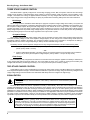
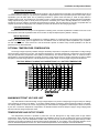
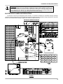
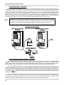
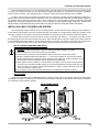
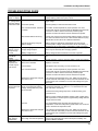
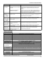
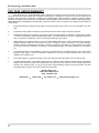
SOLAR BOOST™ 3024i 30AMP 12/24VDC MAXIMUM POWER POINT TRACKING PHOTOVOLTAIC CHARGE CONTROLLER INSTALLATION AND OPERATION MANUAL THIS MANUAL INCLUDES IMPORTANT SAFETY INSTRUCTIONS FOR MODELS SB3024i AND SB3024Di. SAVE THESE INSTRUCTIONS. COVERED UNDER ONE OR MORE OF THE FOLLOWING US PATENTS 6,111,391 • 6,204,645 © Blue Sky Energy, Inc. 2006 430-0018 E Blue Sky Energy - Solar Boost 3024i TABLE OF CONTENTS IMPORTANT SAFETY INSTRUCTIONS ............................................................................................ 2 PRODUCT DESCRIPTION ................................................................................................................. 3 Part Numbers and Options ................................................................................................... 3 OPERATION ....................................................................................................................................... 3 Optional Digital Display......................................................................................................... 3 Optional Remote Displays .................................................................................................... 3 Charge Status Indicator ........................................................................................................ 4 Three Stage Charge Control ................................................................................................. 5 Bulk Charge....................................................................................................... 5 Acceptance Charge........................................................................................... 5 Float Charge...................................................................................................... ..5 Two Stage Charge Control.................................................................................................... 5 Equalization .......................................................................................................................... 5 Equalize Time Accumulator............................................................................... 6 Automatic Equalization...................................................................................... 6 Manual Equalization .......................................................................................... 6 Optional Temperature Compensation................................................................................... 6 Maximum Setpoint Voltage Limit........................................................................................... 6 Temperature and Output Power............................................................................................ 6 Maximum Power Point Tracking (MPPT) .............................................................................. 7 How MPPT Works ............................................................................................. 7 Multiple Charge Controllers On The IPN Network................................................................. 7 INSTALLATION .................................................................................................................................. 7 Over Voltage / Reverse Polarity Protection........................................................................... 7 Electrostatic Handling Precautions ....................................................................................... 8 Solar Boost 3024i Setup ....................................................................................................... 9 Factory Default Settings .................................................................................... 9 Restoring Default Settings................................................................................. 9 Basic Settings ................................................................................................... 9 Advanced Settings ............................................................................................ 10 Battery And PV Voltage..................................................................................... 10 Charge Mode..................................................................................................... 10 Acceptance Charge Voltage.............................................................................. 10 Float Charge Voltage ........................................................................................ 10 Acceptance Charge Time.................................................................................. 11 IPN Network Address ........................................................................................ 11 Output Current Display...................................................................................... 11 Battery and PV Wiring .......................................................................................................... 11 24V Input / 12V Output ......................................................................................................... 12 Battery Temperature Sensor................................................................................................. 12 Auxiliary Output..................................................................................................................... 12 Auxiliary Battery Charge.................................................................................... 12 Load Controller.................................................................................................. 13 Dusk-to-Dawn Lighting Control ......................................................................... 13 Installing a Multi-Controller System ...................................................................................... 14 Multi-Controller Wiring And Setup..................................................................... 14 IPN Network ...................................................................................................... 14 Auxiliary Output In Multi-Controller Systems ..................................................... 15 Mounting ............................................................................................................................... 15 TROUBLESHOOTING GUIDE............................................................................................................ 16 SPECIFICATIONS .............................................................................................................................. 18 TWO YEAR LIMITED WARRANTY .................................................................................................... 19 TABLES AND FIGURES Table 1 Charge Status Indicator..................................................................................... 4 Table 2 Maximum Conductor Length - 3% Voltage Drop ............................................... 12 Figure 1 Front Panel and Remote Display Indicators...................................................... 4 Figure 2 Factory Charge Voltage Setpoint -vs.- Battery Temperature ............................ 6 Figure 3 Setup and Wiring Diagram ................................................................................ 8 Figure 4 Auxiliary Output Wiring...................................................................................... 13 Figure 5 IPN Network Wiring........................................................................................... 14 Figure 6 Detailed Dimensional Drawing .......................................................................... 15 1 Installation and Operation Manual IMPORTANT SAFETY INSTRUCTIONS This manual contains important instructions for Models SB3024i and SB3024Di SAVE THESE INSTRUCTIONS 1. Refer installation and servicing to qualified service personnel. High voltage is present inside unit. Incorrect installation or use may result in risk of electric shock or fire. No user serviceable parts in this unit. 2. To reduce the risk of electric shock, fire or personal injury, the following symbols are placed throughout this manual to indicate dangerous conditions, or important safety or operational instructions. WARNING CAUTION IMPORTANT Indicates dangerous conditions or electric shock potential. Use extreme caution. Indicates items critical to safe installation or operation of the unit. Follow these instructions closely for proper operation of the unit 3. PERSONAL PRECAUTIONS a) Working in the vicinity of lead-acid batteries is dangerous. Batteries produce explosive gasses during normal operation. b) To reduce risk of battery explosion, follow these instructions and those published by battery manufacturer and manufacturer of any equipment you intend to use in vicinity of battery. c) Someone should be within range of your voice or close enough to come to your aid when you work near a lead-acid battery. d) Have plenty of fresh water and soap nearby in case battery acid contacts skin, clothing or eyes. e) Wear complete eye protection and clothing protection. Avoid touching eyes while working near battery. f) If battery acid contacts skin or clothing, wash immediately with soap and water. If acid enters eye, immediately flood eye with running cold water for at least 10 minutes and get medical attention immediately. g) NEVER SMOKE or allow a spark or flame in vicinity of battery. h) Be extra cautious to reduce risk of dropping metal tool onto battery. It might spark or short circuit battery or other electrical part that may cause explosion. i) Remove personal metal items such as rings, bracelets and watches when working with a lead-acid battery. A lead-acid battery can produce a short circuit current high enough to weld a ring or the like to metal, causing a severe burn. j) Remove all sources of power, photovoltaic and battery before servicing or installing. 4. CHARGER LOCATION & INSTALLATION a) This unit is designed to charge flooded or sealed type lead-acid chemistry batteries. Follow battery manufacturers charging recommendations when considering this unit for use with other battery chemistry, i.e., NiCd. b) This unit employs components that tend to produce arcs or sparks. NEVER install in battery compartment or in the presence of explosive gases. c) This unit must be installed and wired in accordance with National Electrical Code, ANSI/NFPA 70. d) Over current protection for the battery must be provided externally. To reduce the risk of fire, connect to a circuit provided with 40 amperes maximum branch-circuit over current protection in accordance with National Electrical Code, ANSI/NFPA 70. e) Over current protection for the auxiliary load control output or auxiliary battery charge output must be provided externally. To reduce the risk of fire, connect to load or auxiliary battery with 25 amperes maximum over current protection in accordance with National Electrical Code, ANSI/NFPA 70. f) Insure that unit is properly configured for the battery being charged. g) Unit is not water tight. Do not expose to rain or snow. h) Insure all terminating connections are clean and tight. Battery and PV compression terminals are to be tightened to 45 in-lb (5 nm). IPN Network and battery temperature sensor compression terminals are to be tightened to 2.1 in-lb (0.24 nm). Auxiliary output compression terminals are to be tightened to 6 in-lb (0.67 nm). i) Charging system must be properly installed as described in these instructions prior to operation. j) Do not connect to a PV array capable of producing greater than 24 amps of short circuit current at STC. Limit input short circuit current to 12 amps if the 24V input 12V output mode is used. 5. PREPARING TO CHARGE a) Never charge a frozen battery. b) Be sure battery is mounted in a well ventilated compartment. c) Add distilled water in each cell of a lead-acid battery until battery acid reaches level specified by battery manufacturer. This helps purge excessive gas from the cells. Do not overfill. For batteries other than flooded lead-acid type, or sealed batteries without cell caps, carefully follow manufacturers charging instructions. 2 Blue Sky Energy - Solar Boost 3024i PRODUCT DESCRIPTION Solar Boost™ 3024i a 30 amp 12/24 volt Maximum Power Point Tracking (MPPT) photovoltaic (PV) battery charge controller. Through the use of patented MPPT technology, Solar Boost 3024i can increase charge current up to 30% or more compared to conventional controllers. Solar Boost 3024i’s sophisticated three stage charge control system can be configured to optimize charge parameters to precise battery requirements. The unit is fully protected against voltage transients, over temperature, over current, reverse battery and reverse PV connections. An automatic current limit feature allows use of the full 30 amp capability without worrying about overload or nuisance fuse blow from excessive current. A versatile auxiliary output can provide either a 2 amp battery charger for a second battery, voltage or amp-hour based load control, or variable Dusk-to-Dawn lighting control. Series pass Pulse Width Modulation (PWM) charge voltage control combined with a multistage charge control algorithm leads to superior charging and enhanced battery performance. The filtered PWM power control system uses highly efficient and reliable power MOSFET transistors. The MOSFET’s are turned on and off at high frequency to precisely control charge voltage and MPPT. An environmentally sealed high current high reliability relay is used to disconnect the PV array at night to prevent unwanted current drain. A relay is used rather than blocking diodes for improved power conversion efficiency, current boost performance, and true reverse battery polarity protection in an MPPT controller. Fully automatic temperature compensation of charge voltage is available to further improve charge control and battery performance. The optional battery temperature sensor is built for long term reliability. The sensor element is environmentally sealed and encapsulated into a copper lug which mounts directly to the battery terminal. The Solar Boost 3024i also includes an IPN Network interface. The IPN interface allows multiple IPN compatible charge controllers to communicate with each other and operate as a single machine rather than separate charge controllers. The IPN interface also provides connection to optional IPN compatible remote displays. The full featured IPN-ProRemote provides enhanced charge controller setup, monitoring and control. It also provides a complete battery system monitor with amp-hour counting and a highly accurate remaining battery capacity “fuel gage” type indicator. PART NUMBERS AND OPTIONS • • • • • • SB3024i...............................Solar Boost 3024i controller SB3024Di ............................Solar Boost 3024i controller with volt/amp digital display IPNREMOTE.......................IPN-Remote, Low cost LED Bargraph IPN charge control monitor w/25’ cable IPNPRO ..............................IPN-ProRemote, Full featured IPN charge control and battery system monitor w/25’ cable IPNPRO-S...........................IPN-ProRemote with 500A/50mV current shunt CS-500 ................................500A/50mV current shunt OPERATION Once installed and configured, charge control and MPPT operations are fully automatic. Charge turns on whenever the PV array is capable of producing ≈0.1 amps at battery voltage. When PV charge is on the Charge Status LED will indicate the present charge mode, and indicate when the battery has become highly charged. At night when PV power production stops, the PV array is disconnected from the battery to prevent unwanted current drain. Note that there is a 5 second turn-on delay, and a 45 second turn-off delay. ¾ The unit operates on battery power, not PV power. A battery must be connected with a minimum voltage of 9V for the unit to operate. OPTIONAL DIGITAL DISPLAY The digital display provided in the Solar Boost 3024Di shows battery voltage and output charge current. A low power LED display is used to provide both very low power consumption (≈0.15W) and excellent readability. Battery voltage is continuously displayed when the charge controller it not charging the battery. Once the charge controller turns on and begins charging the battery the display will alternate between battery voltage and charger output current, each shown for 3 seconds. The display can show readings of up to 99.9 volts or amps maximum. Readings greater than 99.9 will display as 99.9. The output charge current shown can be set to either the total output charge current of all charge controllers on the IPN network (factory default), or the output charge current of a particular charge controller on the IPN network OPTIONAL REMOTE DISPLAYS Solar Boost 3024i and 3024Di include an IPN interface which allows for a variety of display options. There are two available remote displays, the very low cost IPN-Remote and the full featured IPN-ProRemote. The IPN-Remote is a basic three digit 3 Installation and Operation Manual battery voltage and output current display without setup or control capability. It uses the same display circuit board as the display in the Solar Boost 3024Di. The full featured IPN-ProRemote incorporates a multi-line backlit LCD display and three function keys to provide enhanced setup and monitoring of IPN devices on an IPN network. The IPN-ProRemote provides the ability to access additional setup parameters and adjust setup parameters to wider ranges that those available with the Solar Boost 3024i alone. The IPN-ProRemote also provides complete battery system monitoring and eliminates the need for a separate battery monitor. Some of the many display features include; battery voltage, net battery current, net battery amp-hours, highly accurate battery capacity “fuel gage”, PV amp-hours, min/max battery voltage, auxiliary battery voltage, load control status and much more. With the IPN-ProRemote, the Solar Boost 3024i can be configured to determine the end-of-charge based on net battery current matched to battery capacity in amp-hours to provide the most highly optimized charge process. FRONT PANEL AND REMOTE DISPLAY INDICATORS FIGURE 1 CHARGE STATUS INDICATOR An LED charge status indicator is provided on the face of the unit, and on the IPN-Remote and IPN-ProRemote displays. The LED will be off when the unit is not charging, and will be on solid or blinking when the unit is charging the battery. If the PV array is capable of delivering greater than approximately 3 to 5 amps per 100 amp-hours of battery capacity, the charge status LED can provide a rough approximation of battery state of charge as shown in the table below. CHARGE STATUS INDICATOR STATUS LED CHARGE MODE APPROXIMATE CHARGE LEVEL OFF [0] CHARGE OFF NOT DISPLAYED CONTINUOUSLY ON [1] BULK <70% FULL BLINKING 1 SEC ON [1] / 1 SEC OFF [0] ACCEPTANCE 70% - 95% FULL BLINKING 0.2 SEC ON [1] / 1 SEC OFF [0] FLOAT FULLY CHARGED BLINKING RAPIDLY 0.2 SEC ON [1] / 0.2 SEC OFF [0] EQUALIZE TABLE 1 4 Blue Sky Energy - Solar Boost 3024i THREE STAGE CHARGE CONTROL Solar Boost 3024i is typically configured for a three stage charging process, Bulk, Acceptance and Float. The three stage charge process provides a somewhat higher charge voltage to charge the battery quickly and safely. Once the battery is fully charged a somewhat lower voltage is applied maintain the battery in a fully charged state without excessive water loss. The three stage charge process charges the battery as quickly as possible while minimizing battery water loss and maintenance. Bulk Charge When charge starts the Solar Boost 3024i attempts to apply the Acceptance charge voltage to the battery. The system will switch to Bulk charge if the battery is sufficiently discharged and/or insufficient charge current is available to drive the battery up to the Acceptance voltage setpoint. During the Bulk charge stage the unit delivers as much charge current as possible to rapidly recharge the battery. Once the charge control system enters Acceptance or Float, the unit will again switch to Bulk charge if battery voltage drops below the present charge voltage setpoint. Fully automatic electronic current limit prevents the possibility of overload by limiting output current to 30 amps regardless of PV input current or power. Acceptance Charge As the battery charges in Bulk, battery voltage slowly rises as the battery recovers charge. When sufficient charge has been recovered for battery voltage to reach the Acceptance voltage setpoint, the unit changes to a constant voltage mode where the Acceptance voltage is applied to the battery. The Acceptance voltage is factory set to 14.4/28.8V. In Acceptance the battery is typically between 70% to 95% charged depending on battery size and available charge current. The battery remains at the Acceptance voltage until it is fully charged and switches to Float as determined by either; 1. Battery voltage has been continuously at (or above) the Acceptance voltage setpoint for the Charge Time period. (factory default = 2 hours) – OR – 2. With the IPN-ProRemote display, net battery charge current drops below the Float Transition Current while the battery is at (or above) the Acceptance voltage setpoint. (factory default = 1.5A per 100 amp-hours) Float Charge Once the battery is fully charged the unit switches to Float where the Float voltage is applied to the battery to maintain it in a fully charged state without excessive water loss. The Float voltage is factory set to 13.2/26.4V. During Float a healthy fully charged lead-acid battery will draw approximately 0.1–0.2 amps per 100 amp-hours of battery capacity. TWO STAGE CHARGE CONTROL Certain battery types or system configurations may require two stage charge control. Solar Boost 3024i can be configured for a two stage bulk-acceptance charge to accommodate these batteries or systems. Two stage charge is selected by setting the Float charge voltage setting to No Float. Refer to the Solar Boost 3024i Setup section to configure two stage charge. EQUALIZATION ¾ WARNING: Not all batteries can be safely equalized. Equalization should only be performed on vented liquid electrolyte lead-acid batteries. Follow battery manufacturers recommendations pertaining to equalization. The Solar Boost 3024i can perform equalization manually or automatically. Since each cell of a battery is not identical, repeated charge/discharge cycles can lead to an imbalance in the specific gravity of individual cells and electrolyte stratification. Equalization is essentially a controlled overcharge which brings all battery cells up to the same specific gravity and eliminates stratification by heavily gassing the battery. While equalization parameters are adjustable with the IPN-ProRemote, factory default parameters of 15.2/30.4V for 2 hours every 30 days are suitable for most applications. Note that for proper equalization a minimum net charge current of approximately 3 amps per 100 amp-hours of battery capacity is required. If insufficient current is available equalization may have to be canceled manually since the equalization time accumulator may not be able to complete count down. ¾ CAUTION: Equalization is a controlled over charge of the battery at a relatively high voltage producing heavy battery gassing. While the Solar Boost 3024i can be configured for manual or automatic equalization it is strongly recommended that a qualified operator always plan and monitor the process. The operator should ensure that connected equipment can tolerate the high equalization voltage which is factory set to 15.2/30.4V. Since the Equalization voltage is temperature compensated, the voltage can be quite high at cool temperatures if temperature compensation is used. 5 Installation and Operation Manual Equalize Time Accumulator The equalize time period is not a simple timer but rather a “time at voltage” time accumulator. The equalization timer will not count down unless the battery is at (or above) the equalization voltage setpoint for the required time period to assure that a proper equalization cycle has taken place. This is particularly beneficial on systems where the battery or loads are large relative to available charge current. The equalize time accumulator counts in 3 minute increments. If battery voltage reached the equalization voltage setpoint during a given 3 minute period, that period is considered good. Unless manually disabled, the unit will stay in equalize for as long as it takes to accumulate the required time at voltage. This may take hours or even days. If equalize does not complete by the time the charging day ends, it will pick up where it left off when the next charging day begins. Automatic Equalization If DIP switch #5 is turned ON prior to the application of battery power, automatic equalization is enabled. From then on the unit will perform automatic equalization after the set number of days has elapsed (factory default = 30 days). Manual Equalization If DIP switch #5 is turned OFF, equalization is completely disabled. A manual equalize can be performed by turning DIP switch #5 ON, after battery power is applied and the unit initializes. After the manually initiated equalization cycle completes, turn DIP switch #5 OFF. If DIP switch #5 is left ON automatic equalize is enabled. Fully manual equalization can also be performed from the IPN-ProRemote. OPTIONAL TEMPERATURE COMPENSATION The charge voltage required by batteries changes with battery temperature. Temperature compensation of charge voltage enhances battery performance and life, and decreases maintenance. Automatic temperature compensation can be provided using the optional battery temperature sensor (BSE p/n 930-0022-20). The default compensation factor of –5.00mV/°C/cell is appropriate for most lead-acid batteries. The graph of Figure 2 shows charge voltage vs. battery temperature for factory default Acceptance and Float voltage setpoints. The temperature compensation factor can be changed using the IPN-ProRemote. FACTORY DEFAULT CHARGE VOLTAGE SETPOINT -VS.- BATTERY TEMPERATURE FIGURE 2 MAXIMUM SETPOINT VOLTAGE LIMIT Very cold batteries combined with high charge voltage setpoints can produce voltages high enough to disrupt or damage other equipment connected to the battery. To minimize possible damage a maximum voltage setpoint limit feature is provided. The factory defaults of 15.5/31.0V can be changed using the IPN-ProRemote. Regardless of what setpoint values are entered by the user or result from temperature compensation, the Solar Boost 3024i will never attempt to apply a charge voltage greater than the maximum voltage setpoint limit value. TEMPERATURE AND OUTPUT POWER Over temperature protection is provided to protect the unit from damage due to high output power at high ambient temperatures. When mounted vertically as described in the installation section, the unit can deliver full output in a temperature of up to 40°C (104°F). If an over temperature condition exists, the unit will cycle on/off, reducing average power delivery to within safe limits. During thermal shutdown the Charge Status Indicator will display an “off” condition. Over temperature shutdown occurs when the heatsink temperature reaches 75°C. Actual heatsink temperature for can be displayed on the IPN-ProRemote. 6 Blue Sky Energy - Solar Boost 3024i MAXIMUM POWER POINT TRACKING (MPPT) MPPT and associated current boost operation is fully automatic and will function whenever sufficient PV voltage and current are available. The percent increase in output charge current relative to PV current is variable, and will change with operating conditions. When conditions are such that insufficient PV power is available to produce an increase in output current, the unit will stop it’s internal DC-DC power conversion and operate as a series pass PWM controller with very low forward voltage drop. The principal operating conditions which affect current boost performance are PV array temperature and battery voltage. At constant solar intensity available PV power changes with PV temperature. A PV array’s power vs. temperature characteristic is such that a cool PV array can produce a higher voltage and more power, than a hot PV array. When PV voltage is sufficiently high for MPPT to operate, a constant power output is delivered to the battery. Since output power is constant while MPPT is operating, a decrease in battery voltage produces corresponding increase in charge current. This means that the greatest current increase occurs with a combination of cool ambient temperature and low battery voltage. The unit delivers the greatest charge current increase when you need it most, in cold weather with a discharged battery. Additionally, anything that can be done to lower PV array temperature will also lead to increased charge current by increasing PV power production. In cool/comfortable temperatures and typical battery states of charge, most systems see about 10 – 20% increase. Charge current increase can go to zero in hot temperatures, whereas charge current increase can easily exceed 30% with a discharged battery and freezing temperatures. HOW MPPT WORKS A PV module is a constant current type device. As shown on a typical PV module voltage vs. current curve, current remains relatively constant over a wide range of voltage. A typical 75 watt module is specified to deliver 4.45 amps @ 17 volts @ 25°C cell temperature. Conventional PV controllers essentially connect the PV array directly to the battery when battery is discharged. When a 75 watt module is connected directly to a battery charging at 12 volts, the module still provides approximately the same current. But, because output voltage is now at 12 volts rather than 17 volts, module power production is artificially limited and the 75W module only delivers 53 watts. This wastes 22 watts of available power. Solar Boost 3024i’s patented MPPT technology operates in a very different fashion. Under these conditions Solar Boost 3024i calculates the maximum power voltage (VMP) at which the PV module delivers maximum power, in this case 17 volts. It then operates the module 17 volts which extracts maximum available power from the module. Solar Boost 3024i continually recalculates the maximum power voltage as operating conditions change. Input power from the maximum power tracking controller, in this case 75 watts, feeds a switching type power converter which reduces the 17 volt input to battery voltage at the output. The full 75 watts which is now being delivered at 12 volts would produce a current of 6.25 amps. A charge current increase of 1.8 amps or 40% is achieved by converting the 22 watts that would have been wasted into useable charge current. Note that this example assumes 100% efficiency to illustrate the principal of operation. In actual operation, boost will be somewhat less. MULTIPLE CHARGE CONTROLLERS ON THE IPN NETWORK A key advantage of the IPN network architecture is the ability for multiple charge controllers operate as a single machine. Up to 8 IPN compatible charge controllers can reside on a single IPN network charging a common battery. An single optional display monitors all chargers on the network, and a single battery temperature sensor serves all chargers on the network and temperature related functions of the IPN-ProRemote. Charge controllers can be added to grow a small system into a large system and have this large system operate from the users standpoint as a single large charge controller. If any charge controller in a multi controller system has input power available, the charge control system will start and charge the battery based on charge control parameters set in the master. INSTALLATION ¾ WARNING: Read, understand and follow the Important Safety Instructions in the beginning of this manual before proceeding. Do not connect a PV array capable of delivering greater than 24A of short circuit current (ISC) at STC, which equates to roughly 400W or 800W of PV power into a 12V or 24V battery respectively. To reduce the risk of fire, connect only to a circuit provided with 40 amperes maximum branch-circuit over current protection. Product must be installed and wired in accordance with National Electrical Code, ANSI/NFPA 70. To reduce risk of electric shock, remove all sources of power, PV and battery before installing or servicing. Adjustments or connections other than those shown in Figures 3, 4 and 5 void the limited warranty. Figures 3, 4 and 5 show generalized connections only and are not intended to show all wiring, circuit protection and safety requirements for a photovoltaic electrical system. OVER VOLTAGE / REVERSE POLARITY PROTECTION Solar Boost 3024i is fully protected against reverse polarity and high voltage transients for both the PV and the battery connections. If the battery is connected reverse polarity, Solar Boost 3024i will not operate. If the PV array is connected reverse polarity the charge control system will not turn on or provide output current. Should high PV current be available during reverse PV connection the heatsink will become quite warm but no damage to the unit will result. 7 Installation and Operation Manual ¾ CAUTION: The unit is protected against reverse battery and reverse PV polarity, but is not protected against reverse battery to the PV terminals. Additionally, transient voltage protection devices on the battery and PV terminals are designed to absorb static electric discharges, or other high voltage transients and can dissipate up to 1.5KW for 1ms. Steady state voltage in excess of 57V on either the battery or PV terminals will damage the unit. Damage of this type will void the limited warranty. ELECTROSTATIC HANDLING PRECAUTIONS All electronic circuits may be damaged by static electricity. To minimize the likelihood of electrostatic damage, discharge yourself by touching a water faucet or other electrical ground prior to handling the unit and avoid touching components on the circuit boards. The risk of electrostatic damage is highest when relative humidity is below 40%. SETUP AND WIRING DIAGRAM FIGURE 3 8 Blue Sky Energy - Solar Boost 3024i SOLAR BOOST 3024i SETUP ¾ Solar Boost 3024i has various setup parameters all of which are preconfigured at the factory. Default settings are typically suitable for most flooded lead-acid batteries. Most installations require no changes other than configuring the Auxiliary Output if used, and enabling Equalization if desired. -------------------------------------------------------------------¾ Setup parameters are divided into two categories, Basic and Advanced. Basic parameters can be configured with the Solar Boost 3024i alone within limited ranges. Advanced parameters require the IPNProRemote to access and change. All parameters are retained if power is lost or the IPN-ProRemote is used as a setup tool only and removed. Factory Default Settings Basic Settings • Charge mode ................................ • Acceptance voltage ....................... • Float voltage .................................. • Charge time ................................... • Equalize.......................................... • IPN Network address .................... • Auxiliary Output mode ................... • All DIP switches ............................. 3 stage 14.4/28.8V 13.2/26.4V 2.0 hours Disabled 0 (zero) Aux. bat. charger Physically set to OFF Advanced Settings • Equalize voltage ........................................ 15.2/30.4V • Equalize time ............................................. 2.0 hours • Auto equalize days .................................... 30 days • Maximum voltage setpoint limit ................. 15.5/31.0V • Float Transition Current ............................. 1.5A/100 amp-hours • Temperature compensation factor ............ -5.00mV/°C/cell • Load control ON voltage ......................... . 12.6/25.2V • Load control OFF voltage........................ . 11.5/23.0V • Dusk-to-Dawn lighting control ................. . Disabled Restoring Factory Default Settings Factory defaults can be easily restored into the Solar Boost 3024i. If the unit is not received in a factory sealed package, it is possible that settings may not be set to factory defaults. If there is any doubt about present settings, restoring defaults is highly recommended. Note that restoring defaults as described here restores all defaults in the Solar Boost 3024i but does not restore defaults in IPN-ProRemote. See the IPN-ProRemote operators manual regarding it’s restore defaults function. To restore Solar Boost 3024i factory defaults: 1. Remove PV and battery power. 2. Turn ALL 8 DIP switches shown in Figure 3 ON. 3. Restore battery power, wait at least 10 seconds, then remove battery power. 4. Return ALL 8 DIP switches to their default OFF position. 5. The unit is now configured to factory default settings. Basic Settings These setup options are configured with a single 8 position DIP switch located on the main circuit board as shown in Figure 3. All parameters are saved by switch position or in non-volatile memory and are retained if power is lost. 9 PARAMETER OR FUNCTION Acceptance Charge Voltage (VCHG) Float Charge Voltage (VFLOT) Charge Time (TCHG) Auxiliary Output FACTORY DEFAULT 14.4V* Aux. Battery Charge Auto Equalize Enable Disabled Output current display (SB3024Di) IPN Address Total output of all IPN charge controllers 0 (zero) 13.2V* 2.0 Hrs RANGE WITH SB3024i ALONE 14.0 – 14.8V* (0.2V steps)* 13.2 – 13.8V* (0.2V steps)* 0.0 – 4.0 Hrs (1.0 Hr steps) Aux. Battery Charge -or- Load Controller Enabled / Disabled -or- Manual 0–7 Plus IPN total 0–7 RANGE WITH IPN-ProRemote 10.0 – 40.0V 10.0 – 40.0V 0.0 – 10.0 Hrs (0.5 Hr steps) Remote Monitoring Only Remote Monitoring -and- Manual on/off – – *Double for 24V battery Installation and Operation Manual Advanced Settings Advanced settings are programmed into the Solar Boost 3024i and are suitable for most installations. Advanced parameters can be changed only with the IPN-ProRemote display. All advanced parameters are saved in non-volatile memory and are retained if power is lost or IPN-ProRemote is permanently removed. PARAMETER OR FUNCTION Auto Equalize Days FACTORY DEFAULT 30 days Equalize Voltage 15.2V* Equalize Time 2.0 Hrs RANGE VIA IPN-ProRemote 10 – 400 days (5 day steps) -or- Manual 10.0 – 40.0V (0.1V steps) 0.5 – 10.0 Hrs (0.5Hr steps) Load Control Low Voltage Disconnect ON ≥12.6V* OFF ≤11.5V* ON/OFF 10.0 – 40.0V -orBased on net battery amp-hours (5AH steps) Dusk-to-Dawn lighting control Disabled Time at charge voltage (TCHG) Post-Dusk and/or Pre-Dawn ON time 0.0 – 20.0 hours (0.5 hours steps) Time at charge voltage (TCHG) -or- net battery charge current matched to battery amp-hours -0.00 – -8.00mV/°C/cell (0.05mV/°C/cell steps) 10.0 – 40.0V (0.1V steps) *Double for 24V battery ⎯ End Of Charge Determination Temperature Compensation Factor Maximum voltage setpoint limit -5.00mV/°C/cell 15.5V* ⎯ Battery and PV Voltage ¾ WARNING: Battery and PV voltage are determined automatically. Be certain battery is sufficiently charged and connected quickly to allow proper battery voltage determination. The battery is determined to be 12V if voltage when first connected is less than 18V, or 24V if battery voltage is greater. PV voltage is also determined automatically. PV voltage is determined to be 12V if always less than 30V, or 24V if ever greater. If PV type is changed from 24V to 12V following installation, battery and PV power must be momentarily removed and restored so that proper PV voltage can again be determined. Charge Mode Solar Boost 3024i is typically configured for three stage charge. Certain battery types or system configurations may benefit from two stage constant voltage charge. Two stage charge is selected by setting the Float voltage setting to one step below it’s minimum voltage setting. “No Float” will then be displayed and the unit will never switch to the Float charge stage. Acceptance Charge Voltage The factory Acceptance charge voltage setting of 14.4/28.8V is suitable for most lead-acid batteries. The setting can be viewed or changed using the charge parameter setup LED’s and operating mode DIP switch shown in Figure 3. To view the present setting, turn the VCHG switch #8 ON momentarily. If more than one value LED lights, the present setting is in-between these values. If no value LED’s light, the present setting is outside the range than can be shown. For a 24V battery the actual setpoint is double that shown on the LED’s. To change the setting, turn the VCHG switch ON, OFF and then back ON before the LED’s turn OFF. The unit will enter the setup mode and scan through available settings. Turn the VCHG switch off at the desired setting to store the new value. The LED’s will blink several times to show the new value was accepted and stored. Float Charge Voltage The factory Float charge voltage setting of 13.2/26.4V is suitable for most lead-acid batteries. The setting can be viewed or changed using the charge parameter setup LED’s and operating mode DIP switch shown in Figure 3. To view the present setting, turn the VFLOT switch #6 ON momentarily. If more than one value LED lights, the present setting is in-between these values. If no value LED’s light, the present setting is outside the range than can be shown. For a 24V battery the actual setpoint is double that shown on the LED’s. To change the setting, turn the VFLOAT switch ON, OFF and then back ON before the LED’s turn OFF. The unit will enter the setup mode and scan through available settings. Turn the VFLOT switch off at the desired setting to store the new value. The LED’s will blink several times to show the new value was accepted and stored. 10 Blue Sky Energy - Solar Boost 3024i Acceptance Charge Time Once the battery recovers sufficient charge to reach the Acceptance charge voltage setpoint, it will remain at this voltage for the Charge Time period, and then the unit will switch to Float. The default Charge Time setting of 2.0 hours is suitable for most lead-acid batteries. The setting can be viewed or changed using the charge parameter setup LED’s and operating mode DIP switch shown in Figure 3. To view the present setting, turn the TCHG switch #7 ON momentarily. If more than one value LED lights, the present setting is in-between these values. If no value LED’s light, the present setting is outside the range than can be shown. To change the setting, turn the TCHG switch ON, OFF and then back ON before the LED’s turn OFF. The unit will enter the setup mode and scan through available settings. Turn the TCHG switch off at the desired setting to store the new value. The LED’s will blink several times to show the new value was accepted and stored. IPN Network Address ¾ A single controller must have it’s IPN network address set to 0 (zero), which is the factory default. In a multi-controller system one (and only one) controller must have it’s IPN network address set to 0 (zero) to serve as the network and charge control master. The other controllers can be any other address (1-7), but no controller can have the same address. DIP SWITCH # 1 (A2) # 2 (A1) # 3 (A0) MASTER 0 OFF OFF OFF IPN NETWORK ADDRESS SLAVES 1 2 3 4 OFF OFF OFF ON OFF ON ON OFF ON OFF ON OFF 5 ON OFF ON 6 ON ON OFF 7 ON ON ON Output Current Display (SB3024Di only) ¾ While the display plugs into the connector of a particular unit it has access to the entire IPN network and can display the total output current from all controllers on the network, or the output current of a particular controller. If more than one charge controller is present on the IPN network and it is desired to have the display show only the output current from that controller, the IPN network address of the display must match the IPN address of the charge controller it is intended to monitor. A four position DIP switch on the display circuit board configures the output current display. The factory default setting of total output current from all charge controllers on the IPN network is suitable for both a single charge controller, or multiple charge controllers if only one controller has a display. DISPLAY DIP SWITCH # 1 (A2) # 2 (A1) # 3 (A0) # 4 (IPN Total) IPN ADDRESS – OUTPUT CURRENT OF SINGLE CHARGER UNIT 0 1 2 3 4 5 6 7 OFF OFF OFF OFF OFF OFF ON OFF OFF ON OFF OFF OFF ON ON OFF ON OFF OFF OFF ON OFF ON OFF ON ON OFF OFF ON ON ON OFF TOTAL OUTPUT CURRENT OF ALL CHARGERS ON IPN NETWORK Don’t care Don’t care Don’t care ON BATTERY AND PV WIRING ¾ WARNING: This unit must be installed and wired in accordance with National Electrical Code, ANSI/NFPA 70. Over current protection for the battery must be provided externally. To reduce the risk of fire, connect to a circuit provided with 40 amperes maximum branch-circuit over current protection in accordance with National Electrical Code, ANSI/NFPA 70. Figures 3, 4 and 5 show generalized wiring information only and do not include all wiring and safety requirements for a photovoltaic electrical system. ¾ CAUTION: Battery and PV compression terminals accept #14−4 AWG wire and are to be tightened to 45 in-lb (5 nm). IPN network compression terminals accept #24−14 AWG wire and are to be tightened to 2.1 in-lb (0.24 nm). Auxiliary Output compression terminals accept #24−12 AWG wire and are to be tightened to 6 in-lb (0.67 nm). -------------------------------------------------------------------¾ CAUTION: DO NOT connect Bat– and PV– together outside of the unit or improper operation will result. Bat– and PV– connect together internally. 11 Installation and Operation Manual Wiring requirements for Solar Boost 3024i are somewhat different than conventional PV controllers. While the performance of other controllers may be affected somewhat by wiring, wiring and connections used with this unit can have a significant effect on current boost performance. The effect wiring has on current boost performance is that PV power wasted heating undersized wires or poor connections becomes unavailable to charge the battery. A desirable installation would produce a total system wiring voltage drop of 3% or less. Table 2 is meant to serve as a wire size guide which will lead to good boost performance with reasonable wire sizes. The lengths shown are one way for the wire pair between the PV array and battery. Larger wire sizes will tend to improve boost performance whereas smaller wire sizes will reduce boost performance. MAXIMUM CONDUCTOR PAIR LENGTH - 3% VOLTAGE DROP WIRE GAUGE AWG 12 AWG 10 AWG 8 AWG 6 AWG 4 AWG 2 AWG 1/0 AWG 12 VOLT SYSTEM @24AMPS FEET / METERS 5.3 / 1.6 8.5 / 2.6 13.5 / 4.1 21.4 / 6.5 34.0 / 10.4 54.1 / 16.5 86.1 / 26.3 24 VOLT SYSTEM @24AMPS FEET / METERS 10.7 / 3.3 16.9 / 5.2 26.9 / 8.2 42.8 / 13.0 68.1 / 20.7 108.2 / 33.0 172.2 / 52.5 TABLE 2 24V INPUT / 12V OUTPUT It is possible to wire the PV array for 24V and charge a 12V battery. In this 12/24V operating mode a minimum PV input current of approximately 0.3 amp is required for MPPT to operate and PV voltage to rise the desired operating point. When MPPT operates, output charge current will be approximately 2X or more PV input current. While best overall power delivery efficiency is generally achieved with like input/output voltage this special operating mode can be quite useful for 12 volt systems with long PV wiring lengths. Wire length can be four times as long for a given wire size by doubling input voltage and halving input current. This operating mode can also solve problems associated with very high temperature operation where conventional controllers cease to deliver current due to temperature induced PV voltage reduction. In this mode input current (ISC at STC) should be limited to 12 amps since 12 amps of input current will produce approximately 24 amps of output current. BATTERY TEMPERATURE SENSOR Simply connecting the optional battery temperature sensor as shown in Figure 3 will enable temperature compensation of all charge voltage setpoints, and enable all other battery temperature related functions. While the copper lug containing the sensor element has no electrical connection it is recommended that the sensor be connected to a negative battery terminal. Sensor temperature can be displayed directly on the IPN-ProRemote, or sensor voltage can be used confirm operation. With the sensor connected it’s voltage should read approximately 2.98V at 25°C and change by +10mV/°C. If the sensor open, short, installed reverse polarity or missing, all temperature related functions will operate as if the sensor was at 25°C. ¾ In a multi-controller system only one (1) the temperature sensor is required and must connect to the master (IPN address zero [0]). The master then shares temperature information with all other devices on the IPN network. AUXILIARY OUTPUT The auxiliary output can serve one of three separate functions, either a 2 amp auxiliary battery charger, a 20 amp load controller, or a 20A variable Dusk-to-Dawn lighting controller. It cannot perform more than one of these functions at a time. The Charge/Load function is selected by DIP switch #4 as shown in Figure 3. The IPN-ProRemote is required as a setup tool adjust Load Control thresholds or enable Dusk-to-Dawn lighting load control. The auxiliary output LED will illuminate whenever the auxiliary output is ON. ¾ CAUTION: The auxiliary output cannot perform both auxiliary battery charge and load control functions at the same time. AUXILIARY BATTERY CHARGE – DIP #4 OFF The auxiliary charge function is used to charge a separate battery of the same voltage as the primary battery. Control is such that the primary battery is first priority and the auxiliary battery is second priority. If charge is off or the primary battery is in Bulk, no power is diverted to the auxiliary battery. If the primary battery is in Acceptance or Float meaning the primary battery does not need all available power, up to 2 amps is diverted to the auxiliary battery at roughly the same charge voltage as the primary battery. Auxiliary battery voltage can be displayed on the IPN-ProRemote. Auxiliary battery charge is disabled during equalization. 12 Blue Sky Energy - Solar Boost 3024i LOAD CONTROLLER – DIP #4 ON The load control feature can deliver up to 20 amps and controls ON/OFF based on battery voltage. If the IPN-ProRemote is used ON/OFF switching can be based on net battery amp-hours. Factory default settings are for Low Voltage Disconnect (LVD) operation with ON at VBAT ≥12.6/25.2V, and OFF at VBAT ≤11.5/23.0V. These values can be changed using the IPN-ProRemote. The ON/OFF condition must be valid for 20 seconds before switching will occur. The only constraint is that the ON/OFF values cannot be set the same. For normal LVD operation the OFF threshold is set to a lower value than the ON threshold. If the higher/lower values are reversed, the output control logic is inverted. For example a low voltage alarm can be created by setting ON to ≤11.5V, and OFF to ≥11.6V. The output will turn on to activate an alarm when battery voltage drops to 11.5V or less, and turn off when battery voltage climbs to 11.6V or more. This output invert capability applies to amp-hour control as well. ¾ If load controller output is configured to operate based on net battery amp-hours with the IPNProRemote, it is very important to set ON/OFF voltage thresholds as well. If a valid amp-hour reading is not available, load control operation will revert to voltage based operation. This will occur if the amp-hour counter has not been initialized by fully charging the battery, or the IPN-ProRemote is not present. -------------------------------------------------------------------¾ Voltage or amp-hour ON/OFF thresholds must not be the same values or improper operation will result. AUXILIARY OUTPUT WIRING FIGURE 4 DUSK-TO-DAWN LIGHTING CONTROL – DIP #4 ON With the auxiliary output configured for load control via DIP #4 it is also possible for the auxiliary output to provide variable timing Dusk-to-Dawn lighting control if the Solar Boost 3024i contains software version V2.00 or later. An IPN-ProRemote with software version V2.00 or later is required to setup and enable Dusk-to-Dawn lighting control. The following describes Dusk-toDawn functionality, while the IPN-ProRemote operators manual contains setup instructions for Dusk-to-Dawn parameters. Variable time settings are available to turn lighting ON after Dusk (Post-Dusk timer) and/or ON before Dawn (Pre-Dawn timer). If both the Post-Dusk and Pre-Dawn timers are set to DISABLED (factory default), the lighting control feature is disabled and the auxiliary output load controller operates based on battery voltage or amp-hours only. If either the Post-Dusk or Pre-Dawn timers are set to a time value (i.e., not DISABLED), the lighting control feature is enabled. When lighting control is enabled the auxiliary output is controlled by both the normal load control function and the lighting control function such that whichever function wants the auxiliary output OFF prevails. Dusk or the beginning of night time begins when the charge control system turns OFF due to insufficient sunlight which occurs when the PV module is no longer able to produce ≈50mA of output current at battery voltage. Dawn or the beginning of day time begins when the charge control system turns ON which occurs when the PV module is able to produce ≈100mA of output current at battery voltage. Lights will always be OFF during the day when the charge control system is ON. 13 Installation and Operation Manual If the Post-Dusk timer was set to 1.0 hour and the Pre-Dawn timer was set to 2.0 hours, lights would turn on at Dusk, remain on for one hour, and then turn OFF. Two hours before Dawn the lights would again turn on and remain on until Dawn. If full Duskto-Dawn ON time is desired, set the Post-Dusk timer to it’s maximum (20.0 hours) and the Pre-Dawn timer to disabled. Pre-Dawn control is based on predicting when Dawn will occur. When the controller first boots following the application of battery power it does not know when Dawn is expected to occur. As a result Pre-Dawn control does not initially operate, typically for the first night. Once a night time period of 4 hours or more is detected this night time period is stored and Pre-Dawn control will operate. Each subsequent night time period greater 4 hours is added to a running filtered average of night time. The filter slows abrupt changes in the predicted night time period but allows the night time period to change with seasons and weather. INSTALLING A MULTI-CONTROLLER SYSTEM Up to 8 IPN based charge controllers can be connected together in a multi-controller system charging a common battery. In an IPN based multi-controller system the controllers will setup and operate as a single machine rather than separate charge controllers. A display or other special communication hardware is not required for a multi-controller IPN network to operate. The basic control scheme is that device address 0 (zero) is the master and devices 1 – 7 are slaves. The master controls the charging process and directs the activities of the slaves. Each controller will be in the same charge mode and the system as a whole will charge the battery based on charge parameter setup in the master. The charge control system will start whenever one or more devices has input power, but only those devices with input power will have their Charge Status LED’s on. MULTI-CONTROLLER WIRING AND SETUP ¾ CAUTION: A multi-controller system requires the following specialized installation and setup: 1) Each controller must connect to and charge the same battery. 2) One controller only must be set to IPN address 0 (zero) to serve as the charge control master. 3) All other controllers must be set to addresses 1 – 7, and no two controllers can have the same address. 4) Charge parameters for the system as a whole are setup in the master only. Charge parameters cannot be set in slaves. Slaves automatically copy the master’s charge parameters. 5) While outputs connect in parallel to a common battery, PV inputs to each controller must be separate and cannot be connected in parallel. A large PV array must be divided into sub-arrays with each subarray connecting to it’s charge controller with separate PV+ and PV– wiring. Sub-arrays do not need to be of the same PV voltage or type. 6) All controllers must be connected to the IPN network as described below and shown in Figure 5. IPN NETWORK An RS-485 communication link is established between controllers by daisy chaining a twisted pair cable from the IPN Network terminal block, controller to controller (A-to-A, B-to-B) as shown in Figure 5. A display or other special communication hardware is not required for the IPN network to operate. IPN NETWORK WIRING FIGURE 5 14 Blue Sky Energy - Solar Boost 3024i AUXILIARY OUTPUT IN MULTI-CONTROLLER SYSTEMS Auxiliary outputs in a multi-controller system will function as normal, but only the auxiliary output in the master can be configured or monitored using the IPN-ProRemote. If the auxiliary output setup of a slave needs to be modified or have its factory defaults restored, that unit can be removed from the system, temporarily configured to be master (IPN address zero [0]) and then configured using the IPN-ProRemote. Auxiliary output setup will be retained when power is removed. MOUNTING ¾ CAUTION: Mount the unit with heatsink fins oriented vertically and do not enclose in a confined space. If not mounted vertically, average output power may be reduced to prevent damage due to over temperature. The unit is not watertight and must be protected from rain, snow and excessive moisture. DETAILED DIMENSIONAL DRAWING FIGURE 6 15 Installation and Operation Manual TROUBLESHOOTING GUIDE SYMPTOM Completely dead, no display Unit will not turn on (charge status LED off), Display if attached is OK Charge status LED on., but no output charge current Charge status LED blinks rapidly Charge current is lower than expected, PV current may be low as well MPPT Current boost is less than expected PROBABLE CAUSE No battery power PV disconnected ITEMS TO EXAMINE OR CORRECT Battery disconnected, overly discharged, or connected reverse polarity. Battery powers the system, not PV. PV must supply at least 0.25A at 2V more than battery voltage to begin charge. PV reverse polarity Reverse polarity PV will cause heat sink to heat. PV- connected to BAT- external to controller PV- & BAT- must be separate for proper operation. PV- must receive earth ground via shunts inside the SB3024i which internally connect PV- to BAT-. External connection prevents proper operation of internal shunts and current measurement system. IPN network address set wrong A single unit must be set to IPN network address 0 (zero). One unit of a multi-unit network must be set to IPN network address 0 (zero), AND all other units must be set to different addresses. Unit did not properly recognize battery voltage Battery voltage is determined automatically when the unit first receives power. Voltage must be less than 18V for 12V battery, or greater than 18V for 24V battery. Apply battery quickly and crisply. This is normal operation. Output is off due to high battery voltage which may be caused by other charging systems. Battery voltage greater than charge voltage setpoint Battery voltage too low System in equalize mode Battery voltage must be at least 9V for the unit to operate. Disable equalize via IPN-ProRemote, or by turning DIP switch #5 off. Battery is highly charged Normal operation, current is reduced if battery voltage is at setpoint. Worn out PV modules Replace, or use as is. Low insolation Atmospheric haze, PV’s dirty, sun low on horizon, etc. PV- connected to BAT- PV- & BAT- must be separate for proper operation. PV- must receive earth ground via shunts inside the SB3024i which internally connect PV- to BAT-. External connection prevents proper operation of internal shunts and current measurement system. Nominal PV voltage has changed from 24V to 12V If PV voltage is changed from 24V to 12V, battery and PV power must be removed momentarily to reboot unit and load initial 12V PV control values. Unit considers PV’s to 24V if PV voltage ever goes above 28V. PV’s with low VMP. PV’s with higher VMP produce greater power and current boost potential. PV’s with VMP ≥ 17V work best, PV’s with <36 cells tend to work poorly. PV maximum power voltage (VMP) is not much higher than battery voltage, leaving little extra power to be extracted Excessive PV wiring voltage drop due to undersize wiring, poor connections etc. Battery is nearly charged and battery voltage is high. Output during MPPT operation is “constant power”, higher battery voltage reduces charge current increase. Charge OFF at high ambient temperature PV’s hot VMP and available power decrease with increasing PV cell temperature. Cooler PV’s will produce greater boost. It is normal for boost to decrease as temperature rises. Nominal PV voltage has changed from 24V to 12V If PV voltage is changed from 24V to 12V, battery and PV power must be removed momentarily to reboot unit and load initial 12V PV control values. Unit considers PV’s to 24V if PV voltage ever goes above 28V. Improve ventilation or reduce PV power. Sufficient ventilation to prevent over temperature shut down will improve reliability. See Technical Bulletin #100206. System temporarily shuts down due to high heat sink temperature 16 Blue Sky Energy - Solar Boost 3024i SYMPTOM Auxiliary battery not charging Charge OFF at high ambient temperature System appears OK, but will not correctly switch between Bulk, Acceptance & Float Load control not working properly Dusk-to-Dawn feature, lights will not turn ON or remain ON Dusk-to-Dawn feature, lights will not turn OFF Networked units do not seem to coordinate action or slaves do not turn on 17 PROBABLE CAUSE Auxiliary output not configured for auxiliary battery charge ITEMS TO EXAMINE OR CORRECT Confirm dip switch #4 is OFF. Primary battery not highly charged Auxiliary battery will not receive charge unless primary battery is highly charged in Acceptance or Float. Load on Auxiliary battery too high Maximum auxiliary charge current is roughly 2 amps. Load may need to be reduced. Improve ventilation or reduce PV power. Sufficient ventilation to prevent over temperature shut down will improve reliability. See Technical Bulletin #100206. Double check Float voltage setpoint. System temporarily shuts down due to high heat sink temperature Not set for 3 stage charge System will not switch out of Bulk and into Acceptance or Float Battery is so discharged that net charge current cannot bring battery voltage up to the desired charge voltage setpoint. PV power may be too low or loads too high. System will not switch from Float to Bulk or Acceptance Battery is fully charged. System will stay in Float and not switch to Bulk or Acceptance until it is unable to hold the battery at the Float voltage setpoint. System will not switch from Acceptance to Float Battery not fully charged. Unit will not switch to Float until battery voltage remains at the Acceptance voltage setpoint continuously for the Charge Time period (or net battery current drops to the Float Transition Current setpoint if using IPN-ProRemote). Confirm dip switch #4 is ON. Auxiliary output not set for load control Output may have shut off due to low battery charge Load will shut off if battery voltage drops below OFF threshold (default 11.5/23.0V). Once shut off, the load will not come back on until battery voltage is above ON threshold (default 12.6/25.2V). ON/OFF thresholds set to inappropriate values Correct settings (or perhaps restore defaults). Dusk-to-Dawn feature enabled Auxiliary output not set for load control Disable Dusk-to-Dawn (or perhaps restore defaults). Confirm dip switch #4 is ON and Dusk-to-Dawn enabled. Output may have shut off due to low battery charge Load will shut off if battery voltage drops below OFF threshold (default 11.5/23.0V). Once shut off, the load will not come back on until battery voltage is above ON threshold (default 12.6/25.2V). Charge control system ON Lights will not turn on if charge control system is ON and charging. Timers set incorrectly Check time settings Post-Dusk or Pre-dawn timer First valid night time not seen yet Pre-Dawn lighting function will not operate until a valid night time of greater than 2 hours is detected to initialize the night time period. Confirm dip switch #4 is ON and Dusk-to-Dawn enabled. Auxiliary output not set for load control Dusk-to-Dawn feature not enabled. Post-Dusk and Pre-dawn timers both set to DISABLED. One or both timers must be set to enable Dusk-to-Dawn feature. Timers set incorrectly Correct Post-Dusk and Pre-dawn timer settings.. Charge control does not turn ON IPN network address set wrong Check charge control system related items A single unit must be set to IPN network address 0 (zero). One unit of a multi-unit network must be set to IPN network address 0 (zero), AND all other units must be set to different addresses. Network wiring problem Confirm wiring correctly in place. Use IPN-ProRemote to view charge unit status and confirm communication. Installation and Operation Manual SYMPTOM Temperature related functions do not work. PROBABLE CAUSE Temperature sensor missing ITEMS TO EXAMINE OR CORRECT Install temperature sensor. Temperature sensor not installed on master Temperature sensor must be installed on the master in a multicontroller system. Temperature sensor inputs on slaves are disabled. Temperature sensor failed or installed reverse polarity If sensor is open, short, reverse polarity or missing system will operate as if sensor was at 25°C. Sensor temperature can be read directly on the IPN-ProRemote. Sensor voltage when connected should be 2.98V at 25°C, changing at +10mV/°C. Cable faulty Display turns on, but battery voltage displays “– – –“ rather than a number Display not communicating with charge controller When charger turns on, output current displays “– – –“ rather than a number When charger turns on, output current displays but the value seems incorrect Output current display selection set for an address not present on the IPN network Voltage or current value displayed seems to be stuck and does not change One charge controller is not set to be Master, or more than one charge controller is set to be Master Poor or missing Bat – connections preventing communication Configure display IPN network address DIP switch to properly read output current of a charger present on the IPN network Output current display selection set for wrong IPN network address Configure display IPN network address DIP switch to properly read output current of a charger present on the IPN network Bat– connected to PV– outside charge controller Display or charge controller IPN network addressed has changed Some charge controllers require Bat– not be connected to PV– outside charge controller, see charge controller manual. Configure display IPN network address DIP switch to properly read output current of a charger present on the IPN network Display lost communication link with charge controller Intermittent faulty display cable SPECIFICATIONS SPECIFICATIONS Output Current Rating Nominal Battery Voltage PV Input Voltage Power Consumption Charge Algorithm Acceptance Voltage Float Voltage Equalization Voltage Voltage Setpoint Limit Auxiliary Output Funct. • Aux. Battery Charge • Load Control • Dusk-to-Dawn Cntrl Temperature Compensation Power Conversion Effcy. Cabinet Dimensions Volt/Amp Accuracy/Range Communication Environmental Solar Boost 3024i 30 Amp maximum, automatic 30 Amp current limit 12 / 24VDC 57VDC maximum 0.35W Typical standby • 1.0W Typical charge on 3-stage Bulk/Acceptance/Float (Can be tied to net charge current matched to battery AH) 14.4VDC (range 14.0 – 14.8VDC, 10.0 – 40.0VDC) 13.2VDC (range 13.2 – 13.8VDC, 10.0 – 40.0VDC) 15.2VDC (range 10.0 – 40.0VDC) • automatic or manual 15.5VDC (range 10.0 – 40.0VDC) Single output configurable as either: 20 Amp load controller –or– 2 Amp aux. battery charger 2 Amp typical, same charge voltage as primary battery 20 Amp max., ON ≥12.6VDC / OFF ≤11.5VDC (Range 10.0 – 40.0VDC, or net battery AH) Variable Post-Dusk and Pre-Dawn timers, Range 0.5 – 20.0 hours Optional temperature sensor adjusts charge voltage setpoints based on battery temperature, -5.00 mV/°C/cell correction factor (Range -0.00 – -8.00 mV/°C/cell) • sensor range -60 – +80°C 96% typical @ 28 Volt 24 Amp Output 6⅞”H x 6⅝”W x 3⅜”D (17.4cm x 16.8cm x 8.59cm) Battery & Aux-bat voltmeters 40.0VDC±0.50% FS • PV voltmeter 60.0VDC±0.50% FS Ammeters 35.0A±0.50% FS Blue Sky Energy’s proprietary IPN Network interface. As a part of our continuous improvement process specifications are subject to change without prior notice -40 – +40°C, 10 – 90% RH non-condensing SB3024i alone, voltages double for 24V battery With IPN-ProRemote 18 Blue Sky Energy - Solar Boost 3024i TWO YEAR LIMITED WARRANTY Blue Sky Energy, Inc. (hereinafter BSE), hereby warrants to the original consumer purchaser, that the product or any part thereof will be free from defects due to defective workmanship or materials for a period of two (2) years subject to the conditions set fourth below. If within the coverage of this limited warranty, BSE will repair or replace the product at BSE’s discretion. The original consumer purchaser is responsible for all transportation costs and insurance related to returning the product to BSE. BSE will cover standard ground transportation costs and insurance to return the product to the original consumer within the continental US. 1. This limited warranty is extended to the original consumer purchaser of the product, and is not extended to any other party. 2. The limited warranty period commences on the date the product is sold to original consumer purchaser. 3. This limited warranty does not apply to any product or part thereof damaged by; a) alteration or disassembly, b) repair or service not rendered by a BSE authorized repair facility, c) accident or abuse, d) corrosion, e) lighting or other act of God, or f) operation or installation contrary to instructions pertaining to the product. 4. BSE’s liability for any defective product or any part thereof shall be limited to the repair or replacement of the product, at BSE’s discretion. BSE will not be liable for any loss or damage to person or property, or any other damages, whether incidental, consequential or otherwise, caused by any defect in the product or any part thereof. Some states do not allow exclusions or limitations of incidental or consequential damages, so the above limitation may not apply to you. 5. Any implied warranty for merchantability or fitness for a particular purpose is limited in duration to the length of this warranty. Some states do not allow exclusions or limitations on how long an implied warranty lasts, so the above limitation may not apply to you. 6. This warranty gives you specific legal rights, and you may also have other rights which vary from state to state. 7. To obtain warranty repairs, contact BSE at 800-493-7877 or 760-597-1642 to obtain a Returned Goods Authorization (RGA) number. Mark the outside of the package with the RGA number and return the product, postage prepaid and insured to the address below. A copy of the purchase receipt identifying original consumer purchaser and date purchased must accompany the product to obtain warranty repairs. Blue Sky Energy, Inc. 2598 Fortune Way, Suite K Vista, CA, 92081, USA 800-493-7877 • 760-597-1642 • Fax 760-597-1731 • www.blueskyenergyinc.com 19