1
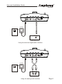
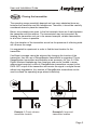
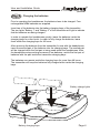
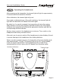
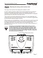
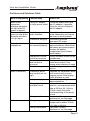
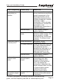
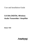
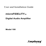
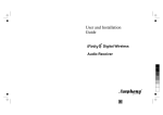
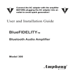
User and Installation
Guide
5.8 GHz DIGITAL
Wireless Headphones
Model 2500
R
R
User and Installation Guide
Unpacking: Check that this package contains:
One set of 5.8 GHz Digital Wireless Headphones, one 5.8 GHz Digital Audio
transmitter, one AC adapter, one dual RCA audio cable, four NiMh batteries.
Step 1
Connecting the transmitter
The transmitter provides 2 digital interfaces and 1 analog interface to connect
to an audio source.
Digital Audio Interface
The transmitter accepts a digital audio signal at both the electrical and optical
digital interface. By using one of the digital interfaces, audio data can be fed
directly into the transmitter. This bypasses the digital-to-analog and analog-todigital conversion and thereby eliminates audio distortion.
Many HiFi components provide a digital audio interface. The format of the
digital audio which is fed into the transmitter must be uncompressed S/PDIF
stereo data at a sampling rate of 32 kHz, 44.1 kHz or 48 kHz. Compressed
multichannel audio data (which is provided by many DVD players) cannot be
processed by the transmitter. In such case, set the format of the DVD player
audio interface to uncompressed stereo data.
Connect the digital audio output of the audio source with the digital audio
interface of the transmitter by using an RCA cable if the electrical interface is
used. If the optical interface is used, connect the transmitter by using an
optical audio cable (not included).
Analog Audio Interface
Analog audio can be fed into the transmitter via the analog audio interface.
Analog audio is converted to digital audio inside the transmitter by an analogto-digital converter.
The analog audio interface can be connected to a line out interface which is
provided by most audio sources. The analog audio interface can also be
connected to other analog outputs by using an appropriate adapter.
The transmitter will accept maximum audio levels between 0.2 Vrms and
10 Vrms. Prior to operating the transmitter, the analog audio interface should
be set to the correct audio level by adjusting the analog audio interface level
control (see page 7).
DC Power Input
Connect the DC power input with the supplied AC adapter. The use of a surge
protector is recommended to protect the transmitter from power surges and
audio dropouts.
Page 1
R
User and Installation Guide
DC 9V
DATA
OUT
L
R
ANALOG IN
DIGITAL IN
AC adapter
DC 9V
400 mA
DIGITAL
OUT
Power outlet
Digital Audio Source
Using the electrical digital audio interface
DC 9V
DATA
OUT
L
R
ANALOG IN
DIGITAL IN
AC adapter
DC 9V
400 mA
Power outlet
AUDIO
LINE OUT
L
R
Analog Audio Source
Using the analog audio interface
Page 2
R
User and Installation Guide
Step 2
Placing the transmitter
The operating range essentially depends on how many obstacles there are
between the transmitter and the headphones. Therefore, it should be carefully
considered where to place the transmitter.
Below, two examples are given. In the first example, there are 4 walls between
the transmitter and the receiver. The transmission may be interrupted. By
locating the transmitter such as in the second example, reliable transmission
to all of the 6 rooms is possible.
Also, the elevation of the transmitter as well as the presence of reflecting walls
will influence the range.
It is suggested to experiment in order to find the best location for the
transmitter.
If sufficient coverage cannot be achieved by changing the location of the
transmitter, then the use of RangeBooster transmitters is suggested. These
RangeBooster transmitters are available as an accessory for your 2.4 GHz
Digital Wireless Headphones from Amphony and can be located in areas
where signal reception is difficult. RangeBooster transmitters connect to the
DATA OUT output of the transmitter and receive the signal in a digital format
without any degradation. Any number of RangeBooster transmitters can be
used to extend the operating range almost indefinitely.
R
R
Example 1: Poorly chosen
transmitter location
Example 2: Improved
transmitter location
Page 3
R
User and Installation Guide
Step 3
Charging the batteries
Prior to operating the headphones, the batteries have to be charged. Four
rechargeable NiMh batteries are supplied.
Insert two of the batteries into the battery charging bays of the transmitter.
The two lights “Battery 1” and “Battery 2” of the transmitter will light to indicate
that the batteries are being charged.
In order to operate the headphones quickly, leave the batteries inside the
charging bays for a few hours. In order to fully charge the batteries, leave
them inside the charging bays for 48 hours.
After removing the batteries from the transmitter for use with the headphones,
insert the second pair of the batteries into the charging bays. The second pair
will be charged while the first pair is being used inside the headphones. After
the headphones stop working because of low batteries, switch the first pair of
batteries with the pair inside the transmitter charging bays.
The batteries can remain inside the charging bays for more than 48 hours.
The transmitter will keep the batteries fully charged while inside the charging
bays.
Battery charge lights
R
Battery charging bays
Page 4
R
User and Installation Guide
Step 4
Inserting the batteries into the headphones
After charging the batteries, insert them into the headphones.
There are two battery compartments, located on both sides, each housing one
battery. To access each battery compartment, push on the outer edge of the
battery lid. This will release the battery lid. Then lift the middle portion of the
battery lid to gain access to the battery compartment.
Insert the battery by pressing the minus pole of the battery against the spring at
the bottom of the battery compartment until the plus pole can slide into the battery
compartment. The battery should snap into place.
Ensure that the plus pole of the battery properly contacts the battery contact
inside the battery compartment to allow proper operation of the headphones. If
necessary, rotate the battery inside the battery compartment until proper contact
is established.
Finally, close the battery lid by pushing the middle section. It should snap into the
closed position.
To remove the batteries, open the battery lid as described above and pull the
battery out of the battery compartment by pushing the battery towards the bottom
until the plus pole is released and slides out.
ATTENTION!
Never leave any batteries inside the headphones for very long
periods of time to prevent any damage to the headphones from
leaking batteries.
Push
1
Lift
2
3
Page 5
R
User and Installation Guide
Step 5
Operating the headphones
After powering up the transmitter, the transmit light will light for approximately
5 seconds while the transmitter initializes.
After initialization, the transmit light will go out.
Once audio is detected at any of the audio interfaces, the transmit light will
light and the transmitter will transmit the audio signal.
By default (or if no audio is present), the transmitter will select the analog
audio interface. As soon as a signal is detected at either one of the digital
interfaces, the transmitter will activate the appropriate interface and light the
corresponding interface indicator.
Set the volume control of the headphones to minimum. Then, switch on the
headphones and slowly increase volume.
After each use, be sure to switch off the headphones to extend battery life and
to prevent damage to the headphones from leaking batteries.
When no audio is present anymore, the transmitter will go into standby mode
after approximately 1 minute. The transmit light will go out. During standby
mode, no signal is transmitted. If the headphones are not used for an
extended period of time, remove the AC adapter from the power outlet.
Interface indicators
Transmit light
R
Page 6
R
User and Installation Guide
Step 6
Adjusting the analog audio interface level
This step is only required if the analog audio interface is used.
In order to achieve maximum audio volume at the headphones and maximum
dynamics of the digital transmission and to avoid clipping of the audio, it is
necessary to set the analog audio interface level of the transmitter to correspond
with the maximum audio level of the audio source.
This is done by turning the analog audio interface level control knob which will
change the audio level inside the transmitter before it is converted to digital audio
by the transmitter analog-to-digital converter.
While listening over the headphones, turn the input audio level control knob to the
position that yields maximum loudness of the audio at the headphones without
any clipping (distortion). If the level is set too low, the dynamics of the
transmission are not fully used. If the level is set too high, clipping (distortion) of
the audio will occur.
ATTENTION!
Listening over headphones at high audio levels can cause
hearing impairments! Also, switching between different audio
sources, connecting and disconnecting the transmitter, and
the transmitter going into standby mode can cause loud clicks
and pops which can impair your hearing! Therefore, always set
the volume control to minimum.
Analog audio interface level control
R
Page 7
R
User and Installation Guide
Problems and Solutions Table
What is Happening Possible Why
What to Do
None of the
transmitter
interface indicators
will light after DC
power is applied
The transmit light
goes out after a few
seconds and does
not light again
Faulty AC adapter
Check the power outlet and
or faulty power outlet the AC adapter; if possible,
check for correct voltage of
the AC adapter
No audio at
headphones
Batteries empty or
not inserted properly
No audio present at
audio interface
Transmitter hung up
Headphone volume
control at minimum
Transmitter audio
level control at
minimum
Receiver hung up
Audio is distorted
Transmitter audio
level control set too
high
Batteries empty
Wrong digital
interface format
Strong interference
Audio is noisy
Wrong sample rate
Strong interference
Check the audio connection
to the transmitter and ensure
that there is audio present
Disconnect and then
reconnect DC power
Check battery voltage or
replace batteries, ensure that
the battery plus pole properly
touches the battery
compartment plus contact;
rotate battery
Slowly increase volume at the
headphones
Slowly rotate the transmitter
audio level control if the
analog audio interface is used
Switch headphone power off
and on
Regulate the transmitter audio
level control until no more
clipping occurs if the analog
audio interface is used
Check battery voltage or
replace batteries
Ensure that the transmitter
receives uncompressed audio
data at 32 kHz, 44.1 kHz or
48 kHz; check the audio
interface setting of the audio
source
See under „Strong
Interference“ on next page
Ensure that the audio data
sample rate is either 32 kHz,
44.1 kHz or 48 kHz
See under „Strong
Interference“ on next page
Page 8
R
User and Installation Guide
What is Happening Possible Why
What to Do
Audio drops out
intermittently or
crackles
In some cases, there may be
strong interference preventing
proper transmission of the
audio signal which can be
caused by microwave ovens,
cordless telephones, wireless
networks or video
transmitters. Either eliminate
the interference, relocate the
transmitter or use
RangeBooster transmitters to
improve reception.
Check battery voltage or
replace batteries
Ensure that the power outlet
delivers a stable voltage. Very
strong surges or voltage
fluctuations may cause audio
dropouts. Try using a surge
protector.
See under „Strong
Interference“ above
Audio will drop out if there are
too many obstacles between
the transmitter and the
headphones (see page 3), try
relocating the transmitter to
improve reception or use
RangeBooster transmitters
Check battery voltage or
replace batteries
Some audio devices stop
transmitting audio data
between different music
tracks for a short period of
time. This causes the
transmitter to deactivate the
digital interface while no audio
is received which causes
crackling of the audio
between music tracks.
Ensure that the digital
interface of the audio device
is activated
Strong interference
Batteries empty
Unstable power
supply
Transmitter range is Strong interference
extremely short
Too many obstacles
Batteries empty
Audio crackles
between music
tracks
Audio device
interrupts audio
stream
Transmitter does
not switch to digital
interface
No digital signal
present
For more information, including a detailed troubleshooting
guide, visit the Amphony web site at: www.amphony.com
Page 9
R
User and Installation Guide
Technical Specifications
Transmitter:
Audio transmission method: Digital
Transmitter frequency: 5.8 GHz
Signal-to-Noise ratio (A-weighted): typ. 100 dB 1)
Dynamic range: typ. 100 dB
1)
Channel separation: typ. 100 dB
1)
Harmonic distortion: typ. -90 dB
1)
Error correction: 1/2 rate FEC
Audio sampling method: 64 times oversampling
Transmitted data rate: > 3 Mbps
Data available at high-speed data port
Transmitter operating range (without RangeBooster modules):
max. 200 ft. line of sight, max. 50 ft. through walls and ceilings
Headphones:
Type: dynamic, closed
Operating time: max. 100 hours with two AA batteries
Frequency response: 20 Hz ... 24 kHz
Maximum sound pressure level: 120 dB
Note: 1) Performance is given for operation with a digital audio interface
Copyright (C) 2004 Amphony. All rights reserved.
The information contained herein is subject to change without notice.
Revisions may be issued to advise of such changes and/or additions.
All product names, trade names, or corporate names mentioned in this
document are acknowledged to be the proprietary property of the registered
owners.
This device complies with part 15 of the FCC Rules. Operation is subjected
to the following two conditions: 1) This device may not cause harmful
interference and 2) this device must accept any interference received,
including interference that may cause undesired operation.
Caution: Any changes or modifications not expressly approved by the party
responsible for compliance could void the user's authority to operate the
equipment.
Made in China.
Page 10
Limited warranty
WHAT YOUR WARRANTY COVERS
This warranty extends only to the original user of the equipment (“you”, ”your”) and is limited to the
purchase price of each part. Amphony and it’s affiliated companies (”we”, ”our”, ”us”) warrant this
Wireless Headphone Set against defects in materials or workmanship as follows.
LABOR: For a period of ninety (90) days from the original date of purchase, if we determine that the
equipment is defective subject to the limitations of this warranty, we will replace it at no charge for labor.
We warrant any such work done against defects in materials or workmanship for the remaining portion of
the original warranty period.
PARTS: For a period of one (1) year from the original date of purchase, we will supply, at no charge, new
or rebuilt replacement parts in exchange for parts we determine are defective subject to the limitations of
this warranty. We warrant any such replacement parts against defects in materials or workmanship for
the remaining portion of the original warranty period.
Note: ”Parts” means items included in this package. It does not include other parts purchased seperately.
WHAT YOUR WARRANTY DOES NOT COVER
This warranty does not cover consumer instruction, physical setup or adjustment of any consumer
electronic equipment, headphone batteries, or signal transmission problems.
This warranty does not cover cosmetic damage, damage due to the affixing of any attachment not
provided with the product, loss of parts, connecting the product to any but the specified receptacles,
lightning, electrical surges, fire, flood, or other acts of God, accident, misuse, abuse, repair or alteration
by other than authorized service personnel, negligence, commercial or institutional use, or improper or
neglected maintenance.
This warranty does not cover equipment sold AS IS or WITH ALL FAULTS, equipment removal or
reinstallation, shipping damage if the equipment was not packed and shipped in the manner we
prescribe, nor equipment purchased, serviced, or operated outside the contiguous United States of
America.
LEGAL LIMITATIONS
REPLACEMENT AS PROVIDED UNDER THIS WARRANTY IS YOUR EXCLUSIVE REMEDY. WE
SHALL NOT BE HELD LIABLE FOR ANY INCIDENTAL OR CONSEQUENTIAL DAMAGES FOR
BREACH OF ANY EXPRESSED OR IMPLIED WARRANTY ON THIS EQUIPMENT, NOR FOR ANY
INCIDENTAL OR CONSEQUENTIAL DAMAGES RESULTING FROM THE USE OF, OR INABILITY TO
USE, THIS EQUIPMENT. UNDER NO CIRCUMSTANCES SHALL OUR LIABILITY, IF ANY, EXCEED
THE PURCHASE PRICE PAID FOR THIS EQUIPMENT, EXCEPT TO THE EXTENT PROHIBITED BY
APPLICABLE LAW. EXCEPT AS PROVIDED HEREIN, WE MAKE NO WARRANTIES, EXPRESS OR
IMPLIED, INCLUDING WARRANTIES OF MERCHANTABILITY AND FITNESS FOR A PARTICULAR
PURPOSE. WE RESERVE THE RIGHT TO REFUSE TO HONOR THIS WARRANTY IF WE
DETERMINE ANY OF THE ABOVE EXCEPTIONS TO HAVE CAUSED THIS EQUIPMENT NOT TO
HAVE PERFORMED PROPERLY. THIS WARRANTY SHALL BE VOID IF ANY FACTORY-APPLIED
IDENTIFICATION MARK, INCLUDING BUT NOT LIMITED TO SERIAL NUMBERS AND WARRANTY
LABELS, HAS BEEN ALTERED OR REMOVED. THIS WARRANTY SHALL ALSO BE VOID IF THE
TRANSMITTER OR HEADPHONES HAVE BEEN OPENED BY AN UNAUTHORIZED PERSON (with
the exception of opening the battery lid on the outside of the headphones).
This warranty gives you specific legal rights which may vary from state to state. Some states do not allow
the exclusion or limitation of incidental or consequential damages, or allow limitations on the duration of
an implied warranty, so those limitations may not apply to you.
Note: No responsibility is assumed for the presence of interference outside of Amphony’s control, such
as other transmitters or microwave ovens, which may hamper proper signal reception.