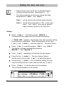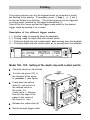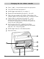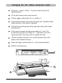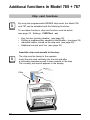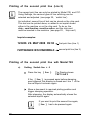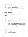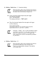
1
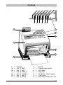
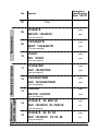
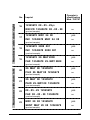
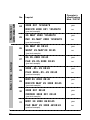
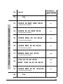
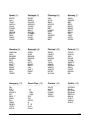
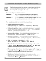
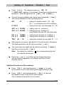
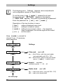
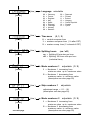
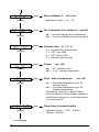
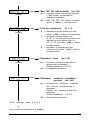
Operating Instructions
Multi - Printer
Models 780 / 785 / 787
Multi-purpose electronic stamp
with selectable printing functions
Version 4.5
© 2004 Ernst Reiner GmbH & Co. KG
All rights reserved. Translations, reprints, or any other form of
reproduction of this manual, in whole or in part, and in any form
whatsoever require our expressed permission in writing.
We reserve the right to alter the contents of this manual without notice.
This manual has been prepared with the greatest care, however,
we accept no responsibility for possible errors or omissions,
or for damage that may result from such errors or omissions.
2
Table of contents
Safety instructions ....................................................................................... 4
Control elements ......................................................................................... 5
Transport lock ............................................................................................. 6
Choosing a suitable location ........................................................................6
Mains connection and commissioning .........................................................6
Accumulator ................................................................................................ 7
Setting the date and time ............................................................................ 8
Printing ....................................................................................................... 9
Model 780 - 785: Setting of the depth stop with contact switch .........9
Model 787: Setting of the depth stop with contact switch ...................
10
Switching off the depth stop with contact switch .................................
10
Setting of the side stop .........................................................................
11
Impression positioning .........................................................................11
Activating upside down imprint ............................................................11
Setting the imprints .....................................................................................12
Stored imprints ............................................................................................13
Setting a pre-text .........................................................................................18
Functional description of the Numberer (num) ............................................
20
Setting of Numberer / Number / Text .........................................................21
Settings .......................................................................................................22
Changing the ink-ribbon cassette ................................................................
26
Changing the ink-ribbon protection mask ....................................................
27
Chip-card functions .....................................................................................28
Key function (printing disable) ..............................................................
29
Operator’s identification on the chip card ............................................
29
Printing of the first print line (Line 1) from chip card ...........................
29
Printing of the second print line (Line 2) ..............................................
30
Printing of the second print line with Model 785 ..................................
30
Printing of the second print line with Model 787 ..................................
31
RS 232 interface ..........................................................................................
33
Radio clock ................................................................................................ 34
User’s hints and error codes ..................................................................... 35
Reset ...........................................................................................................37
Technical data .............................................................................................38
Certifications ...............................................................................................39
Safety instructions
In this section, you will find safety instructions that you must always
observe when handling and working with your Electronic Stamp.
•
This machine complies with the relevant safety regulations
for information technology equipment, including office machinery
•
Transport the machine only in its original package or other suitable
package that provides protection against shock and impact
•
If the machine is taken from a cold environment into a warm room,
dew may form on it. Wait until the machine has warmed up to
room temperature and is absolutely dry before starting to use it.
•
Check that the local mains supply corresponds to the voltage,
given on the typeplate
•
This machine is intended for use with a safety-tested mains supply
and must only be connected to a mains socket with a protective earth
•
Make sure that the locally-installed mains socket with protective earth,
which you use to connect the machine, is readily accessible
•
The machine has no ON / OFF switch. To disconnect it from
the mains, you must pull out the plug.
•
Arrange the connection leads so that they do not create a hazard
(danger of tripping) and cannot be damaged.
Take care that no objects (e.g. necklaces, paper clips etc.) or liquids
fall into the machine (danger of electric shock or a short circuit)
•
•
In an emergency (e.g. in the event of damage to the machine casing,
control elements or the mains lead, or if an object or liquid falls
into the machine) disconnect the mains plug and notify your sales
agent or our service department
•
The machine contains components that carry a dangerous voltage
when the machine is in service. The machine must only be opened
by a qualified service-man. After maintenance or repair, the
effectiveness of electrical protective measures must be checked
to DIN VDE 0701. Unauthorised opening of the machine casing
and improper repairs can cause considerable danger to the user
(electric shock, fire hazard).
•
Avoid contact with freely-accessible PCB components, electrostatic
discharge could damage the machine or cause malfunctions
•
Freely-accessible PCB components do not carry mains voltage
4
Controls
1a 1b 1c 1d 1e 1f
8
1
2
3
7
4
5
6
1
1a
1b
1c
1d
1e
1f
=
=
=
=
=
=
=
Keypad
Key [ fkt ]
Key [ n/r ]
Key [ time ]
Key [ mode ]
Key [ set ]
Key [ line ]
2
3
4
5
6
7
8
=
=
=
=
=
=
=
Display
Trigger mode switch
Print head
Side stop
Feedplate (table trigger)
Front cover
Chip card for Model 785 / 787
5
Transport lock
Take out carton next to the print head on the left.
Attention! While taking out the carton don’t pull out the ink ribbon.
Take out carton on the left between upper part of machine and
document table
Choosing a suitable location
The choice of location for a REINER Multi-Printer is not particularly critical.
However, for safe, correct operation, please observe the following points:
•
Place the machine on a stable, smooth, and level surface in a room
with adequate ventilation (see also page 38, ‘Technical data’)
•
If the radio-clock function is to be used, make sure there is good
radio reception
•
Make sure that the mains socket which you use to connect
the machine is readily accessible
Mains connection and commissioning
Make sure that the device is connected to the correct mains voltage
as specified on the type plate on bottom of the device.
~ 230 V, 50 Hz
or
~ 115 V, 60 Hz
i
The device is also intended for IT - performance distributing net
with a phase voltage of ~ 230 V
Note
After plug in of the mains connector, the display indicates the following:
01 000000
num
rep
6
08 09: 38
27.05.
date
h
min
(see also page 17, imprint no. 38)
Accumulator
i
The accumulator saves data at power failure and is also sufficient
for a limited number of prints (see page 38, ‘Technical data’).
Note
Meaning of the accumulator symbol
+
in the display:
• Device is connected to mains:
+
is not displayed :
Accumulator is fully charged.
is flashing :
+
(by high frequents of printing)
With constantly frequenting of
printouts, it is possible to
trigger up to 100 prints.
Following the display
CHArGE bAT will appear.
Display CHArGE bAT :
Accumulator is charging,
device not yet ready for use.
The device is ready again in
approx. 15 minutes. The
accumulator is fully recharged
after approx. 20 hours.
• Device is not connected to mains:
+
is displayed :
Unit is in accumulator operation
+
is flashing :
Accumulator is close to be
discharged. About 100 prints
are possible, subsequent the
display EMPTY bAT will
appear.
Display shows EMPTY bAT
or no display:
Accumulator is discharged.
Stamping is not possible.
Connect the device to the
mains, after that the display
CHArGE bAT will appear.
7
Setting the date and time
i
•
Date and time can only be set if a selected imprint
contains at least the date (see pages 13 ... 17)
Note
•
The device disposes of dual input of time and date,
designated as date 1 and date 2
Date 1
will be used for the internal stored imprints
Date 2
will be used exclusively in 785. In this case,
date 1 and date 2 are used for special
stamp pictures, stored on the chip card
Setting:
Press [ time ] : The display shows MInUTE 1
The date and time appear and the minutes are flashing.
If PASS 0000 appears in the display, then date and time setting
is protected by a password. Enter the password via the keys
[ set ] and [ mode ] (see also page 25, ‘Password clock’)
Press [ line ] to switch between Date 1 and Date 2 .
The display changes corresponding between
MInUTE 1 and MInUTE 2
Press [ set ] repeatedly until desired minutes appear
Press the key [ mode ] : The hour display flashes.
Set the value of hours with [ set ] as described above
Press the key [ mode ] for successively calling the year,
month and day and set in each case with the key [ set ]
Press [ time ] to exit the date and time settings.
The set imprint appears on the display.
8
Printing
The printing process can only be triggered when no numerals or words
are flashing in the display. If necessary, press [ time ] or [ n/r ]
to stop the display from flashing. The printing process can be triggered
in various ways, selected by the trigger mode switch (3).
Take off the front cover and set the trigger mode switch to the desired
trigger mode by pushing it up or down.
Description of the different trigger modes:
1
2
3
4
=
=
=
=
Printing only by pressing down the feedplate
Printing only by depth stop with contact switch
Printing by depth stop with contact switch and pressing down the feedplate
Printing by depth stop with contact switch or by pressing down the feedplate
3
Model 780 - 785: Setting of the depth stop with contact switch
Place the device on its left side
Turn the red wheel (10) in
the direction of the arrow
to position 1 (see figure)
Press down the yellow
slide (9) and move it to
the desired value on
the scale (11).
(scale value = distance
from the top edge of the
paper to the centre of
the imprint in mm)
Release the yellow slide (9)
9
10
11
Set the desired trigger mode
9
Model 787: Setting of the depth stop with contact switch
Move the trigger mode switch (3) to position 2
15
17
Tip the machine on to its left side
Loosen the clamping screw (15)
Move the complete depth-stop
assembly (16) to the required
dimension on scale (17)
(scale value = distance from
upper margin to bottom edge
of impression in millimetres)
!
Caution
Be careful: Danger of
squeezing the fingers!
The depth-stop (16)
may be hot.
When adjusting, take care that the
depth-stop unit does not jam in its
guide. Touching the depth-stop unit
near its guide axis (18) helps to
prevent jamming.
16
18
Retighten the clamping screw (15)
Set the desired kind of triggering (see page 9)
Switching off the depth stop with contact switch
Push the yellow slide (figure on page 9) to scale value 95
Turn the red setting wheel (10) in the opposite direction
of the arrow (figure on page 9) to position 0
Turn the trigger mode switch (3) to the desired kind of triggering
i
Note
10
With Model 787, the depth stop cannot be switched off
Setting of the side stop
The red side stop for documents is located at the feedplate.
The adjustment can be carried out by moving the stop lateral.
Test of the imprint position
Carry out a test imprint
The rectangular cut-out (12) in the foil mask marks
the printing position. The imprint commences at the left
mark (13) on the foil mask
i
Note
Activating upside down imprint
Keep the key [ fkt ] pressed and at the same time press
the key [ set ]
An upside down symbol appears at the top right of the display.
The imprint commences at the right mark (14) on the foil mask.
To switch off upside down imprint, press the keys
[ fkt ] and [ set ] again.
The symbol disappears from the display.
i
Note
12
14
13
11
Setting the imprints
i
Note
Altogether there are 39 standard imprints stored in the
device. An overview of the stored imprints is shown
on the pages 13 ... 17. To select a desired imprint,
enter its corresponding number as follows:
Press the key [ mode ] for at least 5 seconds until
SETTinGS appears in the display
If PASS 0000 appears, the settings are protected by a password.
Enter the password via the keys [ set ] and [ mode ]
i
Note
Press [ line ]
the display shows ChiPCArd
Press [ mode ]
the display shows ST PiCTUrE
Press [ line ]
the number of the imprint is
displayed with one digit flashing
Entering the number:
Press [ set ] repeatedly, until
the desired tens digit number is shown
Press [ mode ]
the next digit is flashing
Press [ set ]
repeatedly until the desired digit is shown
Press [ n/r ]
repeatedly, until the imprint
appears in the display
By setting imprint 00 (possible only at Mod. 785 and 787)
the device prints exclusively data stored on a chip card.
(see also page 28, ‘Additional functions in Model 785 + 787’)
Examples of imprint no. 38 with explanations:
QUIT. 123456 29.05.08 09:40
pre-text
number
date
time
123456 29.05.08 09:40 BSP
number
12
date
time
operator’s identification
from chip card
Stored imprints
i
Note
The following imprints are shown below at their actual size.
An imprint which can be expanded with a pre-text is shown
under this with a pre-text example. The pre-texts and the
names of the months depend on the set language (see page 23).
No.
Imprint
00
Reserved for use of chip cards with customized
01
Operator’s
identification
Mod. 785/787
imprints and functions (Mod. 785 and 787)
yes
29. MAY 2008
yes
SENT 29. MAY 2008
yes
(pre-text sample)
02
29. 05. 2008
yes
RECVD 29. 05. 2008
yes
(pre-text sample)
Daters
03
2008 - 05 - 29
yes
INV. 2008 - 05 - 29
yes
(pre-text sample)
04
MAY 29 2008
yes
FAX MAY 29 2008
yes
(pre-text sample)
05
2008 001
yes
RECVD 2008 001
yes
(pre-text sample)
06
29. MAY 2008
yes
PAID 29. MAY 2008
yes
(pre-text sample)
13
No.
free
07
Numberers
08
Operator’s
identification
Mod. 785/787
Imprint
12345678
yes
RECVD 12345678
yes
(pre-text sample)
09
12345678
yes
SENT 12345678
yes
(Pre-text sample)
10
12345678
yes
INV. 12345678
yes
Numberers
with date right
Numerical stamps
(pre-text sample)
14
11
1234567890
yes
FAX 1234567890
yes
(pre-text sample)
12
1234567890
yes
FAX 1234567890
yes
(pre-text sample)
13
1234567890
yes
RECVD 1234567890
yes
(pre-text sample)
14
12345678 29. MAY 08
yes
FAX 12345678 29. FEB 08
no
(pre-text sample)
15
12345678 29. 05. 08
yes
FAX 12345678 29. 05. 08
no
(pre-text sample)
Numberer with date right
No.
16
Imprint
Operator’s
identification
Mod. 785/787
12345678 08 - 05 - 29ye
RECVD 12345678 08 - 05 - 29
no
(pre-text sample)
17
12345678 MAY 24 08
yes
INV. 12345678 MAY 24 08
no
(pre-text sample)
18
12345678 2008 001
yes
INV. 12345678 2008 001
no
(pre-text sample)
19
12345678 29. MAY 2008
yes
FAX 12345678 29. MAY 2008
no
Numberer with date left
(pre-text sample)
20
29. MAY 08 12345678
yes
FILE 29. MAY 08 12345678
no
(pre-text sample)
21
29. MAY 08 12345678
yes
PAID 29. MAY 08 12345678
no
(pre-text sample)
22
08 - 05 - 29 12345678
yes
FAX 08 - 05 - 29 12345678
no
(pre-text sample)
23
MAY 29 08 12345678
yes
SENT MAY 29 08 12345678
no
(pre-text sample)
15
Numberer
with date left
No.
24
Imprint
Operator’s
identification
Mod. 785/787
2008 001 12345678
yes
RECVD 2008 001 12345678
no
29. MAY 2008 12345678
yes
INV. 29. MAY 2008 12345678
no
(pre-text sample)
25
(pre-text sample)
26
29. MAY 08 08:45
yes
SENT 29. MAY 08 08:45
no
(pre-text sample)
Date / time stamp
27
29. 05. 2008 08:45
yes
FAX 29. 05. 2008 08:45
no
(pre-text sample)
28
2008 - 05 - 29 08:45
yes
FILE 2008 - 05 - 29 08:45
no
(pre-text sample)
29
MAY 29 2008 08:45
yes
RECVD MAY 29 2008 08:45
no
(pre-text sample)
30
2008 001 08:45
yes
ORDER 2008 001 08:45
yes
(pre-text sample)
31
MAY 29 2008 AM 08:45
yes
FAX MAY 29 2008 AM 08:45
no
(pre-text sample)
16
No.
32
33
Imprint
Operator’s
identification
Mod. 785/787
free
123456 29. MAY 2008 08:45
no
Time stamp with number and date
(Pre-text not possible)
34
123456 29. 05. 2008 08:45
no
123456 2008 - 05 - 29 08:45
no
(Pre-text not possible)
35
(Pre-text not possible)
36
123456 MAY 29 08 08:45
no
(Pre-text not possible)
37
38
39
40
000000 2008 001 08:45
yes
123456 29. 05. 08 08:45
yes
SENT 123456 29. 05. 08 08:45
no
123456 MAY 29 08 AM 08:45
no
(Pre-text not possible)
(Pre-text not possible)
free
17
Setting a pre - text
i
Note
Pre-text cannot be set with all imprints. This is only
possible if the imprint does not take the complete print line (see
table on pages 13 ... 17). The desired language must be set
before selecting the pre-text (see also page 23)
Press [ n/r ] :
If PASS 0000 appears in the display,
the setting of pre-text is protected
by a password. Enter the password
via the keys [ set ] and [ mode ]
Press [ line ]
repeatetly, until the display shows
P-TEXT
Select the desired pre-text with the key [ set ]
Note: Display _ _ _ _ _ means the setting without pre-text
The selected imprint appears
in the display
Press [ n/r ] :
The pre-text is shown on the display only when an imprint
without numberer is set
stored pre - texts:
18
Germany
(0)
__________
France
(1)
________
England
(2)
_________
Italy
(3)
______
EING.
AUSG.
BEARB
BEZ.
KASSE
QUIT.
REG.
BEST.
GEBU.
FAX
ERH.
ORIG.
RECU
PAYE
COPIE
AVOIR
URGT.
DUPLI
RAPPL
ANNUL
FCTE.
CONFD
ORIG
COMPT
RECVD
SENT
FILE
INV.
ORDER
ENT.D
DRAFT
PAID
RECPT
FAX
ORIG
REG.D
ARCH.
ARR.
PART.
NUMER
PAGAT
CASSA
PROT.
RACC.
REGIS
RICEV
SEGR.
VALUT
Spain
(4)
_______
Portugal
(5)
_________
Flemings
(6)
__________
Norway
(7)
________
ENTR.
SAL.
TRAT.
ARCHI
CAJA
PGDO.
VENT
RECIB
M.EXT
REG.
ANOT.
CONF.
ENTR.
SAÍDA
ELABO
ARQVO
CAIXA
PAGO
BALC.
RECIB
CAMBS
RGST.
LANÇ.
CONFI
ING.
UITG.
BEW.
AFLEG
KAS
BET.
LOKET
KWIT
DEV.
GEREG
GEB.
BEV.
INNG.
KASSE
BET.
REG.
BOKF.
BEKR.
MOTT.
BESV.
LEV.
FAKT.
OPPL.
OPRH.
Sweden
(8)
_________
Danmark
(9)
_________
Finland
(10)
__________
Poland
(11)
_________
ANKOM
AVS.
BEARB
KASSA
BET.
EXP.
KVITT
DNR.
BOKF.
BEKR.
LEV.
VERIF
INDG.
UDG.
BEARB
KASSE
BET.
KVIT.
BOGF.
BESV.
LEV.
FAKT.
EKSP.
FAX
SAAP.
LÄHET
KÄSIT
KASSA
KUIT.
TALL.
MAKS.
KOPIO
ARKIS
ALKUP
MITÄT
HYVAK
ORYG.
KOPIA
WPL.
PILNE
WYSL.
AKCEP
SPR.
.
WAZNE
ZAPL.
POUF.
DRUKI
NR
Hungary
(12)
___________
Czech
Rep. (13)
__________ _
Croatia
(14)
__________
Cyrillic
(15)
_________
RK.
FIZ.
ÁTUT.
KÖNYV
IKT.
BEV T
KIAD.
ELL.
ORIG.
REND.
COPY
SZLA.
¨
¨.J.
¨.Ú.
¨.OBJ
¨.ZAK
DAT.
ZN.
ORIG.
K.
P IJ.
VYD.
PLAC.
IZLAZ
ULAZ
PLA˘
PONIŠ
TERE˘
ISPOR
KOGBZ
BX.No
BCX.No
BA:HO
BEPHO
WEHA
CXET
3AKA3
AAKC
19
Functional description of the Numberer (num)
i
Note
The Numberer enables the ongoing numbering of imprints into
corresponding fields, indicated as num at the different,
stored imprints (see pages 13 ... 17)
The device disposes of dual numberer:
Numberer 1
6 or 8 characters (depending on set imprint)
will be used for the stored, device internal imprints
Numberer 2
(1 ... 8 characters ) is used exclusive in Mod. 785 + 787
for special imprints, stored on the chip card
The numbering field can include following settings:
•
20
Setting of the starting number
(Setting see page 21, AUT nr 1
respectively
AUT nr 2)
•
Setting of repetition (rep) enables the stamping of a constant
number with the set repetition factor (0 ... 99) . This is displayed
at the left (excepting the imprints 11 ... 13)
•
Incremental printing of an adjustable minimal value up to a
maximal value (setting see page 23, Mode n1 / n2 )
•
Decreasing printing of an adjustable maximal value to an
adjustable minimal value (setting see page 23, Mode n1 / n2 )
•
Skip of numberer (adjustable 0 ... 99 )
(setting see page 23 / 24, Skip n1 and
Skip n2)
•
Minimal value of numberer stored by pressing [ fkt ] and
[ set ] . Symbol
appears behind AUT nr 1 or AUT nr 2
Repeated pressing the keys shows the stored value
•
Maximal value of numberer stored by pressing [ fkt ] and
[ mode ] . Symbol
appears behind AUT nr 1 or AUT nr 2
Repeated pressing the key shows the stored value
•
Reset stored values of numberer (min. and max.)
Reset will be executed by pressing keys [ fkt ] and [ n/r ]
The symbols
and
disappear
Setting of Numberer / Number / Text
Press [ n/r ] : The display shows e g rEP 01 .
If PASS 0000 appears in the display, this setting is protected by a
password. Enter the password via [ set ] and [ mode ]
To scroll through available menu items, press repeatedly [ line ] .
The choose depends on the set stamp picture.
rEP
01
= setting of repetition factor (00 ... 99)
(00 = no increment count of numberer)
P- TEXT
= setting of pre-text (see also page 18 + 19)
AUT nr 1 000000
= setting value of numberer 1
AUT nr 2 000000
= setting value of numberer 2
(only Model 785 and 787 with chip card)
FIX nr 1
FIX nr 2
= setting fixed valuation of numberer 1
= setting fixed valuation of numberer 2
TExT
000000
000000
(01 ... 12)
= setting the contents of a text field 01 ... 12
After selection of a menu, right-hand of it the actual value is displayed.
The flashing position can be set by pressing [ set ]
The remaining input-digits can be called by pressing [ mode ]
and they can be set with [ set ]
Note:
By setting the character
be used as placeholder
the corresponding digit can
Press key [ n/r ] to quit the input and leave this menu.
The set imprint reappears in the display and Multi Printer
is ready to print
Additional functions of the numberer
Press [ fkt ] and simultaneously [ mode ] to reset
the numberer to zero with retaining the repetition factor (rep)
Press [ fkt ] and simultaneously [ fkt ] to interrupt
the repetition (rep) and print the next number.
The numberer increments to one number.
21
Settings
i
Note
The following menu ‘Settings’ features various adjustments
and configuration options of Multi Printer.
To call this menu, keep [ mode ] pressed for at least
five seconds until SETTInGS appears in the display.
If PASS 0000 appears, this menu is protected by a password.
Enter the password via [ set ] and [ mode ] .
Description
[ line ]
[ set ]
[ mode ]
[ n/r ]
of the key-functions in menu:
calling a displayed menu level
setting of numerical values
setting of non-numeric values. If a numerical
value is displayed, the various digits will be called
exit the menu
Keep [ mode ] pressed for
at least 5 sec. If necessary,
enter password
Settings
[ line ]
[ line ]
[ line ]
Imprint
selectable
available imprints = 00 ... 40
[ line ]
Radio clock
[ mode ]
see next page
22
(on / off)
on = Multi Printer with chip card reader
(only selectable with 785 + 787)
off = Multi Printer without chip card reader
(press [ mode ] to switch over)
[ mode ]
[ mode ]
Chip card
(on / off)
on = radio clock active (only with 785 + 787)
off = radio clock deactivated
[ line ]
00
01
02
03
04
05
06
07
08
[ mode ]
[ line ]
[ line ]
Germany
France
England
Italy
Spain
Portugal
Flemings
Norway
Sweden
Time zone
09
10
11
12
13
14
15
=
=
=
=
=
=
=
Danmark
Finland
Poland
Hungary
Czech Republic
Croatia
Cyrillic
(0, 1, 2)
Splitting hours
(on / off)
on = Splitting 60 minutes per hour
off = Splitting 100 time units per hour
(industrial time)
[ mode ]
[ line ]
Mode numberer 1
adjustable (1 / 2)
1 = Numberer 1 increasing from
minimum value up to maximum value
2 = Numberer 1 decreasing from
maximum value to minimum value
(description see also page 20)
[ mode ]
[ line ]
Skip numberer 1
adjustable
adjustment range = 01 ... 99
(description see also page 20)
[ mode ]
[ line ]
see next page
=
=
=
=
=
=
=
=
=
0 = central european time
1 = western european time (1 h after CET)
2 = eastern europ. time (1 h ahead of CET)
[ mode ]
[ mode ]
Language selectable
Mode numberer 2
adjustable (1 / 2)
1 = Numberer 2 increasing from
minimum value up to maximum value
2 = Numberer 2 decreasing from
maximum value to minimum value
(description see also page 20)
23
[ line ]
[ line ]
[ line ]
Summer time (0, 1, 2, 3)
0
1
2
3
[ mode ]
[ line ]
=
=
=
=
no switchover summer time
CET from 1996
CET before 1996
American summer time
Online
(on / off)
on = 24 - Interface active
off = V 24 - Interface deactivated
[ mode ]
[ line ]
Print - data transmission
(on / off)
on = Print-data transmission via V 24 Interface active
off = Print-data transmission via V 24 Interface deactivated
With setting ‘Record on’ data of stamp
picture (numberer, time and date, operator’s
identification and so on) can be transmitted
to a connected PC
[ mode ]
[ line ]
24
Pre characters 0 at numberer (on/off)
on = print and display of pre-characters 0
off = no print or display of pre-characters 0
[ mode ]
see next page
adjustable
adjustment range = 01 ... 99
(
[ mode ]
[ mode ]
Skip numberer 2
Delay time of contact switch
adjustment range = 000 ... 500 ms
(default = 100 ms)
[ line ]
Mod. 785 / 787 with controller
(on / off)
on = controller active (can only be selected
if Multi Printer is connected to
an external controller)
off = Mod. 780 / 785 / 787 without controller
(press [ mode ] to switch over)
[ mode ]
[ line ]
Print line switchover
0
[ mode ]
1
2
[ line ]
[ mode ]
(0, 1, 2)
= manually print line switch over with
button [ line ] without line adjustment
= automatic pint line switch over
at 787 to on with pint line switch over
manually pint line switch over at
787 to off by button [ line ] without
line adjustment
= automatic or manually pint line
switchover by button [ line ] without
line adjustment
Password clock
(on / off)
on = Access to setting time and date is
protected by a password
(Default-password = 2 4 6 8)
off = no password protection
[ line ]
Password
numberer / repetition /
pre-text
(on / off)
on = Access to set numberer, repetition
and pre-text is protected by a
password.
Setting ‘on’ requires to enter the
password.
(Default-password = 2 4 6 8)
off = No password protection
to exit ‘Settings’ press [ n / r ]
or
to go to the first menu press [ mode ]
25
Changing the ink - ribbon cassette
Press [ set ] , the print head moves to the right position
Turn up the front cover and remove it
Set the trigger mode switch (3) to position 2
Remove the used cassette by the grip (21). Do not tilt
Slide in the new cassette until it latches. While sliding in the
cassette, slightly turn the rotary button (22) in direction of arrow.
Position ribbon on right-hand roller guide (23) , push it
between the guides of the print head (25) and the red
foil mask (20) and position it on left-hand roller guide (24)
as you can see in figure below
Use the rotary button (22) to tighten the ink ribbon.
The ink ribbon must lie completely behind the white plastic
disks (23 u. 24) of the roller guides.
Set the trigger mode (3) to the desired position
Mount front cover
3
21
22
23
25
20
26
24
Changing the ink - ribbon protection mask
Press the [ set ] button: The print head moves to its
right-hand limit
Lift up the housing cover and remove it
Set the trigger mode switch (3) to position 2
First pull the left-hand end of the foil mask (20) forwards off the
frame (tension in the mask is released)
Pull the foil mask forwards off the right-hand side of the frame
and discard it
Fit the new foil mask with the arrow marks (13) and (14)
to the front (see figure on Page 12). First push it on to the
right-hand side of the frame until it reaches the stop.
Tension it slightly and push it on to the left-hand side of the
frame until it reaches the stop
Reset the trigger mode switch (3) to the required position
Refit the housing cover
3
14
13
27
Additional functions in Model 785 + 787
Chip card functions
i
Note
By using the programmable REINER chip cards, the Model 785
and 787 can be extended with the following functions:
To use these functions, chip card function must be active
(see page 22, Settings, CHIPCArd on)
•
•
•
•
Key function (printing disable) (see page 29)
Printing a supplementary operator’s identification (see page 29)
Individual imprint, stored on the chip card (see page 29)
Additional second print line (see page 30)
Insert the chip card smooth to the stop:
i
Note
The chip must be facing to the operator.
Insert the chip card vertically into the slot and after
a noticeable resistance push it down smooth to the stop.
The currently set imprint appears in the display.
Chip
28
Key function (printing disable)
i
Note
After activating the chip card function (see page 22, chip card on)
printing is only possible with an inserted chip card.
If the chip card is missing, InSErT CHIPCArd will be displayed.
Operator’s identification on the chip card
i
Note
An operator’s identification stored on the chip card can be
printed at the end of an imprint. This operator’s ID can be
combined with a standard imprint, stored in the device
or with a customer imprint, stored on the chip card.
First, the chip card function must be active (see page 22)
and the desired number of an imprint must be entered.
After inserting the chip card, the printing process can be
triggered.
The maximum printing width is 60 mm, so the operator’s
identification cannot be included with all imprints.
(see pages 13 ... 17)
Imprint example:
123456 29.05.08 09:40 BSP
operator’s identification
Printing of the first print line (Line 1) from chip card
i
Note
Before printing the Line1 stored on the chip card,
the chip card function must be active (see page 22) and
imprint no. 00 must be set (see page 13)
Insert the chip card. Subsequent the imprint
appears in the display and the device is ready to print
the first text line
29
Printing of the second print line (Line 2)
i
Note
The second print line can only be printed by Model 785 and 787.
Using Settings, the various types of line switching can be
selected and adjusted (see page 25, ‘switch line’)
An individual, second line of text can be stored on the chip card.
This text can be printed alone, or added to an imprint stored
either in the machine or on the chip card. To do so, the
chip - card function must be active and the chip card
must be inserted in the machine (see page 22, ‘chip card’)
Imprint examples:
123456 29. MAY 2008 09:38
first print line (line 1)
FURTWANGEN IM SCHWARZWALD
second print line (line 2)
Printing of the second print line with Model 785
a)
Setting Switch line = 0
Press the key [ line ] :
The Display shows:
TEXT LInE 2
If the [ line ] is pressed again before stamping
was triggered, this display is erased and line 1 of the
the set imprint is shown again
Move a document to required printing position and
trigger stamping operation.
After stamping, the display automatically shows the
selected imprint again.
i
Note
30
If you want to print the second line again,
[ line ] has to be pressed again
b) Setting Switch line = 1
i
Note
With this setting, Line 2 could printed as often as you
want until the [ line ] key is pressed again to return
to line 1 of the selected imprint
The printing process can be triggered as described
on page 30, a
c) Setting Switch line = 2
i
With this setting, after every stamping the machine
automatically switches to the next line
Note
Printing of the second print line with Model 787
i
Note
Model 787 contains a standard function for
‘semiautomatic two-line stamping’
A solenoid has been added to the depth stop to create
a stop unit. Using the standard setting (Setting ‘Switch
line = 0’) , the depth stop will be moved automatically
to a predefined line-spacing distance for stamping the
second print line (see also page 38, ‘Technical data’)
a) Setting Switch line = 0
i
Note
This setting provides the same function as described
on page 30, a
There is no line shifting
31
b) Setting Switch line = 1 (standard setting)
i
Note
With this setting, after every stamping the machine
automatically switches to the next print line, and at
the same time automatically changes line.
Push a document against depth stop and trigger
the stamping operation.
Line 1 will be printed.
The display switches to TEXT LinE 2
Move the document against the stop again and trigger
another stamping
Line 2 will be printed
The Display returns to the selected imprint and the
depth stop returns to print line 1 position.
i
Note
Using the [ line ] key, it is also possible to switch
manually to print line 2. In this case, the feed unit
does not change the position of the depth stop.
After stamping the machine automatically switches
to print line 1
c) Setting Switch line = 2
i
Note
32
With this setting, after every stamping the machine
automatically switches to the next print line.
There is no automatically change of the position
of the depth stop
RS 232 interface
i
Note
!
Caution
•
With Models 785 and 787, the RS 232 interface can be
used to connect the machine to a PC
•
The connection can be used as though it were to a printer.
Data can be sent from an application program to the
Multiprinter, which will print them.
•
An interface description to enable application programs to
be written is available from REINER
•
The interface connection is on the rear of the machine,
behind the round cover
To avoid damage to the machine and malfunctions due to
electrostatic discharge, keep the cover over the interface
socket whenever no cable is connected !
33
Radio clock
i
Note
The built-in radio clock receives automatically the central
european time. The precondition for this is the activation of
the radio clock (see page 22, ‘Radio clock’).
The time zone for eastern or western european time has to
be adjusted (see page 23, ‘Time zone’).
Reception of the radio time signals depends on the distance
of the device from the time signal transmitter Mainflingen
(Frankfurt / Germany) and on the device location (e.g. building).
The device automatically establishes radio communication
with the time signal transmitter at 3 a.m. The symbol
appears in the display when the device is receiving the time
signals. If the device receives no or only inadequate signals,
the attempt is discontinued after 12 minutes and thereafter
repeated hourly until a satisfactory signal has been received.
After activating the radio clock, its symbol is shown above the imprint
in the display with following status:
not flashing = reception ok, date / time set correctly.
slowly flashing = poor reception.
The attempt to receive will be discontinued after 40 seconds.
flashing once per second = receiving a good signal: After the
device has received the same time information (date + time)
three times in succession, the time is updated inside the device.
If the device receives different time information, it discontinues
the reception of the time signals after 12 minutes.
Manually triggering of the signal reception :
Press [ fkt ] and at the same time press [ time ]
The period of signal reception is prolonged if stamping operations are
carried out or settings are changed during the attempt to receive signals.
34
User’s hints and error codes
Display
Cause
Recommendation
CHArGE bAT
Accumulator is charging,
device is not ready for
operation
Connect device to mains.
Device is ready after
approx. 15 minutes
EMPTY bAT
Accumulator is
discharged
Connect device to mains.
Device is ready after approx.
15 minutes. Accumulator is
fully charged after 20 hours
InSErT
CHIPCArd
Chip card was not or
incorrectly inserted
Insert chip card correctly
(insert it smooth to
the stop)
InSErt CArd
FAstEr
Chip card was incorrectly
inserted or
Chip card was inserted but
not deep enough (not to
the stop)
Insert chip card correctly
(insert it smooth to
the stop)
Display is
dark
• Accumulator operation:
Accumulator is
discharged
Connect device to main.
It is ready after approx.
15 minutes, accumulator is
fully charged after 20 hours
• Mains operation:
Technical malfunction
Call technical service or
competent distributor
Error 02
Set number of imprint
is not available
Enter a valid imprint
(see page 13 ... 17)
Error 04
EEProm fault
Press [ set ] and
re-enter date and time
Error 08
Imprint exeeds maximum
width of 60 mm
Press [ set ] and
shorten the imprint,
e g deactivate pre text
35
Possible reason
Display
Error 10
Recommendation
• Print process not
executed completely
• Press [ set ] and
try to print again
• Ribbon cassette is
blocked
• Check ribbon cassette
and replace if necessary
Error 11
Numberer 1 :
Error 12
Numberer 2 :
Skip is larger or even 10
but numberer of imprint
is single-digit
delete error indication by
pressing [ set ] , following
set ‘Skip n1’ or ‘Skip n2’
to a value less than 10
(see page 23 / 24)
Error 15
•
•
Chip card inserted
incorrectly
Chip card is invalid
Insert a valid REINER
chip card correctly
Error 16
Not a REINER chip card
Use REINER chip card
Error 17
Key number of chip card
differs from key number
stored in the device
Correct key no. on chip card
or change the setting of
the device
Error 18
Data on chip card exceed
the maximum range of
imprint
Enter another imprint
to the chip card
Error 19
Number of imprint on chip
card doesn’t exist
Enter a valid number of imprint
to chip card
36
Reset
i
Note
•
With a Reset the device will be set to a defined status.
Furthermore the program run will be restarted (warm-start)
•
The pin used to operate the Reset should have a diameter
of about 2,5 mm and a rounded end
•
If a thinner pin with a sharp end is used (particularly a metal
pin, e.g. a straightened paper clip), there is a danger of
damage to the switch and PCB if it is not used very carefully
Carry out a Reset
Remove the front cover (7)
Press a thin pin-shaped object, about 4 cm long, vertically
into the small circular opening (see arrow) on the left below
the display (using for example a bent open paper clip)
until the display shows Test
Close the front cover (7)
The program is restarted. If the program is now being executed
correctly, time, date and data of numberer will be reset and
can now be set again
37
Technical data
Dimensions
Model 780 and 785 :
Model 787 :
175 x 160 x 163
175 x 160 x 171
(W x D x H in mm)
(W x D x H in mm)
Weight
Model 780 and 785 :
Model 787 :
ca. 3,2 Kg
ca. 3,6 Kg
Electrical data
Mains voltage :
Mains frequency :
Power consumption :
Stand-by time per
accumulator charge :
Accumulator charging time :
230 V ~
50 Hz
max.16 W
780, 785 : 7 days or 1000 impressions
787 : 7 days or 300 two-line impressions
ca. 20 hours
Impression data
Max. size of impression :
Paper thickness :
Carbon-copy performance :
Ink ribbon capacity :
Stamping time :
Stamping sequence :
Noise level :
60,44 mm x 3,2 mm (W x H)
multiple sheet with max. 2 mm thickness
3 to 4 carbon copies on NCR paper
min. 40 000 impressions (imprint no.
38 with pre-text)
ca. 0,5 seconds
> 2 seconds
max. 74 dB(A)
at print procedure
(workplace-related
emissions to ISO 7779)
Environmental conditions
Climate class :
generally to DIN IEC 68
Operation and storage :
temperature
relative humidity
0° C to + 40° C
10 % to 85 %
Transport:
temperature
relative humidity
- 30° C to + 60° C
10 % to 85 %
38
Certifications
Identification
This printer satifies the requirements of the EMV guideline
2004 / 108 / EG with regard to 'Elektromagnetic
compatibility’ in accordance with EN 55022 and
EN 55024.
As verification, the scanner bears the CE label.
Tested safety
REINER - Multi-Printers are manufactured and tested
in compliance with the safety standard EN 60950 - 1: 2001
WEEE Registration number
Disposal of electronic apparatus must not be in residual
waste or domestic waste.
39
Ernst REINER GmbH & Co. KG
Baumannstrasse 16
D - 78120 Furtwangen
Phone No.
Fax
Internet
E - Mail
+ 49 7723 6570
+ 49 7723 657 200
www.reiner.de
[email protected]
784 230 - 001 e
09 / 2008