
1
MeasureIT
Scanning Platform
SP 1200
Installation and Maintenance Manual
PROPRIETARY DATA
This document contains proprietary data of ABB Inc.
No disclosure, distribution (electronic or otherwise), reproduction,
or other means or dissemination may be made without written permission.
Produced by QCS Product Development.
Writers: Kay Brown, Bob Gongaware, Bill Houston, Robert Macchia, Pamela Murray
Artists: Melinda Hoyle, Kathleen Poirier
Contributors: Don Barger, Keith Carson, Jack Dukes, Mort Jensen, Al Luckman, Donald Stephens
© 1992 - 1993, 1996 - 2002 by ABB Inc. All rights reserved.
™ Smart Platform, 1190 Paper Machine Measurement and Control System, FirstSight Measurement Technology,
1180 MicroPlus, 1180 MICRO, OptiPak, and ACE are trademarks of ABB Inc.
™ DESQview is a trademark of QUARTERDECK OFFICE SYSTEMS.
® Teflon is a trademark of I.E. duPont de Nemours.
® AccuRay and ABB MasterAid are registered trademarks and service marks of ABB Inc.
March 2003
3BUS 208 000 R1301
(formerly 101764-003)
PROPRIETARY DATA: This document contains proprietary data of ABB Inc. No disclosure, distribution (electronic or otherwise),
or other means of dissemination may be made without written permission.
Document Version History
MeasureIT
Scanning Platform SP 1200
Installation and Maintenance Manual
Version
Level
Effective
Date
A
September
1992
B
January 1993
C
May 1993
63
D
September
1993
43
E
October 1993
F
Sections Changed
by Revision
Sections Added
by Revision
Original Release
Entire Manual
Replacement Parts for the
ASPC Section, page 213 and
page 217
November 1993 Entire Manual
G
May 1996
Entire Manual
H
September
1996
Setup Checklists, 104
Standardize Limits, 131-32
Default
Compensations for IR
Moisture,
Microwave, and Ash Sensors, 153
I
June 1997
Platfrom Software Setup
Checklist, Basic Tuning,
General Information, Control
Panel Description, Control
panel Functions, Replacement
Parts for the ASPC
Ash Sensor
J
July 1998
Entire Manual
K
November 1999 Power Down and DC Power
Analysis, Troubleshooting
Startup Messages
L
October 2001
M
May 2002
13
February 2003
3BUS 208 000 R1301
Entire Manual including
product name, cover art, and
header
Setup of Customer Units
Manual Part Numbers
Document Version History
Sections Deleted
by Revision
Blank Page
PROPRIETARY DATA: This document contains proprietary data of ABB Inc. No disclosure, distribution (electronic or otherwise),
or other means of dissemination may be made without written permission.
Preface
The audience for the MeasureIT Scanning Platform SP 1200 Installation and Maintenance
Manual,3BUS 208 000 R1301, is the person(s) who initially sets up and maintains the Scanning
Platform. The purpose of this manual is to provide for installation, setup, and maintenance of the
Scanning Platform.
While limited information is included, the user is expected to be somewhat familiar with operations
related to the Service Workstation and Health Reports. Additional background is available in the
documents listed below.
Note:
If you are using the DOS/DESQview version of the Service Workstation, you need
Version K of 101764-003.
The following documents are recommended for maintenance of the Scanning Platform:
•
Liquid Cooling Unit Reference Manual, 3BUS 208 146 RXX01
•
Scanning Platform System Software Manual, 3BUS 208 [049-054] RXX01
•
Scanning Platform Troubleshooting Procedures Manual, 3BUS 208 055 RXX01
•
Radiation Safety Manual (for customers), 3BUS 208 089 RXX01
•
Field Radiological Procedures Manual (For ABB personnel only 016263-001)
•
Specific sensor manuals
3BUS 208 000 R1301
Preface
i
Blank Page
PROPRIETARY DATA: This document contains proprietary data of ABB Inc. No disclosure, distribution (electronic or otherwise),
or other means of dissemination may be made without written permission.
Caution and Warning Symbols
General Safety Forms and Colors
Geometric Form and Meaning
Meaning
Geometric Form
Prohibition or
mandatory action
Warning
Information (including
instructions)
General Meaning of Safety Colors
Safety
color
Red
Meaning or Objective
Stop
Prohibition
Example of Use
Stop signs
Emergency stops
Prohibition signs
This color is also used for fire-prevention and fire-fighting
equipment and its location
Blue1
Mandatory action
Obligation to wear personal
protective equipment
Yellow
Caution, risk of danger
Indications of dangers,
(fire, explosion, radiation,
toxic hazards, etc.)
Warning for steps, low
passages, obstacles2
Green
Safe condition
Escape routes
Emergency Exits
Emergency showers
First-aid and rescue stations
1. Blue is considered a safety color only if used in a circular shape.
2. Fluorescent orange-red may be used in place of safety yellow except on safety
signs. This color is very conspicuous, especially in conditions of poor natural
lighting.
3BUS 208 000 R1301
Warning
iii
PROPRIETARY DATA: This document contains proprietary data of ABB Inc. No disclosure, distribution (electronic or otherwise),
or other means of dissemination may be made without written permission.
Definition of Cautions and Warning Symbols
The following symbols represent warnings and cautions which you may find on the
product or in product documentation.
This symbol warns of dangerous voltage. This symbol
is used if there is a danger of a harmful or fatal shock.
This is a radiation warning and is used when ionizing
rays are present. Where a lamp is used to indicate the
presence of ionizing radiation it is red.
This is a general warning symbol and is to be used if
there is no other more specific symbol available.
This symbol warns of potential electrostatic
sensitive devices. It is used as a reminder to
observe all electrostatic discharge control
procedures.
This symbol warns of a potential crushing hazard.
For example, if the motor controller is not properly
adjusted to stall, it may be possible for someone to be
crushed between the head package and the end
column.
This symbol warns of a potential hand or
finger entrapment hazard.
iv
Warning
3BUS 208 000 R1301
PROPRIETARY DATA: This document contains proprietary data of ABB Inc. No disclosure, distribution (electronic or otherwise),
or other means of dissemination may be made without written permission.
This symbol warns that equipment may
automatically start-up.
MOTOR ONLY
This symbol is a reminder that the motor must be
locked off before performing any action where
unexpected movement of the head package or any of
the associated drive elements would pose a hazard.
Note that the motor lock-out switch removes power
from only the motor controller and motor. It does
NOT remove all power from the SP.
This symbol is a reminder that it is mandatory to
read and understand the supporting manual before
proceeding. Additional necessary information is in
the manual.
WARNING
See WARNING text.
Exposed moving parts can
cause severe injury.
Do not operate machine
without guards in place.
Follow look out procedure
before servicing machine.
4.5 TONS
3BUS 208 000 R1301
Warning
This symbol indicates the maximum
weight of an SP and refers to this manual for
more information. See Chapter 3,
“Hardware Installation”.
v
Blank Page
PROPRIETARY DATA: This document contains proprietary data of ABB Inc. No disclosure, distribution (electronic or otherwise),
or other means of dissemination may be made without written permission.
Table of Contents
Preface ........................................................................................... i
Caution and Warning Symbols ................................................. iii
List of Figures ............................................................................ xv
1 Product Overview..................................................................... 1
SP 1200 Options ............................................................................................3
ABB Smart Processing Center (ASPC) Backplane Identification............. 4
Introduction ...........................................................................................................4
Identifying Different Backplanes ..........................................................................4
Slot Assignments ...................................................................................................5
Print Books ............................................................................................................6
± 12 Volt Fuses......................................................................................................6
Mechanical Structure .................................................................................... 7
Way System...........................................................................................................8
Drive System ................................................................................................. 9
Electrical and Cable Systems .................................................................... 10
Service Workstation.................................................................................... 12
Service Tools ............................................................................................... 13
2 Radiological Safety ................................................................ 15
Safety Features ........................................................................................... 16
Handling the Source ................................................................................... 18
Installation of the Source ........................................................................... 19
Individual Responsibility ............................................................................ 20
3 Hardware Installation............................................................. 23
Unpacking Instructions ..............................................................................24
Checklist ..............................................................................................................24
Handling Instructions ................................................................................. 25
Dimensions and Weight ......................................................................................27
Space Requirements ............................................................................................27
Safety ........................................................................................................... 28
Personnel .............................................................................................................28
Machine ...............................................................................................................29
Installation Requirements .......................................................................... 30
Environmental Data.............................................................................................30
Electrical Supply and Grounding Requirements .................................................30
Supply...........................................................................................................30
Grounding.....................................................................................................30
Scanning Platform Power Distribution Center (SPDC) ...............................31
Cabling ................................................................................................................31
3BUS 208 000 R1301
Table of Contents
vii
PROPRIETARY DATA: This document contains proprietary data of ABB Inc. No disclosure, distribution (electronic or otherwise),
or other means of dissemination may be made without written permission.
Equipment Location ............................................................................................32
ASPC Location.............................................................................................32
Scanning Platform Power Distribution Center (SPDC) ...............................32
Operator Control Panel Location .................................................................32
Blower Location ...........................................................................................32
Liquid Cooling Unit Setup .......................................................................... 33
Pedestal Installation and Alignment ......................................................... 34
Installation Guidelines.........................................................................................34
Alignment of the Customer Pedestals .................................................................35
Attaching the Platform to the Pedestals ................................................... 37
Platform Alignment .....................................................................................42
Carriage Alignment .....................................................................................44
Pass Angle Alignment ................................................................................ 45
Process Direction Alignment ..................................................................... 48
Air Gap Alignment....................................................................................... 50
Scan Direction Alignment .......................................................................... 52
4 Utility Service Installation ..................................................... 55
Air Purge ...................................................................................................... 56
Air and Water Supply .................................................................................. 57
Electrical Hook-Up ...................................................................................... 59
SP Power Up Procedure ............................................................................. 61
Starting Up the Software ............................................................................ 65
5 Platform Tuning...................................................................... 67
Platform Software Setup Checklist ...........................................................68
Motor Drive Setup (ABB ACS-100) ............................................................ 70
General Description.............................................................................................70
Control Panel Functions ......................................................................................70
Motor Drive Parameters ......................................................................................71
Motor Controller Setup (ABB Drive)..................................................................73
Motor Controller Adjustment of IR Comp (menu 306) ...............................73
Panel Operations..................................................................................................73
Moving Around the Menu............................................................................73
LOCAL/REMOTE .......................................................................................74
Setting a Parameter Value ............................................................................74
Downloading Parameters .............................................................................74
Uploading Parameters ..................................................................................75
Alarms and Fault Reporting ................................................................................76
Motor Controller Setup (Fincor and Lovejoy)........................................... 77
Basic Tuning................................................................................................ 81
viii
Table of Contents
3BUS 208 000 R1301
PROPRIETARY DATA: This document contains proprietary data of ABB Inc. No disclosure, distribution (electronic or otherwise),
or other means of dissemination may be made without written permission.
Head Position Setup ................................................................................... 88
Garage Position (OFF) .................................................................................88
Standardize Position (STDZ) .......................................................................88
Minimum Home Measure Position (LHEOS)..............................................88
Current Home Scan Position (KHEOS) .......................................................88
Default Single Point Position (SPPOS)........................................................88
Current Far Scan Position (KFEOS) ............................................................89
Maximum Far Measure Position (LFEOS) ..................................................89
Notes about LHEOS and LFEOS (Scanning Measurement Limits) ...................90
Procedure for LHEOS and LFEOS ..............................................................90
Procedure for Determining Position Values........................................................91
Head Package Dimensions Setup ............................................................. 92
Definition of Head Package Dimensions ............................................................92
Determining and Entering the Head Dimensions................................................95
Automatic Edge-of-Sheet ........................................................................... 97
Setup Guidelines..................................................................................................99
Entering AEOS Setup Parameters .......................................................................99
Motion Restriction Sensitivity.................................................................. 101
Changing the Motion Restriction Sensitivity.......................................... 102
Standardize Off-Sheet Delay Setup .........................................................103
Operation Overview ..........................................................................................104
Other Host Setup Procedures .................................................................. 105
6 Measurement Setup ............................................................. 107
Setup Checklists ....................................................................................... 108
Basis Weight Sensor Setup................................................................................108
IR Moisture Sensor Setup..................................................................................108
OptiPak Sensor Setup ........................................................................................109
Ash Sensor Setup...............................................................................................109
Gloss Sensor Setup ............................................................................................109
Apparent Density Setup.....................................................................................110
Caliper Sensor Setup .........................................................................................110
Sheet Temperature Sensor Setup.......................................................................110
Smoothness Sensor Setup..................................................................................111
Microwave Sensor Setup...................................................................................111
Smart Color Sensor Setup .................................................................................111
IR CoatWeight Sensor Setup.............................................................................111
Operation of NT Workstation Health Reports......................................... 112
Temperature Controller Setup for Basis Weight, Ash, and
Caliper Sensors .................................................................................. 115
Smart Ash and Smart Basis Weight ..................................................................116
Using the Optional Temperature Controller Utility ..........................................119
3BUS 208 000 R1301
Table of Contents
ix
PROPRIETARY DATA: This document contains proprietary data of ABB Inc. No disclosure, distribution (electronic or otherwise),
or other means of dissemination may be made without written permission.
Setup of Customer Units .......................................................................... 120
Ream Size..........................................................................................................120
Changing Ream Size ..................................................................................120
Apparent Density...............................................................................................120
Changing Caliper Output Units .........................................................................121
Ash Units Setup.................................................................................................121
Enter Calibration Head Constants ........................................................... 122
Basis Weight Sensor..........................................................................................122
Air Column Measurement (Smart Basis Weight Sensor Only).........................124
IR Moisture Sensor............................................................................................125
Ash Sensor.........................................................................................................127
Sheet Temperature Sensor .................................................................................128
Gloss Sensor ......................................................................................................128
Gloss Sensor Head Constant Tuning .................................................................130
Error Conditions.........................................................................................130
Caliper Sensor ...................................................................................................131
Microwave Moisture Sensor..............................................................................131
Standardize Limits .................................................................................... 132
General Information ..........................................................................................132
Time Interval between Standardizes ..........................................................132
The Selection of CLEAN or DIRTY Standardize Modes..........................132
Standardize Delay After Long Off-Sheet Periods......................................135
Reporting of "Internal" Check Sample During Standardize ......................135
Health Report Standardize Reports ............................................................136
Changing the Standardize Mode of the FCP Standardize Request ...................136
Controlling the Type of Standardize for a Specific Sensor ...............................137
Smart Basis Weight Sensors..............................................................................138
Caliper Sensor ...................................................................................................140
IR Moisture Sensor............................................................................................143
OptiPak Sensor ..................................................................................................144
Ash Sensor.........................................................................................................144
Gloss Sensor ......................................................................................................145
Verification................................................................................................. 146
Background........................................................................................................146
Phase I - Initial Static Verification ....................................................................146
Phase II - Process Measurement Verification ...................................................146
Phase III - Continuing Certification ..................................................................146
Implementation of the Sensor Verification Program.........................................147
Air Temperature Compensation for Basis Weight (TLK-5/-8/-9 ONLY) 148
Verification of Setup and Stability ....................................................................148
Fine Tuning ATC with dBWDT .......................................................................150
x
Table of Contents
3BUS 208 000 R1301
PROPRIETARY DATA: This document contains proprietary data of ABB Inc. No disclosure, distribution (electronic or otherwise),
or other means of dissemination may be made without written permission.
Air Profile Compensation for Ash, Basis Weight (TLK-5/-8/-9),
Caliper, Bottom & Top Gloss, and OptiPak ......................................152
Air Profile Collection ........................................................................................152
Enabling APC for Normal Measurement ..........................................................154
Digital Input Invert Adjustment for the Smoothness Sensor ................ 155
Default Compensations for IR Moisture, Microwave, & Ash Sensors.. 156
Calibrate Sample - Minimum Time Data Accumulation ......................... 157
7 Control Panel Operation...................................................... 159
Control Panel Description ........................................................................ 160
Scanning Platform Modes of Operation..................................................161
Remote/On-Sheet ..............................................................................................161
Remote/Off-Sheet..............................................................................................161
Local ..................................................................................................................161
Local/Head Split................................................................................................162
Control Panel Functions........................................................................... 163
Head Split Switches .................................................................................. 167
8 Startup Options .................................................................... 169
Manual Startup ..........................................................................................170
Automatic Startup ..................................................................................... 171
Service Workstation Software Startup.................................................... 172
9 Maintenance Procedures..................................................... 173
Scanning Platform Maintenance Log ...................................................... 174
Inspecting the Incoming Power ............................................................... 176
Inspecting the Drive System .................................................................... 177
Drive Belt Tension Measurement......................................................................178
Drive Belt Tension and Tip Adjustment ...........................................................178
Drive Motor Belt Inspection..............................................................................180
Drive Motor Adjustment ...................................................................................180
Seal Belt Tension Inspection .............................................................................181
Seal Belt Tension Adjustment ...........................................................................181
Head Separation and Limit Switch Inspection ..................................................182
Wheel Inspection....................................................................................... 184
Platform Alignment Inspection ................................................................185
Air Purge Filter Inspection .......................................................................186
Purge Blower Replacement Process..................................................................186
Cleaning the Air Purge Filter ............................................................................187
Inspecting the Compressed Air Filters ................................................... 188
Inspecting the Water Filter .......................................................................189
Power and Temperature Checks ............................................................. 190
DC Voltage Level Checks .................................................................................190
Cabinet Environmental Checks .........................................................................190
3BUS 208 000 R1301
Table of Contents
xi
PROPRIETARY DATA: This document contains proprietary data of ABB Inc. No disclosure, distribution (electronic or otherwise),
or other means of dissemination may be made without written permission.
10 Replacement Procedures .................................................... 191
Drive Motor Belt ........................................................................................192
Carriage Drive Belt .................................................................................... 194
Idler Pulley ................................................................................................. 196
Carriage Wheel ..........................................................................................197
Seal Belt ..................................................................................................... 198
Roller Assembly ........................................................................................201
Flex Cable Suspension ............................................................................. 202
Electric Chassis ........................................................................................205
Electric Chassis Replacement Procedure ..........................................................205
Flex Power Cable Retrofit Kit...........................................................................207
Flex Cable Replacements ..................................................................................207
Motor Drive Replacement (ABB ACS-100) .............................................. 209
Pressure Switch ........................................................................................210
Encoder ......................................................................................................211
Replacement Parts List ............................................................................212
Replacement Parts for the ASPC............................................................. 216
11 Troubleshooting................................................................... 223
Alarm Messages ........................................................................................224
Electronics Alarm Messages .............................................................................224
End Column Power Temp Out of Limits ...................................................224
Chiller Flow Out of Limits.........................................................................224
Voltage Level Out of Limits ......................................................................225
Communications Loss For Frame ECF/xxxx ECS ....................................225
Undefined Alarm........................................................................................225
Frame Alarm Messages .....................................................................................225
Motor Stopped by Obstacle........................................................................225
Head Position Verify Test - Timeout .........................................................225
Head Position Verify Outside Limits .........................................................225
Head Resynchronize - Timeout..................................................................226
Head Speed Inconsistency..........................................................................226
Beam Air Flow Off ....................................................................................226
Power Shelf Temperature Out of Limits ....................................................226
Motor Controller Temp Out of Limits .......................................................226
AI Slope and Offset Calc Failed ................................................................226
Undefined Alarm........................................................................................226
LED Interpretation..................................................................................... 227
Power Supply LEDs ..........................................................................................227
ECF and ECS LEDs ..........................................................................................228
MPRC LEDs......................................................................................................229
Power Down and DC Power Analysis ..................................................... 231
xii
Table of Contents
3BUS 208 000 R1301
PROPRIETARY DATA: This document contains proprietary data of ABB Inc. No disclosure, distribution (electronic or otherwise),
or other means of dissemination may be made without written permission.
Diagnostic Card Operation.......................................................................234
Diagnostics Performed at the Sensor.................................................................235
Diagnostic Cards ...............................................................................................237
Appendix A: Service Workstation Activities ......................... 245
Service Workstation Setup.......................................................................246
Software.............................................................................................................246
Hardware ...........................................................................................................246
Displaying Reports ...................................................................................247
Standardize Report ............................................................................................247
Sample Check Report ........................................................................................248
Calibrate Sample Report....................................................................................249
Utilities ....................................................................................................... 250
The inspect Utility .............................................................................................250
The gstore Utility...............................................................................................251
Identifying Sensor Configuration ............................................................ 253
Determining Software Release Levels .................................................... 254
Preparing On–Site Documentation.......................................................... 255
Index ......................................................................................... 257
3BUS 208 000 R1301
Table of Contents
xiii
Blank Page
PROPRIETARY DATA: This document contains proprietary data of ABB Inc. No disclosure, distribution (electronic or otherwise),
or other means of dissemination may be made without written permission.
List of Figures
Figure..................................................................................................Page
Figure 1-1
Figure 1-2
Figure 1-3
Figure 1-4
Figure 1-5
Figure 2-1
Figure 2-2
Figure 2-3
Figure 2-4
Figure 2-5
Figure 3-1
Figure 3-2
Figure 3-3
Figure 3-4
Figure 3-5
Figure 3-6
Figure 3-7
Figure 3-8
Figure 3-9
Figure 3-10
Figure 3-11
Figure 3-12
Figure 3-13
Figure 3-14
Figure 3-15
Figure 3-16
Figure 3-17
Figure 3-18
Figure 4-1
Figure 4-2
Figure 4-3
Figure 4-4
Figure 5-1
3BUS 208 000 R1301
System Overview ......................................................................
Platform Cross Section .............................................................
Carriage System ........................................................................
Drive System ............................................................................
Electrical Component Locations ...............................................
Shutter Status Lights on Lower Carriage and End Column .....
Types of Safety Labels Used on Shipping Containers .............
Safety Labels ............................................................................
Safety Label for the X–ray Sensor ............................................
Measurement Beam ..................................................................
Scanning Platform on Shipping Dollies ...................................
Rigging Recommendations .......................................................
Liquid Cooling Unit Setup ........................................................
Alignment of the Mounting Pedestals ......................................
Attaching Drive Side of Scanning Platform to Pedestals .........
Platform to Pedestal Installation – Idler Side ..........................
Preliminary Alignment Setup ...................................................
Jackscrew Orientation ...............................................................
Verifying Platform Alignment ..................................................
Head Alignment Conditions .....................................................
Pass Angle Adjustment .............................................................
Simulating the Process Pass Line .............................................
Pass Angle Adjustment Tool ....................................................
Process Direction Alignment Points .........................................
Air Gap Alignment Points ........................................................
Scan Direction Optimum Alignment Point ..............................
Scan Direction Adjustment .......................................................
Manual Alignment Setup ..........................................................
Purge Air Duct Attachment ......................................................
Air and Water Hookup ..............................................................
Standard Cable Configuration ..................................................
Circuit Breakers ........................................................................
Menu Tree .................................................................................
List of Figures
2
7
8
9
10
17
18
20
21
22
24
26
33
35
37
38
39
40
42
44
45
46
47
48
51
52
53
54
56
58
60
61
69
xv
PROPRIETARY DATA: This document contains proprietary data of ABB Inc. No disclosure, distribution (electronic or otherwise),
or other means of dissemination may be made without written permission.
Figure 5-2
Figure 5-3
Figure 5-4
Figure 5-5
Figure 5-6
Figure 5-7
Figure 5-8
Figure 5-9
Figure 5-10
Figure 5-11
Figure 5-12
Figure 5-13
Figure 5-14
Figure 5-15
Figure 5-16
Figure 5-17
Figure 5-18
Figure 6-1
Figure 6-2
Figure 6-3
Figure 6-4
Figure 6-5
Figure 6-6
Figure 6-7
Figure 6-8
Figure 6-9
Figure 6-10
Figure 6-11
Figure 6-12
Figure 6-13
Figure 6-14
Figure 6-15
Figure 7-1
Figure 7-2
Figure 9-1
Figure 9-2
Figure 9-3
Figure 9-4
Figure 9-5
Figure 9-6
xvi
MDPanel ...................................................................................
Manual Servo Calibration Screen in ft. ....................................
Location of the Motor Controller in the SP End Column .........
Adjustments to the Motor Controller ........................................
Head Position Calibration – Initial Display (Example) ............
Head Position Calibration Measurement ..................................
Head Position Calibration Screen .............................................
Head Position Calibration Summary Display ...........................
Motor Controller Servo Calibration Summary .........................
Automatic Motor Controller Tuning Screen ............................
Scanning Platform Positions at the Host Computer .................
Limits for Multiple Platform Installations ................................
NT Workstation Frame Health Report - Scanner Setup ...........
Location of Head Package Measurements ................................
Automatic Edge-of-Sheet Position Measurements ...................
NT Workstation Frame Health Report - AEOS Setup .............
NT Workstation Frame Health Report - Servo/Temp Setup ....
Menu Page with Links to Machines and Frames ......................
NT Workstation Frame Health Report - Overview ..................
NT Workstation Basis Weight Health Report - Heater ............
NT Workstation Caliper Health Report ....................................
NT Workstation Basis Weight Health Report - Calibration .....
NT Workstation Air Column Health Report - Setup ................
NT Workstation IR Moisture Health Report - Calibration .......
NT Workstation Ash Health Report - Calibration ....................
NT Workstation Temperature Health Report - Calibration ......
Gloss Sensor Calibration Report ..............................................
NT Workstation Caliper Health Report - Calibration ..............
Standardize Mode Selection .....................................................
NT Workstation BW Health Report - Standardize Limits .......
NT Workstation Caliper Health Report - Standardize Limits ..
Heat Source for Fine Tuning dBWdT ......................................
Scanning Platform Control Panel .............................................
Locations of the Head Split Switches .......................................
Scanning Platform Lockout Switch Location ...........................
Drive Belt Measurement and Adjustment ................................
Drive Motor Belt Check and Adjustment .................................
Seal Belt Tension Checks .........................................................
Seal Belt Adjustment ................................................................
Head Separation Switches ........................................................
List of Figures
70
78
79
80
82
83
83
85
86
87
89
90
91
94
98
100
102
112
114
116
121
123
124
125
127
128
129
131
134
138
140
150
160
167
177
179
180
181
181
183
3BUS 208 000 R1301
PROPRIETARY DATA: This document contains proprietary data of ABB Inc. No disclosure, distribution (electronic or otherwise),
or other means of dissemination may be made without written permission.
Figure 9-7 NT Workstation Sensor Health Report Voltage/Temperature History ..............................................
Figure 10-1 Drive Motor Belt ......................................................................
Figure 10-2 Air Clutch Drive Assembly ......................................................
Figure 10-3 Carriage Drive Belt ...................................................................
Figure 10-4 Idler Pulley ...............................................................................
Figure 10-5 Carriage Wheel .........................................................................
Figure 10-6 Seal Belt Clamp and Adjustment Bolts ....................................
Figure 10-7 Seal Belt ....................................................................................
Figure 10-8 Seal Belt Tension Checks .........................................................
Figure 10-9 Roller Assembly .......................................................................
Figure 10-10 Carriage Assembly (Top View) ..............................................
Figure 10-11 Cable Suspension ....................................................................
Figure 10-12 Carriage Assembly .................................................................
Figure 10-13 Side View of Proper Cable Dress for SP1200 ........................
Figure 10-14 SP Motor Drive Assembly ......................................................
Figure 10-15 Pressure Switch .......................................................................
Figure 10-16 Drive End Column Parts .........................................................
Figure 10-17 SP Electronics Cabinet (086345-004 Backplane Version) .....
Figure 10-18 SP Electronics Cabinet (086345-003 Backplane Version) .....
Figure 10-19 Location of SMI and BRAM Boards ......................................
Figure 10-20 Location of OSPS2 and EC24V .............................................
Figure 11-1 Subsystem Temperature Report ................................................
Figure 11-2 Historical Trend Report for Microcontroller DC Voltages ......
Figure 11-3 Test Board Hookup ...................................................................
Figure 11-4 Basis Weight Source Module ...................................................
Figure 11-5 Basis Weight Detector Module .................................................
Figure 11-6 Sample Diagnostic Card: Top Power ......................................
Figure 11-7 Sample Diagnostic Card: Bottom Power .................................
Figure 11-8 Sample Diagnostic Card: Top Signal ......................................
Figure 11-9 Sample Diagnostic Card: Bottom Signal Sensor .....................
Figure 11-10 Sample Diagnostic Card: Backplane Power ..........................
Figure 11-11 Sample Diagnostics Card: Bottom Auxiliary Power .............
Figure 11-12 Sample Diagnostics Card: Detector Module ..........................
Figure 11-13 Sample Diagnostics Card: Source Module ............................
Figure A-1 Debug Port on the Scanning Platform (-003 Backplane shown)
Figure A-2 Example of Standardize Report ................................................
Figure A-3 Example of Sample Check Report ............................................
Figure A-4 Example of Calibrate Sample Report .......................................
Figure A-5 gstore Menu Screen ..................................................................
3BUS 208 000 R1301
List of Figures
190
192
193
195
196
197
198
199
200
201
202
203
206
208
209
210
215
218
219
220
221
232
233
234
235
236
237
238
239
240
241
242
243
244
246
247
248
249
251
xvii
Blank Page
PROPRIETARY DATA: This document contains proprietary data of ABB Inc. No disclosure, distribution (electronic or otherwise),
or other means of dissemination may be made without written permission.
1
Product Overview
The SP 1200 is a full size (maximum of 12 meters long), high-performance
platform for medium-to-giant size paper machines with up to 10.2 meters (402
inches) of trim. The platform can carry up to seven sensors at a ± 25° pass angle
(optionally at a ± 45° pass angle). It has on-board electronics for local sensor and
platform signal processing. This chapter discusses the Scanning Platform hardware.
Figure 1-1 shows a typical SP 1200 based measurement system.
This chapter contains the following major sections:
Section ...............................................................................................Page
SP 1200 Options ............................................................................................
ABB Smart Processing Center (ASPC) Backplane Identification .................
Mechanical Structure .....................................................................................
Drive System ..................................................................................................
Electrical and Cable Systems .........................................................................
Service Workstation .......................................................................................
Service Tools ..................................................................................................
3BUS 208 000 R1301
Product Overview
3
4
7
9
10
12
13
1
PROPRIETARY DATA: This document contains proprietary data of ABB Inc. No disclosure, distribution (electronic or otherwise),
or other means of dissemination may be made without written permission.
Scanning Platform
Purge Blower
Water
Process
Compressed
Air
Liquid
Cooling Unit
Sensor(s)
Power
Transformer
(240 4-wire)
Service
Workstation
Host Computer System
Figure 1-1 System Overview
2
Product Overview
3BUS 208 000 R1301
PROPRIETARY DATA: This document contains proprietary data of ABB Inc. No disclosure, distribution (electronic or otherwise),
or other means of dissemination may be made without written permission.
SP 1200 Options
The SP 1200 can be configured with the following options listed below.
Sensor Options
The following sensors can be mounted on the SP 1200.
•
Basis Weight
•
Infrared Moisture
•
Caliper
•
Ash
•
OptiPak TM
•
Gloss
•
Temperature
•
Microwave Moisture
•
Edge-of-Sheet
•
Smoothness
•
Color
•
Smart ReflectionPlus CoatWeight
Scanner Options
The following options are also available for the SP 1200.
3BUS 208 000 R1301
•
High temperature scanner insulation kit
•
Remote electronics
•
Remote control panel
•
Extended end columns/extended pass angle
Product Overview
3
PROPRIETARY DATA: This document contains proprietary data of ABB Inc. No disclosure, distribution (electronic or otherwise),
or other means of dissemination may be made without written permission.
ABB Smart Processing Center (ASPC)
Backplane Identification
Introduction
With the introduction of the Smart Color sensor and the ReflectionPlus CoatWeight
sensor, it became necessary to introduce a new ASPC backplane, Part Number
086345-004. Previous updates to the ASPC backplane were all backward
compatible so there is little distinction between Part Numbers 086345-001,
086345-002, or 086345-003. The latest backplane, however, is not backward
compatible. It is important to be able to tell which backplane your scanner has.
Associated with the new backplane are new functional drawings, sensor cables, and
jumper plugs. External wiring for things like sheet break and chiller flow switches
are also different. Make sure you are using the correct documentation associated
with the particular version of backplane in your Scanning Platform.
Identifying Different Backplanes
The most positive identification of which backplane your system uses is to locate
and read the part number tag on the PWA. The location of this tag on the 086345004 backplane is above the programming plug, P1. Unfortunately, on some of the
older backplanes it is on the bottom; sometimes concealed by the heat exchanger
and plumbing.
The most obvious differences in the appearances of 086345-004 backplanes with
respect to earlier versions are changes in the types of connectors (see examples of
Backplanes 086345-004 and -003 in Figure 10-17 on page 218 and Figure 10-18
on page 219).
4
•
J8, J9, and J10 are 14-position connectors. On the earlier backplanes, the
connections for sheet break, reel turn-up, chiller flow switches, etc. (J8, J9, J10,
J11, and J12) were all 10-position connectors.
•
J11 is a new nine-position connector for wiring IR Sola transformers (replacing
J20 and J21); and there is not J12, J20, or J21.
•
The signal programming plugs P3, P4, and P5 were changed to 64 position from
position plugs.
•
The “AC IN” plug (J25) was changed to a nine-position plug from a fourposition plug.
Product Overview
3BUS 208 000 R1301
PROPRIETARY DATA: This document contains proprietary data of ABB Inc. No disclosure, distribution (electronic or otherwise),
or other means of dissemination may be made without written permission.
Slot Assignments
These are the typical slot assignments for Part Number 086345-004 backplane:
Slot
I.D.
Function
0
ECPSR
ECPSR
1
MPRC
MPRC
2
0x1F
ECF
3
0x21
Basis Weight
4
0x02
HemiPlus IR
5
0x03
Caliper
6
0x04
OptiPak OR Top Reflection IR
7
0x25
Dual Gloss OR Top Reflection IR
8
0x26
Ash OR Bottom Reflection IR
9
0x27
BW HAW & Microwave & Temperature & Smoothness OR
Specials
These are the typical slot assignments for Backplane Part Numbers 086345-001,
086345-002, and 086345-003:
3BUS 208 000 R1301
Slot
I.D.
Function
0
ECPSR
ECPSR
1
MPRC
MPRC
2
0x1F
ECF
3
0x01
Basis Weight
4
0x22
HemiPlus OR Top Reflection IR OR
Bottom Reflection IR
5
0x23
Caliper
6
0x24
OptiPak
7
0x05
Dual Gloss
8
0x06
Ash
9
0x27
Color & Microwave & Temperature OR BW HAW &
Microwave & Temperature & Smoothness OR Specials
Product Overview
5
PROPRIETARY DATA: This document contains proprietary data of ABB Inc. No disclosure, distribution (electronic or otherwise),
or other means of dissemination may be made without written permission.
Print Books
Because of the wiring and program jumper changes, there are two separate Scanning
Platform print books. The print books associated with the different backplanes are:
Backplane
Print Book
086345-004
3BUS 208 006 RXX01
086345-003
3BUS 208 003 RXX01
086345-002
3BUS 208 003 RXX01
086345-001
3BUS 208 003 RXX01
± 12 Volt Fuses
There are some very specific requirements in the National Electric Code (NEC)
Article 725 having to do with cable types for power-limited circuits. To increase
the selection of allowable cable types, fuses were added to the +12 Volt and -12 Volt
circuits on Backplane Part Number 086345-004 for sheet break, reel turn-up, chiller
flow switches, etc. They are 5 amp fuses located between J8 and J9.
6
Product Overview
3BUS 208 000 R1301
PROPRIETARY DATA: This document contains proprietary data of ABB Inc. No disclosure, distribution (electronic or otherwise),
or other means of dissemination may be made without written permission.
Mechanical Structure
The platform beams are constructed of custom pressed, steel box beams. The cross
section is shown in Figure 1-2.
Torsion
Box
Payload
Area
Figure 1-2 Platform Cross Section
The end columns are also made of steel box sections. The Scanning Platform is
welded together in a rigid ‘‘O”. The end columns house on-platform electronics
and a drive system.
For longitudinal expansion, there is a Teflon® glide pad mounted under one end
column. The other end column is fixed.
3BUS 208 000 R1301
Product Overview
7
PROPRIETARY DATA: This document contains proprietary data of ABB Inc. No disclosure, distribution (electronic or otherwise),
or other means of dissemination may be made without written permission.
Way System
The upper and lower sensors are carried across the web by means of a two-way
system with four wheels on each carriage. The principle of operation is shown in
Figure 1-3.
NOTE: The encoder and drive shaft have been removed for clarity.
Figure 1-3 Carriage System
The weight of the carriage is carried on the side way bars which provide precision
of motion. The horizontal guidance is provided by contoured wheels.
The carriage wheels are made from a hard, carbon fiber and Teflon reinforced
polymer. The bearings are permanently lubricated ball bearings.
The way bars are permanently laser aligned at the factory and locked by high strength
fasteners. The side way mounting bolts are covered by self-locking plastic push
buttons.
Note: The way bar alignment is never to be adjusted in the field.
8
Product Overview
3BUS 208 000 R1301
PROPRIETARY DATA: This document contains proprietary data of ABB Inc. No disclosure, distribution (electronic or otherwise),
or other means of dissemination may be made without written permission.
Drive System
The upper and lower carriages are traversed across the web by the drive system.
The principle of operation is shown in Figure 1-4.
Idler
End
Encoder
Upper Drive Belt
Drive
Pulley
Idler
Pulley
Drive
Shaft
Motor
Controller
Bearing
Head
Separation
Clutch
Drive
Motor
Motor
Belt
Tension
Adjust
Bearing
Lower Drive Belt
Drive
Pulley
Idler
Pulley
Drive
End
Figure 1-4 Drive System
The drive motor is a three-phase, variable frequency AC gear motor. The motor
controller supplies the drive wave forms. The drive belts are 2 inch (50 mm) wide
and made of steel-reinforced polyurethane.
A pneumatic, self-aligning head separation clutch at the middle of the drive shaft
allows for head separation.
The encoder gives a positioning pulse train consisting of A and B quadradture pulses
and an index pulse. The software counts pulses to establish the head position. A
home limit switch is used to reset the counters and establish position reference.
3BUS 208 000 R1301
Product Overview
9
PROPRIETARY DATA: This document contains proprietary data of ABB Inc. No disclosure, distribution (electronic or otherwise),
or other means of dissemination may be made without written permission.
Electrical and Cable Systems
The major electrical components and their locations are shown in Figure 1-5. The
electrical component descriptions are given in Table 1-1.
Drive
End
IR Lamp
Transformer
Encoder
Idler
End
Upper
Flex
Cable
ABB
Smart
Processing
Center
(ASPC)
Control
Panel
Control
Panel
Carriage
PWAs
Head
Separation
Pressure
Switch
AC Power
Entrance
Module
Sensor
Head
Separation
Switch
Motor
Lockout
Switch
Motor
Controller
Transformer
Limit
Switch
Head
Separation
Switch
Limit Switch
Source
Light
Assembly
Bulk
DC
Supplies
and IR
Sola
Transformer
Lower
Flex
Cable
Motor
Controller
Figure 1-5 Electrical Component Locations
10
Product Overview
3BUS 208 000 R1301
PROPRIETARY DATA: This document contains proprietary data of ABB Inc. No disclosure, distribution (electronic or otherwise),
or other means of dissemination may be made without written permission.
Table 1-1 Electrical Components
Item
Description
AC Power Entrance Module
Contains circuit breakers, filters, and the
outlet and termination for incoming AC
power
Bulk DC Supplies
Delivers bulk DC voltages for the ABB
Smart Processing Center, sensors, and
accessories
ABB Smart Processing Center (ASPC)
Contains all of the smart electronic modules
for platform and sensor processing,
connector systems for most of the cables,
and an environmental control system
Control Panels
Allows for operation of the platform and
display status via LEDs
Limit Switch
Used to stop head travel and to reset the
encoder counter
Encoder
Located on the drive shaft; gives head
position feedback to the system
Motor Controller
Delivers three-phase power to the drive
motor; incoming AC power is isolated via
the motor controller transformer
Head Separation Pressure Switch
Located at the drive clutch assembly; it
senses the head separation to take safety
action during head split
Head Separation Switch
Located on both end columns to activate
head separation clutch
Motor Lockout Switch
Allows for positive lockout of power to the
drive motor for safety during maintenance
operations
IR Sola Transformer
Delivers stabilized AC power to the IR
source head and lamp transformer
IR Lamp Transformer
Provides for lamp power at the carriage
Carriage Connector Boards
Distribute the power and signal functions
from the flex cables to the sensors
Flex Cables
With signal ribbon cable, power ribbon
cable and flex hoses connect moving
carriages to end column
Sensor Cables
Connect sensors to carriage connector
boards
3BUS 208 000 R1301
Product Overview
11
PROPRIETARY DATA: This document contains proprietary data of ABB Inc. No disclosure, distribution (electronic or otherwise),
or other means of dissemination may be made without written permission.
Service Workstation
The Service Workstation is used for the local interaction with the ABB Smart
Processing Center (ASPC). There are two versions of the Service Workstation. The
older version can be any 386 or compatible PC or lap top computer with the proper
software load. For software setup information see the appropriate MeasureIT
Scanning Platform System Software Manual, 3BUS 208 [049-054] RXX01. It is
possible that an ABB MasterAid 220 can serve as a workstation for both the 1190
system and the Scanning Platform.
The newer version of the Service Workstation needs a more powerful PC. For the
detailed hardware requirements and the instructions for loading the software consult
the Scanning Platform Service Workstation Getting Started Manual (either 3BUS
208 045 RXX01 for an NT operating system or 3BUS 208 046 RXX01 for a Windows
2000 operating system).
Communications via a serial port on the ASPC must be used for the older version
and can be used by the newer version. The connection can use RS232 for shorter
distances or a 20MA current loop for remote use. An Ethernet connection can be
used with the newer version workstation.
The Service Workstation provides the capability to interface with various utilities
that are used for monitoring, tuning, and diagnostics of the electronics and the
sensors on the platform.
12
Product Overview
3BUS 208 000 R1301
PROPRIETARY DATA: This document contains proprietary data of ABB Inc. No disclosure, distribution (electronic or otherwise),
or other means of dissemination may be made without written permission.
Service Tools
Service tools include:
3BUS 208 000 R1301
•
A belt tension gauge is used to set the tension in the drive belts.
•
A gap setting tool is used to verify the alignment of the upper and lower heads.
•
A test panel is used to access platform and sensor signals at diagnostic outlets.
Product Overview
13
Blank Page
PROPRIETARY DATA: This document contains proprietary data of ABB Inc. No disclosure, distribution (electronic or otherwise),
or other means of dissemination may be made without written permission.
2
Radiological Safety
This chapter is about radiological safety and the Scanning Platform. The
information in this chapter is meant to be an overview and not a substitute for
training and authorization.
This chapter contains the following major sections:
Section ...............................................................................................Page
Safety Features ...............................................................................................
Handling the Source .......................................................................................
Installation of the Source ...............................................................................
Individual Responsibility ...............................................................................
3BUS 208 000 R1301
Radiological Safety
16
18
19
20
15
PROPRIETARY DATA: This document contains proprietary data of ABB Inc. No disclosure, distribution (electronic or otherwise),
or other means of dissemination may be made without written permission.
Safety Features
The radioactive material used in the nucleonic sensors is hermetically sealed in a
high integrity metal capsule to form a sealed source. Each sealed source is
manufactured to exacting specifications and is subjected to rigorous quality control
procedures.
The sealed source in the nucleonic sensor and the X–ray tube in the X–ray sensor
are shielded because they are encased in metallic source holders and are equipped
with spring–loaded, fail–safe shutter mechanisms. The shutters are designed to
remain closed except during operation. During operation, the system applies power
to overcome the spring of the shutter mechanisms. The shutters close automatically
if power to the Scanning Platform is turned off or interrupted.
When power is applied, the status of the shutters (open or closed) is indicated by
the red and green shutter lights on the Scanning Platform. A red light means one
or more shutters are open and there may be a radiation beam in the measuring gap.
A green light, at the control panel on the end column, means all the shutters are
fully closed. Refer to Figure 2-1 on page 17 for a representation of the combined
shutter and status lights on the end column. The shutter status lights for each
individual shutter mechanism are located on the lower head carriage. Refer to Figure
2-1 for the locations of the shutter status lights. The Ash High–Voltage status light
(yellow) indicates that the X–ray tube is energized when the light is illuminated.
16
Radiological Safety
3BUS 208 000 R1301
PROPRIETARY DATA: This document contains proprietary data of ABB Inc. No disclosure, distribution (electronic or otherwise),
or other means of dissemination may be made without written permission.
Shutter Open
(Red)
Shutter Closed
(Green)
On-Sheet
(Green)
Off-Sheet
(Amber)
Local
(Amber)
Remote
(Green)
Jog Reverse
(Amber)
R
F
Calibrate Sample
(Amber)
Sample Check
(Amber)
Maintenance
Clean Standardize
Set Reverse
Limit
Basis Weight
Shutter Open
(Red)
Jog Forward
(Amber)
R
F
Set Forward
Limit
Ash
Shutter Open
(Red)
Ash
Shutter Closed
(Green)
Basis Weight
Shutter Closed
(Green)
Ash High Voltage
(Yellow)
BW
ASH
Figure 2-1 Shutter Status Lights on Lower Carriage and End Column
3BUS 208 000 R1301
Radiological Safety
17
PROPRIETARY DATA: This document contains proprietary data of ABB Inc. No disclosure, distribution (electronic or otherwise),
or other means of dissemination may be made without written permission.
Handling the Source
Only persons specifically trained in radiological safety and specifically authorized
by their controlling, regulatory agency may handle, install, or service the radiation
source, the radiation source containment, or the radiation source shielding.
Nuclear sources for the sensors are shipped to the site in a separate container which
is clearly marked with the International Radioactive Hazardous Materials shipping
label and marking statement. Refer to Figure 2-2 for a description of the labeling
and markings.
Upon receipt, the shipping container is to be placed in secure storage by an
authorized person, who is on–site and responsible for radiological safety.
The nuclear source is to remain unopened and in secure storage until a trained and
authorized person removes it for installation into the sensor.
RADIOACTIVE
CONTENTS:
ACTIVITY:
RADIOACTIVE
TRANSPORT INDEX
CONTENTS . . . . . . . . . . . . . . . . . .
ACTIVITY . . . . . . . . . . . . . . .
7
7
RADIOACTIVE MATERIAL, N.O.S.
UN 2982, USA DOT 7A TYPE A
RADIOACTIVE MATERIAL,
SPECIAL FORM, N.O.S.,
UN 2974, USA DOT 7A TYPE A
Figure 2-2 Types of Safety Labels Used on Shipping Containers
18
Radiological Safety
3BUS 208 000 R1301
PROPRIETARY DATA: This document contains proprietary data of ABB Inc. No disclosure, distribution (electronic or otherwise),
or other means of dissemination may be made without written permission.
Installation of the Source
Installation of the radiation source may take place only after power has been turned
on to the Scanning Platform and operation of all the radiological safety features has
been verified.
Only persons specifically trained in radiological safety and specifically authorized
by their controlling regulatory agency may handle, install, or service the radiation
source, the radiation source containment, or the radiation source shielding.
3BUS 208 000 R1301
Radiological Safety
19
PROPRIETARY DATA: This document contains proprietary data of ABB Inc. No disclosure, distribution (electronic or otherwise),
or other means of dissemination may be made without written permission.
Individual Responsibility
All personnel are responsible for adhering to the radiological safety cautions and
procedures indicated on the labels and in the manuals that are part of the AccuRay®
1190 TM Paper Machine Measurement and Control System. Refer to Figure 2-3 and
Figure 2-4 on page 21 for examples of the safety labels.
REGULATORY CONDITIONS
THE RECEIPT, POSSESSION, USE, AND TRANSFER OF
THIS DEVICE ARE SUBJECT TO A GENERAL LICENSE OR THE
EQUIVALENT AND THE REGULATIONS OF THE U.S. NRC OR A
STATE WITH WHICH THE NRC HAS ENTERED INTO AN
AGREEMENT FOR THE EXERCISE OF REGULATORY
AUTHORITY.
ABANDONMENT OR DISPOSAL PROHIBITED UNLESS
TRANSFERRED TO PERSONS SPECIFICALLY LICENSED BY
NRC OR AN AGREEMENT STATE.
OPERATION PROHIBITED IF THERE IS INDICATION OF
FAILURE OF, OR DAMAGE TO, CONTAINMENT OF RADIOACTIVE
MATERIAL.
INSTALLATION, DISMANTLING, RELOCATION, REPAIR
OR TESTING SHALL BE PERFORMED BY PERSONS
SPECIFICALLY LICENSED BY NRC OR AN AGREEMENT STATE.
DEVICE SHALL BE TESTED FOR LEAKAGE OF
RADIOACTIVE MATERIAL AND PROPER FUNCTIONING OF THE
ON–OFF MECHANISM AND INDICATOR, IF ANY, AT INTERVALS
SPECIFIED ON THE ATTACHED YELLOW LABEL.
35715REMOVAL OF THIS LABEL IS PROHIBITED
CAUTION
RADIOACTIVE MATERIAL
MODEL____________________
___________________________
DATE MEAS.________________
TEST INTERVAL______________
REMOVAL OF THIS LABEL PROHIBITED
DO NOT CONTINUOUSLY OCCUPY THE
AREA WITHIN
OF THIS DEVICE
Figure 2-3 Safety Labels
20
Radiological Safety
3BUS 208 000 R1301
PROPRIETARY DATA: This document contains proprietary data of ABB Inc. No disclosure, distribution (electronic or otherwise),
or other means of dissemination may be made without written permission.
CAUTION
RADIATION WHEN ENERGIZED
MODEL_______________
VOLTAGE______________
CURRENT_____________
______________________
REMOVAL OF THIS LABEL PROHIBITED
DO NOT CONTINUALLY OCCUPY THE
AREA WITHIN
OF THIS DEVICE
WHEN ENERGIZED.
Figure 2-4 Safety Label for the X–ray Sensor
Individual responsibility also includes the following precautions:
•
Pre–planning work activities to keep radiation exposure to a minimum.
•
Determining that the sensor shutters are closed by looking at the status lights
before beginning work near the sensor carriage.
CAUTION
Never put any part of the human body in the sensor
measuring gap when the shutter is open. Refer to
Figure 2-5 on page 22.
3BUS 208 000 R1301
Radiological Safety
21
PROPRIETARY DATA: This document contains proprietary data of ABB Inc. No disclosure, distribution (electronic or otherwise),
or other means of dissemination may be made without written permission.
Sensor Measurement Beam
Figure 2-5 Measurement Beam
22
•
Maintaining the safety labels and safety features.
•
Not using a sensor until the safety features are functioning properly.
Radiological Safety
3BUS 208 000 R1301
PROPRIETARY DATA: This document contains proprietary data of ABB Inc. No disclosure, distribution (electronic or otherwise),
or other means of dissemination may be made without written permission.
3
Hardware Installation
Hardware Installation guides you from the arrival of the Scanning Platform on-site
to alignment of the head package assembly.
This chapter contains the following major sections:
Section ...............................................................................................Page
Unpacking Instructions ..................................................................................
Handling Instructions .....................................................................................
Safety .............................................................................................................
Installation Requirements ..............................................................................
Liquid Cooling Unit Setup .............................................................................
Pedestal Installation and Alignment ..............................................................
Attaching the Platform to the Pedestals .........................................................
Platform Alignment .......................................................................................
Carriage Alignment ........................................................................................
Pass Angle Alignment ....................................................................................
Process Direction Alignment .........................................................................
Air Gap Alignment ........................................................................................
Scan Direction Alignment ..............................................................................
3BUS 208 000 R1301
Hardware Installation
24
25
28
30
33
34
37
42
44
45
48
50
52
23
PROPRIETARY DATA: This document contains proprietary data of ABB Inc. No disclosure, distribution (electronic or otherwise),
or other means of dissemination may be made without written permission.
Unpacking Instructions
The Scanning Platform is carefully packed for shipment. The platform arrives on
dollies so that you are able to move it directly into position in the mill. See Figure
3-1. Depending on the location of the mill, some Smart Platforms will arrive with
the dollies bolted to a skid. For those shipments, unpacking instructions are posted
inside the crate.
Figure 3-1 Scanning Platform on Shipping Dollies
Various components and cables are removed and packed separately for shipment.
The Scanning Platform comes with a bill of lading. Use the checklist below during
the unpacking process.
Checklist
❏ Inspect the platform and components for dents, scratches, and damaged parts.
❏ Verify that the delivered components match the bill of lading.
❏ If there is minor damage, make a note of the damage on the bill of lading.
Photograph the damage, when possible.
❏ If there is major damage, immediately notify the ABB shipping department in
Columbus, Ohio or Dundalk, Ireland.
24
Hardware Installation
3BUS 208 000 R1301
PROPRIETARY DATA: This document contains proprietary data of ABB Inc. No disclosure, distribution (electronic or otherwise),
or other means of dissemination may be made without written permission.
Handling Instructions
The Scanning Platform arrives on dollies so that it can be maneuvered into place at
the mill. Use caution when rolling the platform on an uneven floor to keep from
getting the wheels stuck in a hole. If you need to lift the platform, see Figure 3-2
and make certain that you observe the following guidelines:
3BUS 208 000 R1301
•
Attach any rigging used to the two lifting eyes on top of the platform.
•
Lifting forces must be spread over 75% of the platform.
•
Do not lift from one point.
•
Use a crane or hoist to move the platform (a dual pulley house crane is preferred
to prevent weight distribution problems).
•
Make certain that the platform is not subjected to bending and twisting forces.
•
Do not bump or drop the platform.
•
Secure the platform from movement while it is being stored.
Hardware Installation
25
PROPRIETARY DATA: This document contains proprietary data of ABB Inc. No disclosure, distribution (electronic or otherwise),
or other means of dissemination may be made without written permission.
Best
Dual Pulley House Crane
Good
Spreader Bar
Possible
Minimum 30°
Unacceptable
Figure 3-2 Rigging Recommendations
26
Hardware Installation
3BUS 208 000 R1301
PROPRIETARY DATA: This document contains proprietary data of ABB Inc. No disclosure, distribution (electronic or otherwise),
or other means of dissemination may be made without written permission.
Dimensions and Weight
The Scanning Platform is supplied in standard lengths between the pedestal center
lines as indicated in Table 3-1. Weights include sensors and dollies.
Table 3-1 Dimensions and Weight
Dash
Number
Standard
Length for
Hole Centers
Maximum
Trim
Weight
mm
in.
mm
in.
kg
lb.
004
4000
157.5
2235
97.9
1659
3661
005
5000
196.9
3235
127.4
1925
4248
006
6000
236.2
4235
166.7
2191
4710
007
7000
275.6
5235
206.1
2457
5243
008
8000
315.0
6235
245.5
2723
6011
009
9000
354.3
7235
284.8
2989
6597
010
10000
393.7
8235
324.2
3255
7184
011
11000
433.1
9235
363.6
3521
7773
012
12000
472.4
10235
403.0
4787
8358
Space Requirements
Installation requirements are dependent upon the facilities and space available at
the site location. Refer to the general installation plans made prior to installation
of the Scanning Platform.
The customer-supplied platform supports must be flat and unobstructed. Allow
sufficient access space around the support for cables to be connected and
disconnected.
It is advisable to drill necessary cable holes through the concrete floor before the
pedestals are mounted. A single hole of approximately 3 in. (75 mm) in diameter
and located near the idler end is sufficient. A similar hole can be used for the liquid
cooling unit. See Figure 3-3 on page 33.
3BUS 208 000 R1301
Hardware Installation
27
PROPRIETARY DATA: This document contains proprietary data of ABB Inc. No disclosure, distribution (electronic or otherwise),
or other means of dissemination may be made without written permission.
Safety
The Scanning Platform has been designed to comply with ABB and worldwide
standards including the following:
•
ABB PA Electrical Safety Directive, 3BDU000002
•
ABB PA Machinery Requirements and Policy, 3BUS000159
•
ABB PA Field Installation Considerations for Design of Electronics,
3BSE000161
•
ABB PA EMC Requirements and Policy, 3BSE000200
The following personnel and machine safety rules should be followed when
installing and operating the Scanning Platform.
Personnel
Symbols appearing on the equipment warn personnel
of potential hazards. Symbols for dangerous voltage
warning, radiation warning, crushing hazard warning,
hand entrapment hazard warning, moving machinery
warning, and a warning that equipment may
automatically start up are shown on the left. Refer to
the explanations in the Caution and Warning Symbols
section at the beginning of this manual.
All people working on the Scanning Platform system
must
know the location of the main power supply
switch to the system and how to operate it.
Service on the SP system is to be performed
only by qualified, trained personnel. Hazardous
voltages exist inside the ABB Smart
Processing Center (ASPC) and in the SP beam.
Work with care when supply voltage is applied in
the SP system. The voltage in the ASPC and the
SP beam can cause injury and can even be fatal.
28
Hardware Installation
3BUS 208 000 R1301
PROPRIETARY DATA: This document contains proprietary data of ABB Inc. No disclosure, distribution (electronic or otherwise),
or other means of dissemination may be made without written permission.
Machine
Avoid discharges of static electricity by grounding both
yourself and tools before handling circuit boards and
other parts of the equipment.
Use the grounded wristband installed in the cubicle
when handling parts of the system.
Always store circuit boards in approved anti-static bags
when not installed in the system rack.
Always switch off the voltage before extracting or
inserting a board.
Switch off voltage to the system and withdraw all boards
at least 2 cm before electrical welding is performed near
the Scanning Platform.
3BUS 208 000 R1301
Hardware Installation
29
PROPRIETARY DATA: This document contains proprietary data of ABB Inc. No disclosure, distribution (electronic or otherwise),
or other means of dissemination may be made without written permission.
Installation Requirements
Environmental Data
Table 3-2 lists some of the standard parts of the Scanning Platform system and the
maximum ambient temperatures in which they were designed to be used.
Table 3-2 Environmental Data for the Scanning Platform
Part
°F
°C
Rel. Hum.
SP
175
80
95% non-condensing
Remote ASPC Junction Box
(Optional)
120
50
90% non-condensing
SPDC
140
60
95% non-condensing
Purge Blower
140
60
80% non-condensing
Liquid Cooling Unit (LCU)
110
43
95% non-condensing
If the temperature around the idler end column is above 50 °C, then the ASPC severe
environment option which moves the ASPC into a Remote Junction Box enclosure
is required.
Electrical Supply and Grounding Requirements
Supply
The signal-processing electronics in the Scanning Platform is chassis-grounded and
all suppression of external signal noise uses the chassis as a reference ground. If
this requirement is not satisfied, the Scanning Platform system may be sensitive to
high frequency interference from unsuppressed relays, contactors, and the discharge
of static electricity.
The main power supply to the Scanning Platform must be from the same power
supply as the host system. If there must be a deviation, then the two supplies must
be bonded to the same ground (single point earth reference).
Grounding
30
•
The electrical connections of the reference ground are to be effective and
permanent.
•
The cable shields are to be connected to the chassis with a short lead of less
than 10 cm (0.5 inch).
•
The introduction of an extra grounding system such as an instrument ground is
absolutely forbidden. The system is to be grounded with a copper lead to the
distribution box (single point earth reference).
Hardware Installation
3BUS 208 000 R1301
PROPRIETARY DATA: This document contains proprietary data of ABB Inc. No disclosure, distribution (electronic or otherwise),
or other means of dissemination may be made without written permission.
Scanning Platform Power Distribution Center (SPDC)
The main power supply to the Scanning Platform must be from the same power
supply as the host system. If there must be a deviation, then the two supplies must
be bonded to the same ground (single point earth reference).
A neutral to ground bond must exist on the secondary side of the Scanning Platform
Distribution Center (SPDC). This bond must be only in the SPDC.
The SPDC is 10KVA and can handle the largest Scanning Platform system including
the purge blower and Liquid Cooling Unit. Even if your installation does not
consume that much power, the input wiring, fusing, and disconnect should still be
sized for the full 10 KVA.
Allowable input voltages to the transformer are:
•
Rated Input Voltage:
240, 230, 220, 208, or 200 volts ± 10%
•
Rated Frequency:
50 or 60 Hertz (Hz) ± 1%
•
Rated Current:
41.7 amps @ 240 VAC
The secondary is always wired as 120/240 volts alternating current (VAC).
Cabling
The National Fire Protection Association (NFPA), Publication No. 70 “The
National Electric Code (NEC)”, Article 725 states that Class 1, Class 2, and Class
3 Remote-control, signaling, and power-limited circuits acknowledges alternative
requirements for circuits characterized by usage and electrical power limitation. It
specifies less stringent requirements than those for general wiring elsewhere in the
code.
The Scanning Platform utilizes ± 12 volts with adequate isolation to be safe without
further protective measures, even in wet environments. However, due to the
amperage available, it does not qualify as power-limited. Any of the circuits with
direct ties to the ± 12 volt power supplies qualify as “Class 1 Remote-Control and
Signaling Circuits” as defined by NEC Article 725-11b and as such, require
insulation suitable for 600 volts.
The serial communications circuits satisfy the “inherently limited” clause in Article
725-31 and may be wired using the Class 2 (or Class 3) rules. The cables provided
by ABB for these circuits are dual rated CL3/PLTC with 300 volt insulation.
NEC Article 725-52a(2) prohibits conductors of Class 2 or Class 3 circuits from
being “placed in any cable, cable tray, compartment, enclosure, outlet box, raceway,
or similar fitting with conductors of electric light, power, Class 1, and non powerlimited fire protective signaling circuits”, except where conductors of the different
circuits are separated by a barrier.
3BUS 208 000 R1301
Hardware Installation
31
PROPRIETARY DATA: This document contains proprietary data of ABB Inc. No disclosure, distribution (electronic or otherwise),
or other means of dissemination may be made without written permission.
Cable requirements are as follows:
Cable Use
Cable Type
Max. Run
Comm Link from ASPC to Host
(customer supplied black box
required)
20mA
1000 ft.
Comm Link from ASPC to SWS
RS232 / 20 mA
15 ft./1000 ft.
Operator Panel to ASPC
connectorized
75 ft.
(standard
length)
Equipment Location
The location of the ASPC, the SPDC, the operator panel, and the blower will be site
specific. Refer to the System Specifications prepared prior to your installation for
details on where each component will be installed.
ASPC Location
The ASPC is designed to be securely mounted to the wall in the paper mill facility.
Refer to Drawing DC-D-130181-001 for details on the weight and hole pattern
required for mounting the ASPC. For information on termination, refer to the
appropriate wire list.
A connection terminal block for the supply voltages is located behind the cover over
the main circuit breakers. The phase conductors of the main 120/240 VAC terminate
directly to the main breaker; neutral and ground to the adjacent terminals.
The European service power and the system 120/240
must be bonded to the same ground.
Scanning Platform Power Distribution Center (SPDC)
The Scanning Platform Power Distribution Center (SPDC) is designed to be
securely mounted to the wall in the paper mill facility.
Operator Control Panel Location
Refer to Drawing DC-D-121599-001 for information on the location and mounting
requirements for the operator panel.
Blower Location
Refer to your blower specific drawings for information on its location and mounting
requirements.
32
Hardware Installation
3BUS 208 000 R1301
PROPRIETARY DATA: This document contains proprietary data of ABB Inc. No disclosure, distribution (electronic or otherwise),
or other means of dissemination may be made without written permission.
Liquid Cooling Unit Setup
Setup procedures for the liquid cooling unit are available in the Liquid Cooling Unit
Reference Manual, 3BUS 208 146 RXX01.
WEB
Cable/Plumbing
Hole
PLATFORM
Idler End
Pedestal
COOLING
UNIT
Drive End
Pedestal
Cable\Plumbing
Hole
Figure 3-3 Liquid Cooling Unit Setup
3BUS 208 000 R1301
Hardware Installation
33
PROPRIETARY DATA: This document contains proprietary data of ABB Inc. No disclosure, distribution (electronic or otherwise),
or other means of dissemination may be made without written permission.
Pedestal Installation and Alignment
The ultimate objective of the pedestal installation and alignment procedure is to
ensure a precise dimensional relationship between the source heads, the detector
heads, and the process. This objective can be achieved by following the guidelines
and procedures in this section.
Installation Guidelines
Observe the following guidelines when installing the Scanning Platform.
34
•
The pedestals must be stable in the machine direction and cross-machine
direction.
•
The pedestals must be level in the machine and cross-machine direction.
•
The pedestal center lines must be perpendicular to the machine direction and
to the sole plate.
•
The top surfaces of the pedestals must be in the same horizontal plane.
•
The top surfaces of the pedestals must be at the prescribed distance from the
sheet pass line through the center of the Scanning Platform.
•
The height of the Scanning Platform and the angle of the sensor heads may have
to be adjusted to compensate for the process angle.
Hardware Installation
3BUS 208 000 R1301
PROPRIETARY DATA: This document contains proprietary data of ABB Inc. No disclosure, distribution (electronic or otherwise),
or other means of dissemination may be made without written permission.
Alignment of the Customer Pedestals
Refer to Figure 3-4 while aligning the pedestals.
Weight
Check specified
off sheet
location
Piano Wire or
Machinists String
Check
back
distance
Any Paper Roll
Paper Web
Check distance
between
mounting bolts
Machine
Direction
Check
front
distance
Set pedestals
90° against
piano wire
Weight
Figure 3-4 Alignment of the Mounting Pedestals
3BUS 208 000 R1301
Hardware Installation
35
PROPRIETARY DATA: This document contains proprietary data of ABB Inc. No disclosure, distribution (electronic or otherwise),
or other means of dissemination may be made without written permission.
1. Scribe a center line on each pedestal exactly halfway between the mounting
bolt pattern and perpendicular to the machine direction.
2. Stretch a length of piano wire (or thin, strong, machinist’s string) 0.012 in
(0.3 mm) in diameter between the two mounting pedestals.
3. Attach a weight to each end of the wire (approximately 10 lb./5 kg). The wire
should pass over the scribe lines on the pedestal’s top surface.
4. Adjust both mounting pedestals by gently tapping their sides with a hammer
until the piano wire passes directly over the scribe lines for both pedestals.
5. Visually determine that the wire and the scribe lines coincide within 0.04 in.
along an 8 in. length (1 mm along a 200 mm length) on each pedestal.
6. Make certain the distance between the pedestals and off sheet location (center
line to center line) corresponds to the dimensions on the site specific engineering
drawings.
7. Determine that the top surfaces of the two pedestals are at the same elevation.
If the pedestals must be leveled, then recheck the alignment of the scribe lines
after completing the leveling.
8. Determine that the piano wire is parallel to the adjacent process rolls within
0.08 in. (2 mm) by measuring the back and front distances of the roll to the
piano wire with vertical plumb lines.
The mounting pedestals are now aligned.
36
Hardware Installation
3BUS 208 000 R1301
PROPRIETARY DATA: This document contains proprietary data of ABB Inc. No disclosure, distribution (electronic or otherwise),
or other means of dissemination may be made without written permission.
Attaching the Platform to the Pedestals
This section describes the attachment of the Scanning Platform to the pedestals.
1. Transport the Scanning Platform on its shipping dollies or skids to the
installation site.
2. Remove the end column doors to avoid damaging them during placement.
3. Coat the entire top surface of both pedestals with a corrosion preventive
compound.
4. Install shims. Refer to Figure 3-5 and Figure 3-6 on page 38.
Install the 0.5 in. (13 mm) plate at the drive end. Install the 0.375 in. (10 mm)
plate and the 0.25 in. (6 mm) Teflon® pad at the idler end.
Drive Side
Slot to allow for aligning
platform parallel to process
rolls, and calender.
Base 25 mm (1.0 in.) thick
If tapped 1.25 in. holes are used in the
pedestals instead of through holes for
mounting the platform, drill and tap
3/8 x 16 or M10 x 1.5 through to tapped
hole for set screw to lock mounting bolt.
Steel mounting plate
13 mm (0.50 in.) thick.
Seating for screws
Figure 3-5 Attaching Drive Side of Scanning Platform to Pedestals
3BUS 208 000 R1301
Hardware Installation
37
PROPRIETARY DATA: This document contains proprietary data of ABB Inc. No disclosure, distribution (electronic or otherwise),
or other means of dissemination may be made without written permission.
Tighten this screw to 1/2 compression of lock washer. Use
1.25 in. or M30 bolt with lock washer and large flat washer (customer
supplied). Use a thread–locking compound to avoid vibration
loosening. Screw cannot be tightened hard; it is an expansion
mount.
Jack/leveling screws
Thermal
Expansion Slot
Idler Side
The top of customer pedestals to
pass line is normally 953 mm
(37.50 in.). For standard end
column includes manufactured
plates and 6 mm (0.25 in.) extended
set screw, (both end columns).
Base 25 mm (1.0 in.) thick
Steel mounting plate 10
mm (0.375 in.), seating
for set screws
Tapped holes or
nut on backside
Teflon plate 3 mm (0.125
in.) thick
If tapped 1.25” holes are used
in the pedestals instead of
through holes for mounting the
platform, drill and tap 0.375 x
16 or M10 x 1.5 through to
tapped hole for set screw to
lock mounting bolt.
Figure 3-6 Platform to Pedestal Installation – Idler Side
5. Make certain that the mounting surfaces on the bottom of the platform are clean
and smooth.
6. Coat the entire surface on the bottom of the platform with a corrosion preventive
compound.
7. Thread two parallel lengths of wire over the rolls onto which the process is to
be guided. See Figure 3-7 on page 39.
These wires should be placed in the positions that are representative of the
outside edges of the process sheet.
8. Suspend a weight of approximately 5 lb. (3 kg) from each end of the wire.
38
Hardware Installation
3BUS 208 000 R1301
PROPRIETARY DATA: This document contains proprietary data of ABB Inc. No disclosure, distribution (electronic or otherwise),
or other means of dissemination may be made without written permission.
Stretched wire
representing sheet
edge
Weight
(Typical)
Customers
Roll
Figure 3-7 Preliminary Alignment Setup
9. Check the dimension from the customer pedestals to the process being
simulated by the wires. Make sure that this dimension corresponds to the
dimension on the Scanning Platform specification drawings. These drawings
are customized for each installation site.
10. Temporarily remove the two parallel lengths of wire to allow placement of the
Scanning Platform.
3BUS 208 000 R1301
Hardware Installation
39
PROPRIETARY DATA: This document contains proprietary data of ABB Inc. No disclosure, distribution (electronic or otherwise),
or other means of dissemination may be made without written permission.
11. Install eight jackscrews in the platform mounting bases.
See Figure 3-8. The four front (inner most) jackscrews should protrude
0.125 - 0.250 in. (3 - 6 mm) below the mounting surface, and the remaining
jackscrews should be flush with the mounting surface.
Inner
Jackscrews
Hold
Down Bolt
Outer
Jackscrews
Drive End
Idler End
Figure 3-8 Jackscrew Orientation
12. Connect a heavy duty cable or chain through the two large lifting lugs located
on the top beam of the Scanning Platform.
13. Using the lifting device, secure it to the cable or chains connected to the lifting
lugs.
40
Hardware Installation
3BUS 208 000 R1301
PROPRIETARY DATA: This document contains proprietary data of ABB Inc. No disclosure, distribution (electronic or otherwise),
or other means of dissemination may be made without written permission.
14. Carefully lift the Scanning Platform from the transporting skid or dolly and
position it on the customer pedestals so that the platform and the support
structure mounting holes are aligned.
The mounting holes center–to–center dimension should be within 0.125 in. (3
mm) of the dimension noted on the dimensional outline drawing. The
dimensional drawing is site specific.
15. Install four customer-provided hold-down mounting bolts, leaving them loose
enough for Scanning Platform alignment later.
The platform is now in position.
16. Rethread the two parallel lengths of wire over the rolls onto which the process
is guided. See Figure 3-7 on page 39.
17. Verify that the wire locations represent the outside edges of the process sheet.
18. Separate the head assembly.
19. Manually move the lower carriage assembly close to the wire at one end of the
platform.
20. Adjust the jackscrews in the base of the applicable column to position the wire
at the center of the source detector air gap. See Figure 3-6 on page 38 and
Figure 3-8 on page 40.
21. Move the carriage assembly to the other end of the Scanning Platform.
22. Adjust the front jackscrews to position the wire in the center of the source
detector air gap.
23. At the idler end of the platform, compress the lock washer approximately half–
way.
24. At the drive end of the platform, tighten the screws securely.
25. Verify that there is approximately equal travel remaining in each direction in
the slotted holes in the idler end pedestal.
This completes the preliminary installation of the Scanning Platform.
3BUS 208 000 R1301
Hardware Installation
41
PROPRIETARY DATA: This document contains proprietary data of ABB Inc. No disclosure, distribution (electronic or otherwise),
or other means of dissemination may be made without written permission.
Platform Alignment
To accomplish alignment of the Scanning Platform, proceed as follows:
1. Place a machinist’s level on the leveling blocks located on the inner side of each
end column. See Figure 3-9.
Do not make any adjustments to the alignment block.
The adjustment block is factory adjusted. Any
adjustment will render the block unusable.
Alignment
Block
Machinist’s
Level
Figure 3-9 Verifying Platform Alignment
2. Loosen the hold-down mounting bolts.
42
Hardware Installation
3BUS 208 000 R1301
PROPRIETARY DATA: This document contains proprietary data of ABB Inc. No disclosure, distribution (electronic or otherwise),
or other means of dissemination may be made without written permission.
3. Adjust the inner jackscrews on the end column to zero the level at one column,
and repeat for the column at the other end of the platform.
Maintain the same orientation of the machinist’s level at both ends of the
platform.
4. Check the position of the wire in the air gap to assure that the pass line angle
is unchanged. Should the angle appear to have changed, repeat Step 3.
5. Adjust the outside jackscrews down against the mounting support.
The adjusted jackscrews should be snug, but they should not lift the platform
off the front (inner most) jackscrews which are already precisely set.
6. Place the machinist level on the leveling blocks to monitor the final settings
and to make certain no changes in leveling occur.
7. When all four jackscrews at one of the columns are adjusted satisfactorily,
tighten the hold-down mounting bolts to secure the Scanning Platform to the
support structure.
Do not over stress the mounting bolts.
8. Repeat Steps 1. through 7. for the other column.
9. Remove the wires.
This completes the Scanning Platform alignment.
3BUS 208 000 R1301
Hardware Installation
43
PROPRIETARY DATA: This document contains proprietary data of ABB Inc. No disclosure, distribution (electronic or otherwise),
or other means of dissemination may be made without written permission.
Carriage Alignment
The mechanical alignment (relative positioning) of the sensor’s upper and lower
heads is critical in maintaining proper measurement characteristics. Both the static
(off-sheet) and the dynamic (scanning) alignments must be correct. Static and
dynamic alignment conditions (see Figure 3-10) which should be considered for
the sensor heads include the following alignments and adjustments:
•
Pass Angle Adjustment (page 45)
•
Process Direction (lateral alignment) (page 48)
•
Air Gap Dimension (vertical spacing) (page 50)
•
Scan Direction (horizontal alignment) (page 52)
These alignment and adjustment procedures are in the following sections.
Upper
Head
Process
Direction
Scan
Direction
Air Gap
Process
Lower Head
Figure 3-10 Head Alignment Conditions
44
Hardware Installation
3BUS 208 000 R1301
PROPRIETARY DATA: This document contains proprietary data of ABB Inc. No disclosure, distribution (electronic or otherwise),
or other means of dissemination may be made without written permission.
Pass Angle Alignment
This procedure describes how to make adjustments to the pass angle. To insure
proper alignment of the sensor carriage assembly, you will perform a process
direction alignment and an air gap alignment at the same time. See Figure 3-11.
Adapter Plate
Extension
Mounting Bolts
Upper Radial Plate
Upper Adapter Plate
Adapter Plate Mounting
Bolts with Eccentrics
Pass Angle
Adjustment Tool
Adapter Plate
Mounting Bolts with
Large Parallel Face
Washers
Lower
Adapter Plate
Adapter Plate
Mounting Bolts
Lower Radial Plate
Figure 3-11 Pass Angle Adjustment
Note: Whenever a pass angle change is made, no matter how slight, be
sure to follow the procedure below.
1. Move the sensor head package to the off–sheet position.
2. Place the platform in local by pressing the LOCAL push button on the control
panel.
3. Turn off the power to the platform.
4. Activate the head separation switch located at either end of the Scanning
Platform.
Deactivating the clutch trips a switch which also causes the platform to enter
the local mode.
5. Manually move the bottom head package away from the top head package.
6. Using a 13 mm socket or wrench, loosen the four locking M8 bolts (lower
adapter plate mounting bolts) in the curved slots on each side of the bottom
carriage. See Figure 3-11 on page 45.
3BUS 208 000 R1301
Hardware Installation
45
PROPRIETARY DATA: This document contains proprietary data of ABB Inc. No disclosure, distribution (electronic or otherwise),
or other means of dissemination may be made without written permission.
7. Thread two parallel lengths of wire over the rolls onto which the process is
being guided. See Figure 3-12.
These wires should be placed in the positions that are representative of the
outside edges of the process sheet.
8. Suspend a weight of approximately 5 lb. (3 kg) from each end of the wire.
Stretched wire
representing sheet
edge
Weight
Customers Roll
Figure 3-12 Simulating the Process Pass Line
9. Rotate the lower head to the desired pass angle.
10. Tighten the four locking M8 bolts (lower adapter plate mounting bolts) on each
side of the bottom carriage. See Figure 3-11 on page 45.
11. Remove the top cover of the upper head. .
12. Loosen upper adapter plate mounting bolts and remove the mounting bolts with
eccentrics. See Figure 3-13 on page 47.
13. Loosen the adapter plate extension mounting bolts. See Figure 3-13.
14. Adjust the four vertical adjustment screws so that the weight of the upper
carriage rests on the bolts of the upper adapter plate.
This is done so that when you adjust the air gap between the upper and lower
sensor heads you have enough slack to move the upper head vertically.
15. Rotate the upper head package to approximate pass angle and move the upper
head package directly over the lower head package.
16. Rotate the upper head package to match the lower head package angle closely
by visual inspection.
17. Tighten the upper adapter plate extension mounting bolts. See Figure 3-13.
46
Hardware Installation
3BUS 208 000 R1301
PROPRIETARY DATA: This document contains proprietary data of ABB Inc. No disclosure, distribution (electronic or otherwise),
or other means of dissemination may be made without written permission.
Note: When aligning the head packages, all reference points will be located
on the Basis Weight sensor plate. If a Basis Weight sensor is not
present, use the Ash sensor for the alignment reference. If neither
Basis Weight or Ash sensors are present, use the Basis Weight/Ash
sensor blank base plate.
18. Align the upper and lower base plates of the Basis Weight sensor using the
procedure for Process Direction Alignment beginning on page 48.
19. Continue with the “Air Gap Alignment” on page 50.
20. Perform the “Scan Direction Alignment” on page 52.
Carriage Extension Plate
Vertical Adjustment Bolt
Horizontal
Alignment Rod
Vertical Adjustment Bolt
Upper Adapter Plate
Extension Mounting Bolts
Upper Adapter Plate
Extension
Mounting Bolts
Horizontal
Adjustment Bolt
Eccentric
Upper Adapter Plate
Mounting Bolts
Adapter Plate
Figure 3-13 Pass Angle Adjustment Tool
3BUS 208 000 R1301
Hardware Installation
47
PROPRIETARY DATA: This document contains proprietary data of ABB Inc. No disclosure, distribution (electronic or otherwise),
or other means of dissemination may be made without written permission.
Process Direction Alignment
Note: When aligning the head packages, reference points will be located
on the Basis Weight sensor plate. If a Basis Weight sensor is not
present, use the Ash sensor for the alignment reference. If neither
the Basis Weight or Ash sensors are present, use the Basis Weight/
Ash sensor’s blank base plate. If a Smart Caliper GT is present, one
reference point will be located on the caliper sensor.
1. Use a machinist straight edge [or the back side of the air gap tool (Part Number
128624-001)] to make certain that the upper and lower heads are parallel. They
should be flush within ± 0.005 in. (0.127 mm). See Figure 3-14.
Upper
Head
Machinist’s
Straight
Edge
Use Feeler
Gauge Here
Lower
Head
Figure 3-14 Process Direction Alignment Points
48
Hardware Installation
3BUS 208 000 R1301
PROPRIETARY DATA: This document contains proprietary data of ABB Inc. No disclosure, distribution (electronic or otherwise),
or other means of dissemination may be made without written permission.
2. Place the straight edge against the machined surface on the upper and lower
base plates of the Basis Weight sensor. If the plates are perpendicular to the
straight edge, they are parallel to each other.
3. Align the upper head to the lower head using the horizontal adjustment bolts
on the adapter plate extension. See Figure 3-13 on page 47.
4. Turn the horizontal adjustment bolts clockwise to move the upper head towards
you; counterclockwise to move the upper head away from you.
Do not force the horizontal adjustment bolts if binding is
felt. Instead, loosen both bolts before resuming
alignment.
The horizontal adjustment bolts have to be adjusted with respect to each other
to avoid binding the upper head carriage. For example, every half-turn of one
horizontal adjustment bolt necessitates a half-turn to the other.
3BUS 208 000 R1301
Hardware Installation
49
PROPRIETARY DATA: This document contains proprietary data of ABB Inc. No disclosure, distribution (electronic or otherwise),
or other means of dissemination may be made without written permission.
Air Gap Alignment
Refer to Figure 3-13 on page 47 and Figure 3-15 while performing the air gap
alignment procedure.
1. Use the vertical adjustment bolt to achieve a 7.5 ± 0.5 mm (0.295 ± 0.020 in.)
cold air gap between the base plates along the on-sheet end of the sensors and
at the points designated in Figure 3-15. For every half turn of a vertical
adjustment bolt, do a half turn to its opposite adjustment bolt. Across the sensor
window, check the distance using the air gap tool provided with the platform.
If bolts seem to bind at any time, adjust the opposite side air gap before
proceeding.
Note: You need to protect the carriage assembly from damage from
mechanical forces by not positioning the vertical adjustment bolts
such that the weight of the carriage is supported on three bolts
instead of four as this may twist the carriage. Also, never rest the
upper head package weight on the lower head package by leaving
the air gap tool between the sensors.
2. Adjust the off–sheet side air gap to 7.5 ± 0.5 mm (0.295 ± 0.020 in.) cold.
3. Continue to adjust the vertical adjustment bolts until the specified air gap is
achieved.
4. After acceptable air gap is set, make certain the sensor is still aligned in the
process direction. See the “Process Direction Alignment” on page 48.
5. Tighten the bolts which have large parallel face washers onto the upper adapter
plate.
6. Replace bolts with eccentrics.
7. Rotate the eccentrics on the adapter plate extension so that they bear the weight
of the upper head assembly.
8. Tighten the bolts that hold the eccentrics in place.
9. To insure that the top electrical covers will fit, the alignment mechanism should
be centered over the adapter plates.
a. Loosen adapter plate extension mounting bolts.
b. Use the horizontal alignment bolt to center the alignment mechanism over
the adapter plates.
c. Center the horizontal alignment rod in its slot.
d. Tighten the extension mounting bolts.
10. Tighten the bolts on the adapter plate, both sides.
11. Replace the electrical covers.
This completes the Air Gap Alignment Procedure.
50
Hardware Installation
3BUS 208 000 R1301
PROPRIETARY DATA: This document contains proprietary data of ABB Inc. No disclosure, distribution (electronic or otherwise),
or other means of dissemination may be made without written permission.
WITH SMART CALIPER GT
Alignment Points
At each alignment point, set gap to
7.5 ± 0.5 mm (0.295 ± 0.020 in.) cold.
WITHOUT SMART CALIPER GT
Alignment Points
Figure 3-15 Air Gap Alignment Points
3BUS 208 000 R1301
Hardware Installation
51
PROPRIETARY DATA: This document contains proprietary data of ABB Inc. No disclosure, distribution (electronic or otherwise),
or other means of dissemination may be made without written permission.
Scan Direction Alignment
The scan direction alignment is checked both close to the drive end column and
close to the idler end column on the scanner.
Alignment at the drive end is set by drive pulley phase adjustment. Alignment at
the idler end is controlled by belt tension.
The scan direction alignment procedure is as follows:
1. Jog the sensor heads near the drive end column.
2. Apply a straight edge and feeler gauge to the machined surface on the upper
and lower sensor heads. See Figure 3-16.
Upper
Head
Use Feeler
Gauge Here
Machinist’s
Straight Edge
Lower
Head
Figure 3-16 Scan Direction Optimum Alignment Point
52
Hardware Installation
3BUS 208 000 R1301
PROPRIETARY DATA: This document contains proprietary data of ABB Inc. No disclosure, distribution (electronic or otherwise),
or other means of dissemination may be made without written permission.
The machined ears should be flush within ± 0.005 in.. If they are not:
a. Loosen the upper drive belt pulley locking screws.
b. Adjust set screws for phasing of the pulley until the heads are parallel.
c. Tighten the screws when finished.
3. Jog the heads near the idler end column.
4. Apply a straight edge and feeler gauge to the machined surface on the upper
and lower heads.
5. If they are not aligned in the scan direction within ± 0.010 in., adjust the belt
tension in the upper or lower belts by means of the idler bracket adjustment
screws. See Figure 3-17.
Idler
End
Drive
End
Adjust phase
of drive pulley
to make heads
parallel here
Adjust belt tension
of idler pulley
to make heads
parallel here
Drive Pulley Lock –
Loosen to rotate pulley
for Phase Adjustment.
Idler End Belt
Tension Adjustments
Figure 3-17 Scan Direction Adjustment
6. Use belt tensiometer (Part Number 122146-004) to check the belt tension. The
range is specified on the tensiometer.
Note: The belt may be installed in such a way that the upper and lower
heads are off by more than one tooth on the belts. This can be
corrected by inserting a short strip of thin sheet metal or hard plastic
between the belt and drive pulley and allows for manual alignment
to the next tooth. See Figure 3-18.
3BUS 208 000 R1301
Hardware Installation
53
PROPRIETARY DATA: This document contains proprietary data of ABB Inc. No disclosure, distribution (electronic or otherwise),
or other means of dissemination may be made without written permission.
Rotate by hand to
get strip between
tooth of pulley
and belt
Thin Metal or
Plastic Strip
Drive Pulley
Belt
Figure 3-18 Manual Alignment Setup
54
Hardware Installation
3BUS 208 000 R1301
PROPRIETARY DATA: This document contains proprietary data of ABB Inc. No disclosure, distribution (electronic or otherwise),
or other means of dissemination may be made without written permission.
4
Utility Service Installation
This chapter contains the following major sections: :
Section ...............................................................................................Page
Air Purge ........................................................................................................
Air and Water Supply .....................................................................................
Electrical Hook-Up ........................................................................................
SP Power Up Procedure .................................................................................
Starting Up the Software ................................................................................
3BUS 208 000 R1301
Utility Service Installation
56
57
59
61
65
55
PROPRIETARY DATA: This document contains proprietary data of ABB Inc. No disclosure, distribution (electronic or otherwise),
or other means of dissemination may be made without written permission.
Air Purge
The Scanning Platform is air purged to assure reliable operation in a paper mill
environment. The purge air duct is attached to the idler end column either directly
or with a flexible air hose. If a flexible air hose is used, the flexible portion of the
hose should be less that 10 ft. (3 m) to avoid a drop in pressure. See Figure 4-1.
NOTE: Designed to accommodate
6” I.D. Duct
Typical
Installation
Idler End Column
Figure 4-1 Purge Air Duct Attachment
Note: Do not allow the weight of a heavy metal air duct to rest on the plastic
top cap. Off load the duct by means of bracing to the machine
foundation or use a flex ducting.
The source of air for air purge can be supplied by either the DC motor cooling air
or the ABB purge blower. Clean DC motor cooling air has the advantage of no
special air filter maintenance and is generally preferred when available. If the DC
motor cooling air is used, an adjustable damper is needed to reduce the air flow and
avoid excessive system pressure loss (especially when the doors are opened).
For installation of the ABB purge blower, refer to the instructions which are supplied
on the illustration drawings.
Normal applications should operate with the platform fully sealed. For high
temperature applications, a continuous air flow must be supplied through the scanner
beams to the drive end.
56
Utility Service Installation
3BUS 208 000 R1301
PROPRIETARY DATA: This document contains proprietary data of ABB Inc. No disclosure, distribution (electronic or otherwise),
or other means of dissemination may be made without written permission.
Air and Water Supply
Sensors require clean, oil free, dry compressed air for operation. The pressure at
the platform air inlet ports must be at least 4.4 bar (65 psi) and a maximum of
5.4 bar (80 psi). The air flow depends upon the sensor configuration and the
adjustment of the manifold valves (the range is typically 0.37 m3/min (13 scfm) to
0.6 m3/min (21 scfm). Refer to the appropriate sensor manuals for further
information.
The liquid cooling unit provides a closed loop water circulation system to the
electronics on the platform and IR sensors. The liquid cooling unit requires
secondary heat exchange, a water supply of less than 80 °F (27 °C), and a flow of
typically less than 5 liters/min (1.5 gpm). Figure 4-2 on page 58 illustrates a typical
hook-up.
During installation make sure that the liquid cooling unit is filled according to
instructions and that the air supply is on before proceeding with the electrical power
up.
3BUS 208 000 R1301
Utility Service Installation
57
PROPRIETARY DATA: This document contains proprietary data of ABB Inc. No disclosure, distribution (electronic or otherwise),
or other means of dissemination may be made without written permission.
Idler
End
Liquid Cooling Unit
Filter
xxxx-x
Water
Supply
Shut–off
valve
Drain
Type 3/8” (10 mm) tubing
2 Water lines (1 to frame, 1 returns)
Air Filter
Air Regulators
Top Sensor Air
Shut–off
Valve
1”
Type 1” (25 mm)
tubing
Bottom Sensor Air
Air Supply
Type 1/2” (13 mm) tubing
Air Filter
Figure 4-2 Air and Water Hookup
58
Utility Service Installation
3BUS 208 000 R1301
PROPRIETARY DATA: This document contains proprietary data of ABB Inc. No disclosure, distribution (electronic or otherwise),
or other means of dissemination may be made without written permission.
Electrical Hook-Up
Cabling to a Scanning Platform is minimal. All that is normally required for hookup are the AC power, serial communication loops to the host system and Service
Workstation, sheet break detector, Liquid Cooling Unit (LCU) flow switch(es), and
reel turn-up detector. Other auxiliary equipment (for example, microwave or
smoothness processors), depending upon the configuration, may also require cables
to the ABB Smart Processing Center (ASPC).
For details of the TCP-IP Ethernet connection to the 086444-xxx MPRC, see ABB
Functional Drawing 086424-201. This drawing outlines the details of the required
132573-001 “Y” cable which plugs into J6 “HOST” connector on the ASPC
backplane. It also shows the redundant Ethernet port which exits the electronics
enclosure through an aluminum shield grounding block attached to the front door
of the ASPC. This redundant Ethernet port is normally not present. A Fiberoptic
Transceiver (ABB 102204-001) is required to meet CE Mark Radio Frequency
emissions and susceptibility requirements. Using twisted pair or coaxial Ethernet
transceivers is not certified to meet CE Mark. The suggested fiberoptic cable is
ABB 102205-001 with 102206-001 “ST” connectors. These “ST” connectors
require special tooling such as the ABB 102206-100 tool kit.
The platform is connected to customer power via the Scanning Platform Power
Distribution Center (SPDC). The SPDC also provides the power for the purge
blower, Liquid Cooling Unit (LCU), and various auxiliary equipment. The SPDC
is an integral part of the SP electrical design and is required to meet electromagnetic
compliance (EMC) specifications and standards. See Figure 4-3.
3BUS 208 000 R1301
Utility Service Installation
59
PROPRIETARY DATA: This document contains proprietary data of ABB Inc. No disclosure, distribution (electronic or otherwise),
or other means of dissemination may be made without written permission.
Power
Distribution
Center
Purge Blower
SP
AC Power
Idler End Column
Back Plane Connectors
AC
Liquid
Cooling
Unit
Flow
Switch Cable
AC Power/Ground Cable
LAN
Cable
Converter
Customer A
Power
208
210
220
230
240 VAC
Reel
Turn up
(Process Signals)
Sheet
Break
Workstation
Serial
To Computer
Room
System LAN Cable
Figure 4-3 Standard Cable Configuration
The main supply to the SP is to be from the same supply as the host system. If there
must be a deviation, then the two supplies must be banded to the same ground (single
point earth reference). The introduction of an extra grounding system such as an
instrument ground is absolutely forbidden.
A neutral to ground bond must exist on the secondary side of the SPDC. This bond
must be in the SPDC and only in the SPDC.
The SPDC is 10 KVA to handle the largest SP system. Your particular installation
will probably not actually consume that much power. The input wiring, fusing, and
disconnect should, however, still be sized for the full 10 KVA.
Allowable input voltages to the SPDC are:
•
Rated Input Voltage:
240, 230, 220, 208, or 200 volts ± 10%
•
Rated Frequency:
50 or 60 Hz ± 1%
The secondary is always wired as 120/240.
60
Utility Service Installation
3BUS 208 000 R1301
PROPRIETARY DATA: This document contains proprietary data of ABB Inc. No disclosure, distribution (electronic or otherwise),
or other means of dissemination may be made without written permission.
SP Power Up Procedure
The following power up sequence is required to ensure no wiring errors or
malfunctioning equipment cause a failure that could jeopardize a successful
installation.
1. Verify power is tagged off and locked out at the Motor Control Center (MCC).
2. Verify all circuit breakers in the SP and the SPDC are turned off (see Figure 4-4).
Head Split Switch
Figure 4-4 Circuit Breakers
3. Install all required wiring. The connection terminals for the main supply to the
SP are located behind the cover over the main circuit breaker. The phase
conductors terminate directly to the main circuit breaker; neutral and ground
to the adjacent terminals.
4. Remove all debris from the installation work and vacuum the enclosure. Verify
no tools or assembly material were left in the equipment.
3BUS 208 000 R1301
Utility Service Installation
61
PROPRIETARY DATA: This document contains proprietary data of ABB Inc. No disclosure, distribution (electronic or otherwise),
or other means of dissemination may be made without written permission.
The neutral to ground bond is extremely important. If it
is not correct, the electronic filter in the ASPC may be
destroyed when power is applied.
5. Verify there is a neutral to ground bond at the SPDC, and ONLY at the SPDC.
Ensure that the primary and secondary are correctly terminated.
6. Remove the lock-out on the MCC and turn on the power to the SPDC. Measure
the primary voltages (phase to phase, phases to neutral, and phases to ground)
to verify proper power, grounding, and tap selection.
7. Turn on the SPDC main circuit breaker and measure the secondary voltages
(phase to phase, phases to neutral, and phases to ground). The output must be
240 VAC ± 10% phase to phase; and 120 VAC ± 10% each phase to neutral and
each phase to ground.
8. Turn on the SPDC circuit breaker for the purge blower. Verify that the blower
starts. Check that the voltage at the blower is 240 VAC +10%, -14%. Verify
there is air flow inside the idler end column of the SP.
9. Turn on the SPDC circuit breaker for the Liquid Cooling Unit (LCU). Verify
that the coolant starts circulating. Check that the voltage at the LCU is 240
VAC +10%, -14%. Check for leaks.
10. Measure the input voltages on the line side of the Scanning Platform main circuit
breaker. The SP input must be 240 VAC +10%, -14% phase to phase; and 120
VAC +10%, -14% each phase to neutral and each phase to ground.
11. Turn on the SPDC circuit breakers for any auxiliary equipment and verify the
voltage is within tolerance at each load.
12. Securely fasten all of the SPDC covers.
13. Switch on the SP main circuit breaker and the Service circuit breaker. Check
for 120 VAC at the service outlet.
14. Turn on the Motor, Top AC, and Bottom AC circuit breakers. Check for 120
VAC at the top and bottom carriage diagnostic connectors using the test card
kits supplied with the system. Measure the 120 VAC with respect to the chassis.
15. Turn on the DC and IR circuit breakers. On the ECPSR, verify the green DC
IN, +15 volts, -15 volts, and +5 volts LEDs are all on and the red DISABLE
LED is off.
62
Utility Service Installation
3BUS 208 000 R1301
PROPRIETARY DATA: This document contains proprietary data of ABB Inc. No disclosure, distribution (electronic or otherwise),
or other means of dissemination may be made without written permission.
16. With the power now fully on, re-verify the input voltages at the SP main circuit
breaker. The SP input must still be 240 VAC +10%, -14% phase-to-phase; 120
VAC +10%, -14% each phase-to-neutral and each phase-to-ground.
17. Turn off the SP main circuit breaker.
18. Securely fasten the power entrance cover.
Note: 1. After the initial power up sequence, it is not necessary to turn off
each individual circuit breaker. Just using the main circuit
breaker is sufficient.
2. Do not turn on the DC circuit breaker before turning on the TOP
AC and BOTTOM AC circuit breakers. The ECS/SMIs use timers
to turn on the various sensor heaters in a delayed sequence.
These timers start as soon as the SMIs finish their start up. If
the DC circuit breaker is turned on too long before the TOP AC
and BOTTOM AC circuit breakers, the resulting current surge to
all the cold heaters may cause the main circuit breaker to trip.
19. Turn the main circuit breaker back on and check the following:
a. Control panel lights should illuminate in a start-up sequence ending with
the green source symbol and Local lights on.
b. All other PC boards in the ASPC should illuminate their lights with a startup sequence that initially shows red lights and within two minutes have
stationary or blinking green lights. If the MPRC red Error LED continues
to blink, you should load the BRAM software.
c. The motor controller, located on the drive end column, should have the on
light illuminated.
d. The fans at the motor controller and in the electronics cabinet should
operate.
20. Push the MAINTENANCE push button on the control panel. The lights on the
panel should illuminate in a sequential pattern.
21. Push the JOG FORWARD and JOG REVERSE push buttons to verify that the
head moves as instructed.
22. Select the REMOTE push button and verify that the remote and off sheet lights
are illuminated, and that the heads travel to the home limit switch and continue
to the off sheet position.
23. Execute a local standardize from the control panel. Verify that the light is
illuminated and a standardize cycle is executed. The shutters should open and
the Caliper sensor should close during this cycle. A successful standardize for
all sensors is indicated by the standardize light not blinking after the cycle is
completed.
3BUS 208 000 R1301
Utility Service Installation
63
PROPRIETARY DATA: This document contains proprietary data of ABB Inc. No disclosure, distribution (electronic or otherwise),
or other means of dissemination may be made without written permission.
24. Select on sheet at the platform. The on sheet light should illuminate if the
communication to the Host is proper and if the sheet break signal is indicating
no break (closed contact).
Note: Until this time, the system has been operating without any regard to
the set up and tuning of the software load. There are several
procedures required to ensure that the configuration, platform tuning,
and sensor tuning are appropriate for the installation. Please refer
to “Measurement Setup” on page 107; the STLP-3 and STLK-11
Basis Weight Sensor Operations Manual (3BUS 208 129 RXX01);
and the appropriate Scanning Platform System Software Manual,
3BUS 208 [049-054] RXX01.
For an explanation of the various LEDs on the ECPSR and MPRC, see Table 11-1
on page 227, Table 11-3 on page 229, and Table 11-4 on page 230.
64
Utility Service Installation
3BUS 208 000 R1301
PROPRIETARY DATA: This document contains proprietary data of ABB Inc. No disclosure, distribution (electronic or otherwise),
or other means of dissemination may be made without written permission.
Starting Up the Software
The Service Workstation allows for direct interaction with the Scanning Platform
to allow for initial software loading, tuning of the scanner and sensors, diagnostics,
and monitoring. In order to proceed with platform or sensor setup, the Service
Workstation and the Scanning Platform software must be activated. Once the
Scanning Platform software is loaded in the BRAM of the end column boards, the
content has battery backup for several days, and the platform software can be
repeatedly restarted by means of the RESET button on MPRC, by the power down
and power up cycle, or by Service Workstation commands.
For the initial configuration and software loading of the Service Workstation and
the Scanning Platform, please refer to the appropriate Scanning Platform System
Software Manual, 3BUS 208 [049-054] RXX01.
For subsequent start up, please refer to “Startup Options” on page 169.
Note: It is possible to run the Scanning Platform software independent of
the Host. All procedures, except where specifically noted, can be
executed by local commands using the control panel and Service
Workstation.
3BUS 208 000 R1301
Utility Service Installation
65
Blank Page
PROPRIETARY DATA: This document contains proprietary data of ABB Inc. No disclosure, distribution (electronic or otherwise),
or other means of dissemination may be made without written permission.
5
Platform Tuning
This chapter describes the activities required to set up and tune the scanning control
for the Scanning Platform.
This chapter contains the following major sections:
Section ...............................................................................................Page
Platform Software Setup Checklist ................................................................
Motor Drive Setup (ABB ACS-100) ..............................................................
Motor Controller Setup (Fincor and Lovejoy) ...............................................
Basic Tuning ..................................................................................................
Head Position Setup .......................................................................................
Head Package Dimensions Setup ...................................................................
Automatic Edge-of-Sheet ...............................................................................
Motion Restriction Sensitivity .......................................................................
Changing the Motion Restriction Sensitivity .................................................
Standardize Off-Sheet Delay Setup ...............................................................
Other Host Setup Procedures .........................................................................
3BUS 208 000 R1301
Platform Tuning
68
70
77
81
88
92
97
101
102
103
105
67
PROPRIETARY DATA: This document contains proprietary data of ABB Inc. No disclosure, distribution (electronic or otherwise),
or other means of dissemination may be made without written permission.
Platform Software Setup Checklist
Scanning Platform software setup ensures efficient movement of the Scanning
Platform head package and the correct positioning of the head package on the
process sheet.
This checklist is a recommended sequence of steps to correctly set up the Scanning
Platform.
68
❒
Use the Electronics sections of the Health Reports to make certain there are no
safety interrupts which might impede the setup process.
❒
Check for alarms while tuning the frame. Electronics and Frame alarms are
explained in “Troubleshooting”.
❒
Set up the motor controller (page 77).
❒
Perform basic Scanning Platform tuning–head position calibration and
automatic motor control tuning (page 81).
❒
Set up the Scanning Platform position values (page 88). If required, set up
select positions in the host computer.
❒
Restart the communications between the Host computer and the Scanning
Platform (required to download Host head positions to the Scanning Platform).
❒
Head Package Dimension Setup (page 92).
❒
Set up the Auto Edge-of-Sheet (AEOS) detectors, if configured on the Scanning
Platform (page 97).
❒
Set up the head motion restriction sensitivity if required by the installation site
(page 102).
Platform Tuning
3BUS 208 000 R1301
PROPRIETARY DATA: This document contains proprietary data of ABB Inc. No disclosure, distribution (electronic or otherwise),
or other means of dissemination may be made without written permission.
Frame Tuning (ft) Menu Selections
ENTER
ft
UTILITY
NOTE: After modifying any of the instance variables,
remember to save the data to diskette either using the exit
save commands within ft, or by doing a gstore to the
appropriate frame or io community later.
2
1
DISPLAY
STATUS
MODIFY
VALUES
1
2
3
5
4
6
7
8
CURRENT
SCANNER
POSITION
VALUES
1
CURRENT
SPEED
HEAD POSITION 2
MOTOR
CONTROLLER
CALIBRATION
CURRENT
SCANNER
REVIEW
OPERATION
3
4
MOTOR
CONTROLLER
CALIBRATION
5
6
SCANNER/
SHEET
POSITION
SETUP
CURRENT
SCANNER
REQUEST LIST
ENGINEERING
DISPLAY
CURRENT
AEOS
VALUES
(if configured)
CURRENT
SERVO
STATUS
SCANNER
SPEED
SETUP
SCANNING
MONITOR
SCANNER
AUTO EDGE
SETUP
(if configured)
MANUAL
SERVO
CALIBRATION
1
2
3
4
5
6
7
8
Scanning Monitor
Servo Global Data
Servo State Data
Servo Timing Data
Servo Trajectory Data
Servo Tuning Data
Frame Data
Encoder Data
Figure 5-1 Menu Tree
3BUS 208 000 R1301
Platform Tuning
69
PROPRIETARY DATA: This document contains proprietary data of ABB Inc. No disclosure, distribution (electronic or otherwise),
or other means of dissemination may be made without written permission.
Motor Drive Setup (ABB ACS-100)
General Description
The direction and speed of the AC motor which moves the sensor head package is
managed by a motor drive. It determines how much torque to apply as the head
package traverses the frame.
The ABB ACS-100 Motor Drive (part number 133853-001) is the replacement for
both the Fincor and Lovejoy motor controllers. See ”Motor Drive Replacement
(ABB ACS-100)” on page 209 for upgrade kits. It uses a removable digital control
panel (MDPanel) to set the various tuning parameters. Motor drive assemblies
shipped from Columbus, Ohio, arrive preprogrammed with the standard Scanning
Platform setup. These settings should provide proper performance for all scanners
except Smart U-Frames. For Smart U-Frames, the values for Parameters 202 and
306 must be entered manually. Should any tuning parameters change, it will be
necessary to rerun the Motor Drive Tuning routine (ft) in the software.
Control Panel Functions
The MDPanel is the only access to the Motor Drive provided for setup and
diagnostics. It can be detached from the motor drive, but should only be removed
when the motor drive is in REMOTE mode. The MDPanel can also be used to copy
parameters from one motor controller to others. See “Downloading Parameters”
on page 74.
Figure 5-2 MDPanel
70
Platform Tuning
3BUS 208 000 R1301
PROPRIETARY DATA: This document contains proprietary data of ABB Inc. No disclosure, distribution (electronic or otherwise),
or other means of dissemination may be made without written permission.
The push buttons, on the MDPanel, are used to navigate around a menu to give
access to the various tuning parameters. These parameters are organized into five
groups, 01 through 05. See Table 5-1 on page 72. Each group has three or more
subgroups. With the exception of the Smart U-Frame, all scanners should be able
to operate with ABB SP Default parameter values. These defaults have been stored
in the MDPanel to facilitate ease of setup.
The push buttons used in this application are:
•
MENU
•
ENTER
•
UP/DN arrows
The two buttons to the left are not used. The LCD displays menu selections,
parameter values, and fault conditions. Appropriate parameter units are displayed
along with the values.
Coded alarms which appear on the display can be decoded using Table 5-2 on
page 76.
Motor Drive Parameters
The motor drive that is shipped with the frame will be programmed with the correct
tuning parameters. If the drive is replaced, the values should be checked against
the appropriate default values.
Failure to use the correct values will result in improper
frame operation, burn the windings of the motor, or
produce excessive torque.
3BUS 208 000 R1301
Platform Tuning
71
PROPRIETARY DATA: This document contains proprietary data of ABB Inc. No disclosure, distribution (electronic or otherwise),
or other means of dissemination may be made without written permission.
Table 5-1 Motor Drive Parmeters
Code
Name
101
fref
102
103
Last Fault
Version
201
Unom
202
fnom
Controller Vendor Scanning Platform
Default Values
Default Values
Group 01: ACTUAL VALUES AND STATUS
(Info Only)
(Info Only)
Smart U-Frame
Values
(Info Only)
(Info Only)
(Info Only)
(Info Only)
Group 02: MOTOR VALUES AND LIMITS
230 V
230 V
(Info Only)
(Info Only)
50 Hz
130 Hz
(Info Only)
230 V
95 Hz
203
Inom
2.2 Amp
1.1 Amp
1.1 Amp
204
205
Nom Speed
Imax
1440 rpm
3.3 Amp
1800 rpm
2.5 Amp
1800 rpm
2.5 Amp
206
207
fmax
fmin
50 Hz
0 Hz
120 Hz
0 Hz
120 Hz
0 Hz
208
209
Dir Lock
Motor Noise
301
302
303
304
305
306
307
308
Stop
Ramp
Acc
Dec
U/f Ratio
IR Comp
DC Inj Time
UCmax Control
401
402
403
404
405
406
Al min
Al max
Ref min
Ref max
DI Config
Const speed
501
502
Al Fault
flim
503
Param Lock
1
1
0
0
Group 03: DRIVE CONTROL
1
1
0
0
5.0 sec
1.0 sec
5.0 sec
0.5 sec
1
1
10 VAC
15 VAC
0.0 sec
0.0 sec
1
1
Group 04: INPUT/OUTPUT
0%
0%
100%
100%
0 Hz
0 Hz
50 Hz
120 Hz
1
1
5 Hz
5 Hz
Group 05: SUPERVISION
0
1
35 Hz
0
1
1
1
0
1
0
1.0 sec
0.5 sec
1
15 VAC
0.0 sec
1
0%
100%
0 Hz
120 Hz
1
5 Hz
1
0
1
Note: Motor Drive assemblies shipped from Columbus, Ohio arrive
preprogrammed with the standard Scanning Platform setup. For
Smart U-Frames, the values for Codes 202 and 306 may need to be
adjusted manually for different frame conditions.
72
Platform Tuning
3BUS 208 000 R1301
PROPRIETARY DATA: This document contains proprietary data of ABB Inc. No disclosure, distribution (electronic or otherwise),
or other means of dissemination may be made without written permission.
Motor Controller Setup (ABB Drive)
The servo tuning variables, vmin and Accel, should be set up to fall within the
following ranges:
vmin = 40% to 60% of the nominal scan speed
Accel = 20% to 40% of the nominal scan speed
Adjustment of these two variables will involve a compromise between developing
a smooth start and stop of each scan and the ability to achieve fixed point positions
such as Single Point, Standardize, and Off-Sheet. The issue at the fixed points will
be not to oscillate before achieving position complete. For scanning , the issue will
be a smooth exit and entrance from and to the scan limits. Keep in mind that the
value of vmin, and ultimately activeVmin, should never exceed the nominal scan
speed. In general, increasing the value of these variables will increase the instability
at the fixed point locations.
Motor Controller Adjustment of IR Comp (menu 306)
1. With the AI Comp set to 20, place the Scanning Platform at the Off-Sheet
position.
2. Mark the beam so can tell if the head moves in either direction.
3. Wait approximately five minutes to see if the head has moved from the mark.
4. If it has not moved, the task is done and the entered values can be saved using
the ACS100 upload routine. If the head has moved, then decrease the value in
306 by 2 and redo Step 2. and Step 3.
Panel Operations
The panel display defaults to the Code 101 display of output frequency. Subsequent
pressing of the UP/DN arrow push buttons will alternate the display between the
output frequency and output current.
Moving Around the Menu
1. Press the MENU push button to show the menu group level of the last observed
parameter value.
2. Press the DN arrow push button to get to lower menu groups. It is a rotating
display buffer; so you will eventually get to where you want, even if you pick
the wrong direction.
3. When you get to the group you want, press ENTER to move into the subgroup.
The same rules apply within the subgroup.
4. At the desired subgroup, press ENTER to view the parameter value. Press and
release quickly, and the value only displays for a moment. Press it for a few
seconds, and the value will stay on the display.
5. Press MENU to get back to the submenu display.
Table 5-1 on page 72 shows the available menu selections.
3BUS 208 000 R1301
Platform Tuning
73
PROPRIETARY DATA: This document contains proprietary data of ABB Inc. No disclosure, distribution (electronic or otherwise),
or other means of dissemination may be made without written permission.
LOCAL/REMOTE
The power-up default mode for the Motor Drive is REMOTE. All values can be
observed in REMOTE. However, values can only be changed when the Drive is in
LOCAL mode.
1. To put the Motor Drive in LOCAL, simultaneously press the MENU and
ENTER push buttons. Note that the LCD shows the new mode.
2. To go back to REMOTE, simultaneously press the MENU and ENTER push
buttons again.
Setting a Parameter Value
1. Go to the desired parameter menu location (see Table 5-1 on page 72).
2. Set the MDPanel to show LOCAL mode.
3. Press the ENTER push button until SET is displayed.
4. Use the UP/DN arrow push buttons to adjust the parameter to the desired value.
When the value is changed, the SET display will blink.
5. Return the MDPanel to REMOTE operations when done.
Downloading Parameters
This operation should only be used to program a new Motor Drive using an MDPanel
which already contains the desired parameter values.
Note: Make sure the MDPanel shows the LOCAL mode.
1. Press the MENU push button to get to the group display.
Do not execute the “-Fd-” menu selection. It will change
the Motor Controller to the ABB Drives factory settings,
not the settings established for ABB scanners.
2. Press the UP arrow push buttons until the display shows “-dL-”.
3. Press and hold the ENTER push button until the display starts to blink. When
the operation is complete, the display will revert back to the power-up display
of output frequency (Hz).
4. Return the control panel to REMOTE operation when done.
74
Platform Tuning
3BUS 208 000 R1301
PROPRIETARY DATA: This document contains proprietary data of ABB Inc. No disclosure, distribution (electronic or otherwise),
or other means of dissemination may be made without written permission.
Uploading Parameters
This operation is used to prepare a new Motor Drive Panel unit with default
parameters from a Motor Drive that is known to have the correct operational
parameters installed.
Note: Make sure:
1. The configuration switch (S1) on the motor controller is at zero
(0).
2. The MDPanel is showing LOCAL mode.
1. Press the MENU push button to get to the group display.
2. Press the UP arrow push button until the display shows “-UL-”.
Do not execute the “-Fd-” menu selection. It will change
the Motor Drive to the ABB Drives factory settings, not
the settings established for the Smart Platforms.
3. Press and hold the ENTER push button until the display starts to blink. When
the operation is complete, the display will revert back to the power-up display
of output frequency (Hz).
4. Return the MDPanel to REMOTE operation when done.
3BUS 208 000 R1301
Platform Tuning
75
PROPRIETARY DATA: This document contains proprietary data of ABB Inc. No disclosure, distribution (electronic or otherwise),
or other means of dissemination may be made without written permission.
Alarms and Fault Reporting
Table 5-2 Motor Drive Alarms and Faults
Code
CF 0 - CF 9
Description
Position of configuration switch S1.
Certain parameters can be modified only when S1=0.
AL 1
Parameter upload/download failed.
AL 2
Operation not allowed while start is active.
AL 3
Operation not allowed in remote or local control.
AL 4
REVERSE button disabled. Parameter 208 (Dir Lock) is active.
AL 5
Panel START button disabled.
DI configuration is three-wire and D12 is open.
AL 6
Operation not allowed. Parameter 503 (Param Lock) is active.
AL 10
Overcurrent controller active.
AL 11
Overvoltage controller active.
AL 12
Undervoltage controller active.
AL 13
Reserved. Contact supplier.
AL 14
Reverse command attempted in remote control (REM), while parameter 208
(Dir Lock) is active.
AL 15 - AL 16 Reserved. Contact supplier.
FL 1
Overcurrent:
• Possible mechanical problem.
• Acceleration and/or Deceleration times may be too small.
FL 2
DC overvoltage:
• Input voltage too high.
• Deceleration time may be too small.
FL 3
ACS 100 overtemperature:
• Ambient temperature too high.
• Severe overload.
FL 4
Fault current: output earth fault or short circuit
FL 5
Output overload.
FL 6
DC undervoltage.
FL 7
Analog input fault. See parameter 501.
FL 8
Motor overtemperature. See parameter 502.
FL 9
Panel disconnected from drive in local control.
NOTE:
If FL9 is active when the power is turned off, the ACS 100 will start in
remote control (REM) when the power is turned back on.
FL 10
Parameters inconsistent.
Check that Al min (fmin) is not greater than Al max (fmax).
FL 11*
DC bus ripple too large.
Check supply.
FL 12
Reserved. Contact supplier.
FL 13 - FL 19* Hardware error. Contact supplier.
Full display
Serial link failure.
blinking
Bad connection between the control panel and the ACS 100.
Note: Faults (*) with a red blinking LED are reset by turning the power off
and on. Other faults are reset by pressing the START/STOP button.
76
Platform Tuning
3BUS 208 000 R1301
PROPRIETARY DATA: This document contains proprietary data of ABB Inc. No disclosure, distribution (electronic or otherwise),
or other means of dissemination may be made without written permission.
Motor Controller Setup (Fincor and Lovejoy)
The direction and speed of the AC motor which drives the Scanning Platform, is
managed by the motor controller, located in the end column of the Scanning
Platform. The motor controller determines how much torque to apply when the
head package encounters resistance.
At initial power-up, before head position calibration or tuning, the Scanning
Platform will move at 50 percent of its maximum speed whenever the JOG push
buttons are pressed. The maximum speed is determined by the FMAX adjustment
on the motor controller and this speed is used when moving off–sheet from a position
out on the scanner.
The motor controller will also affect the perceived tuning of the Scanning Platform.
The actual velocity of the head package movement has a non-linear relationship
with the output request of the Scanning Platform due to the dynamics of the motor
controller. Any changes to the motor controller adjustment will require retuning
of the software.
The procedure to correctly set up the motor controller requires you to manually
adjust the motor controller and alter instance variables in the Scanning Platform
software using the ft utility.
1. At the Service Workstation, run the ft utility by typing ft at the $$ prompt. The
menu tree shown in Figure 5-1 on page 69 will help you find your way through
the menu selections.
2. In the ft main menu, select MODIFY Values, selection 1.
3. Select Manual Servo Calibration, selection 6, from the MODIFY Values menu.
The Manual Servo Calibration screen is shown in Figure 5-3.
3BUS 208 000 R1301
Platform Tuning
77
PROPRIETARY DATA: This document contains proprietary data of ABB Inc. No disclosure, distribution (electronic or otherwise),
or other means of dissemination may be made without written permission.
***
MANUAL SERVO CALIBRATION
Variable Name
1: Accel
2: vmin
activeVmin
3: vmax
4: vdb
5: Kp
6: Ki
7: ddcExcessiveErrorPct
8: ddcRestrictedMotionPct
9: vminTune
10: vminFilterFactor
11: MCslope
12: MCoffset
13: MCjogCommand
14: MCfastTuneDAC
15: MCslowTumeDAC
16: xdb
***
Description
Current
Nominal acceleration.
Minimum speed necessary to move head.
Current minimum speed value in use.
Maximum allowed speed.
Velocity deadband for DDC control.
DDC proportional gain term.
DDC integral gain term.
Excessive error percent for DDC control.
Restricted motion percent for DDC control.
Vmin self-tuning algorithm active.
Exp. filter factor for vmin self-tuning
Motor controller slope.
Motor controller offset.
DAC output for jogging the frame.
Motor controller tuning FAST DAC output.
Motor controller tuning SLOW DAC output.
Position deadband for HOMING control.
Value
40.59
3.85
3.85
40.55
1.00
0.250
0.010
25.00
50.00
OFF
0.33
0.09
18
128
190
80
0.95
TO MODIFY A VARIABLE ENTER ITS NUMBER NOW
(r to redisplay, q to quit, Q to exit):
Figure 5-3 Manual Servo Calibration Screen in ft.
4. Set the value for MCjogCommand to 128.
5. Mark two positions on the frame which are 150 cm (60 in.) apart.
6. Use the JOG push buttons to move the head between the marked positions,
adjusting FMAX on the motor controller until the time to traverse the positions
is between six and 10 seconds.
For long frames (greater than 8 meters), the faster time may be required to
successfully accomplish frame tuning.
7. Jog the head, adjust V/F so that the head can be manually stopped as it traverses
without undue effort. Note that this is being done at the jog speed which is
roughly 15 cm/sec (6 in./sec).
Higher scan speeds will require more force to stop and lower scan speeds will
require less force.
8. Manually force the head carriage to move from a stopped position.
9. Adjust the BOOST potentiometer so that significant force is required to make
it move.
10. Ensure that the motor does not heat up when in the off-sheet position (too much
boost can cause a stopped motor to overheat).
11. Exit the ft utility, type q and press RETURN when requested to save the
variables changed in this procedure to the current .ini files.
78
Platform Tuning
3BUS 208 000 R1301
PROPRIETARY DATA: This document contains proprietary data of ABB Inc. No disclosure, distribution (electronic or otherwise),
or other means of dissemination may be made without written permission.
Mounting Screws
Motor Controller Mounting Sled
(Controller Cover Removed)
Scanning Platform
Drive-side end column
Figure 5-4 Location of the Motor Controller in the SP End Column
3BUS 208 000 R1301
Platform Tuning
79
PROPRIETARY DATA: This document contains proprietary data of ABB Inc. No disclosure, distribution (electronic or otherwise),
or other means of dissemination may be made without written permission.
ACCEL
(zero)
DECEL
(zero)
JOG
(zero)
BOOST
(Slow Torque)
(25% to 75%
of Max)
(see text)
V/F
(Motor Torque)
(Approximately
10% of max)
Motor Controller Circuit Board
MCAL
(zero)
FMAX
(Max Speed)
(Approximately
50% of max)
Figure 5-5 Adjustments to the Motor Controller
80
Platform Tuning
3BUS 208 000 R1301
PROPRIETARY DATA: This document contains proprietary data of ABB Inc. No disclosure, distribution (electronic or otherwise),
or other means of dissemination may be made without written permission.
Basic Tuning
The basic tuning portion of Scanning Platform Setup will calibrate the position
encoder and tune the controlling software (servo object) for the Scanning Platform
drive motor.
Head position calibration will be achieved by entering a position measurement into
the ft utility at the Service Workstation. The calibration utility will determine the
measured position on the Scanning Platform.
The servo tuning is an automated routine that measures the response of the Scanning
Platform to a series of velocity targets initiated by the controlling software. The
servo software object is then calibrated to the response of the motor controller setup.
The response is affected by the tuning of the motor controller hardware, so the
Motor Controller Setup procedure must be performed before basic tuning.
This procedure requires you to jog the Scanning Platform head package and take
one dimension measurement on the Scanning Platform and enter it at the Service
Workstation. The automated master controller motor controller tuning portion of
this procedure will move the head package to several positions on the Scanning
Platform.
Before proceeding with this phase, make certain the Far
Limit Switch has been mechanically adjusted to prevent
the head package from hitting an obstruction, such as
the machine ropes.
1. At the Service Workstation, start the ft utility by typing ft at the $$ prompt.
2. In the ft main menu, select MODIFY Values, selection 1.
3. Select Head Position and Motor Controller Calibration, selection 1, from the
MODIFY Values menu.
The ft utility will display the current tuning values as shown in Figure 5-6 on
page 82.
3BUS 208 000 R1301
Platform Tuning
81
PROPRIETARY DATA: This document contains proprietary data of ABB Inc. No disclosure, distribution (electronic or otherwise),
or other means of dissemination may be made without written permission.
*** HEAD POSITION CALIBRATION ***
The CURRENT head position slope is : 0.010000
The CURRENT head position offset is : 1.725000
The CURRENT scanner home travel limit is: 17.625000
The CURRENT scanner far travel limit is293.075000
This frame has auto edge of sheet (AEOS):
The HOME edge detector offset is: 35.000000
The FAR edge detector offset is: 19.500000
Please enter
1 for
2 for
3 for
the frame type or q to quit;
700;
1200 or Dual Rail U-Frame;
Single Rail U-Frame;
Step 4
Please enter the customer units for head position (1 = cm; 2 = inch; q to quit);2
Figure 5-6 Head Position Calibration – Initial Display (Example)
4. Enter the frame type.
5. After selecting frame type, choose the units to be used for the head position
calibration, as shown in Figure 5-6.
Select 1 for centimeters, or select 2 for inches.
Note: Initially, the Scanning Platform is configured with the customer units
defined as centimeters. If it is necessary to change the customer
units to inches, all of the Scanning Platform dimension variables
must be converted to inches.
6. When requested by ft, use the JOG push buttons to move the Scanning Platform
head package to the home limit switch.
The home side limit switch is activated when the scanning head will not jog
further in the home end column direction.
7. Measure the distance from the home end column to the edge of the carriage
wrap–around assembly as shown in Figure 5-7.
Record the measurement in the customer units chosen in Step 4.
82
Platform Tuning
3BUS 208 000 R1301
PROPRIETARY DATA: This document contains proprietary data of ABB Inc. No disclosure, distribution (electronic or otherwise),
or other means of dissemination may be made without written permission.
Home End Column
Head Package
at Mechanical
Stop
Measure this distance
Figure 5-7 Head Position Calibration Measurement
8. When requested by the ft utility, enter the measurement taken in Step 7., as
shown in Figure 5-8.
The utility will display the computed value for the distance between the end
column and the measurement window center line, based on the measurement
entered. If the values do not seem reasonable, repeat this step.
Jog the frame to the HOME limit switch;
PUSH the head against the mechanical stop and
measure the wraparound carriage distance;
Enter the customer units value of this position => 5.25
Step 7 - 8
NOTE:
The following measurements are with respect to the head center line
The MEASURED home travel limit is
: 17.625000 units
: 1600.000000 counts
The DESIRED home travel limit is
: 17.625000 units
Do you wish to repeat the HOME limit setup? (y or n):n
Figure 5-8 Head Position Calibration Screen
3BUS 208 000 R1301
Platform Tuning
83
PROPRIETARY DATA: This document contains proprietary data of ABB Inc. No disclosure, distribution (electronic or otherwise),
or other means of dissemination may be made without written permission.
9. The utility will ask whether you want to use automatic (a) or manual (m)
determination of the far limit switch position. The preferred method is manual.
In manual, you should first force the head into the far mechanical stop position
after reaching the limit switch, then press RETURN.
The utility will display the measured value, in customer units, of the current
position of the head package, shown in Figure 5-8. If acceptable, press return.
If the value does not seem reasonable, repeat this step.
If automatic, jog the Scanning Platform head package to the far limit switch,
using the JOG push buttons. When the head package has reached the limit
switch, wait one second and then return the head to the home end and place in
remote.
10. The utility provides the option of establishing a process centerline point. The
utility will then ask if you want to use the machine centerline to determine setup.
For all but aseptic applications, you should answer no (n). The process
centerline setup enables the system to establish reasonable scan limits and speed
apart from further setup and control by a host computer. A “no” (n) answer
advances you to the next step. A “yes” answer (y) answer asks you to jog the
head to the position on the platform which represents the centerline of the
process. Then, press the RETURN key. In either case, a final summary of the
head position calibration procedure will be displayed as shown in Figure 5-9.
11. To save the head position calibration values determined in this procedure, press
RETURN when prompted by the utility as shown in Figure 5-9. There is a
separate prompt for io.ini, frame.ini, and appl.ini.
The new calibration values will be saved to the current .ini file so that they will
be available when the Scanning Platform is restarted.
Since the head position calibration tuning has been changed, it is necessary to
reload the Host computer head positions with the Scanning Platform, by using
the PMMRLD command.
84
Platform Tuning
3BUS 208 000 R1301
PROPRIETARY DATA: This document contains proprietary data of ABB Inc. No disclosure, distribution (electronic or otherwise),
or other means of dissemination may be made without written permission.
The NEW head position slope is : 0.010000
The new head position offset is: 1.625000
Scanner’s home travel limit has been changed to 17.625000 units.
Scanner’s far travel limit has been changed to 293.145000 units.
Scanner’s maximum speed has been changed to 15.891772 units.
Scanner’s on–sheet speed has been changed to 5.959414 units.
PmmFrame has been recalibrated to new max limits.
Servo’s minimum speed (vmin) has been changed to 0.720715 units.
Servo’s maximum speed (vmax) has been changed to 15.891712 units.
Servo‘s maximum acceleration (Accel) has been changed to 4.592000 units.
Servo‘s position deadband (xdb) has been changed to 0.639990 units.
EdgeDetector’s directional hysteresis has been set to: 0.160000 units.
Enter new file path name OR
(ret) to save to ”/ss01/clm/frame.ini” OR
”q” to quit.
=>
Frame graph was successfully saved to file ”/ss01/clm/frame.ini”.
Enter new path name OR
(ret) to save to ”/ss01/clm/io.ini” OR
”q” to quit.
=>
Enter the new file path name OR
<ret> to save to ”/ss01/clm/appl.ini” OR
”q” to quit.
=>
Step 10
NOTE: Successful completion of head position calibration
requires (re)calibration of the Motor Controller;
This function will be performed next...
Figure 5-9 Head Position Calibration Summary Display
Note: Make sure the head is near but not on the Home Limit Switch prior
to Step 12.
12. Press RETURN to continue or press a to abort.
If return is selected the system will respond with the message
***
AUTOMATIC SERVO CALIBRATION
***
13. The system will display the following message:
Motor controller tuning will cross the sheet edges, do you
wish to continue? (y or n) (If a sheet break is present, this step will
be skipped.)
3BUS 208 000 R1301
Platform Tuning
85
PROPRIETARY DATA: This document contains proprietary data of ABB Inc. No disclosure, distribution (electronic or otherwise),
or other means of dissemination may be made without written permission.
Note: If the head crossing the sheet edge will create a problem, abort the
procedure. Wait until there is a sheet break before proceeding.
***
AUTOMATIC SERVO CALIBRATION
The following servo tuning changes are
Motor controller slope of
0.139
Motor controller offset of
10
Servo minimum speed of
0.721
Servo maximum speed of
15.892
Scanner maximum speed of
15.982
***
being implemented:
is being changed to
is being changed to
is being changed to
is being changed to
is being changed to
0.139
11
0.989
15.801
15.801
Enter new file path name OR
(ret) to save to ”/ss01/clm/frame.ini” OR
”q” to quit.
=>
Frame graph was successfully saved to file ”/ss01/clm/frame.ini”
Step 13
Carriage return to continue...
Figure 5-10 Motor Controller Servo Calibration Summary
14. Place Frame Control in Remote and press RETURN to continue.
The Motor Controller Tuning screen will be displayed, as shown in the example
in Figure 5-11.
The scanning carriage will move in the off-sheet direction and search for its
home position. It will then begin a series of movements across the Scanning
Platform, taking velocity and distance measurements at certain times. After
approximately 30 seconds, the utility will finish the motor controller calibration.
You can terminate the Automatic Controller Tuning at any time by typing “a”
at the keyboard, or placing the Scanning Platform in LOCAL control at the
control panel.
Note: On scanners less than 2.5 meters long, it may be necessary to
reduce the SLOW and FAST JOG DAC outputs to keep the head
from tripping the far travel limit switch during the motor controller
tuning.
15. When motor controller tuning is complete, the utility will display a banner
across the middle of the display. The display prompts you to accept the tuning
results, “y” or “n”. Answer “y” unless the new slope and offset values seem
incorrect. A summary of the new motor controller calibration values is shown
in Figure 5-11.
16. In order to fully implement the head position calibration procedure, it will be
necessary to restart the Scanning Platform as a final step. To do this, exit the
ft utility and type reset at the $$ prompt.
17. Establish a correct minimum velocity.
Because of the action by the servo to keep increasing the output until there is
movement, it is not likely that there will be situations where the head will
86
Platform Tuning
3BUS 208 000 R1301
PROPRIETARY DATA: This document contains proprietary data of ABB Inc. No disclosure, distribution (electronic or otherwise),
or other means of dissemination may be made without written permission.
actually stall. activeVmin is only changed if the vminTune flag is set. Making
sure that the system has established a reasonable activeVmin before turning off
the vminTune flag is important because it allows the servo HOMING action to
proceed quicker if a more correct starting point is used. Once a reasonable
activeVmin has been established, the value should be written into the vmin field
and saved using the gstore utility. This will establish the correct activeVmin at
the next system restart.
Carriage return to continue or “a” to abort...
”a” to Abort
[ MOTOR CONTROLLER TUNING ]
DAC
Event
Forward
Forward
Reverse
Reverse
Output Duration
Time Of
Position
Time Of
Position
Start
80
5.000 12093.015
12339
Accelerate Slow
80
1.000
Slow Sample One
80
1.000 12095.016 [1] 13677
0.000 [5]
0
Slow Sample Two
80
12.000
0.000 [2]
0
0.000 [6]
0
Accelerate Fast
190
1.000
Fast Sample One
190
1.000
0.000 [3]
0
0.000 [7]
0
Fast Sample Two
190
4.500
0.000 [4]
0
0.000 [8]
0
TurnAround
190
1.000
Fast Stop
190
1.000
Old Slope
0.087
New Slope
0.000
Decelerate Slow
80
1.000
Old Offset
18
New Offset
0
|------------------------------------------------------------------------|
|
>
|
H O
h--------------------------------------------f
F
Tuning State
CRUISING_SLOW_FORWARD_TO_SAMPLE_TWO
Timer
3.000
Current:
Time 12098.016 Position 15720 FORWARD
DAC
80
Initialization:
Time 12087.619 Position
9017
Elapsed Time 10.397
Motion Threshold
Time
99.900 Counts
100
Motion:
Timer
10.400 Detected FALSE
Positions:
H =
3430 O =
9057 h = 12078 f = 42291 F = 54725
Limits:
Reverse FALSE
Forward
FALSE
Figure 5-11 Automatic Motor Controller Tuning Screen
18. To use the motor controller calibration values determined in this procedure,
press RETURN when prompted by the utility, as shown in Figure 5-10. The
new calibration values will be saved to the current .ini file so that they will be
available when the Scanning Platform is restarted.
The ft utility will return to the MODIFY Values menu
3BUS 208 000 R1301
Platform Tuning
87
PROPRIETARY DATA: This document contains proprietary data of ABB Inc. No disclosure, distribution (electronic or otherwise),
or other means of dissemination may be made without written permission.
Head Position Setup
This section defines specific head position locations. See Figure 5-12. The position
variables are listed below.
Garage Position (OFF)
The Garage Position is the position on the Scanning Platform, next to the process,
where maintenance is performed. The entered distance should be the smallest of
the Host positions, as measured from the home end column.
If personal safety and service access needs dictate, it is possible to place the off–
sheet position adjacent to the far column end of the platform. In this case, leave the
standardize position at the home end if possible and note that when going on-sheet,
the heads will traverse the entire platform length from the far end to the home end
in order to start its scan.
Standardize Position (STDZ)
The Standardize Position is the position where sensor standardization occurs. This
position typically is the same as the off sheet position and should never be close
enough to the sheet edge so that the far edge detector sees the sheet edge. The
entered distance should be less than the value for the Minimum Home EOS Position.
Normally the off-sheet and standardize positions are identical because this allows
the automatic check sample sequence to be extended after standardize without
moving the head to a new position and enhances accuracy.
Minimum Home Measure Position (LHEOS)
This position defines the home position of the maximum scan width, and the
minimum limit for the Current Home Scan Limit. The Scanning Platform will never
scan outside of the minimum measure position. This value should be greater than
those for the Garage Position and the Standardize Position. This position is called
the Home Measure Limit.
Current Home Scan Position (KHEOS)
This position is the current home side scan limit for the present sheet width. This
value will never be less than the Minimum Home Measure Position. This position
is called the Home Scan Limit.
Default Single Point Position (SPPOS)
This is the default single-point measurement position, when the Scanning Platform
is placed in the single-point mode. The entered value must be between the Current
Home Scan Position and Current Far Scan Position.
88
Platform Tuning
3BUS 208 000 R1301
PROPRIETARY DATA: This document contains proprietary data of ABB Inc. No disclosure, distribution (electronic or otherwise),
or other means of dissemination may be made without written permission.
Current Far Scan Position (KFEOS)
This position is the current far side scan limit for the present sheet width. This
value will never be greater than Maximum Far Measure Position. This position is
called the Far Scan Limit.
Maximum Far Measure Position (LFEOS)
This position defines the far position of maximum scan width, and the maximum
limit for Current Far Scan Limit. The Scanning Platform never scans outside of
the Maximum Measure Position. This position is called the Far Measure Limit.
Home End
Column
Process Sheet
Far End
Column
1
2
3
4
5
6
7
Figure 5-12 Scanning Platform Positions at the Host Computer
3BUS 208 000 R1301
1. Garage Position
(OFF)
2. Standardize Position
(STDZ)
3. Minimum Home Measure Position
(LHEOS)
4. Current Home Scan Position
(KHEOS)
5. Default Single Point Position
(SPPOS)
6. Current Far Scan Position
(KFEOS)
7. Maximum Far Measure Position
(LFEOS)
Platform Tuning
89
PROPRIETARY DATA: This document contains proprietary data of ABB Inc. No disclosure, distribution (electronic or otherwise),
or other means of dissemination may be made without written permission.
Notes about LHEOS and LFEOS
(Scanning Measurement Limits)
The variables LHEOS and LFEOS define the sheet’s measure limits at the maximum
possible trim positions of the process. This then defines the farthest positions which
the measurement heads can achieve during scanning operations. As a result these
variables define the width and location of all system databoxes.
On multi-frame applications, all frames must be identically aligned with respect to
the physical process. Since sheet shrinkage is a very nonlinear function, it is not
recommended that any attempt be made to compensate for shrinkage by misaligning
the frames. Proper compensation for sheet shrinkage can only be accomplished via
algorithmic means. See Figure 5-13.
Max Trim
LFEOS
LHEOS
Frame 2
Measure Limits
Frame 1
Measure Limits
Center of
Sheet
Figure 5-13 Limits for Multiple Platform Installations
Procedure for LHEOS and LFEOS
1. Determine the physical center line of the process relative to the Headbox at
each frame location. Note that the center line of the rolls in any area of the
machine may not be the center line of the process.
2. The maximum trim locations should be determined by measuring equal
distances from the center line determined above to each edge of the possible
sheet run.
3. JOG or otherwise move the head package until the center line of the sensing
windows is directly aligned with each of the maximum trim locations
determined above. Permanently mark the frames to identify the maximum trim
locations. These marks will make it easier to check or set up these locations
during maintenance operations.
4. Record the head position while the head package is at each of the marked
locations. Enter the recorded position into LHEOS and LFEOS, as specified
for your system.
90
Platform Tuning
3BUS 208 000 R1301
PROPRIETARY DATA: This document contains proprietary data of ABB Inc. No disclosure, distribution (electronic or otherwise),
or other means of dissemination may be made without written permission.
Procedure for Determining Position Values
Mark the locations of the machine center line, the Minimum Home Measure
Position, and the Maximum Far Measure Position on the Scanning Platform for
future reference.
Note: If you have trouble using the Jog push buttons on the Scanning
Platform control panel because the system is too responsive, slow
down the jog speed using the Frame Health Report.
1. Select the Frame Health Report. If necessary, refer to ”Operation of NT
Workstation Health Reports” on page 112.
2. Use the JOG push buttons on the Scanning Platform end column to move the
head package to the desired position.
3. Record the current head position as displayed on the Health Report.
4. Repeat Steps 2. and 3. for each of the fixed frame positions.
5. Enter values in customer units in the appropriate data fields of the Health Report.
See Figure 5-14.
6. Remember to do a gstore to make changes permanent.
Figure 5-14 NT Workstation Frame Health Report - Scanner Setup
3BUS 208 000 R1301
Platform Tuning
91
PROPRIETARY DATA: This document contains proprietary data of ABB Inc. No disclosure, distribution (electronic or otherwise),
or other means of dissemination may be made without written permission.
Head Package Dimensions Setup
The sensor head package dimensions are used to control the orientation of the
window over the sheet as the head moves through its various sequences. The
variables used for this purposes can be manipulated to accomplish a variety of head
behavior patterns as the head moves from off–sheet to a scanning condition. This
section contains information about the locations of these variables and a procedure
for determining their values. The head package dimensional variables are defined
below. Two basic equations deal with bringing the head on–sheet, depending
whether auto edge of sheet is turned on or not:
Auto Edge of Sheet Turned Off:
Prepare to measure position = homeScanLimit + homeHeadClearance −
homeWindowClearance + curlDist + positioningSafetyFactor
Auto Edge of Sheet Turned On:
Prepare to measure position = homeEOS + homeHeadClearance + curlDist +
positioningSafetyFactor
Definition of Head Package Dimensions
Table 5-3 Head Package Dimensions
homeHeadClearance
This variable represents the distance between the
home–side edge of the sensor head package and the
measurement center line. Its value will depend on
how far beyond the home edge of the sheet the head
must come before starting the Prepare To Measure
activity. In any event, it must always be larger than
the homeWindowClearance.
farHeadClearance
This variable represents the distance between the
far–side edge of the sensor head package and the
measurement center line. The variable only comes
into play when the head must enter the prepare to
measure position from the far side of the scanner. In
that case, it will have the same function as the
homeHeadClearance. When it is used, it must be
larger than the farWindowClearance.
homeWindowClearance
This variable represents the distance, on the home–
side of the head package, from the measurement
center line to the edge of the largest sensor window
in the head package. The window radii will range
from approximately 0.5 in. for a Smart Ash sensor
to 2.5 in. for a HemiPlus sensor (see Figure 5-15).
(continued on next page)
92
Platform Tuning
3BUS 208 000 R1301
PROPRIETARY DATA: This document contains proprietary data of ABB Inc. No disclosure, distribution (electronic or otherwise),
or other means of dissemination may be made without written permission.
Table 5-3 (continued)
farWindowClearance
This variable represents the distance, on the far–side
of the head package, from the measurement center
line to the edge of the largest sensor window in the
head. The window radii will range from
approximately 0.5 in. for a Smart Ash sensor to 2.5
in. for a HemiPlus sensor (see Figure 5-15).
curlDist
This variable represents the additional distance that
the heads will travel when first coming on–sheet to
the prepare–to–measure position to assure that sheet
contacting sensors, such as caliper, are fully on–
sheet before making contact. The heads will then
back up to the Current Home EOS Position to start
scanning. If desired, the entire prepare-to-measure
positioning can be accomplished with the
homeHeadClearance dimension, leaving the
curlDist at its default value of 0.1 units.
positioningSafetyFactor
This variable represents the additional distance that
the heads will travel when first coming on-sheet to
the prepare-to-measure position to assure that sheet
contacting sensors, such as caliper, are fully on-sheet
before making contact. The head will then back up
to the current homeScanLimit to start scanning. If
desired, the entire prepare-to-measure positioning
can be accomplished with the homeHeadClearance
dimension, leaving the curlDist at its default value
of 0.1 units.
The locations of these positions on a Scanning Platform sensor head package are
shown in Figure 5-15.
3BUS 208 000 R1301
Platform Tuning
93
PROPRIETARY DATA: This document contains proprietary data of ABB Inc. No disclosure, distribution (electronic or otherwise),
or other means of dissemination may be made without written permission.
farWindowClearance
homeWindowClearance
Measurement
Window
Center Line
homeHeadClearance
farHeadClearance
Figure 5-15 Location of Head Package Measurements
94
Platform Tuning
3BUS 208 000 R1301
PROPRIETARY DATA: This document contains proprietary data of ABB Inc. No disclosure, distribution (electronic or otherwise),
or other means of dissemination may be made without written permission.
Determining and Entering the Head Dimensions
Refer to Table 5-4 on page 96 and Figure 5-14 on page 91.
1. Split the sensor heads, using one of the head split switches. Head split switches
are located in the drive end and idler end columns.
2. Measure and record the homeHeadClearance and the farHeadClearance (in
customer units) from the Scanning Platform head package.
3. Enter the values for homeHeadClearance and farHeadClearance into the
Frame Health Report. Refer to Figure 5-14.
homeHeadClearance and farHeadClearance assist the servo in making sure
the head is sufficiently inside the sheet before measuring. These dimensions
can be adjusted instead of curlDist to suit a desired head position during Prepare
to Measure operations.
4. Determine the values for farWindowClearance and homeWindowClearance
from Figure 5-15 on page 94. Table 5-4 on page 96 gives typical measurement
area diameters for each sensor.
5. Divide the value for the largest sensor beam diameter by 2 to get the
farWindowClearance and homeWindowClearance.
6. Enter the resultant number into the HEAD SETUP section of the Frame Health
Report. Refer to Figure 5-14.
7. Exit the Health Report program.
8. Use the gstore procedure to save the changes made on the Frame Health Report.
Note: The diameters given in Table 5-4, define the nominal dimensions of
the various sensor measurement beams. Each sensor has its own
unique tolerance characteristics as the beam encroaches over a
sheet edge. These characteristics will govern, in part, how close the
measurement centerline may be brought to the sheet edge. For
example, a GT Caliper probe may not go beyond the edge. On the
other hand, a HemiPlus IR beam can be as much as halfway over
the edge. Check each sensor’s technical manual for that sensor’s
tolerance.
3BUS 208 000 R1301
Platform Tuning
95
PROPRIETARY DATA: This document contains proprietary data of ABB Inc. No disclosure, distribution (electronic or otherwise),
or other means of dissemination may be made without written permission.
Table 5-4 Sensor Window Diameters
Measurement Beam
Diameter
Sensor Type
Basis Weight
IR Moisture
Sensor Model
in.
cm
TLK-5
2.1
5.33
TLK-8
2.1
5.33
TLK-9
2.1
5.33
TLS-1
2.5
6.35
TLP-1
1.0
2.54
STLK*
0.59
1.5
STLP*
0.59
1.5
MIR-212
2.5
6.35
DIR-212
2.125
5.40
--
--
Microwave
Moisture
any
Ash
TLXR
1.0
2.54
STLXR
0.59
1.5
Caliper
any
2.0
5.08
Gloss
any
--
--
OptiPak
any
--
--
Smoothness
any
--
--
*Cross Machine Direction Only
96
Platform Tuning
3BUS 208 000 R1301
PROPRIETARY DATA: This document contains proprietary data of ABB Inc. No disclosure, distribution (electronic or otherwise),
or other means of dissemination may be made without written permission.
Automatic Edge-of-Sheet
The Automatic Edge-of-Sheet (AEOS) option available on the Scanning Platform
allows the sensor head package to closely track the edge of the process sheet, and
to respond to changes in the width of the process sheet. AEOS is made possible
by mounting an infrared detector on the home and far edges of the head package.
This section contains guidelines for the setup of AEOS and a procedure for entering
the values in the Scanning Platform.
The variables necessary for set up of AEOS are described below.
maxEdgeChange
EOSDeadband
This variable represents the maximum amount the sheet edge position
is allowed to change before interpreting the edge change as a sheet
break. All edge changes which are within this value, but greater than
EOSDeadband are considered valid and sent to the Host computer.
This variable represents the distance the sheet edge is allowed to
wander before a valid edge change to the Host is triggered.
homeEdgeTrack
This variable represents the target distance from the home edge of the
window in the head package to the home edge of the sheet. See note
on page 95.
farEdgeTrack
This variable is the target distance from the far edge of the window in
the head package to the far edge of the sheet. See note on page 95.
homeDetectorOffset
This variable is the distance from the measurement window center
line to the center of the home edge sheet detector.
farDetectorOffset
This variable is the distance from the measurement window center
line to the center of the far edge sheet detector.
allowSecondEdgeErrMsg
This variable is designed to allow or disallow an error message in “pe”
when the far edge detector sees a threading rope which is close to the
far sheet edge. If the flag is set to a 1, then the system will report that
it has found a new edge. If the flag is set to a 0, its normal default
value, the system will assume the new edge was a threading rope and
ignore the occurrence. If the system performance requires that the far
edge detector see the threading ropes in order to get close to the sheet
edge, this flag should be set to 0.
allowEdgeOutsideLimits
This variable is used to permit the ignoring of false home edge
detection while the head is coming on-sheet. This situation may occur
on a Scanning Platform Reflection Scanner when there is a piece of
the paper machine structure which can be seen by the edge detectors
while coming on-sheet. For this to be effective, the actual edge of the
sheet must be at a distance from the interfering structure that is at least
the separation between the two edge detectors. This flag is defaulted
to a 1, which will make the head acknowledge the false edge, and if
it is outside the homeMeasureLimit, will position the window
centerline so that is is just inside the homeMeasureLimit. By making
the flag a 0, the detectors will ignore the false edge and proceed to the
predefined prepare to measure position.
3BUS 208 000 R1301
Platform Tuning
97
PROPRIETARY DATA: This document contains proprietary data of ABB Inc. No disclosure, distribution (electronic or otherwise),
or other means of dissemination may be made without written permission.
These measurement relationships are shown in Figure 5-16.
Home Edge of Sheet
or
Far Edge of Sheet
EOSDeadBand
EOSDeadBand
maxEdgeChange
or
maxEdgeChange
homeEdgeTrack
farEdgeTrack
SENSOR
SENSOR
HEAD
Edge Detectors
PACKAGE
HEAD
PACKAGE
Edge Detector
Edge Detector
homeDetectorOffset
(L1)
farDetectorOffset
(L2)
Measurement
Window
Center
Line
Measurement
Window
Center
Line
Sheet Width
Figure 5-16 Automatic Edge-of-Sheet Position Measurements
98
Platform Tuning
3BUS 208 000 R1301
PROPRIETARY DATA: This document contains proprietary data of ABB Inc. No disclosure, distribution (electronic or otherwise),
or other means of dissemination may be made without written permission.
Setup Guidelines
When the Scanning Platform scans near an edge, the scan limits will change only
if the projected new scan limit will be outside the EOSDeadband value of the current
scan limit.
It is important that all of the setup parameters be entered in the same customer units.
Do not make either homeEdgeTrackingDistance or farEdgeTrackingDistance
smaller than the value for xdb located on the Frame Health Report. If either of these
tracking variables is made too small, the Scanning Platform may position part of
the window off the sheet edge, resulting in an increase in the dwell time at the edges.
As the EOSDeadband is made smaller, the Scanning Platform will report a larger
number of scan limit changes.
The relationship between the calculated scan limits and the detected edges is as
follows:
homeScanLimit = homeEOS + farWindowClearance + farEdgeTrackingDistance + EOSDeadband
farScanLimit = farEOS - farWindowClearance - farEdgeTrackingDistance - EOSDeadband
The tracking distance variables should be set such that the scan limit positions allow
the edge detectors to see the sheet edge. If the tracking distance is larger than the
detector offset value, the head will not move smoothly at the sheet edge. In general,
the tracking distances should meet the following inequality:
(Detector Offset - Window Clearence) > (Tracking Distance + EOSDeadband + xdb)
Entering AEOS Setup Parameters
Based on the previous guidelines, the following procedure will show how to enter
the AEOS setup values into the Scanning Platform, using the ft utility.
The values for homeDetectorOffset and farDetectorOffset can be measured on the
head package. The other values must be based on the desired performance of the
AEOS feature.
1. At the Service Workstation, access the Frame Health Report. See Figure 5-17.
2. Enter values, in customer units, for the following variables:
AEOS State
Home Det Offset
Far Det Offset
EOS Deadband
Max Edge Change
Home Edge Track
Far Edge Track
3. Reset the microcontroller to activate the changed offsets.
Use the command: uc_reset -f 0x1f
4. After about 30 seconds, put the platform in remote mode to synchronize the
encoder.
5. Put the platform in the on-sheet mode to resume normal operation.
3BUS 208 000 R1301
Platform Tuning
99
PROPRIETARY DATA: This document contains proprietary data of ABB Inc. No disclosure, distribution (electronic or otherwise),
or other means of dissemination may be made without written permission.
Figure 5-17 NT Workstation Frame Health Report - AEOS Setup
100
Platform Tuning
3BUS 208 000 R1301
PROPRIETARY DATA: This document contains proprietary data of ABB Inc. No disclosure, distribution (electronic or otherwise),
or other means of dissemination may be made without written permission.
Motion Restriction Sensitivity
The Scanning Platform can be set up to respond with varying degrees of sensitivity
to conditions which prevent or impede movement of the head package.
When the restriction exceeds the defined sensitivity, all drive output ceases and
sensor shutters are closed until corrective action can be taken to clear the condition.
An error message is also sent to the Host computer to notify it of the condition.
The desired sensitivity will depend on the setup of the motor controller and the site
requirements for stopping the head package when an obstruction is met.
Obtaining the correct sensitivity is a matter of adjusting two parameters:
ddcExcessiveErrorPercent, which has an inverse relationship to sensitivity, and
ddcMotionRestrictionPercent, which has a direct relationship to sensitivity.
Table 5-5 lists the sensitivity parameters and examples of values to reach desired
sensitivities. Any value between 0 and 100 may be used. Experimentation will
determine the best values for the site.
Table 5-5 Example of Motion Restriction Sensitivity Values
Desired Sensitivity
low
medium
high
default
ddcExcessiveErrorPercent
95
90
80
100
ddcMotionRestrictionPercent
5
20
50
0
Note: Motor drive response to restrictions is also influenced by the motor
controller pot adjustment for torque. High settings of the boost and
V/F adjustments will alter the values given in Figure 5-18 on
page 102.
3BUS 208 000 R1301
Platform Tuning
101
PROPRIETARY DATA: This document contains proprietary data of ABB Inc. No disclosure, distribution (electronic or otherwise),
or other means of dissemination may be made without written permission.
Changing the Motion Restriction Sensitivity
Choose the desired sensitivity from Table 5-5 on page 101. The values can be
entered by using the Frame Health Report. See Figure 5-18.
Figure 5-18 NT Workstation Frame Health Report - Servo/Temp Setup
102
Platform Tuning
3BUS 208 000 R1301
PROPRIETARY DATA: This document contains proprietary data of ABB Inc. No disclosure, distribution (electronic or otherwise),
or other means of dissemination may be made without written permission.
Standardize Off-Sheet Delay Setup
At times there are large temperature differences between the off-sheet position and
where the head package is over the process. These temperature differences can
cause measurement problems if the head has been off-sheet long enough to cool.
Under this situation, it is not appropriate to initiate a standardize before going back
on-sheet, as this will introduce errors to the measurement due to standardizing with
a cooled sensor package. To overcome this potential error, release SP280.2
introduces a feature which will delay the standardize if the head has been off-sheet
for more than a specified amount of time. In this case, the head will forego any
scheduled standardize until such time as a prescribed time on-sheet has been
accomplished. During this time delay, the measurements will be valid provided
there was an initial good standardize.
There are four instance variables located in the scanner01 object associated with
this feature. Two are setup variables, offSheetTime and onSheetTime, while the
other two, stdzRequested and stdzDelayRequired, are status flags used to identify
the current status of any standardize delay. The default condition for offSheetTime
and onSheetTime is a 0. This will turn off the feature. Any non-zero positive value
(time in seconds) in these two variables will activate the feature. The values used
will necessarily be site and installation specific, depending on the temperature
environment surrounding each frame. Experiment to determine the correct off- and
on-sheet delay times.
This feature is primarily beneficial for the Caliper and OptiPak sensors and on OffMachine Coaters where standardize should be delayed after machine startup. Other
sensors may also benefit where on and off-sheet temperature differences are
considered large. Unless large temperature differences are present, turn off the
feature if a Caliper or OptiPak sensor is not present in the configuration. However,
if it is on, it will control the standardize of all sensors in the system.
1. Activate the inspect utility.
2. Enter the desired off-sheet time in seconds:
scanner01 -> offSheetTime = xxxx (0 = off)
3. Enter the desired on-sheet time in seconds:
scanner01 -> onSheetTime = yyyy
4. Exit the inspect utility by typing: :q
5. Save the changes to the frame community using the gstore utility.
3BUS 208 000 R1301
Platform Tuning
103
PROPRIETARY DATA: This document contains proprietary data of ABB Inc. No disclosure, distribution (electronic or otherwise),
or other means of dissemination may be made without written permission.
Operation Overview
When the head is moved off-sheet, a timer is started. When the time accumulation
equals that of the offSheetTime value, the system will set the stdzDelayRequired
flag. If a DIRT standardize request then comes from the host, the standardize request
will be so noted in the stdzRequested flag, but the actual standardize procedure
will be delayed until on-sheet has been requested and the head has been over the
sheet for at least onSheetTime seconds. Note that a single point request will start
the on-sheet timer, but the standardize will not occur until the mode changes back
to scan or off-sheet.
104
Platform Tuning
3BUS 208 000 R1301
PROPRIETARY DATA: This document contains proprietary data of ABB Inc. No disclosure, distribution (electronic or otherwise),
or other means of dissemination may be made without written permission.
Other Host Setup Procedures
The Host computer has several other important parameters that must be entered to
assure proper operation of the measurements system including the following:
•
Scanning time, typically takes 15-30 seconds
•
Number of profile points, typically takes 100-600
•
Standardize interval, typically takes 30-120 minutes
•
Product code slopes, offset, compensations, and IR 4-filter flag
•
Composite profile filter factor
•
Requests for report printing
•
Trend graphing of measurement and standardize results
Please refer to the appropriate system manuals for details.
3BUS 208 000 R1301
Platform Tuning
105
Blank Page
PROPRIETARY DATA: This document contains proprietary data of ABB Inc. No disclosure, distribution (electronic or otherwise),
or other means of dissemination may be made without written permission.
6
Measurement Setup
Measurement setup consists of a set of procedures that involve both the sensor and
the Scanning Platform. Specific sensors have additional hardware setup procedures
that are located in the specific sensor manuals. Refer to the Setup Checklists for
the setup procedures sequence for each sensor.
This chapter contains the following major sections:
Section ...............................................................................................Page
Setup Checklists ............................................................................................. 108
Operation of NT Workstation Health Reports ............................................... 112
Temperature Controller Setup for Basis Weight, Ash, and Caliper Sensors .. 115
Setup of Customer Units ................................................................................ 120
Enter Calibration Head Constants .................................................................. 122
Standardize Limits ......................................................................................... 132
Verification ..................................................................................................... 146
Air Temperature Compensation for Basis Weight (TLK-5/-8/-9 ONLY) ...... 148
Air Profile Compensation for Ash, Basis Weight (TLK-5/-8/-9), Caliper, Bottom
& Top Gloss, and OptiPak ....................................................................... 152
Digital Input Invert Adjustment for the Smoothness Sensor ......................... 155
Default Compensations for IR Moisture, Microwave, & Ash Sensors .......... 156
Calibrate Sample - Minimum Time Data Accumulation ............................... 157
3BUS 208 000 R1301
Measurement Setup
107
PROPRIETARY DATA: This document contains proprietary data of ABB Inc. No disclosure, distribution (electronic or otherwise),
or other means of dissemination may be made without written permission.
Setup Checklists
Newer sensor manuals may address all these sensor
setup activities in more detail. Always review your sensor
manual for information which may supersede the
contents referred to here.
Basis Weight Sensor Setup
Table 6-1 Basis Weight Sensor Setup
Procedure
Refer To
Align the Sensor Heads
page 44
Set up the Temperature/Air Flow
page 115
Enter the Head Constants
page 122
Set the Standardize Limits
page 132
Verify the Sensor Function
page 146
Setup for Correct Ream Size
page 120
Air Temperature Compensation
page 148
Air Profile Compensation
page 152
IR Moisture Sensor Setup
Table 6-2 IR Moisture Sensor Setup
Procedure
108
Refer To
Align the Sensor Heads
HemiPlus Moisture Sensor Manual,
3BUS 208 117 RXX01
Set Up Cooling Unit
page 57
Adjust the Air Wipes
HemiPlus Moisture Sensor Manual,
3BUS 208 117 RXX01
Enter the Head Constants
page 122
Set the Standardize Limits
page 132
Verify the Sensor Function
page 146
Setup Default Compensation
page 156
Measurement Setup
3BUS 208 000 R1301
PROPRIETARY DATA: This document contains proprietary data of ABB Inc. No disclosure, distribution (electronic or otherwise),
or other means of dissemination may be made without written permission.
OptiPak Sensor Setup
Table 6-3 OptiPak Sensor Setup
Procedure
Refer To
Align the Sensor Heads
OptiPak Sensor Manual,
3BUS 208 121 RXX01
Air Pressure Verification
Calibration of the Head Constants
page 122
Set the Standardize Limits
page 132
Verify the Sensor Function
page 146
Set Up the Air Profile Compensation
page 152
Ash Sensor Setup
Table 6-4 Ash Sensor Setup
Procedure
Refer To
Align the Sensor Heads
page 44
Set up the Temperature /Air Flow
page 115
Verify Source High Voltage Supply
Power–up and Adjustment
For STLXR3, refer to Smart Ash Sensor
Manual, 3BUS 208 128 RXX01
For TLXR3, refer to 2–Component and
3–Component Ash Sensors Manual,
3BUS 208 120 RXX01
Enter the Head Constants
page 122
Set the Standardize Limits
page 132
Verify the Sensor Function
page 146
Setup Default Compensation
page 156
Gloss Sensor Setup
Table 6-5 Gloss Sensor Setup
Procedure
Align the Sensor Heads
Refer To
Gloss Sensor Manual,
3BUS 208 122 RXX01
Adjust the Air Wipes
Filter Regulator Assembly
Air Supply Quality Verification
3BUS 208 000 R1301
Enter the Head Constants
page 122
Set the Standardize Limits
page 132
Verify the Sensor Function
page 146
Set up the Air Profile Compensation
page 152
Measurement Setup
109
PROPRIETARY DATA: This document contains proprietary data of ABB Inc. No disclosure, distribution (electronic or otherwise),
or other means of dissemination may be made without written permission.
Apparent Density Setup
Table 6-6 Apparent Density Setup
Procedure
Set up for Correct Density Units
Refer To
page 110
Caliper Sensor Setup
Table 6-7 Caliper Sensor Setup
Procedure
Refer To
Power Checks
Caliper Filter Regulator Assembly
Air pressure Verification
Align the Sensor Heads
Contacting Caliper Sensor Manual,
3BUS 208 119 RXX01
Caliper Sensor Technical Manual with
FirstSight Technology,
3BUS 208 149 RXX01
Non-Contacting Caliper Sensor
Manual, 3BUS 208 131 RXX01
Smart Caliper GT Sensor Manual,
3BUS 208 132 RXX01
Set Up the Temperature Controller
page 115
Enter the Head Constants
page 131
Set the Standardize Limits
page 132
Verify the Sensor Function
page 146
Set Up the Air Profile Compensation
page 152
Set Up for Correct Units (Mils/
Microns)
page 121
Sheet Temperature Sensor Setup
Table 6-8 Sheet Temperature Sensor Setup
Procedure
Align the Sensor Heads
Air Purge
Refer To
Sheet Temperature Sensor Reference
Manual, 3BUS 208 123 RXX01
Power Checks
Calibrate and Enter the Head Constants
Set the Standardize Limits
Verify the Sensor Function
110
Measurement Setup
3BUS 208 000 R1301
PROPRIETARY DATA: This document contains proprietary data of ABB Inc. No disclosure, distribution (electronic or otherwise),
or other means of dissemination may be made without written permission.
Smoothness Sensor Setup
Table 6-9 Smoothness Sensor Setup
Procedure
Refer To
Alignment of Sensor Heads
Set Up the Cooling Unit
1190 Liquid Cooling Unit Reference
Manual, 3BUS 208 146 RXX01
External Electronics Setup
Nitrogen System Setup
Digital Input Invert Adjustment
page 155
Performance Verification
Microwave Sensor Setup
Table 6-10 Microwave Sensor Setup
Procedure
Refer To
Alignment of Sensor Heads
Microwave Moisture Sensor Manual,
3BUS 208 118 RXX01
Enter the Head Constants
page 131
Calibrate Temperature Compensation
Verify Sensor Function
Microwave Moisture Sensor Manual,
3BUS 208 118 RXX01
Setup Default Compensation
page 156
Smart Color Sensor Setup
Table 6-11 Smart Color Sensor Setup
Procedure
Alignment of Sensor Heads
Enter the Head Constants
Refer To
Smart Color Sensor Support Manual,
3BUS 208 130 RXX01.
Set Standardize Limits
Verify Sensor Function
IR CoatWeight Sensor Setup
Table 6-12 IR CoatWeight Sensor Setup
Procedure
Alignment of Sensor Heads
Enter the Head Constants
Refer To
Smart ReflectionPlus CoatWeight
Sensor Manual, 3BUS 208 137 RXX01.
Set up Cooling Unit
Set Standardize Limits
Verify Sensor Function
3BUS 208 000 R1301
Measurement Setup
111
PROPRIETARY DATA: This document contains proprietary data of ABB Inc. No disclosure, distribution (electronic or otherwise),
or other means of dissemination may be made without written permission.
Operation of NT Workstation Health Reports
Note: If you are using the DOS/DESQview version of the Service
Workstation, you need Version K of this manual.
To activate the Health Reports, double click the Health Report icon (Internet
Explorer 5). The first page to come up will be the Service Workstation Links page.
This pages serves as an access point to any of the Smart Platforms connected to the
QCS LAN.
Figure 6-1 Menu Page with Links to Machines and Frames
When a particular Scanning Platform has been selected, the Frame Health Report
Overview for that frame, along with a header panel and a footer (color bars) appear
as shown in Figure 6-2. The header panel and color bars are always in view regardless
of which sensor or frame page is selected.
The header panel provides the following information and control:
112
•
Customer name, machine number, and frame number/designation
•
Scanning Platform system release level
•
Current date and time
•
Current status of the head command request. In workstation control, these are
request buttons.
•
Status of End Column Control and selection of Host or Workstation control.
•
Current shutter status
•
In Workstation control, selection of Clean STDZ or APC Collection.
Measurement Setup
3BUS 208 000 R1301
PROPRIETARY DATA: This document contains proprietary data of ABB Inc. No disclosure, distribution (electronic or otherwise),
or other means of dissemination may be made without written permission.
The color bars (footer) server several functions.
•
They indicate the real sensor configuration compliment of the system.
•
They give a color coded indication of sensor status: green for fully functional;
red for an alarm condition.
If the sensor name is flashing, the alarm condition is unacknowledged. Click
the sensor name to select the Health Report. Double-click the ABB logo to go
to the Service Workstation Links page.
The central portion of each Health Report is unique for each of the sensors and
frames. The specific content varies. However, there are common features.
3BUS 208 000 R1301
•
Each report has a number of tabs listed at the top of the report. They are
Measurement, Alarms, Power/Temp History, and, in some cases, Heater.
•
Under the Measurement tab, there will be a number of other tabs, each giving
access to data fields such as standardize limits and calibration.
•
Also on the Measurement tab, located along the bottom, will be a display of
subsystem inputs and outputs and associated electronics power, temperature,
and HDLC communications status.
•
All data fields where entry is permitted will have a white background.
•
All other data fields will have a gray background.
•
There are various status displays on the reports which give a color background
to indicated condition. Green indicates a good status; red indicates a problem.
Text relating to the condition is included in the status display.
Measurement Setup
113
PROPRIETARY DATA: This document contains proprietary data of ABB Inc. No disclosure, distribution (electronic or otherwise),
or other means of dissemination may be made without written permission.
Figure 6-2 NT Workstation Frame Health Report - Overview
The first Health Report to appear after the Scanning Platform is selected is the Frame
Health Report (Overview tab). The Overview tab contains the following
information:
•
A graphic display of the SP, complete with a dynamic head image that reflects
the current relative motion and position of the head.
•
A representation of the Frame Control Panel (FCP) showing the condition of
the LEDs as they appear on the panel.
•
A column of special input statuses showing the current condition of sheet break,
host communications, and BW and Ash inherent sheet break and head tracking
conditions.
•
A check box selection to inboke a sheet break override.
•
A data field entry for single point position in terms of percent of position
between the active scan limits.
To access Help for any of the reports (including the header panel and color bars),
place the cursor somewhere within the confines of the panel and press F1.
Explanations of various sensor and frame Health Reports are covered as needed.
114
Measurement Setup
3BUS 208 000 R1301
PROPRIETARY DATA: This document contains proprietary data of ABB Inc. No disclosure, distribution (electronic or otherwise),
or other means of dissemination may be made without written permission.
Temperature Controller Setup for Basis Weight,
Ash, and Caliper Sensors
Temperature control maintains the measurement area environment for critical
internal components and controls the temperature of the external air column (CAP).
Standard operating conditions include mill air temperature environments that vary
between 10 °C and 85 °C and sheet temperature up to 148 °C. The environment
for internal components and the temperature of the external air column are
controlled by the microcontrollers in the ABB Smart Processing Center (ASPC).
The software control has an accuracy of ±2 °C and will maintain the set point within
a precision of 0.5 °C. Controller set up is done at the Service Workstation using
the Caliper, Ash, and Basis Weight Health Reports. See
Figure 6-3 on page 116 for an example of the Basis Weight Health Report (the Ash
Health Report is similar). For instructions on how to use the Health Reports, see
“Operation of NT Workstation Health Reports” on page 112. Do not change the
kp, ki, or kd constants without consulting a specialist.
Temperature controller tuning parameters are determined by the nature of the
thermistor type and the immediate heating environment involved. Use the Caliper,
Ash, and Basis Weight Health Reports to make the appropriate entries.
Temperature target should be between 45 °C and
65 °C (never above 65 °C) or electronics damage may
occur. Set temperature about 10 to 20 degrees cooler
than the temperature four inches from the sheet.
3BUS 208 000 R1301
Measurement Setup
115
PROPRIETARY DATA: This document contains proprietary data of ABB Inc. No disclosure, distribution (electronic or otherwise),
or other means of dissemination may be made without written permission.
Figure 6-3 NT Workstation Basis Weight Health Report - Heater
Smart Ash and Smart Basis Weight
Temperature controller setup consists of setting control set points and adjusting the
air flow. The set point for both the source and detector module should be the same
(see Table 6-13 on page 117). The air flow should be adjusted for 4 - 4.5 scfm air
flow for each module.
1. Be sure that the Ash and Basis Weight sensor modules have been off-sheet and
powered down so that the heads are cold.
2. Turn off the air flow to each module. The valves are located on the air manifold
on the back of the basis weight source and detector modules. Valves should be
marked.
3. Set the temperature set point for each module.
Note: This adjustment must be made before the source controller begins
to operate. If additional time is required, move the source set point
to a higher temperature. Be sure not to leave the controller at this
higher temperature.
4. Adjust the source air flow while observing the source heater current at the
Service Workstation. Adjust flow for 2.2 amperes, this should correlate to about
4.0 scfm. The on time duty cycle must be at 100.
5. Repeat Step 4. for the detector module flow and detector heater current.
6. Reset the temperature set points for the desired operating point as directed in
Table 6-13.
116
Measurement Setup
3BUS 208 000 R1301
PROPRIETARY DATA: This document contains proprietary data of ABB Inc. No disclosure, distribution (electronic or otherwise),
or other means of dissemination may be made without written permission.
Table 6-13 Temperature Controller Tuning Parameters
Temperature
Controller
Set
Point
Therm
Type
Delay
Gain
(Kp)
Ki
Kd
Filter
(alpha)
Cont
No.
BW source head
(TLK/TLP)
*
0
20
18.000
0.003
0
0.500
0
BW detect head
(TLK/TLP)
*
0
20
15.000
0.002
0
0.500
1
BW detect head
(TLS)
*
1
20
15.000
0.003
0
0.500
1
BW source CAP
**
0
200
18.000
0.003
0
0.500
0
BW detect CAP
**
0
200
18.000
0.003
0
0.500
1
BW source HAW
***
0
20
15.000
0.006
0
0.500
0
BW detect HAW
***
0
20
5.000
0.003
0
0.500
1
BW source head
(STLK-11, STLP-3)
*
0
20
10.000
0.025
0
0.500
0
BW detect head
(STLK-11, STLP-3)
*
0
20
30.000
0.015
0
0.500
1
Ash source head
(old)
*
0
0
24.000
0.002
0
0.500
0
Ash source head
(STLXR)
*
0
80
10.000
0.025
0
0.500
0
Ash detect head
(STLXR)
*
0
80
25.000
0.01
0
0.500
1
Caliper probe
*
1
60
2.0
0.04
0
0.500
0
*
Set to a nominally estimated sheet temperature
** Set to 5 °C less than the head heater set point
*** Set to 10 °C less than the head heater set point
Note: A hot process requires higher set points. For basis weight and ash,
the CAP air system will provide both heating and cooling capabilities,
different from previous designs.
7. If ambient conditions are greater than 85 °C, then air flow to each module must
be increased. If an air flow of 8.5 scfm is reached at about 3.5 amperes, refer
to Table 6-14.
3BUS 208 000 R1301
Measurement Setup
117
PROPRIETARY DATA: This document contains proprietary data of ABB Inc. No disclosure, distribution (electronic or otherwise),
or other means of dissemination may be made without written permission.
Table 6-14 Flow Versus Current with the Heater Fully On
PTC Heater Character at 30°C Input Air
Amperes
scfm
1.4
2.2
1.8
3.7
2.6
5.7
3.6
8.7
3.7
9.8
Flow ≈ Amps * 2.8 - 1.8
8. Jog the head package to the coldest location, probably off–sheet, for at least
one hour. Verify that the source and detector heater duty cycle is less than 90%.
See Figure 6-3 on page 116 for detector heater and source heater duty cycles.
9. Locate the head package in the hottest location for one hour. Verify that the
source and detector heater duty cycle is greater than 5%.
10. If Step 8. or Step 9. fail, then repeat Step 4. and Step 6. to obtain reasonable
operation. Increasing air flow or control set point will increase duty cycle;
lowering air flow or control set point will reduce the duty cycle.
Note: When the sensors are cold, allow 20 minutes before control begins
to operate. One hour is required before the sensorsare stable
enough for measurement or before duty cycleevaluation.
The Basis Weight detector sensor has a longer thermal time
constant. It will take longer for it to come into control.
118
Measurement Setup
3BUS 208 000 R1301
PROPRIETARY DATA: This document contains proprietary data of ABB Inc. No disclosure, distribution (electronic or otherwise),
or other means of dissemination may be made without written permission.
Using the Optional Temperature Controller Utility
1. At the $$ prompt, Type:
uc_heat n
(where n = 1 for BW head heaters)
6 for Ash head heaters
34 for IR head heaters
35 for Caliper probe
36 for HAW/CAP
39 for BW HAW/CAP heaters
2. When enter menu comes up, select 2 to change heater setup data.
Current Microcontroller number is 0x1
Enter 1 to display heater data
2 to change heater setup data
3 to monitor one controller
4 to change microcontroller number
5 to quit this utility: 1
3. When asked, select the desired controller number. The utility requests inputs
in the following order (xxx indicates the current value):
Enter temperature target scaled by 10 (or <cr> for xxx):
Are further changes needed for this heater controller? (y or n):
(answer n if just want to set target)
Thermister type 0 for 5k, 1 for 100k (<cr> for xxx):
Startup delay in seconds (<cr> for xxx):
Controller gain (K) scaled by 1000 (<cr> for xxx):
Integration constant (Bi) scaled by 1000 (<cr> for xxx):
Derivative constant (Nd) scaled by 1000 (<cr> for xxx):
Noise filter constant (alpha) scaled by 1000 (<cr> for xxx):
4. At the conclusion, the utility will respond with the line:
Enter heater controller number (0 - 3), 4 to send, or 5 to abort:
Either select a new controller on that same ECS board, send the new data to the
ECS board, or abort the process.
If all the microcontroller within the ECS board have been changed during the
session, the data will automatically be sent down without requesting it manually.
3BUS 208 000 R1301
Measurement Setup
119
PROPRIETARY DATA: This document contains proprietary data of ABB Inc. No disclosure, distribution (electronic or otherwise),
or other means of dissemination may be made without written permission.
Setup of Customer Units
Ream Size
The ream size conversion factor converts the internal computation of basis weight
from grams per square meter (gsm) to customer units of pounds per ream. If
customer units are to be gsm, the conversion factor is 1.0. Consult the Calibration
Report for the correct value and enter it into the software variable name reamSize.
Ream size is, by default, controlled from the Scanning Platform Basis Weight Health
Report. It is possible to have the Host Computer determine the Ream Size by
changing a flag called hostDefinedReamSize in the pmmSensor01 object using the
inspect utility. If this flag is set to a “1”, the ream size will be determined by what
the host sends down at a grade change or a PMMRLD command. If it is a “0”, the
default condition, then the Health Report controls it exclusively. It is still possible
to temporarily change it from the Health Report as shown below, however, care must
be taken to return it to its original value when done. This feature is only available
on Software Release 280.2 or later, and it will only function if the host has been
modified to use it.
Changing Ream Size
1. Access the Basis Weight Health Report from the Service Workstation.
2. Click the Measurement tab.
3. Click the Current tab.
4. Click the white field for Ream Size.
5. Type the desired ream size.
Apparent Density
Apparent density is a computation of basis weight divided by caliper. It is presented
on the Host computer display in LMR units. This is weight per Mil-Ream. The
default units in the software are metric (grams per micron-square meter). This is
controlled by an instance variable called customerUnitsConversionFactor in the
pmmApDens01 object. For metric systems, the value is 1.0. For English systems,
the value will depend upon the ream size and is governed by the following algorithm:
customerUnitsConversionFactor = 0.0052 * reamSize
Using the above algorithm, the computed value for customerUnitsConversionFactor
should be entered into the system using the inspect utility and typing the following
at the I>:
()[pmmAppDensity01 customerUnitsConversionFactor:x.x]
and then stored on the diskette to the PMM community by using the gstore utility.
To make the change effective without restarting the system, simply initiate a small
edge change. The recalculation of the customerUnitsConversionFactor is included
in the edge change adjustment activity.
120
Measurement Setup
3BUS 208 000 R1301
PROPRIETARY DATA: This document contains proprietary data of ABB Inc. No disclosure, distribution (electronic or otherwise),
or other means of dissemination may be made without written permission.
Changing Caliper Output Units
To change the output units for the Caliper sensor, access the Caliper Health Report.
See Figure 6-4.
1. Select the Measurement tab.
2. Select the Current tab.
3. In the Measurement Units area, click the desired units.
Figure 6-4 NT Workstation Caliper Health Report
Ash Units Setup
Ash units are determined by the Host computer. Refer to the Host computer
documentation for setup of percent basis weight, percent bone dry weight, and ash
weight.
3BUS 208 000 R1301
Measurement Setup
121
PROPRIETARY DATA: This document contains proprietary data of ABB Inc. No disclosure, distribution (electronic or otherwise),
or other means of dissemination may be made without written permission.
Enter Calibration Head Constants
Calibration head constants have to be entered into the Scanning Platform software.
The values for these constants can be found on reports for the Basis Weight (includes
Air Column), and Ash sensors or tags for the IR Moisture and Caliper sensors. For
the OptiPak and Gloss sensor, values are entered through an interactive genrpt
program that allows the software to calibrate the constants it needs on line.
Basis Weight Sensor
The Basis Weight sensor head constants are K0, K1, K2, K3, WCC, and AM. These
constants may be different for every sensor. They may need to be changed if certain
components in the sensor geometry are repaired or replaced. Change sensor
constants using the Basis Weight Health Report, Figure 6-5. See “Operation of NT
Workstation Health Reports” on page 112 for an overview of the Health Reports.
The Basis Weight sensor calibration constants consist of one or two sets of constants.
Table 6-15 lists the head constants for the Basis Weight sensor. Table 6-16 lists the
optional constants and values for the Air Temperature Compensation (ATC).
Table 6-15 Basis Weight Calibration Constants
Head Constant
Value - betaSensor01
(Enter values from the Calibration Report)
K0
K1
K2
K3
WCC
(Smart Basis
Weight only)
AM
(Smart Basis
Weight only)
122
Measurement Setup
3BUS 208 000 R1301
PROPRIETARY DATA: This document contains proprietary data of ABB Inc. No disclosure, distribution (electronic or otherwise),
or other means of dissemination may be made without written permission.
Figure 6-5 NT Workstation Basis Weight Health Report - Calibration
Table 6-16 Basis Weight Sensor ATC Calibration Constants
Basis Weight Sensor Model
ATC Constant
TLK-5
TLK-8
TLK-9
TLP-1
KT0
0.0
0.09765
0.1758
0.0
KT1
0.5859
0.09375
0.2148
0.1953
KT2
-0.3477
0.2813
0.0
0.1953
KT3
0.0
0.0
0.0
0.0
dBWdT
-0.1
-0.1
-0.1
-0.1
Enter the calibration head constants into the Scanning Platform software through
the Basis Weight Health Report.
3BUS 208 000 R1301
Measurement Setup
123
PROPRIETARY DATA: This document contains proprietary data of ABB Inc. No disclosure, distribution (electronic or otherwise),
or other means of dissemination may be made without written permission.
Air Column Measurement
(Smart Basis Weight Sensor Only)
Air column measurement constants are changed using the Air Column Sensor
Health Report in a manner similar to the way Basis Weight sensor constants are
changed (see Figure 6-5 and Figure 6-6). There are five air column measurement
sensor constants, KZ0, KZ1, KZ2, KZ3, and gap offset. These constants are shown
as K0, K1, K2, and K3 on the screen. Record the constants in Table 6-17.
Figure 6-6 NT Workstation Air Column Health Report - Setup
Table 6-17 Air Column Measurement Constants
Head Constant
Value
(Enter values from the Calibration Report)
KZ0
KZ1
KZ2
KZ3
gap offset
124
Measurement Setup
3BUS 208 000 R1301
PROPRIETARY DATA: This document contains proprietary data of ABB Inc. No disclosure, distribution (electronic or otherwise),
or other means of dissemination may be made without written permission.
IR Moisture Sensor
Calibration head constants are found on the calibration tags on each IR sensor. Enter
those values into the Scanning Platform software using the appropriate Health
Reports The head constants are listed in Table 6-18 on page 126.
Figure 6-7 NT Workstation IR Moisture Health Report - Calibration
3BUS 208 000 R1301
Measurement Setup
125
PROPRIETARY DATA: This document contains proprietary data of ABB Inc. No disclosure, distribution (electronic or otherwise),
or other means of dissemination may be made without written permission.
Table 6-18 Head Constants
Nameplate Name
Value to Enter
A1
A2
CW
B1
B2
WTBP
SDELTA or DELTA
A
B
C
DELTA1
DELTA2
KF1 or KF
KF2
A1
B1
C1
D1
CW1
A2
B2
C2
D2
CW2
A3
B3
C3
WTBP1
WTBP2
126
Measurement Setup
3BUS 208 000 R1301
PROPRIETARY DATA: This document contains proprietary data of ABB Inc. No disclosure, distribution (electronic or otherwise),
or other means of dissemination may be made without written permission.
Ash Sensor
The Ash sensor uses seven unique head constants for a flag-in operation and another
unique seven constants for a flag-out operation. If the sensor is a Smart Ash, there
are two additional head constants. These are listed in Table 6-19. The 14 values
for flag-in/flag-out operation are found in the Ash Calibration Report. The two
additional constants for Smart Ash operation are found in the Smart Basis Weight
calibration report under Air Column data. Head constants from the calibration report
can be entered into the system using the Ash Sensor Health Report (Figure 6-8).
See “Operation of NT Workstation Health Reports” on page 112 for an overview
of the Health Reports.
Table 6-19 Ash Sensor Head Constants
Head Constant
Flag-In
Flag-Out
BW Corr Factor (A2)
Corr Offset (B2)
Mo Corr Factor (C2)
K0
K1
K2
K3
Gap WCC (Smart Ash Only)
Air Mass (Smart Ash Only)
Figure 6-8 NT Workstation Ash Health Report - Calibration
3BUS 208 000 R1301
Measurement Setup
127
PROPRIETARY DATA: This document contains proprietary data of ABB Inc. No disclosure, distribution (electronic or otherwise),
or other means of dissemination may be made without written permission.
Sheet Temperature Sensor
Use the Sheet Temperature Health Reports to change the calibration constants.
Figure 6-9 shows an example of the Temperature Health Report.
For instructions on calibrating the Sheet Temperature sensor, see the Sheet
Temperature Sensor Reference Manual, 3BUS 208 123 RXX01.
Figure 6-9 NT Workstation Temperature Health Report - Calibration
Gloss Sensor
Table 6-20 identifies the variable names of the two head constants. Enter the values
you read from the sensor head nameplate into the specified instance variable column
and store them in the frame community using the gstore utility.
Table 6-20 Head Constants for the Gloss Sensor
NamePlate
Name
Instance Variable
Name
GL1HC1
headConstant1
GL2HC2
headConstant2
Value
1. At the $$ prompt, type genrpt.
The current calibration head constants, giving variable name and current value,
will be displayed on the console. The bottom portion will be an interactive
question about changing, redisplaying, or recalculating the current values. See
Figure 6-10.
128
Measurement Setup
3BUS 208 000 R1301
PROPRIETARY DATA: This document contains proprietary data of ABB Inc. No disclosure, distribution (electronic or otherwise),
or other means of dissemination may be made without written permission.
GENERAL SENSOR REPORT TUNING UTILITY; rev date 8 Sep. 1989.
Enter the name of the sensor you wish to view.
TopGlossSensor01
Do you wish to view Standardize variables or Calibration constants? (s or c)
c
GLOSS SENSOR CALIBRATION CONSTANTS TUNING UTILITY; rev. date 27 Mar., 1990.
Current Calibration Constants
Variable Name
1: headConstant1
2: headConstant2
Enter 1
2
3
q
to
to
to
to
Current Value
26.00000
0.000000
change head constants
re–display head constants
calculate new head constants
exit
Do you wish to view another sensors report? (y or n) n
Figure 6-10 Gloss Sensor Calibration Report
2. If a current value is to be changed, enter a 1 and continue to the next step. If
you wish to redisplay the constants, enter a 2 and observe the screen refresh.
If you wish to calculate new constants, enter a 3 and follow the interactive
instructions. If no changes are to be made, answer q and skip to Step 6.
3. If 1 is selected, the console will then ask which variable is to be changed. Enter
the variable number. If 3 is selected, go to the “Gloss Sensor Head Constant
Tuning” on page 130.
4. The console will then confirm the variable name and wait for the new value to
be entered.
5. The console will ask again if a variable is to be changed. If yes, answer y and
go back to Step 3. If no, answer n and continue.
6. The console will give instructions regarding the selection of another report if
desired. If no, answer n and the utility will exit to the AVOS shell ($$). If yes,
answer y and the utility will restart as if genrpt had just been entered.
3BUS 208 000 R1301
Measurement Setup
129
PROPRIETARY DATA: This document contains proprietary data of ABB Inc. No disclosure, distribution (electronic or otherwise),
or other means of dissemination may be made without written permission.
Gloss Sensor Head Constant Tuning
The gloss head constants are adjusted so that the sensor will correlate to the
laboratory measurements. Since the instruments used in the lab will read slightly
different from one to another, the head constants determined in Columbus are
attached to the sensor, but are marked as approximate numbers.
The following interactive procedure is to be used to fine tune the sensor response
to the customer’s lab. It uses two lab sample readings which are entered by the user,
and the results of the sample check readings on the same two samples. The
recalibration routine is selected interactively using genrpt. After running the
routine, and there are no errors, the newly computed head constants are stored in
memory. The user must save the new values to RAM disk in the frame community
by using the gstore utility.
Note: This procedure involves a series of interactive steps including work
at the console and performing sample checks. Before starting, read
through the entire procedure making sure that all resources and time
are available to complete the procedure without interruption.
1. Ensure that the laboratory instrument is calibrated with the calibration standards
that come with it.
2. Read the Gloss sensor’s check samples on the laboratory device, noting the
proper measurement area and direction of measurement. Take several readings
and calculate the average.
3. Allow the Gloss sensor to thermally stabilize for at least two hours. Clean the
windows and standardize.
4. Place the Gloss sensor in sample check mode 1 from the Host computer.
5. Activate genrpt for the Gloss sensor and select recalibration by entering a 3.
6. Enter the average Lab 1 sample value at the prompt.
7. Run a sample check on the same sample used for Lab 1.
8. Enter the average Lab 2 sample value at the prompt.
9. Run a sample check on the same sample used for Lab 2.
10. The new head constant values will be reported.
If there are no errors, the user will be instructed to write the values to diskette
using the gstore utility.
11. Exit the sample check mode when completed.
Error Conditions
130
•
The absolute value of the difference between the two lab values
(Lab 2 - Lab 1) is less than or equal to 15.
•
Calculated head constant GL1HC1 is less than 5 or greater than 50.
•
Calculated head constant GL1HC2 is less than -15 or greater than 15.
Measurement Setup
3BUS 208 000 R1301
PROPRIETARY DATA: This document contains proprietary data of ABB Inc. No disclosure, distribution (electronic or otherwise),
or other means of dissemination may be made without written permission.
Caliper Sensor
Use the Caliper Health Reports to change the calibration constants. Figure 6-11
shows an example of the Caliper Health Report. Caliper calibration constants for
your caliper sensor may be different. See the appropriate caliper sensor manual
and your calibration report.
Figure 6-11 NT Workstation Caliper Health Report - Calibration
Microwave Moisture Sensor
The Calibration Head Constants are found in the Sensor Calibration Report supplied
with the sensor. The entries are summarized in Table 6-21 given below. Enter them
into the system using the Health Reports.
Table 6-21 Microwave Moisture Calibration Constants
Head Constant
Value
Wt Slope Factor
Target Moisture
Sensor Slope
Target Voltage
Target Weight
Temp Corr Coeff
Target Temp
Moisture Breakpoint
Temp Correction Factor
Temp Correction Exponent
3BUS 208 000 R1301
Measurement Setup
131
PROPRIETARY DATA: This document contains proprietary data of ABB Inc. No disclosure, distribution (electronic or otherwise),
or other means of dissemination may be made without written permission.
Standardize Limits
Standardize limits are entered via the Standardize Limits tab on each Health Report.
General Information
There are a number of options and scenarios available which control how the
standardize feature is to be operated. These are:
•
Time interval between standardizes
•
The selection of CLEAN or DIRTY standardize modes
•
Standardize delay after long off-sheet periods
•
Reporting of "internal" check sample during standardize
Time Interval between Standardizes
The time interval between standardizes is generally controlled by the host computer,
except for AccuRay Direct systems. A minimum time interval should be 30 minutes.
On AccuRay Direct systems, the interval is controlled by an instance variable called
stdzPeriod, located in each of the sensor objects present in the system. If any of the
sensors have a non-zero value in this variable, that value will be used to establish
the standardize interval. For AccuRay Direct systems interfacing with a foreign
DCS (not Smart CD to an 1180M), only one sensor needs to have an interval defined
since one serves all. On AccuRay Direct systems, the default time within each
sensor is set to 60 minutes. For AccuRay Direct connected to an 1180M via the
Smart CD interface, the value for the stdzPeriod in each sensor should be set to zero
if the interval being scheduled by the host is greater than 60 minutes. If it is less,
then no change is required since the most frequent interval prevails.
The Selection of CLEAN or DIRTY Standardize Modes
CLEAN and DIRTY standardizes are selectable from the host computer (1190 and
1180M) and can be either manually requested or defined at the time of automatic
standardizes. Of all the sensors available in the system, only Basis Weight, GT
Caliper, and OptiPak (FOB) have any sensitivity to what mode of standardize has
been selected. It is possible to have one of these sensors responding to a DIRTY
standardize request while the others are held to doing only CLEAN standardizes.
As an example, in a system with both Basis Weight and GT Caliper, it may be
desirable to have the Basis Weight sensor only doing CLEAN standardizes while
the GT Caliper must be doing DIRTY standardizes due to the environmental aspects
of the paper machine. In this case, the host would be set up to request DIRTY
standardizes while the Basis Weight sensor on the Scanning Platform is set up to
do a CLEAN standardize every time a DIRTY one is requested. In all cases after
a system reset, regardless of how the various CLEAN/DIRTY flags are set, the
system will force a CLEAN standardize on all sensors which require one. The
CLEAN request will continue until all of those sensors have passed their initial
standardize.
132
Measurement Setup
3BUS 208 000 R1301
PROPRIETARY DATA: This document contains proprietary data of ABB Inc. No disclosure, distribution (electronic or otherwise),
or other means of dissemination may be made without written permission.
Figure 6-12 on page 134 describes the standardize CLEAN/DIRTY mode selection
that takes place when a standardize is requested from either the Host, the Health
Reports (HP), or the Frame Control Panel (FCP). To summarize the three situations,
whenever DIRT standardizes occur and are accepted by the sensors; the OptiPak
sensor can be set up to basically ignore standardize requests, the Basis Weight sensor
will take into account the effect on beam absorption when dust accumulates on the
window, and the GT Caliper sensor will filter the sensor zero (SZERO) results for
GT Caliper to adjust for the effects caused by dust on the probes.
Standardize initiated from the Frame Control Panel (FCP) is either CLEAN or
DIRTY depending on the state of the instance variable localStdzMode in the object
fhi01. The default setting for this variable is DIRTY. This can be changed to be
CLEAN by changing the value from a "0" to a "1" (if this change is to be retained
after a system reset, the "fhi" graph needs to be saved with the gstore utility). A
reset is NOT needed to make the change active.
In any CLEAN standardize request, an automatic internal check sample for those
sensors so equipped, is executed.
Note: Three sensor categories require a "good" CLEAN standardize before
they can be made operational after a restart. These are the OptiPak
(FOB), Caliper sensor, and ALL Basis Weight sensors. After a
restart, and regardless of which kind of standardize is being
requested from the host, Frame Control Panel, or Health Reports,
a CLEAN standardize will be scheduled for these sensors until the
initial standardize is passed. The individual sensor manuals should
be consulted to see the effect of a CLEAN or DIRTY standardize
selection.
3BUS 208 000 R1301
Measurement Setup
133
PROPRIETARY DATA: This document contains proprietary data of ABB Inc. No disclosure, distribution (electronic or otherwise),
or other means of dissemination may be made without written permission.
Standardize
request from
FCP
Standardize
request from
HOST/HP
(clean/dirty)
Set Standardize Mode to
localStdzMode
(fhi01)
All other
Sensors
FOB
Sensor
Basis Weight
Sensors
YES
CLEAN
Standardize Request
?
NO
CLEAN
Standardize Request
?
YES
YES
YES
CLEAN
Standardize Request
?
NO
Is there
a valid current
standardize?
NO
GT Caliper
Sensors
NO
Is there
a valid CLEAN
standardize?
NO
Is there
a valid CLEAN
standardize?
YES
NO
YES
Check
defaultStdz Type
=1
=0
check
defaulStdzType
=1
Check
defaultStdzType
=0
Do
Standardize
Do
Standardize
Do
Standardize
but do not
update results
Do
DIRTY
Standardize
=0
Do
CLEAN
Standardize
Do
DIRTY
Standardize
Figure 6-12 Standardize Mode Selection
134
Measurement Setup
=1
3BUS 208 000 R1301
Do
CLEAN
Standardize
PROPRIETARY DATA: This document contains proprietary data of ABB Inc. No disclosure, distribution (electronic or otherwise),
or other means of dissemination may be made without written permission.
Standardize Delay After Long Off-Sheet Periods
There is a "delayed standardize feature" which allows the system to delay a DIRTY
standardize request until the head has scanned for a specified amount of time, after
the head has been off-sheet for a specified amount of time. This feature is desired
where a lot of dust is present in the air and this dust settles on the GT Caliper probes
while off-sheet for an extended time. In that case, the head is desired to scan (to
rub the dust off the probes) before doing a standardize. This delayed standardize
feature is also desirable for all the other sensors in that it assures a correct standardize
after the sensors have been reconditioned to the sheet after long idle periods. Not
allowing the sensors to recondition before standardizing can cause measurement
inaccuracies if the head has been off-sheet long enough to cool. During this time
delay, the measurements will be valid provided there was an initial good standardize.
There are four instance variables associated with this feature. Two are setup
variables accessible on the Frame HealthReport, offSheetTime and onSheetTime,
while the other two, stdzRequested and stdzDelayRequired, both located in the
scanner01 object, are status flags used to identify the current status of any
standardize delay. The stdzDelayRequired will indicate a 1 if the off-sheet position
has been active for more than the offSheetTime. The stdzRequested instance variable
will indicate if a new request from the host or Health Reports has been received
after the onSheetTime has expired. A value of 0, the current default value for
offSheetTime and onSheetTime, will turn off the feature. The recommended starting
value for the off-sheet timer should be 10 minutes (600 seconds), and for the onsheet timer, 6 minutes (360 seconds). Experiment to determine the most appropriate
off and on sheet delay times for each site. This feature is bypassed when a local
standardize is requested from the FCP or if a CLEAN standardize has been requested
from the host or Health Reports.
Reporting of "Internal" Check Sample During Standardize
Several sensors have an internal check sample which is monitored at a CLEAN
standardize request. The internal check sample can be also monitored at selected
DIRTY standardize intervals. The sensors involved are Smart Basis Weight, Smart
Ash, GT Caliper, Color, and IR Coat Weight. There is an instance variable called
NAUTO for each of these sensors. If it is set to 0, no internal check sample will
take place during a DIRTY standardize request. If it is a positive number, then the
number will define the standardize interval between internal check samples done
at DIRTY standardizes. If the number is set to a negative value, then the internal
check sample will place it at the beginning and again at the end of the standardize
sequence.
3BUS 208 000 R1301
Measurement Setup
135
PROPRIETARY DATA: This document contains proprietary data of ABB Inc. No disclosure, distribution (electronic or otherwise),
or other means of dissemination may be made without written permission.
Health Report Standardize Reports
There are two standardize reports available on the Health Report: Pending (STDZ
Pend) and Current (STDZ Curr). The STDZ Pend report is the last standardize
results, either passed or failed, that was executed. The STDZ Curr report is the last
passed standardize and is the one the sensor would be currently using while scanning
or in single point. If the pending report shows failure, the sensor will still be able
to show a measurement on the Health Report; however, data sent to the host will be
marked invalid.
Changing the Standardize Mode of the FCP Standardize
Request
The default standardize mode requested from the FCP is DIRTY. This can be
changed to be CLEAN by changing and saving the mode flag in the FCP data base.
A reset is NOT needed to make the mode flag change active. Note that regardless
of the setting of the mode flag, a CLEAN standardize will always be performed
after a reset.
To change the mode flag, proceed as follows:
1. Activate the inspect utility.
2. Change the mode flag by typing:
I> fhi01->localStdzMode=x
where x
=
0 for DIRTY
1 for CLEAN
3. Exit the inspect utility by typing: :q
4. Save the change to the frame community using the gstore utility.
136
Measurement Setup
3BUS 208 000 R1301
PROPRIETARY DATA: This document contains proprietary data of ABB Inc. No disclosure, distribution (electronic or otherwise),
or other means of dissemination may be made without written permission.
Controlling the Type of Standardize for a Specific Sensor
With Software Release 280.1, the system now has the ability of specifying for each
sensor, what type of standardize is to be performed when a DIRT standardize is
requested from the Host. Most sensors do not perform differently for either a
CLEAN or DIRT standardize, but for those that do, it may be desirable at times to
always have a CLEAN standardize even when a DIRT standardize is requested.
The sensors in question which can sense the difference are the weight and caliper
sensors. Another sensor which now joins this group, is the OptiPak sensor. With
this feature turned on for the OptiPak, the sensor will ignore collecting new
standardize data at a DIRT standardize request. The only time the OptiPak sensor
will actually establish new standardize data is when a CLEAN one is selected.
The instance variable defaultStdzType, located in each sensor object, determines
what type of standardize the sensor will perform whenever a DIRT standardize has
been requested by either the host or the workstation. The selection code used to
determine whether it is a CLEAN or DIRT standardize, is “1” for CLEAN and “0”
for DIRT. Therefore, if the defaultStdzType is set to a “1”, the sensor will do a
CLEAN standardize as requested, except of course the OptiPak sensor which will
not standardize at all. CLEAN standardizes are always responded to by the sensors
as requested. The default value of the defaultStdzType for all sensors except for
OptiPak is a “0”. The value for OptiPak is defaulted to a “1”.
It should be noted that no capability in the standardize process has been lost. What
this means is more flexibility as to what type of standardize is done when a DIRT
standardize has been requested.
3BUS 208 000 R1301
Measurement Setup
137
PROPRIETARY DATA: This document contains proprietary data of ABB Inc. No disclosure, distribution (electronic or otherwise),
or other means of dissemination may be made without written permission.
Smart Basis Weight Sensors
Internal check sample may be automatically initiated at a dirty standardize. It will
be forced at each clean standardize. The variable NAUTO, available through the
inspect utility or the Basis Weight Health Report (see Figure 6-13), determines the
frequency of internal check sample relative to dirty standardize. If set to zero, there
will be no automatic internal check sample. If set to an integer (n) greater than 0,
then an automatic internal check sample will be run every n dirty standardize(s).
See Table 6-22 for the acceptable range of standardize limits for the Basis Weight
sensors.
Figure 6-13 NT Workstation BW Health Report - Standardize Limits
138
Measurement Setup
3BUS 208 000 R1301
PROPRIETARY DATA: This document contains proprietary data of ABB Inc. No disclosure, distribution (electronic or otherwise),
or other means of dissemination may be made without written permission.
Table 6-22 Range for Basis Weight Sensor Standardize Limits
Host Report
Name
Variable Name
Function
AIZ
AIZ Nominal
Expected voltage with shutter
closed
0.0 VDC
AIZ Range
Plus and minus limits for
zeroScaleNominal
0.1 VDC
SIGMAZ
Noise Z
Standard deviation of the
source closed signal
<0.00001 VDC 2
AIS
AIS Nominal
Expected voltage output of the
electrometer with nothing in
the gap
Acceptable
Values
3.0-9.0 VDC
AIS Range
Plus and minus limits for
fullScaleNominal
0.5 VDC
SIGMAB
Noise F
Standard deviation of the
electrometer output signal
with nothing in the gap.
<0.4 VDC2
DIRT
DIRT Nominal
DIRT Range
One half of the allowed dirt
accumulation permitted for
the sensor in gsm
TLK/STLK - 18.5 GSM ± 21.25
TLP/STLP - 4.5 GSM ± 5.5
TLS - 45 GSM ± 5 5
Equal to the dirtNominal entry
Note: You have to observe source decay, which will reduce the AIS value
by 3.4% per month for STLP and 0.7% per month for STLK sensors.
3BUS 208 000 R1301
Measurement Setup
139
PROPRIETARY DATA: This document contains proprietary data of ABB Inc. No disclosure, distribution (electronic or otherwise),
or other means of dissemination may be made without written permission.
Caliper Sensor
The Caliper sensor is unique in that only the nominal values may be set by the user.
Ranges, both for failure and maintenance, are calculated internally. The failure
range is calculated every time the nominals are changed. The maintenance range
is calculated only when a clean standardize has been selected.
See Table 6-23 for the acceptable range of standardize limits for the Basis Weight
sensors.
Figure 6-14 NT Workstation Caliper Health Report - Standardize Limits
140
Measurement Setup
3BUS 208 000 R1301
PROPRIETARY DATA: This document contains proprietary data of ABB Inc. No disclosure, distribution (electronic or otherwise),
or other means of dissemination may be made without written permission.
Table 6-23 Range for Caliper Sensor Standardize Limits
Variable Description
Acceptable Range
Host Computer
Reporting Name
Variable Name In
Caliper Health
Report
SMAX
Sensor Max
SNOISE
Sen Max Noise
Standard deviation of the
maximum sensor signal noise
in mv
< 10 mv
SZERO
Sensor Zero
Expected voltage of the
proximeter output with
nothing in the gap and the
heads clamped. On GT
Caliper, this value is filtered
by the “Sensor Zero Filter
Factor Up/Down”
Air Brng Cal:
3.0-4.0 VDC
Expected output voltage of
the proximeter switch with
the heads unclamped
Air Brng Cal:
7.5-9.0 VDC
GT Caliper:
8.25 VDC ± 1.0
Cont Cal
(Al foot):
5.5-7.0 VDC
Cont Cal
(Ti foot):
3.5-5.0 VDC
GT Cal - 2.25
± 1.0 VDC
Sensor Zero Raw
The unfiltered value of the
GT Caliper signal with the
probe closed. It is usually
determined from the GT
Caliper calibration report.
On GT Calipers calibration
reports without this variable,
it can be determined by
cleaning the probes and doing
a CLEAN standardize. The
value to use will be the
resulting measured Sensor
Zero.
GT Cal - 2.25
± 1.0 VDC
Pressure Zero
Pressure Zero Top (GT)
Pressure Zero Bot (GT)
This is the output signal of the
pressure transducer when
there is no pressure being
applied to the probe.
GT Cal - 5.0 VDC 7.0 VDC
Pressure Top
Pressure Bottom
3BUS 208 000 R1301
Other Calipers 7.0 VDC - 9.0 VDC
12.5 - 50 mb
Pressure at top and bottom
heads of GT Caliper, with air
solenoids engaged, in millibars.
Measurement Setup
141
PROPRIETARY DATA: This document contains proprietary data of ABB Inc. No disclosure, distribution (electronic or otherwise),
or other means of dissemination may be made without written permission.
Host Computer
Reporting Name
PRESSURE
Variable Name In
Caliper Health
Report
Pressure transducer voltage
difference in volts
(globalPressure PressureZero)
Contact Press
VACREF
(air bearing
sensor only)
142
Acceptable Range
Air Brng Cal:
1.2-2.0 VDC
Cont Cal
0.2 - 0.3 VDC
Air Brng Pressure
Air bearing voltage difference Air Brng Cal:
in volts (airBearingStats 0.7-0.9 VDC
sensorZero)
Cont Cal:
0 VDC
Air Brng Press Noise
Air bearing noise in mv
Vacuum Signal
Vacuum signal voltage in volts Air Brng Cal:
6.8-7.8 VDC
DSAIRB
(air bearing
sensor only)
ABNOIS
(air bearing
sensor only)
Variable Description
< 5 mv
Cont Cal:
NA
Measurement Setup
3BUS 208 000 R1301
PROPRIETARY DATA: This document contains proprietary data of ABB Inc. No disclosure, distribution (electronic or otherwise),
or other means of dissemination may be made without written permission.
IR Moisture Sensor
Table 6-24 Range for IR Sensor Standardize Limits
Host Computer
Reporting Name
Variable Name
In IR Health
Report
Description
Acceptable Range
AAIR
AAIR
Standardize air gap reading 6.5 VDC ± 2.5
for the absorption signal on
transmission–type sensors.
RAIR
RAIR
Standardize air gap reading 6.5 VDC ± 2.5
for the reference signal on
transmission–type sensors.
AFLAG
AFLAG
Standardize flag reading for 5.7 ± 0.7
the absorption signal on
reflection–type sensors.
RFLAG
RFLAG
Standardize flag reading for 5.7 ± 0.7 VDC
the reference signal on
reflection–type sensors.
KC
KC
SIGMIR
IRGAIN
3BUS 208 000 R1301
Standardize ratio
A/R
1.0 ± 0.2
KC should not drift more
than 0.01 units from
standardize to standardize;
drift could indicate dirt or
condensation on the
windows.
SIGMIR
This is one standard
deviation of noise. It is
reported in percent of noise
of the A/R ratio.
0.00005 ± 0.00005
Values outside of this range
indicates head or cabling
problems.
IRGAIN
Preamp gain required to
achieve the RAIR reading;
applies only to
transmission–type sensors
HemiPlus and Lt Hemi 4±3
Hvy Hemi - 11 ± 3
If the gain changes, it is an
indication of dirt buildup,
changes in the chiller,
problems with the detector,
or lamp problems.
Measurement Setup
143
PROPRIETARY DATA: This document contains proprietary data of ABB Inc. No disclosure, distribution (electronic or otherwise),
or other means of dissemination may be made without written permission.
OptiPak Sensor
Table 6-25 Range for OptiPak Standardize Limits
Host Computer
Reporting Name
Variable Name In
OptiPak Health
Report
Variable Description
Acceptable
Range
Full Scale Volts
FULL
Maximum output voltage of each
OptiPak component with
nothing in the gap.
NOTE: Due to lamp
brightness decay, the signal
strength may lose up to 15%
in each year of operation.
Formation:
0.105 ± 0.025
VDC
Opacity:
5.0 - 9.5 VDC
Brightness:
1.0 - 4.5 VDC
Zero Volt
ZERO
Minimum output voltage of the
Brightness and Opacity sensors
with the source turned off.
0.125 ± 0.025
VDC
Vacuum Volts
Vacuum
7.5 ± 0.146 VDC
The vacuum signal with no
process in the gap.
Ash Sensor
Table 6-26 Range for Ash Sensor Standardize Limits
Host Computer Variable Name In
Reporting Name
Ash Health
Report
Variable Description
Voltage with the electrometer
clamped.
Acceptable Range
0.0 ± 1.0 VDC
AIZ
Zero
SIGMAZ
Zero Noise
Standard deviation of the clamped
electrometer signal.
<0.001 VDC
AISOUT
Nominal Flag Out
Voltage output of the electrometer
with nothing in the gap.
7.3 ± 1.9 VDC
SIGMAGO
Noise Range Flag Out
AISIN
Nominal Flag In
SIGMAGI
Noise Range Flag In
Standard deviation of the
electrometer output signal with
nothing in the gap.
Voltage output of the electrometer
with nothing in the gap.
Standard deviation of the
electrometer output signal with
nothing in the gap.
TBD
(45% to 85% of AISOUT)
± 1.0 VDC (See note below)
TBD
Note: After determining what the AISOUT value is, make sure that the
AISIN value falls to within the 45% to 85% range of AISOUT.
Determine the percentage by calculation. Set nominal for AISIN so
that it is the correct percentage of AISOUT.
144
Measurement Setup
3BUS 208 000 R1301
PROPRIETARY DATA: This document contains proprietary data of ABB Inc. No disclosure, distribution (electronic or otherwise),
or other means of dissemination may be made without written permission.
Gloss Sensor
Table 6-27 Standardize Limits for the Gloss Sensor
Host Computer
Reporting Name
Variable Name In
Gloss Health
Report
Variable Description
Acceptable
Range
stdzAdjNominal
Nominal value for limit
1.71 VDC
checking the maximum signal
output on air. It should be about
1.7 VDC.
stdzAdjRange
Range limit of the maximum
signal output on air. It should
be set to 1 VDC.
± 1 VDC
stdzZeroOffsetNominal
Nominal value for limit
checking the minimum signal
output with the measurement
clamp. It should be about 0.06
VDC.
0.26 VDC
stdzZeroOffset-Range
Range limit of the minimum
signal output with the
measurement clamped. It
should be set to 0.1 VDC.
± 11 VDC
stdzVacuumNominal
Nominal value for limit
checking the head pressure
associated with the vacuum. It
should be about 7.5 VDC. Note
that increasing pressure
decreases the voltage.
7.5 VDC
stdzVacuumRange
Range limit of the head pressure ± 1.5 VDC
associated with the vacuum. It
should be set to 1.5 VDC.
3BUS 208 000 R1301
Measurement Setup
145
PROPRIETARY DATA: This document contains proprietary data of ABB Inc. No disclosure, distribution (electronic or otherwise),
or other means of dissemination may be made without written permission.
Verification
Background
Sensor verification is the process of determining if the measurement signals from
the sensor are being processed into correct measurement values at the Host. This
can be done in an uncomplicated manner by using standard check samples and
comparing the results of on line measurements to those known values.
If you have trouble verifying sensor performance, then you would want to use a
more vigorous methodology to examine sensor performance.
Initial verification of sensor performance can be accomplished using the Service
Workstation and the sensor Health Reports. Initial verification of the Moisture and
the Ash sensors cannot be done independent of the Host because setup specific
compensation factors must be set up at the Host. For long-term verification for
sensor performance, refer to the sensor verification procedures in your Host
documentation.
It is important to organize the sensor verification process into distinctive phases
with a different set of procedures and goals for each phase.
Phase I - Initial Static Verification
The purpose of this activity is to verify that the Scanning Platform and its associated
sensors have been properly installed and adjusted and that all calibration constants
are correctly entered. During this phase, the measurement system is also tested for
stability and repeatability, to assure that it is ready to start the on–line measurement.
Typically, this program takes one day.
Phase II - Process Measurement Verification
This phase of the program has the goal of verifying on–line measurement during
dynamic conditions to the customer laboratory standards, on some of the key grades
of paper being run in the process. This phase is usually 1-4 weeks.
Phase III - Continuing Certification
The purpose of this phase is to assure that long-–term measurement performance is
stable, and to alert about any potential problems before any degradation can happen
in measurement quality. This phase is organized to give a reliable long-–term
performance record to the system by means of simple, periodic checks, and record
keeping. By definition, this phase lasts for the life of the system.
146
Measurement Setup
3BUS 208 000 R1301
PROPRIETARY DATA: This document contains proprietary data of ABB Inc. No disclosure, distribution (electronic or otherwise),
or other means of dissemination may be made without written permission.
Implementation of the Sensor Verification Program
A major portion of Phase I can be implemented using only the Service Workstation
and the Scanning Platform.
Activities include:
•
Reading of all of the check samples
•
Recording standardize stability
•
Recording check sample repeatability
•
Recording internal check sample readings
•
Verifying calibrate sample function operation
•
Scanning on air gap and on samples to verify static profiles (requires Host
system)
•
Generation of Phase I verification results report.
Phase II and Phase III are implemented using mostly the Host computer reporting
and graphing packages.
3BUS 208 000 R1301
Measurement Setup
147
PROPRIETARY DATA: This document contains proprietary data of ABB Inc. No disclosure, distribution (electronic or otherwise),
or other means of dissemination may be made without written permission.
Air Temperature Compensation for Basis
Weight (TLK-5/-8/-9 ONLY)
Air Temperature Compensation (ATC) corrects the basis weight measurement for
changes in air density due to temperature changes in the measurement column. ATC
measures the temperature at clean window standardize and then corrects the basis
weight measurement for deviations from the last clean standardize value at each
measurement.
Note: ATC should not operate while using the air gap conditioner (AGC).
Tune ATC with AGC turned off.
The temperature measurement is the weighted sum of four signals derived from
thermistors in four locations: Source head, Detector head, Air gap above the sheet,
Air gap below the sheet.
Tuning ATC involves:
•
Verifying the measurement stability of the beta sensor
•
Tuning ATC based upon its response to an artificially induced temperature
gradient
Verification of Setup and Stability
1. Access the inspect utility at the Service Workstation.
2. At the I> prompt type:
BetaSensor01->tempCompFlagExists=1
3. Save the change using the gstore utility.
4. Restart the system to complete the enabling process.
5. Use the Basis Weight Health Report to check the default values for
temperatureCoefficients coldstart file and compare them to the values in
Table 6-28 for your specific sensor type. Update the coefficient array if it does
not match the values in the table. The default for dBWdT is shown in the table.
If it is different from that reported on the Health Report, then a previous
adjustment has been made. Do not change it at this time.
148
Measurement Setup
3BUS 208 000 R1301
PROPRIETARY DATA: This document contains proprietary data of ABB Inc. No disclosure, distribution (electronic or otherwise),
or other means of dissemination may be made without written permission.
Table 6-28 Default Sensor Temperature Coefficients
Variable
TLK5
TLK8
TLK9
TLP1
temperatureCoefficients 1
0.0
0.09765
0.1758
0.0
temperatureCoefficients 2
0.5859
0.09375
0.2148
0.1953
temperatureCoefficients 3
-0.3477
0.2813
0.0
0.1953
temperatureCoefficients 4
0.0
0.0
0.0
0.0
dBWdT
-0.1
-0.1
-0.1
-0.1
6. Adjust the air pressure to the air wipes up to 35 psig (pounds per square inch
gauge).
7. Place the system in Sample Check Mode to verify off–sheet stability.
8. Move the sensor to the off–sheet position and let it stabilize for 10 minutes.
9. Clean the sensor windows and then perform a clean standardize.
10. Perform several sample checks without a sample in the air gap. Check the
values of PPT and STANDARD WT on the Sample Check Report.
•The specification for STANDARD WT is 0.0 ± 0.2 gram.
•The specification for PPT at clean standardize is 1000 ± 0.5.
If the values for STANDARD WT and PPT do not meet these
specifications, there is a basic problem with the basis weight measurement
such as:
•Broken or dirty window on the beta sensor
•Incorrect head constants
•Air Wipes are not set up properly
These conditions will have to be corrected before fine tuning ATC.
11. Take the system out of the sample check mode and turn on ATC by setting the
variable BetaSensor0x->tempCompFlag to 1.
12. Perform a clean standardize immediately after ATC is turned on.
13. Let the measurement heads scan over the process for approximately 30 minutes.
14. Move the heads to the off–sheet position. Perform several more sample check
measurements on air.
15. Compare the check sample readings before and after the air wipes are turned on.
The basis weight measurement from the check sample readings, before and after
the air wipes are turned on, should not vary by more than 0.2 G/M2.
If the basis weight measurement does not meet this specification, then fine tune it
by adjusting dBWDT. Refer to the procedure on page 150.
3BUS 208 000 R1301
Measurement Setup
149
PROPRIETARY DATA: This document contains proprietary data of ABB Inc. No disclosure, distribution (electronic or otherwise),
or other means of dissemination may be made without written permission.
Fine Tuning ATC with dBWDT
Fine tuning ATC involves monitoring the measurement response to an artificially
induced temperature gradient. For this procedure you will need two people and a
800–1200 Watt heat gun. Using a larger heat source will damage the sensor heads.
Begin with the head package in the off–sheet position without a sample in the gap.
1. Position the heating device in the machine direction at the front of the sensor
package, exactly in line with the windows and parallel with the surface. Hold
the heat source steady and 12 - 18 inches away from the sensor. See Figure 6-15.
Heat Gun
Figure 6-15 Heat Source for Fine Tuning dBWdT
2. Turn on the heat source and let the temperature stabilize for one minute.
3. Perform several sample checks with the heat source on.
4. Average the values of the STANDARD WT from the sample checks.
The value of STANDARD WT, after heating the sensor, should be 0 ± 0.2 G/M2.
The value of PPT, after heating the sensor, should be 1002 to 1005 units. This
range indicates a reasonable temperature change. If the PPT value is greater
that 1005 units, reduce the heat.
150
Measurement Setup
3BUS 208 000 R1301
PROPRIETARY DATA: This document contains proprietary data of ABB Inc. No disclosure, distribution (electronic or otherwise),
or other means of dissemination may be made without written permission.
5. Adjust the value of dBWdT using the following guidelines:
•If the STANDARD WT value is zero, leave dBWdT as is.
•If the STANDARD WT value is greater than +0.2, decrease the magnitude of
dBWdT.
•If the STANDARD WT value is less than - 0.2, increase the magnitude of
dBWdT.
Note: The range of dBWdT is -20 to 0. A more negative value of dBWdT
means more temperature compensation. A less negative value of
dBWdT means less temperature compensation.
6. Enter the new dBWdT and repeat the sample checks with the heat source On.
The STANDARD WT should be 0.00 ± 0.2.
If the ATC operation does not meet specifications, check the thermistor
operation.
3BUS 208 000 R1301
Measurement Setup
151
PROPRIETARY DATA: This document contains proprietary data of ABB Inc. No disclosure, distribution (electronic or otherwise),
or other means of dissemination may be made without written permission.
Air Profile Compensation for Ash, Basis Weight
(TLK-5/-8/-9), Caliper, Bottom & Top Gloss,
and OptiPak
Air profile compensation (APC) allows for any mechanical misalignments of the
platform without degrading the measurement performance. During the data
collection mode of the APC, the system allows the sensor head to traverse the entire
measure limits of the frame (the maximum values allowed for scan limits) without
any process in the gap. During this time the system measures deflection related
measurement data. This data can be used to smooth out any errors in the
measurement due to platform irregularities. For Basis Weight (TLK-5/-8/-9) and
Ash sensors only the older ones not being compensated for the gap measurement
would need APC.
Air Profile Collection
To use APC the system needs to collect an average air profile. The data collection
can be done by using a combination of Host and Workstation commands. The newer
Host interface does not support the same interface as older hosts, but the following
procedure should work for all systems (independent of the Host). The data collection
can only be done while a sheet-break is present (no process present) and with autoedge-of-sheet turned off.
To collect enough data the sensors must measure a minimum number of scans
defined by the instance variable minAirProfileScans on a per sensor basis. The
default value is 5. When the system finishes generating the air profile the head will
move to the off-sheet position and reset the scan limits to the last known values.
The number of scans the system automatically makes is 10 unless the operator
terminates this operation by taking the frame off-sheet.
Note: Unless otherwise noted all steps are performed from the Service
Workstation.
1. If there is not a sheet-break present, use the dim utility to invert the input and
cause this to happen.
2. Use the inspect utility to set the existence flags for the sensors using air profile
compensation. From the inspect prompt:
betaSensor01->airProfileCompExists = 1 (for Basis Weight)
ashSensor01->airProfileCompExists = 1 (for Ash)
caliperSensor01->airProflieCompExists = 1 (for caliper)
topGlossSensor01->airProfileCompExists = 1 ( for Top Gloss)
bottomGlossSensor01->airProfileCompExist = 1 (for bottom Gloss)
optipakSensor01->opacityAirProfileCompExst = 1 AND
optipakSensor01->brightnessAirProfileCompExst = 1 (for OptiPak)
152
Measurement Setup
3BUS 208 000 R1301
PROPRIETARY DATA: This document contains proprietary data of ABB Inc. No disclosure, distribution (electronic or otherwise),
or other means of dissemination may be made without written permission.
3. One can set the box width resolution of the air profile independent of the normal
profile resolution. One should NOT set this resolution to be finer than the normal
profile. Using a larger value sets the box width larger and averages more data
per data box. The inspect utility should be used as follows:
betaSensor01->airProfileResolution = x.x (for Basis Weight)
ashSensor01->airProfileResolution = x.x (for Ash)
caliperSensor01->airProflieResolution = x.x (for caliper)
topGlossSensor01->airProfileResolution = x.x ( for Top Gloss)
bottomGlossSensor01->airProfileResolution = x.x (for bottom Gloss
optipakSensor01->opacityAirProfileResolution = x.x AND
optipakSensor01->brightnessAirProfileResolution = x.x (for OptiPak)
4. From the Host, disable auto-edge-of-sheet.
5. If a Gloss sensor is present, insert a sample of the most common grade into
the sensor gap. The air to the air bearing sheet guides must be turned off and
the sample must be stretched very tightly without any ripples.
If an Optipak sensor is present, place a sample of the process that simulates
the typical process in the gap of the OptiPak before requesting a standardize.
6. Put the system in Health Page control.
7. Set the sheet-break override.
8. On the Health Overview Page for DESQView system or Frame Report for the
NT-based system, specify that air profile collection is desired.
For the DESQView system, select “AIR COMP” for the Head Command.
For the NT system, select the check box labeled “APC Collection On”.
9. Request the system to scan.
10. From the same Health Report, as in step 7 there will be a message indicating
the system is in air profile collection mode and it will indicate the number of
scans that have been completed.
11. Let the system scan 10 times and it will automatically terminate.
12. From the Host, turn auto-edge-of-sheet on
13. If the bit was inverted to cause a sheet-break to be present, use the dim utility
to restore the sheet-break input processing.
14. If Gloss or OptiPak is present, remove the sample from the applicable sensor.
15. Save the changes using the gstore utility.
3BUS 208 000 R1301
Measurement Setup
153
PROPRIETARY DATA: This document contains proprietary data of ABB Inc. No disclosure, distribution (electronic or otherwise),
or other means of dissemination may be made without written permission.
Enabling APC for Normal Measurement
1. Using the inspect utility, turn on the flag to enable air profile compensation. At
the inspect prompt type:
betaSensor01->airProfileCompOn = 1 (for Basis Weight)
ashSensor01->airProfileCompOn = 1 (for Ash)
caliperSensor01->airProflieCompOn = 1 (for caliper)
topGlossSensor01->airProfileCompOn = 1 ( for Top Gloss)
bottomGlossSensor01->airProfileCompOn = 1 (for bottom Gloss)
optipakSensor01->opacityAirProfileCompOn = 1 AND
optipakSensor01->brightnessAirProfileCompOn = 1 (for OptiPak)
2. If this is to be the normal mode of operation, save the flag settings using the
gstore utility. The frame graph should be saved.
154
Measurement Setup
3BUS 208 000 R1301
PROPRIETARY DATA: This document contains proprietary data of ABB Inc. No disclosure, distribution (electronic or otherwise),
or other means of dissemination may be made without written permission.
Digital Input Invert Adjustment for the
Smoothness Sensor
The first Smoothness sensor on the Scanning Platform (smoothness Sensor A01)
must have the two digital inputs for temperature alarm and validity, inverted before
being processed by the MPRC software. To do this, proceed as follows:
1. Activate the dim utility.
2. Select the digital inputs for the ucGeneral board.
3. Invert bit 0 by pressing i, then 0, then <return> twice.
Observe that the Invert bit gets set and that the value changes to a 1.
4. Repeat step 3 for bit 1.
5. Press q and respond affirmatively when asked if the mask changes are to be used.
6. Press q repeatedly until $$ prompt returns. Do a gstore to the io community
to save the information.
3BUS 208 000 R1301
Measurement Setup
155
PROPRIETARY DATA: This document contains proprietary data of ABB Inc. No disclosure, distribution (electronic or otherwise),
or other means of dissemination may be made without written permission.
Default Compensations for IR Moisture,
Microwave, & Ash Sensors
IR Moisture, Microwave, and Ash sensors are dependent sensors requiring
compensation from other process parameters. The requirements for each sensor are
as follows:
Table 6-29 Default Compensation Requirements
Dependent Sensor
Compensation Required
Basis Weight (in 2-Filter mode)
IR Moisture Sensor
Ash (in HemiPlus mode)
Basis Weight
Microwave Sensor
Sheet Temperature (optional)
Basis Weight
Ash Sensor
Moisture
Each of these sensors must have their compensating input values established within
the Host Computer Grade File for each customer grade, even if the sensor has been
configured to use the internal (measured) value for its compensation. This is so
that, if the internal (measured) value becomes unavailable for one reason or another,
there will be a reasonable compensation signal available for the dependent sensor
coming from the Grade File. Refer to the Host computer documentation for details
on setting up the respective Grade Files.
156
Measurement Setup
3BUS 208 000 R1301
PROPRIETARY DATA: This document contains proprietary data of ABB Inc. No disclosure, distribution (electronic or otherwise),
or other means of dissemination may be made without written permission.
Calibrate Sample - Minimum Time Data
Accumulation
The Calibrate Sample function provides a real-time report of the active
measurement performance of all the operational sensors on the Scanning Platform.
The data collection operates in parallel with the normal measurement processing
taking place so that there is no interference with data being delivered to the host
computer system. The Calibrate Sample procedure is available any time the
measurement head is on-sheet and measuring.
There are two methods of operation:
•
Holding the Calibrate Sample push button down for the duration of the data
collection. The Calibrate Sample push button is the “scissors” push button
located on the Frame Control Panel. You can hold down the push button for as
long as desired, with no upper limit.
•
Press and release the Calibrate Sample push button and allow the internal timer
to dictate the duration of the data collection.
The default time in the inspect utility shows up as a 0, which the system converts
to a minimum time of five seconds. To make this time longer, follow the steps
below:
1. Activate the inspect utility.
2. Check the current minimum Calibrate Sample time by typing:
fhi01→ calSampMinTime
If a 0 or less than 5, the minimum time will be five seconds.
3. Enter in the desired minimum sample time:
fhi01 → calSampMinTime=xx
Where: xx is any time greater than five seconds.
4. Verify the change by placing the head on-sheet and measuring. Then, press
and release the Calibrate Sample push button. The push button LED should
remain lit for the time just entered in Step 4 plus a five-second settle time.
5. Save the change by performing a gstore to the Frame Human Interface
Community (fhi01).
3BUS 208 000 R1301
Measurement Setup
157
Blank Page
PROPRIETARY DATA: This document contains proprietary data of ABB Inc. No disclosure, distribution (electronic or otherwise),
or other means of dissemination may be made without written permission.
7
Control Panel Operation
The basic operations of the Scanning Platform are managed by the control panel.
This chapter describes the operations that can be performed using the control panel.
This chapter contains the following major sections:
Section ...............................................................................................Page
Control Panel Description ..............................................................................
Scanning Platform Modes of Operation ........................................................
Control Panel Functions .................................................................................
Head Split Switches .......................................................................................
3BUS 208 000 R1301
Control Panel Operation
160
161
163
167
159
PROPRIETARY DATA: This document contains proprietary data of ABB Inc. No disclosure, distribution (electronic or otherwise),
or other means of dissemination may be made without written permission.
Control Panel Description
The control panel consists of a covered key pad with 12 keys and two sensor shutter
indicator lights. A control panel is located on each end column of the Scanning
Platform. Refer to the control panel in Figure 7-1.
Shutter Closed
Indicator
Shutter Open
Indicator
Off Sheet
On Sheet Enable
Local
Remote
Jog Reverse
R
F
Calibrate Sample
Sample Check
Clean Standardize
Set Reverse Limit
Jog Forward
Maintenance
R
LED located on
F
Set Forward Limit
R
each push button
Figure 7-1 Scanning Platform Control Panel
When a control panel push button has been pressed, the request is acknowledged
by a small LED located in the upper left corner of the button, as shown in
Figure 7-1. For some control panel push buttons, the LED will remain on while the
push button is being pressed or while a function is being performed. For other
control panel push buttons, the LED will remain on until another push button has
been pressed, placing the Scanning Platform in another mode.
160
Control Panel Operation
3BUS 208 000 R1301
PROPRIETARY DATA: This document contains proprietary data of ABB Inc. No disclosure, distribution (electronic or otherwise),
or other means of dissemination may be made without written permission.
Scanning Platform Modes of Operation
The control panel has four modes of operation that allow different levels of Host
computer control. The control panel’s modes of operation are described below.
Remote/On-Sheet
In the Remote/On Sheet mode, the Host computer has total control of the Scanning
Platform. The Host computer is able to request the Scanning Platform to measure,
standardize, or other remote operations.
While the Scanning Platform is in the Remote/On Sheet mode, the REMOTE and
ON SHEET push button LEDs are on.
Remote/Off-Sheet
In the Remote/Off-Sheet mode, the Scanning Platform is still communicating with
the Host computer system, but it will refuse any Host requests to measure or
standardize, but permits sample check.
While the Scanning Platform is in the Remote/ Off–Sheet mode, the REMOTE and
OFF SHEET push button LEDs are on, and the sensor head package is in the offsheet position on the Scanning Platform.
When a sheet break is detected on the paper machine, the sensor shutters close, the
sensor head package moves to the off–sheet position, and the Scanning Platform
enters the Remote/Off–Sheet mode automatically. Head tracking errors, inherent
sheet break, and AEOS errors will also cause the platform to automatically enter
the Remote/Off–Sheet mode.
The Scanning Platform must be in the Remote/Off–Sheet mode to perform sensor
sample checks. While in the Remote/Off–Sheet mode, the STANDARDIZE push
button on the Scanning Platform control panel is enabled, but any standardize results
will be reported through the Service Workstation, not the Host computer.
Local
In the Local mode, all communications with the Host computer are disabled. The
sensor shutters will not open and the Scanning Platform will not scan.
When the Scanning Platform is in the local mode, the LOCAL push button LED is
on and the On Sheet and Off–Sheet LEDs are off.
The Local mode enables the control panel JOG and SET SCAN LIMIT push buttons.
3BUS 208 000 R1301
Control Panel Operation
161
PROPRIETARY DATA: This document contains proprietary data of ABB Inc. No disclosure, distribution (electronic or otherwise),
or other means of dissemination may be made without written permission.
Local/Head Split
In Local/Head Split mode, all communications with the Host computer are disabled,
and the Scanning Platform drive mechanism is disengaged.
The Scanning Platform enters Local/Head Split mode when the drive clutch is
disengaged by the head split switch located in each of the Scanning Platform end
columns. The Scanning Platform also enters this mode when the air supply to the
air clutch drops below the correct pressure.
Since the drive mechanism is disabled in local/head split mode, the sensor head
package can only be positioned by hand.
162
Control Panel Operation
3BUS 208 000 R1301
PROPRIETARY DATA: This document contains proprietary data of ABB Inc. No disclosure, distribution (electronic or otherwise),
or other means of dissemination may be made without written permission.
Control Panel Functions
The functions of each of the control panel push buttons is described below.
Off-Sheet
If the Scanning Platform is in remote, pressing the OFF SHEET push button places
the Scanning Platform in Remote/Off–Sheet mode.
If the OFF SHEET push button is pressed while the Scanning Platform is scanning
or standardizing, the sensor shutters close and the head package moves to the off–
sheet position.
On-Sheet
If the Scanning Platform is in remote, pressing the ON SHEET push button places
the Scanning Platform in Remote/On Sheet mode. When the ON SHEET LED is
lit, it permits the Host to direct the head to standardize or measure.
Local
Pressing the LOCAL push button places the Scanning Platform in Local mode.
If the Local push button is pressed while the Scanning Platform is scanning or
standardizing, the sensor shutters close and the head package remains in place.
Remote
Pressing the REMOTE push button places the Scanning Platform in Remote/OffSheet mode, if the Scanning Platform is currently in Local mode.
R
F
Jog
The JOG push buttons are used to position the sensor head package manually,
anywhere between the mechanical limit switches of the Scanning Platform. The
FORWARD JOG push button (F) moves the head package towards the far side end
column. The REVERSE JOG push button (R) moves the head package toward the
home end column.
The JOG push buttons only function when the Scanning Platform is in Local mode.
3BUS 208 000 R1301
Control Panel Operation
163
PROPRIETARY DATA: This document contains proprietary data of ABB Inc. No disclosure, distribution (electronic or otherwise),
or other means of dissemination may be made without written permission.
Calibrate Sample (Sample Cut)
While the CALIBRATE SAMPLE push button is pressed, the Scanning Platform
begins a special accumulation of measurement single point or profile data. When
the push button is released, this data is forwarded to the Host computer where a
Calibrate Sample report is printed.
The CALIBRATE SAMPLE push button LED is on while the measurement data is
being accumulated, and while the data is being sent to the Host computer.
The CALIBRATE SAMPLE push button functions only when the Scanning
Platform is measuring in the Remote/On Sheet mode and the sensor is in the
measurement mode, either scanning or in single point.
Sample Check
The SAMPLE CHECK push button requests the sensors to take a sample check
measurement. The push button LED is on while the measurement is being taken.
The SAMPLE CHECK push button operates only if the Scanning Platform is in the
Remote/Off-Sheet mode. No report will be sent unless the Sample Check mode is
enabled at the Host computer. However, a local report is available through the
Sensor Health Report.
Standardize
Pressing the STANDARDIZE push button requests the sensors to perform a
standardize. The standardize will be either CLEAN or DIRTY depending on the
setting of the localStdzType instance variable in the fhi01 object. The push button
LED is lit during the standardize cycle. If any of the sensors fail the standardize,
the LED flashed until the sensors all pass standardize. Standardize reports are
available through the HOST display, or through the HEALTH REPORTS at the
Service Workstation.
The sensors will do a CLEAN or DIRT standardize depending on the state of the
defaultStdzType flag associated with each sensor object. If the flag is a “0”, the
standardize will be a DIRT one. If the flag is a “1”, then the standardize will be a
CLEAN one. The only sensors affected by a CLEAN or DIRT request are Basis
Weight, Caliper, and OptiPak. For the other sensors, this discussion is irrelevant.
They will do their normal standardize no matter what the flags are set to.
It is possible to temporarily change the Control Panel default standardize mode from
DIRT to CLEAN by setting the localStdzMode flag in the fhi01 object to a “1”
This assignment is set back to DIRT (“0”) automatically at the next restart.
164
Control Panel Operation
3BUS 208 000 R1301
PROPRIETARY DATA: This document contains proprietary data of ABB Inc. No disclosure, distribution (electronic or otherwise),
or other means of dissemination may be made without written permission.
Self Test
The Self Test push button serves as a lamp test for the LEDs on the panel, as well
as being able to initiate a check on the positioning subsystem operation when the
scanner is in the LOCAL mode. In all scanner modes except LOCAL, when the
Self Test push button is pushed, the various LEDs on the panel will sequentially
light up momentarily to indicate their condition. This test has no impact on what
other functions the scanner is performing at the time.
When the scanner is in LOCAL, the function of the Self Test push button changes
to include a check on the positioning subsystem. Under the LOCAL condition, the
initial push of the button will start the usual LED lighting cycle, but when released,
the OFF SHEET LED will extinguish and the scanner will attempt to resynchonize
the encoder. The following sequence will take place.
•
unsynchronizes the encoder
•
moves the head package to the home limit switch
•
resynchronizes the encoder
•
moves the head package to the off-sheet position
Note: The test can be started with the head located anywhere along the
frame. When the test starts the head will move toward the home
limit switch at a high slew rate. If there is a need to stop the head
at any time during this transition, simply press the LOCAL push
button once more, stopping the head. This will terminate the selftest request.
The actual check being performed in this test, is to verify that the encoder count at
the point of the head coming off the limit switch, matches the count when the
encoder was initially synchronized. Any error in this will result in the push button
LED flashing. In this case, run the test again to clear the alarm and check the
Encoder Diagnostic screen in the ft utility to see the details of the encoder’s history.
It is possible that the test failure may only be the result of the system having lost
some counts during an earlier scan. In that case, the Encoder Diagnostic screen
should be visited periodically to make sure that the condition is not a chronic one.
Some things which can cause failure are:
3BUS 208 000 R1301
•
Scanning too fast (can lose encoder counts)
•
Defective encoder
•
Defective encoder mounting (slipping)
•
Defective cabling from encoder to the ECF board
•
Defective ECF board
Control Panel Operation
165
PROPRIETARY DATA: This document contains proprietary data of ABB Inc. No disclosure, distribution (electronic or otherwise),
or other means of dissemination may be made without written permission.
R
F
Scan Limit Set
The LIMIT SET push buttons set the measured sheet edge limits for Smart Platforms
without auto edge–of–sheet (AEOS) or when AEOS is disabled.
The FORWARD LIMIT button (F) sets the limit near the drive (far) end column of
the Scanning Platform. The REVERSE LIMIT button (R) sets the limit near the
idler (home) end column.
The LIMIT SET push buttons are enabled only when the Scanning Platform is in
Local mode.
166
Control Panel Operation
3BUS 208 000 R1301
PROPRIETARY DATA: This document contains proprietary data of ABB Inc. No disclosure, distribution (electronic or otherwise),
or other means of dissemination may be made without written permission.
Head Split Switches
To gain access to the sensors mounted in the Scanning Platform head package, a
head split switch is located in each end column, as shown in Figure 7-2. The switch,
when activated, disengages the motor drive clutch and allows the top and bottom
sensor heads to be separated.
Head
Split
Switch
Drive End
Idler End
Figure 7-2 Locations of the Head Split Switches
When the sensor heads are split, the Scanning Platform is placed in Local mode,
and the sensor heads can only be moved by hand.
3BUS 208 000 R1301
Control Panel Operation
167
PROPRIETARY DATA: This document contains proprietary data of ABB Inc. No disclosure, distribution (electronic or otherwise),
or other means of dissemination may be made without written permission.
Make certain the sensor heads are properly aligned
before re–engaging the clutch. Aligning the sensor
heads is mandatory to assure the radiation beam is
directed to its proper target.
In Local/Head Split mode, all communications with the Host computer are disabled,
and the Scanning Platform drive mechanism is disengaged.
The Scanning Platform enters Local/Head Split mode when the drive clutch is
disengaged.
Make sure the sensor heads can be separated by manually moving the bottom head.
Since the drive mechanism is disabled in Local/Head Split mode, the bottom sensor
head package can only be positioned by hand.
168
Control Panel Operation
3BUS 208 000 R1301
PROPRIETARY DATA: This document contains proprietary data of ABB Inc. No disclosure, distribution (electronic or otherwise),
or other means of dissemination may be made without written permission.
8
Startup Options
There are two startup options available to the user, one requires manual intervention
after the reset is initiated, and the other is automatic in that the startup sequence
will proceed automatically after a power reset or a manual reset request. It is
recommended that the switch be left in the automatic startup position. The manual
position is used primarily for troubleshooting activities.
This chapter contains the following major sections:
Section ...............................................................................................Page
Manual Startup ............................................................................................... 170
Automatic Startup .......................................................................................... 171
Service Workstation Software Startup ........................................................... 172
3BUS 208 000 R1301
Startup Options
169
PROPRIETARY DATA: This document contains proprietary data of ABB Inc. No disclosure, distribution (electronic or otherwise),
or other means of dissemination may be made without written permission.
Manual Startup
The following procedure involves manual intervention via the console keyboard
after reset has been initiated. It also enables reporting of conditions resulting in an
OFFLINE DEBUG status of the software.
1. Place the START MODE switch on the MPRC front panel to the STOP/DEBUG
position (down).
2. Either press the RESET switch on the MPRC front panel, or type reset on the
console keyboard (Scanning Platform window open).
3. For non-Ethernet MPRC Boards (086349-002):
When the console responds with OFFLINE DEBUG, enter a g {CR}.
For Ethernet MPRC Boards (086444-xxx):
When the console responds with OFFLINE DEBUG, place the START
MODE switch back to the center position, then enter a g {CR}.
4. The system will proceed with the startup and loading activity after about a 15second delay for diagnostic checks.
5. In less than a minute, the console should display the startup completion banner
which gives the download instructions from the Host computer. Execute the
PMMRLD command directed by the Host computer.
6. The Host computer download activity will result in three messages:
pmmFrame01: HOST TO AMS DOWNLOAD IN PROGRESS.
pmmFrame01: HOST TO AMS DOWNLOAD COMPLETED.
pmmFrame01: HOST COMMUNICATIONS ESTABLISHED.
If the download activity is not started, the console will eventually respond with:
pmmFrame01: HOST COMMUNICATIONS TIMEOUT.
170
Startup Options
3BUS 208 000 R1301
PROPRIETARY DATA: This document contains proprietary data of ABB Inc. No disclosure, distribution (electronic or otherwise),
or other means of dissemination may be made without written permission.
Automatic Startup
This method of startup will automatically restart the Scanning Platform MPRC
board in the case of a power reset or a manual reset request.
1. Place the START MODE switch on the MPRC front panel to the Short Diag
position (middle).
2. Either press the RESET switch on the MPRC front panel, or type reset on the
console keyboard (Scanning Platform window open).
3. The system will proceed with the startup and loading activity after about a 15second delay for diagnostic checks.
4. In less than a minute, the console should display the startup completion banner
which gives the download instructions from the Host computer. Execute the
PMMRLD command as directed by the Host computer.
5. The Host computer download activity will result in three messages:
pmmFrame01: HOST TO AMS DOWNLOAD IN PROGRESS.
pmmFrame01: HOST TO AMS DOWNLOAD COMPLETED.
pmmFrame01: HOST COMMUNICATIONS ESTABLISHED.
If download activity is not started, the console will eventually respond with:
pmmFrame01: HOST COMMUNICATIONS TIMEOUT.
3BUS 208 000 R1301
Startup Options
171
PROPRIETARY DATA: This document contains proprietary data of ABB Inc. No disclosure, distribution (electronic or otherwise),
or other means of dissemination may be made without written permission.
Service Workstation Software Startup
Refer to one of the following Scanning Platform System Software manuals for the
appropriate procedure:
172
•
3BUS 208 051 RXX01 - SP280.0 & Later (MPRC Boards 086349-xxx)
•
3BUS 208 052 RXX01 - SP300.0 & Later (MPRC Boards 086444-xxx)
•
3BUS 208 053 RXX01 - SP300.0 & Later (MPRC Boards 086444-xxx & NT)
•
3BUS 208 054 RXX01 - SP280.0 & Later (MPRC Boards 086349-xxx & NT)
Startup Options
3BUS 208 000 R1301
PROPRIETARY DATA: This document contains proprietary data of ABB Inc. No disclosure, distribution (electronic or otherwise),
or other means of dissemination may be made without written permission.
9
Maintenance Procedures
This chapter contains the following major sections:
Section ...............................................................................................Page
Scanning Platform Maintenance Log .............................................................
Inspecting the Incoming Power ......................................................................
Inspecting the Drive System ..........................................................................
Wheel Inspection ...........................................................................................
Platform Alignment Inspection ......................................................................
Air Purge Filter Inspection .............................................................................
Inspecting the Compressed Air Filters ...........................................................
Inspecting the Water Filter .............................................................................
Power and Temperature Checks .....................................................................
3BUS 208 000 R1301
Maintenance Procedures
174
176
177
184
185
186
188
189
190
173
PROPRIETARY DATA: This document contains proprietary data of ABB Inc. No disclosure, distribution (electronic or otherwise),
or other means of dissemination may be made without written permission.
Scanning Platform Maintenance Log
(Initial Maintenance)
START DATE: ___________
SCHEDULE (WEEKS)
MAINTENANCE ITEM
1
2
3
4
5
6
7
8
9
10
11
DRIVE CHECKS
1.
Check upper/lower drive
belts with tensiometer.
2.
No evidence of wear or
cracks in belts
3.
Motor Drive Belt Tension
(Tight enough to eliminate
possibility of the belt
derailing)
Upper/lower Seal Belt
Tension (uniform seal
provided and no gaps in
2
seal exist)
4.
5.
1
Head Separation Clutch
Operation
WHEEL CHECKS
1.
Upper/lower Carriage
Wheels
2.
Upper/lower Seal Belt
Roller Assembly
ALIGNMENT CHECKS
3
1.
Air Profile Check
2.
Scan Direction Alignment
UTILITY CHECKS
174
1.
Air Purge Filter
2.
Compressed Air Filters
3.
Water Filter
1
Check upon replacement and at three weeks after replacement.
2
Check upon replacement and at one week after replacement.
3
Check at four week intervals when the process is not running.
Maintenance Procedures
3BUS 208 000 R1301
12
PROPRIETARY DATA: This document contains proprietary data of ABB Inc. No disclosure, distribution (electronic or otherwise),
or other means of dissemination may be made without written permission.
Scanning Platform Maintenance Log
START DATE: ___________
(Subsequent Maintenance Log)
SCHEDULE (MONTHS)
MAINTENANCE ITEM
1
2
3
4
5
6
7
8
9
10
11
12
DRIVE CHECKS
1. a.Check upper/lower drive
belts with tensiometer.
b. Check pulleys for lubrication
c. Check belt tracking on
1
page 178.
2.
No evidence of wear or
cracks in belts
3.
Motor Drive Belt Tension
(Belt should deflect .12 - .25 in.
(3.0 – 6.3 mm) with finger
pressure)
4.
Upper/lower Seal Belt
Tension (uniform seal
provided and no gaps in
seal exist) . See page 181.
5.
Head Separation Clutch
Operation/lubrication. See
page 182.
2
WHEEL CHECKS
1.
Upper/lower Carriage
Wheels
2.
Upper/lower Seal Belt
Roller Assembly
ALIGNMENT CHECKS
3
1.
Air Profile Check
2.
Scan Direction Alignment
UTILITY CHECKS
1.
Air Purge Filter. See
page 186.
4
2.
Compressed Air Filters. See
4
page 188.
3.
Water Filter. See
page 189.
1
2
3
4.
3BUS 208 000 R1301
4
Check upon replacement and at three weeks after replacement.
Check upon replacement and at one week after replacement.
Check at one month intervals when the process is not running.
Schedule for maintenance depends upon installation circumstances and mill conditions.
Maintenance Procedures
175
PROPRIETARY DATA: This document contains proprietary data of ABB Inc. No disclosure, distribution (electronic or otherwise),
or other means of dissemination may be made without written permission.
Inspecting the Incoming Power
Verify the presence of incoming power at the idler end column. The power for the
Scanning Platform comes through a transformer. The voltage to the transformer
must be of a nominal level (200, 208, 220, 230, or 240 volts) to connect to one of
the taps on the primary. The long-term variations from the nominal voltage must
not exceed ±10%.
Example: A 220 volt primary voltage must not average less than 198 VAC
or greater than 242 VAC for longer than one second.
176
Maintenance Procedures
3BUS 208 000 R1301
PROPRIETARY DATA: This document contains proprietary data of ABB Inc. No disclosure, distribution (electronic or otherwise),
or other means of dissemination may be made without written permission.
Inspecting the Drive System
The drive system consists of several belts that must be checked periodically for
proper tension and damage or defects. Complete the following procedures to
perform the drive checks.
When performing any maintenance operation in the
carriages, always lock out the drive motor power
using the lock-out switch at the drive end column.
Refer to Figure 9-1.
MOTOR ONLY
A
B
B
Lock Out
Switch
Figure 9-1 Scanning Platform Lockout Switch Location
3BUS 208 000 R1301
Maintenance Procedures
177
PROPRIETARY DATA: This document contains proprietary data of ABB Inc. No disclosure, distribution (electronic or otherwise),
or other means of dissemination may be made without written permission.
Drive Belt Tension Measurement
Inspect the tension of the upper and lower drive belts. They should be the same.
Perform the belt tension check as follows:
1. Squeeze the handle of the tension gauge and place it on the drive belt making
certain that the pivot arm is centered on the belt during adjustment.
The gauge must be applied to the portion of the carriage drive belt that traverses
the Scanning Platform.
2. Release the handle and read the tension indication on the gauge. The tension
should be in the range specified on the gauge.
3. If the tension is outside of that range, adjust the idler pulley tension adjustment
screws until the tension is proper.
4. Tighten the adjustment lock when finished.
Drive Belt Tension and Tip Adjustment
Refer to Figure 9-2.
Observe the idler pulleys on the Scanning Platform while the sensor heads are
scanning. If the drive belt climbs up or down on the idler pulley, adjust the pulley
tip by completing the following steps:
1. Loosen the tip adjustment lock.
2. Tighten the tip adjustment if the belt tracks to the upper edge of the pulley.
3. Loosen the tip adjustment if the belt tracks to the lower edge of the pulley.
4. Observe the idler pulleys while the sensor heads are scanning. If the drive belt
climbs up or down on the idler pulley, repeat Step 2 or 3.
5. Tighten the tip adjustment lock.
178
Maintenance Procedures
3BUS 208 000 R1301
PROPRIETARY DATA: This document contains proprietary data of ABB Inc. No disclosure, distribution (electronic or otherwise),
or other means of dissemination may be made without written permission.
Idler End Pulley
Tension Adjustment
Locks
Idler End Pulley
Tension
Adjustments (2)
Top View
Pulley Tip
Adjustment
Locks
Pulley Tip
Adjustments
Pulley Tip Assembly
Bottom View
Figure 9-2 Drive Belt Measurement and Adjustment
3BUS 208 000 R1301
Maintenance Procedures
179
PROPRIETARY DATA: This document contains proprietary data of ABB Inc. No disclosure, distribution (electronic or otherwise),
or other means of dissemination may be made without written permission.
Drive Motor Belt Inspection
Refer to Figure 9-3.
1. Inspect the upper and lower drive belts for evidence of wear or damage.
2. If either the upper or lower drive belt exhibits serious cracks, replace both drive
belts. Replacing both belts will prevent uneven wear of the belts. Cracks may
indicate a future failure of the drive belt.
3. Inspect the tension of the drive motor belt by pressing it with your finger. If a
deflection greater than 0.25 in. (6 mm) occurs, adjust the drive motor position.
Drive Motor Adjustment
1. Loosen the four drive motor/gear box mount adjustment bolts.
2. Slide the assembly away from the drive shaft to tighten the belt.
3. Tighten the assembly while keeping tension on the belt. The assembly should
remain parallel to the drive shaft at all times.
4. Inspect the drive motor belt for evidence of wear and cracks.
5. Replace belts that have evidence of wear or cracks.
Note: A spare belt can be attached to the shaft with tie wraps or heavyduty tape to make future service easier.
Drive Motor
Gear Reducer
Assembly
Adjustment
Bolts
Adjustment
Figure 9-3 Drive Motor Belt Check and Adjustment
180
Maintenance Procedures
3BUS 208 000 R1301
PROPRIETARY DATA: This document contains proprietary data of ABB Inc. No disclosure, distribution (electronic or otherwise),
or other means of dissemination may be made without written permission.
Seal Belt Tension Inspection
Inspect the seal belts. The seal belts must have enough tension so that a seal is
present along the length of the platform but not too much so that the carriage seal
belt roller is deflected up causing a break in the cable seal. Refer to Figure 9-4.
The tension on the seal belts must be even on each side of the belt. If this is not the
case, the carriage seal belt roller will be deflected up on one end.
Seal Belt
Seal Tension
Adjusted Too
Tightly
Carriage Seal
Belt Rollers
Extrusions
Seal Tension
Adjusted
Unevenly
Seal Belt
Seal Tension
Adjusted
Properly
Seal Belt
Figure 9-4 Seal Belt Tension Checks
Seal Belt Tension Adjustment
Refer to Figure 9-5.
Seal Belt Clamp
Seal Belt Clamp
Seal Belt
Figure 9-5 Seal Belt Adjustment
3BUS 208 000 R1301
Maintenance Procedures
181
PROPRIETARY DATA: This document contains proprietary data of ABB Inc. No disclosure, distribution (electronic or otherwise),
or other means of dissemination may be made without written permission.
1. Inspect the seal belts for evidence of wear or cracks. Replace belts that have
evidence of wear or cracks.
2. Inspect the seal belt rollers for evidence of cracks or wear.
3. Inspect the spring tension on the seal belt rollers. The roller assembly should
exert some downward force when manually lifted. If this does not happen, the
roller assembly should be replaced.
If the seal belt tension is uneven, adjust the tension of the seal belt as follows:
1. Loosen the seal belt clamp adjustment corresponding to the side that is elevated
by a slight amount.
2. Tighten the clamp when finished.
If the belt tension is too tight at both sides:
1. Loosen the seal belt clamp adjustments and pull the seal belt evenly in the cross–
machine direction to result in a uniform decrease in tension.
2. Tighten the clamps when finished.
If the belt tension is too loose:
1. Loosen the seal belt clamp and pull the seal belt through the clamp in the cross–
machine direction evenly to result in a uniform increase in tension.
2. Tighten the clamp when finished.
Head Separation and Limit Switch Inspection
Refer to Figure 9-6 on page 183. Verify the operation of the head separation clutch
by completing the following:
1. Move the sensor head package to the off-sheet position.
2. Place the platform in Local by pressing the LOCAL push button on the control
panel.
3. Verify that the shutter closes on the Basis Weight and Ash sensors.
4. Activate the head separation switch located at either end of the Scanning
Platform in the service outlet box.
5. Make sure the sensor heads can be separated by manually moving the bottom
head.
6. Move the sensor heads back as close as possible to their original position.
7. Return the air clutch swith to its original position.
8. Manually position the sensor heads to make sure the air clutch has been properly
seated and locks when the proper position is reached.
9. Return to the normal system operation.
10. Manually jog the sensor package to the drive and idler ends slowing the rate of
travel as they reach the end of the platform.
182
Maintenance Procedures
3BUS 208 000 R1301
PROPRIETARY DATA: This document contains proprietary data of ABB Inc. No disclosure, distribution (electronic or otherwise),
or other means of dissemination may be made without written permission.
11. Verify that the drive motor stops when the limit switch is tripped.
Head
Split
Switch
Drive End
Idler End
Figure 9-6 Head Separation Switches
3BUS 208 000 R1301
Maintenance Procedures
183
PROPRIETARY DATA: This document contains proprietary data of ABB Inc. No disclosure, distribution (electronic or otherwise),
or other means of dissemination may be made without written permission.
Wheel Inspection
The carriage wheels should be checked periodically for wear or damage in the
material. Complete the following steps to check the carriage wheels:
1. Put the Scanning Platform in Local mode.
2. Jog the sensor package to the drive end of the Scanning Platform so that the
carriage wheels are visible at that end.
3. Check for proper wheel and way bar contact.
4. Jog the sensor package slightly to inspect portions of the wheel that are hidden
by the carriage.
5. Replace carriage wheels that exhibit wear or damage.
6. Jog the sensor package to the idler end of the Scanning Platform so that the
carriage wheels are visible at that end.
7. Check for proper wheel and way bar contact.
8. Jog the sensor package slightly to inspect portions of the wheel that are hidden
by the carriage.
9. Replace wheel assemblies that exhibit wear or damage.
When performing maintenance operations to the
carriage or platform, always lock out the drive motor
power on the lock–out switch at the drive end
column.
MOTOR ONLY
184
Maintenance Procedures
3BUS 208 000 R1301
PROPRIETARY DATA: This document contains proprietary data of ABB Inc. No disclosure, distribution (electronic or otherwise),
or other means of dissemination may be made without written permission.
Platform Alignment Inspection
The alignment inspection recommended for the Scanning Platform consists of
running an air profile at four-week intervals during a time when the process is not
running. Complete the following to perform an air profile:
1. Scan the sensor package with at least ten scans without the process in the gap.
The composite profile weighting factor should be set up for 10 scans.
2. Select and observe the Basis Weight profile on the video monitor.
3. Compare the profile to the profile taken at installation. They should not differ
more than 0.1 grams per square meter (g/m2). Consult your measurement
specialist if the profiles differ more than this amount.
3BUS 208 000 R1301
Maintenance Procedures
185
PROPRIETARY DATA: This document contains proprietary data of ABB Inc. No disclosure, distribution (electronic or otherwise),
or other means of dissemination may be made without written permission.
Air Purge Filter Inspection
The Scanning Platform requires a constant flow of filtered air to keep the electronics
and mechanisms at a safe temperature and to prevent contaminants from entering
the sealed platform.
If the platform is utilizing DC motor cooling air from the mill air system, there are
no extra filters needed.
If the platform is using the ABB supplied high capacity purge blower (Part Number
101495-006, the filters need to be cleaned periodically to maintain good air flow.
The frequency of cleaning the filters depends upon mill conditions. The presence
of good air flow is easily detected by opening the doors on the idler side of the
Scanning Platform.
The high capacity purge blower is intended to provide better SP Frame reliability
under all environmental conditions. The circuit breaker is rated at 15.0A for the
high capacity purge blower. The high capacity purge blower draws between 5 and
9 AMPs at 230 VAC during normal operation. The highest current will be observed
when the damper is fully open.
Purge Blower Replacement Process
Note: Purge blowers used before October 1995 used a low capacity purge
blower, Part Number 101495-003. This item is no longer being used.
A high capacity purge blower, Part Number 101495-006 is now being
shipped and replaces the low capacity purge blower.
If the low capacity purge blower fails, you will need to order the high capacity
blower assembly. The following assemblies are available for specific application
requirements:
•
123595-008
Purge Blower Assembly without cabinet and with
High Capacity Purge Blower
•
127323-011
Blower Assembly without cabinet and with
High Capacity Purge Blower
•
127323-012
Blower Assembly with stainless steel cabinet and
High Capacity Purge Blower
Note: Some earlier shipments of the high capacity purge blower contained
the wrong circuit breaker. If you replaced the low capacity purge
blower with the high capacity purge blower, check the circuit breaker
for the correct rating. If you are experiencing startup or run trips,
check the circuit breaker rating. If incorrect, order the correct rating,
15.0 A, ABB Part Number 014847-108.
186
Maintenance Procedures
3BUS 208 000 R1301
PROPRIETARY DATA: This document contains proprietary data of ABB Inc. No disclosure, distribution (electronic or otherwise),
or other means of dissemination may be made without written permission.
Cleaning the Air Purge Filter
Cleaning the Air Purge Filter depends on the paper dust levels. If there is a high
level of dust, the filter should be checked and cleaned at least once a day. If there
are lesser amounts of paper dust, then the interval should be a minimum of every
other day.
If the Air Purge Filter requires frequent cleaning, you might consider relocation of
the blower to a cleaner environment. Failure to check and clean the filter will cause
premature failure of the purge blower motor and frame down time.
1. Turn off power to the purge blower using the switch on the blower.
2. Turn off the power at the power distribution center.
3. Remove the cylindrical fiber filter.
4. Blow compressed air into the inside of the filter to clean it.
If the metal screen filter is also dirty, clean it the same way.
5. Replace the filter. Restart the blower.
Note: Keep the Scanning Platform well sealed and the doors fully closed
at all times, except during maintenance. Positive air flow is required
for reliable operation.
3BUS 208 000 R1301
Maintenance Procedures
187
PROPRIETARY DATA: This document contains proprietary data of ABB Inc. No disclosure, distribution (electronic or otherwise),
or other means of dissemination may be made without written permission.
Inspecting the Compressed Air Filters
The Scanning Platform requires good quality compressed air. Air pressure to the
platform must never be below 4.5 bar (65 psi). Contaminants are filtered through
the incoming air filters. The frequency with which the compressed air filters are
changed depends upon the amount of contaminants in the mill air supply and the
type of filter used. Inspect the filter once a week for the first three weeks to gauge
the frequency that the filter needs to be cleaned.
Cleaning the Compressed Air Filter
1. Press the OFF SHEET push button on the control panel.
2. Turn off the main AC circuit breaker at the Scanning Platform idler side power
entrance module.
3. Turn off the main air valve.
4. Replace or clean the filter.
5. Turn on the main air valve.
6. Turn on power to the platform. Wait five minutes for stabilization, then perform
a standardize.
188
Maintenance Procedures
3BUS 208 000 R1301
PROPRIETARY DATA: This document contains proprietary data of ABB Inc. No disclosure, distribution (electronic or otherwise),
or other means of dissemination may be made without written permission.
Inspecting the Water Filter
The maintenance schedule for the water filter will depend upon the amount of
contamination in the cooling water supply. Inspect the filter once a week for the
first three weeks to gauge the frequency that the filter needs to be cleaned. Follow
the procedure below for maintenance to the water filter.
1. To perform maintenance that will take two hours or more, turn off the main AC
circuit breaker.
2. When maintenance will be less than two hours, keep the Liquid Cooling Unit
(LCU) pump running and the platform scanning, while temporarily shutting
down the mill water supply for filter replacement.
The replacement procedure for the water filter will depend upon what type of unit
was purchased.
3BUS 208 000 R1301
Maintenance Procedures
189
PROPRIETARY DATA: This document contains proprietary data of ABB Inc. No disclosure, distribution (electronic or otherwise),
or other means of dissemination may be made without written permission.
Power and Temperature Checks
Prepare weekly reports on the system power and board temperatures. Use the
Voltage and Temperature History tab of each sensor’s Health Report to print the last
20 occasions of DC power levels and cabinet temperatures (see Figure 9-7). Keep
the weekly reports in a log for future reference.
Figure 9-7 NT Workstation Sensor Health Report - Voltage/Temperature
History
DC Voltage Level Checks
Check the five DC voltage levels. Perform this check at least once a month using
the Electronics portion of the Health Report. They report the number of times each
day that the DC voltages exceeded their tolerance limits. The limits are checked
on the hour, each hour of the day. The limits for each voltage are as follows:
± 12 volt supply
+ 5 volt supply
± 15 volt supply
± 0.6 VDC
± 0.3 VDC
± 0.3 VDC
Cabinet Environmental Checks
Check the cabinet environmental temperature at each microcontroller board.
Perform this check at least once a week using the Electronics portion of the Health
Report. The report represents the maximum temperature of each shift for each day.
The limits are checked on the hour, each hour of the day.
Examine the report for excessive cyclical variations or heating trends. It may be
possible to correlate performance problems with heat problems.
190
Maintenance Procedures
3BUS 208 000 R1301
PROPRIETARY DATA: This document contains proprietary data of ABB Inc. No disclosure, distribution (electronic or otherwise),
or other means of dissemination may be made without written permission.
10
Replacement Procedures
This chapter contains the following major sections:
Section ...............................................................................................Page
Drive Motor Belt ............................................................................................
Carriage Drive Belt ........................................................................................
Idler Pulley .....................................................................................................
Carriage Wheel ..............................................................................................
Seal Belt .........................................................................................................
Roller Assembly .............................................................................................
Flex Cable Suspension ...................................................................................
Electric Chassis ..............................................................................................
Motor Drive Replacement (ABB ACS-100) ..................................................
Pressure Switch ..............................................................................................
Encoder ..........................................................................................................
Replacement Parts List ...................................................................................
Replacement Parts for the ASPC ...................................................................
3BUS 208 000 R1301
Replacement Procedures
192
194
196
197
198
201
202
205
209
210
211
212
216
191
PROPRIETARY DATA: This document contains proprietary data of ABB Inc. No disclosure, distribution (electronic or otherwise),
or other means of dissemination may be made without written permission.
Drive Motor Belt
Use these procedures to replace the drive motor belt. Refer to Figure 10-1 and
Figure 10-2 on page 193.
1. Turn off the power to the drive motor.
2. Loosen the tension on the drive motor belt by completing the following:
a. Loosen the four drive motor mount adjustment bolts.
b. Slide the assembly towards the drive shaft and take the belt off of the motor
pulley.
Drive Motor
Gear Reducer
Assembly
Adjustment
Bolts
Adjustment
Figure 10-1 Drive Motor Belt
3. Disengage the air clutch by using the head separation switch so that the two
drive shafts can move independently.
4. Remove the two metric Allen screws that hold the collar to the shaft.
5. Remove the three SAE bolts on the mating collar.
6. Remove the collar which exposes a two–inch gap between the upper and lower
drive shafts to allow removal of the drive motor belt.
7. Replace the drive motor belt.
8. Adjust the tension and tighten the position adjustment bolts.
192
Replacement Procedures
3BUS 208 000 R1301
PROPRIETARY DATA: This document contains proprietary data of ABB Inc. No disclosure, distribution (electronic or otherwise),
or other means of dissemination may be made without written permission.
Figure 10-2 Air Clutch Drive Assembly
Metric
Allen Screws
Upper Drive Shaft
Slot Key
Mating
Collar
Set Screw
(for Reference)
Clutch
Assembly
Lower Collar
Lower Drive Shaft
3BUS 208 000 R1301
Replacement Procedures
193
PROPRIETARY DATA: This document contains proprietary data of ABB Inc. No disclosure, distribution (electronic or otherwise),
or other means of dissemination may be made without written permission.
Carriage Drive Belt
Use these procedures to replace the carriage drive belt. Once this procedure is
completed, perform a scan direction alignment to make certain that the sensor heads
are tracking each other. Refer to Figure 10-3 on page 195. The carriage alignment
in the drive direction may need to be reset. To check the alignment, complete the
“Process Direction Alignment” on page 48.
Note: When replacing a failed belt, it is required that both top and bottom
belts be replaced as a matched set. Replacing both belts at the
same time maintains sensor alignment by eliminating variation
between belts due to wear. In an emergency situation, it is
acceptable to defer replacement of the second belt until the first
scheduled maintenance shutdown.
Belt Length = 2 × center - to - center + 8.75 in
Equation 10-1 Carriage Drive Belt Equation
1. Disengage the air clutch so that the heads can be separated.
2. Turn off the power to the drive motor.
3. Move the head carriage with the defective belt to the Scanning Platform idler
end column.
4. Release the belt tension by loosening the idler pulley at the Scanning Platform
idler end column.
5. Remove the end of the drive belt which is attached to the idler end of the carriage
assembly.
6. Attach the new belt with strong tape to one end of the old belt which was
removed in the previous step.
7. Go to the drive end of the Scanning Platform and pull the new drive belt through
the structure.
8. Attach the other end of the new belt to the idler end of the carriage assembly.
9. Move the head carriage to the Scanning Platform drive end, and at the same
time, pull the new belt along with it.
10. Disconnect the two belts attached in Step 6. and discard the old belt.
11. Cut the new belt to a length such that when it is attached to the carriage assembly,
the tension can be adequately adjusted using the idler tension adjustments.
12. Attach the remaining loose end of the new belt to the drive end of the carriage
assembly.
13. Move the head with the new drive belt, center them, and engage the air clutch.
14. Tighten the new belt to 125 ± 25 pounds.
194
Replacement Procedures
3BUS 208 000 R1301
PROPRIETARY DATA: This document contains proprietary data of ABB Inc. No disclosure, distribution (electronic or otherwise),
or other means of dissemination may be made without written permission.
Head
Separation
Switch
New Belt
Old Belt
Tape
Drive End
Figure 10-3 Carriage Drive Belt
3BUS 208 000 R1301
Replacement Procedures
195
PROPRIETARY DATA: This document contains proprietary data of ABB Inc. No disclosure, distribution (electronic or otherwise),
or other means of dissemination may be made without written permission.
Idler Pulley
Use these procedures to replace the idler pulley. Refer to Figure 10-4.
Exercise care when working with toothed belt and
toothed gear equipment. Do not wear ties or loose
clothing while working near equipment.
1. Turn off the power to the drive motor.
2. Loosen the idler tension adjustment locks and theidler pulley.
3. Remove the bolt that secures the pulley and lift the pulley off the shaft.
4. Replace the pulley assembly.
5. Adjust the idler tension adjustment bolts.
6. Perform the “Process Direction Alignment” on page 48.
Side View
Pulley Shaft
Drive Pulley
Top View
Drive Belt
Pulley Tension
Adjustment Locks
Pulley Tension
Adjustments
Figure 10-4 Idler Pulley
196
Replacement Procedures
3BUS 208 000 R1301
PROPRIETARY DATA: This document contains proprietary data of ABB Inc. No disclosure, distribution (electronic or otherwise),
or other means of dissemination may be made without written permission.
Carriage Wheel
Use these procedures to replace the carriage wheel. Refer to Figure 10-5.
1. Move carriage assembly to either the idler end or the drive end of the platform
depending upon which wheels need replaced.
2. Remove the bolt(s) which hold the carriage wheel to the assembly.
3. Remove the wheel.
4. Replace the wheel and secure.
Carriage
Carriage Wheel
Bolt
Way Bar
Figure 10-5 Carriage Wheel
3BUS 208 000 R1301
Replacement Procedures
197
PROPRIETARY DATA: This document contains proprietary data of ABB Inc. No disclosure, distribution (electronic or otherwise),
or other means of dissemination may be made without written permission.
Seal Belt
Use these procedures to replace the Seal Belt. See Figure 10-6 through Figure 10-8.
Exercise care when working with toothed belt and
toothed gear equipment. Do not wear ties or loose
clothing while working near equipment.
The Scanning Platform design allows replacement of this
item while the customer’s process is running. Exercise
caution to ensure that the seal belt is kept clear of the
process while being removed and replaced.
1. Loosen the seal belt clamp at the drive end.
Seal Belt Clamp
Adjustments
Seal Belt Clamp
Seal Belt
Figure 10-6 Seal Belt Clamp and Adjustment Bolts
198
Replacement Procedures
3BUS 208 000 R1301
PROPRIETARY DATA: This document contains proprietary data of ABB Inc. No disclosure, distribution (electronic or otherwise),
or other means of dissemination may be made without written permission.
2. Loosen the seal belt clamp at the Scanning Platform idler end.
3. Pull the seal belt through the Scanning Platform idler end.
4. Jog sensor heads to the Scanning Platform idler end.
5. Turn off power to the drive motor.
6. Thread the seal belt into position at the idler end under the seal belt roller and
guide through the carriage assembly.
Note: It is extremely important to note that the seal belt should be centered
between the extrusions otherwise the belt may rub the side of the
extrusions while the sensor heads are scanning. This condition
could result in unsteady scanning and premature wear of the seal
belt.
Carriage
Carriage Seal Belt Rollers
Seal Belt
Figure 10-7 Seal Belt
7. Secure the belt at the drive end of the carriage with tape.
8. Turn on the power to the Scanning Platform long enough to jog the sensor heads
to the drive end platform while maintaining enough tension to ensure that the
seal belt does not contact the customer process.
9. Secure the belt at the drive end by threading through the seal belt clamp and
tightening the clamp.
10. Pull the seal belt from the idler end of the platform to remove any slack in the
seal belt.
11. Turn on power to the Scanning Platform long enough to jog the sensor heads
to the idler end, carefully taking up slack in the seal belt.
12. Adjust tension such that the seal belt lays flat in the tray without any deflections
in the seal belt roller assembly.
3BUS 208 000 R1301
Replacement Procedures
199
PROPRIETARY DATA: This document contains proprietary data of ABB Inc. No disclosure, distribution (electronic or otherwise),
or other means of dissemination may be made without written permission.
Carriage Seal
Belt Rollers
Seal Belt
Seal Tension
Adjusted Too
Tightly
Extrusions
Seal Tension
Adjusted
Unevenly
Seal Tension
Adjusted
Properly
Seal Belt
Seal Belt
Figure 10-8 Seal Belt Tension Checks
200
Replacement Procedures
3BUS 208 000 R1301
PROPRIETARY DATA: This document contains proprietary data of ABB Inc. No disclosure, distribution (electronic or otherwise),
or other means of dissemination may be made without written permission.
Roller Assembly
Use the following procedure to replace roller assembly. See Figure 10-9 and Figure
10-8.
The Scanning Platform design allows replacement of this
item while the customer’s process is running. Exercise
caution to ensure that the seal belt is kept clear of the
process while being removed and replaced.
1. Jog the sensor heads to the end column that provides access to the roller that
needs replaced.
2. Turn off the power to the drive motor.
3. Loosen the seal belt clamp and relieve tension from the split roller assembly.
See Figure 10-6 on page 198.
4. Remove the bolt securing the damaged split roller assembly.
Figure 10-9 Roller Assembly
Drive Timing
Belt
Add thread–locking
compound In Threads
Retaining
Bolt
5. Remove the roller assembly.
6. Install the new roller assembly.
7. Add thread–locking compound to the threads of the bolt that secures the split
roller. Reinstall it.
8. Pull the seal belt through the seal belt clamp to remove any slack in the seal belt.
9. Adjust tension such that the seal belt lays flat in the tray without any deflections
in the seal belt roller assembly. See Figure 10-8.
3BUS 208 000 R1301
Replacement Procedures
201
PROPRIETARY DATA: This document contains proprietary data of ABB Inc. No disclosure, distribution (electronic or otherwise),
or other means of dissemination may be made without written permission.
Flex Cable Suspension
Complete the following steps to replace the cable suspension. Refer to
Figure 10-10 and Figure 10-11.
Exercise care when working with toothed belt and
toothed gear equipment. Do not wear ties or loose
clothing while working near equipment.
The Scanning Platform design allows replacement of this
item while the customer’s process is running. Exercise
caution to ensure that the flex cable is kept clear of the
process while being removed and replaced.
1. Put the platform in local mode and jog the head to the idler end column.
2. Pull out the carriage PC board, and disconnect the signal and power cable
connectors. At the carriage end only, cut off the connectors from the signal and
power cables.
High Voltage
Aux Power Cable Aux Signal
12 Volt
Connecter Cable Connector Power Supply
Power Supply
Auxiliary
Cable Line
J21
J1
Cable
Carrier
Ribbon
Cable
Electrometer
Assembly
J12
J2
Power Cable
Connectors
Electric
Chassis
Upper Assembly Top View
Sensor Cable
Signal Cable Connector
Connecter
Figure 10-10 Carriage Assembly (Top View)
202
Replacement Procedures
3BUS 208 000 R1301
PROPRIETARY DATA: This document contains proprietary data of ABB Inc. No disclosure, distribution (electronic or otherwise),
or other means of dissemination may be made without written permission.
Note: It may become necessary to cut the utility lines on the manifold at
the Scanning Platform idler end. The utility line is long enough to
take up the slack. However, this should not be done too many times.
Make sure the ribbon cable connectors are flat. This will make
removal easier.
3. Disconnect the power and signal cables at the idler end column.
4. Jog the head to the drive end.
5. At the drive end, remove cable carrier mounting bracket.
6. Roll cable carrier back and pull power and signal cables from carriage.
7. At the idler end column, remove cable carrier retaining bolt.
8. Pull cable carrier out just enough so that it lays flat at the drive end.
9. At the drive end, with both cables out of the carriage, tape the old cable to the
new cable using a high-strength tape. For example, use strapping or shipping
tape. See Figure 10-11.
New
Cable
Old
Cable
8”
To Cable
Carrier
20” Tape
Figure 10-11 Cable Suspension
10. While one person at the drive end guides the new cable through the cable carrier,
another person at the idler end column pulls the new cable through the platform.
Once the cable is all the way through, leave enough excess cable at the idler
end column to allow for a cable dress back into the idler end PC board.
Keep the cable carrier, ribbon cables, and utility lines clean. Dust and dirt will
cause premature wear of the cables.
Note: Replacement of the complete assembly, ribbon cables, or utility lines
can be accomplished at this time. If replacing the ribbon cable
assembly, measure the length of cable exposed at each end and
terminate new cable at the same length.
Flex Cable Length = center-to-center + 120 in.
Equation 10-2
Flex Cable Length Equation
11. At the drive end, leave 60 inches of excess cable from the end of the cable
carrier and cut the cable.
12. Terminate the signal cable according to Engineering Drawings 121974-003 and
121974-004.
3BUS 208 000 R1301
Replacement Procedures
203
PROPRIETARY DATA: This document contains proprietary data of ABB Inc. No disclosure, distribution (electronic or otherwise),
or other means of dissemination may be made without written permission.
Note: Do not reuse signal cable connectors. They must be replaced each
time a new signal cable is installed.
13. Terminate power cable according to Engineering Drawings 121974-003, and
121974-004.
14. Feed cables back at the same time through the trough leading to the carriage
and reinstall the cable carrier mounting bracket.
15. At the idler end column, reinstall the cable carrier retaining bolt and cut the new
power cable to the length needed to dress into the end column PC board. Install
the connector according to Engineering Drawings 121974-003 and 121974-004.
16. Reconnect the power and signal cables to the idler end column PC board.
17. Jog the head to the idler end column, pull out the carriage PC board and
reconnect the power and signal cables.
18. Push the carriage PC board back into place.
204
Replacement Procedures
3BUS 208 000 R1301
PROPRIETARY DATA: This document contains proprietary data of ABB Inc. No disclosure, distribution (electronic or otherwise),
or other means of dissemination may be made without written permission.
Electric Chassis
There have been several reported occurrences of the MP
power flex cable being plugged in wrong. A typical error
puts 120 VAC where the ± 15 VDC is supposed to be. If
the system is powered up with the power cable plugged
in wrong, catastrophic failure of sensors is likely.
Electric Chassis Replacement Procedure
Complete the following procedure to replace the electric chassis in the upper or
lower carriage. Refer to Figure 10-12.
1. Jog sensor heads to the Scanning Platform idler end.
2. Turn Off power to the Scanning Platform.
3. Remove the carriage end cover, then pull out the electric chassis.
4. Remove the cable connectors for the sensor interconnection.
5. Remove the ribbon cable connectors for the cable suspension from the carriage
electric chassis.
6. Replace ribbon cable connectors for the cable suspension.
7. Replace the cable connectors for the sensor interconnection.
8. Slide the replacement electric chassis in place.
9. Replace the carriage end cover.
10. Turn On power to the Scanning Platform.
3BUS 208 000 R1301
Replacement Procedures
205
PROPRIETARY DATA: This document contains proprietary data of ABB Inc. No disclosure, distribution (electronic or otherwise),
or other means of dissemination may be made without written permission.
Second Cable Second Cable
Carrier Power Carrier Signal
IR Lamp
Cable
Connector CableConnector
Filament Transformer
Second Cable
Carrier Sensor
Connector
J13 J14 J15
J21
J1
J16
J17 J18 J19
Electrometer
Assembly
J20
J12
J2
J5
J3
J6
J8
J9 J10
J11
First Cable Carrier
Signal Cable
Connector
First Cable Carrier
Sensor Cable
Connectors
Upper Assembly Top
View
NOTE: Static Box is not shown
Idler End
View
Power Cable
Connectors
J13 J14 J15
J21
J7
J4
First Cable Carrier
Power Cable
Connectors
J1
High Voltage
Power Supply
J16
J17 J18 J19
J20
J12
J2
J5
J3
J4
J6
J7
J8
J9 J10
J11
Signal Cable
Connector
Lower Assembly Top
View
Figure 10-12 Carriage Assembly
206
Replacement Procedures
3BUS 208 000 R1301
PROPRIETARY DATA: This document contains proprietary data of ABB Inc. No disclosure, distribution (electronic or otherwise),
or other means of dissemination may be made without written permission.
Flex Power Cable Retrofit Kit
The Flex Power Cable Retrofit Kit (Part Number GK-130618-001), significantly
reduces the chance of plugging the power cable connectors in wrong.
The kit includes the following:
•
Two 9-pin connectors (Part Number 101929-609)
•
Two keying caps (Part Number 101929-901)
•
Drawing Number DI-130618-000
One kit is enough to do one scanner (top and bottom) or two reflection scanners.
The second flex cable (used for ash only) does not use two connectors so it does
not need any rework.
Note: Changing the connectors will not prevent damage if the connectors
are not installed on the cable correctly. The verification procedures
on the instruction drawing are still required when replacing cables.
However, once the cable is correctly made, use of this kit should
prevent the connectors from being plugged in wrong.
Flex Cable Replacements
The correct procedure requires you to verify that the cables are correctly installed
before repowering any sensors. There are two relatively simple ways to do this:
•
After plugging the system back together, before repowering the frame, use two
diagnostic cards and do continuity checks between the end column diagnostic
plug and the carriage diagnostic plug.
•
Unplug all of the sensor cables, electrometer, chamber supply, and IR
transformer so you can power up the frame without danger of destroying your
sensors. Check the supply voltages on the diagnostic plug (s) at the carriage
before plugging anything back together. Again, refer to your test card inserts.
Doing both checks is recommended to make sure all of the wires are in the right
place and there are not any catastrophic failures.
Figure 10-13 shows the proper cable dress in a SP1200. Note that the longer side
of the power cable plugs into the back connector (towards the drive end of the
carriage board). The short side of the power cable plugs into the front connector
(closer to the idler end). That is done to help from the cable loop so you can slide
the carriage board assembly out.
3BUS 208 000 R1301
Replacement Procedures
207
PROPRIETARY DATA: This document contains proprietary data of ABB Inc. No disclosure, distribution (electronic or otherwise),
or other means of dissemination may be made without written permission.
Unfortunately, when the carriage board is pulled all the
way out, the cable looks backwards if you forget about
that loop. If you do not remember the loop, and plug the
cable in the way it probably looks like you should, you
just did it wrong.
Flex
Track
MPII/SP1200 CARRIAGE ASSEMBLY SIDE VIEW
IDLER END
Cable Loop
Diagnostic Plug
Carriage Board
Carrage Sled
short
long
Service
DRIVE
END
Figure 10-13 Side View of Proper Cable Dress for SP1200
208
Replacement Procedures
3BUS 208 000 R1301
PROPRIETARY DATA: This document contains proprietary data of ABB Inc. No disclosure, distribution (electronic or otherwise),
or other means of dissemination may be made without written permission.
Motor Drive Replacement (ABB ACS-100)
Complete the following procedure to replace the Motor Drive. The FINCOR and
Lovejoy Motor Controllers are not available and must be replaced by the ABB ACS100 Drive. See Figure 10-14.
Exercise care when working with toothed belt and
toothed gear equipment. Do not wear ties or loose
clothing while working near equipment.
The ABB Motor Controller upgrade kits include specific instructions on the
replacement procedures. If the SP1200 frame has the motor controller mounted in
the Drive End Column, then the upgrade kit is 134137-003. If the motor controller
is located in the Remote Junction Box, then the upgrade kit is 134137-001
1. Turn Off power to the Motor Drive sled.
2. Pull out the Motor Drive sled.
3. Disconnect the three cables from the Motor Drive sled.
4. Remove the old motor drive sled and replace with the new one.
5. Reconnect the cables to the Motor Drive sled.
6. Return Motor Drive sled to its position in the drive end column.
7. Turn On power to the controller and complete the Motor Controller Setup
procedure. See “Motor Drive Setup (ABB ACS-100)” on page 70.
Note: If the motor happens to run backwards, swap the wires in JDRV-1
and JDRV-3.
8. Execute the standard frame tuning procedure (ft) in the software.
Motor Drive
Figure 10-14 SP Motor Drive Assembly
3BUS 208 000 R1301
Replacement Procedures
209
PROPRIETARY DATA: This document contains proprietary data of ABB Inc. No disclosure, distribution (electronic or otherwise),
or other means of dissemination may be made without written permission.
Pressure Switch
Complete the following procedures to replace the pressure switch. Refer to
Figure 10-15.
1. At the drive end, remove the bolt that holds the bracket on which the solenoid
and pressure switch rest.
2. After the bracket has been removed, detach the two wires from the top of the
the pressure switch.
3. Unscrew the pressure switch.
4. Install the new pressure switch and make the wiring connections.
5. Reattach the bracket to the drive end of the Scanning Platform.
Solenoid
Pressure
Switch
Scanning Platform
Drive-side end column
Figure 10-15 Pressure Switch
210
Replacement Procedures
3BUS 208 000 R1301
PROPRIETARY DATA: This document contains proprietary data of ABB Inc. No disclosure, distribution (electronic or otherwise),
or other means of dissemination may be made without written permission.
Encoder
Complete the following procedure to replace the Encoder. See Figure 10-16 on
page 215.
1. Unplug the D connector from the encoder cable.
2. Remove the four screws which are holding the encoder to the metal plate.
Lift the encoder from the plate.
3BUS 208 000 R1301
Replacement Procedures
211
PROPRIETARY DATA: This document contains proprietary data of ABB Inc. No disclosure, distribution (electronic or otherwise),
or other means of dissemination may be made without written permission.
Replacement Parts List
Refer to:
212
•
Table 10-1
•
Figure 10-16 on page 215
Replacement Procedures
3BUS 208 000 R1301
PROPRIETARY DATA: This document contains proprietary data of ABB Inc. No disclosure, distribution (electronic or otherwise),
or other means of dissemination may be made without written permission.
Table 10-1 Replacement Parts List
Key
SP Replacement Parts List
Part #
END COLUMN, DRIVE-SIDE
A
Encoder
019775-004
G
B
Drive Motor Belt (54T)
Pillow Block (3 req’d)
Drive Pulley (2 req’d)
Key (4 required)
015125-008
011756-106
121849-001
046102-013
Ball Bearing Flange
011230-107
Gear Motor, incl. reducer
100456-003
Pressure Switch (15 A)
Air Solenoid Valve (1/8”)
Clutch
Clutch Coupler
Upper Drive Shaft
Lower Drive Shaft
Lover Drive Shaft (Extended End Column)
MOTOR DRIVE
SC0001-001
MW0018-001
121824-001
121808-001
121810-001
121811-001
121811-002
SP1200 Motor Drive Assembly including
MDPanel and Filter
Motor Drive Subassembly (Remote Junction
Box only)
Motor Drive Choke Assy.
(Remote Junction Box only)
240 VAC Fan
DOOR HARDWARE
126620-005
LH Hinge
100497-002
RH Hinge
100497-001
Latch, adjustable
100498-001
1
F
E
D
133853-001
086277-001
102258-001
SCANNING PLATFORM
3BUS 208 000 R1301
Limit switches, std.
100524-001
Adjustable limit switch kit
121994-002
Seal Belt, polyester
CARRIAGE FRAME
Carriage Light Assy.
Cover, way adjuster
CARRIAGE, INTERNAL
100434-005
Replacement Procedures
084910-001
121966-001
213
PROPRIETARY DATA: This document contains proprietary data of ABB Inc. No disclosure, distribution (electronic or otherwise),
or other means of dissemination may be made without written permission.
214
Cable Carrier, Divided (1 meter sections)
100490-005
Hose, Dual flat
101497-001
Signal Cable, flat (for divided cable carrier)
101575-037
Power Cable, flat flex
100983-003
Signal Plug
101403-137
Signal Receptacle
101403-037
Stabilizer (37 pos)
Connector (37 Pos) Screw Retainer Kit
Cable Carrier, Undivided (1 meter sections)
Signal Cable, Flat, for undivided cable
carrier
Drive Belt
Wheel assy.
Wheel assy., expansion
Upper Seal Belt Roller
Lower Seal Belt Roller
Carriage Connection board
END COLUMN, IDLER SIDE
101405-837
101403-901
100490-001
100577-037
Manifold
Pulley Bushing (2 required)
Idler Assembly (2 required)
127202-003
121832-001
122607-002
Replacement Procedures
100446-001
121975-001
121975-002
121940-001
121961-001
085218-001
3BUS 208 000 R1301
PROPRIETARY DATA: This document contains proprietary data of ABB Inc. No disclosure, distribution (electronic or otherwise),
or other means of dissemination may be made without written permission.
CONTROL PANEL
1
Control Panel (Keypad)
100472-012
Control Panel Interface Board (Serial)
PURGE BLOWER
High Capacity Purge Blower
Purge Blower Assembly without Cabinet and
with High Capacity Purge Blower
086351-004
101495-006
123595-008
Frame shipped after 10/01/93 use a 100456-003 motor. To upgrade, order kit
130532-002.
D E
A
F
B
G
G
G
C
B
Detail - Drive Motor Mechanism
Figure 10-16 Drive End Column Parts
3BUS 208 000 R1301
Replacement Procedures
215
PROPRIETARY DATA: This document contains proprietary data of ABB Inc. No disclosure, distribution (electronic or otherwise),
or other means of dissemination may be made without written permission.
Replacement Parts for the ASPC
Refer to:
•
Figure 10-17 on page 218
•
Figure 10-18 on page 219
•
Figure 10-19 on page 220
•
Figure 10-19 on page 220
Table 10-2 Replacement Parts
Key
Letters
Part
Numbers
A2
ECS Board
086329-104
B
SMI (located on the ECF and ECS
boards)
(IR CoatWeight and Aseptic Only)
086339-101
086339-002
C2
ECF
086348-001
MPRC
086349-102
or
086444-103
E
BRAM (located on MPRC board)
086318-001
F
ECPSR
086370-001
G
Heat Exchanger
101376-001
H
Fan, 24 VDC
128950-001
I
OSPS2
086363-002
J3
EC24V
086362-001
K4
HAM
086369-001
J1 3
12 VDC Plug-on for EC24V
101554-912
J2
Fuse, Plug-on for EC24V
(3 amp) and HAM
101560-003
M
AC to DC Converter,
300 VDC
101554-300
48 VDC Plug-in for HAM
101554-148
L
5 Amp Fuse
018252-008
N
ECC
086387-001
D1 2
K14
216
Scanning Platform
Electronics
Replacement Procedures
See Figure
3BUS 208 000 R1301
PROPRIETARY DATA: This document contains proprietary data of ABB Inc. No disclosure, distribution (electronic or otherwise),
or other means of dissemination may be made without written permission.
Note: 1. Part Number 086444-103 is a kit that includes the MPRC Board,
instructions, and software upgrades required when replacing
086349-001 and -002 MPRC Boards with a 086444-003 MPRC
Board.
2. The ECS, SMI, and MPRC Boards have daughter boards
mounted on them. See Figure 10-19. These daughter boards
must be ordered separately and are not supplied as part of the
main board assemblies.
3. EC24V PWA (086361-001) does not include DC-DC converters.
Order 101554-912 (Quantity 2 per board) separately.
4. HAM Board, part number 086369-001 does not include 48 VDC
plug-in module. Order 101554-148 separately.
3BUS 208 000 R1301
Replacement Procedures
217
PROPRIETARY DATA: This document contains proprietary data of ABB Inc. No disclosure, distribution (electronic or otherwise),
or other means of dissemination may be made without written permission.
A or N
A
L
C
D
F
H
G
Figure 10-17 SP Electronics Cabinet (086345-004 Backplane Version)
218
Replacement Procedures
3BUS 208 000 R1301
PROPRIETARY DATA: This document contains proprietary data of ABB Inc. No disclosure, distribution (electronic or otherwise),
or other means of dissemination may be made without written permission.
Figure 10-18 SP Electronics Cabinet (086345-003 Backplane Version)
3BUS 208 000 R1301
Replacement Procedures
219
PROPRIETARY DATA: This document contains proprietary data of ABB Inc. No disclosure, distribution (electronic or otherwise),
or other means of dissemination may be made without written permission.
ERROR
RUN
B
B
RXA
RXB
RXC
RXD
RXE
RXF
E
RTSA
ERROR
RUN
RTSB
SMI
Board
RTSA
ERROR
RUN
RTSB
SMI
Board
START MODE
EXTEN
DIAG
ECS
ECF
SHORT
DIAG
STOP/
DEBUG
BRAM
Board
RX HOST
RESET
MPRC
Figure 10-19 Location of SMI and BRAM Boards
220
Replacement Procedures
3BUS 208 000 R1301
PROPRIETARY DATA: This document contains proprietary data of ABB Inc. No disclosure, distribution (electronic or otherwise),
or other means of dissemination may be made without written permission.
OPTIPAK
GLOSS 1
GLOSS 2
Lights
DISABLE
DC IN
Lights
Side View
I J, J1, J2
K, K1, J2
M
+12V OUT
-12V OUT
Lights
Idler End
Figure 10-20 Location of OSPS2 and EC24V
3BUS 208 000 R1301
Replacement Procedures
221
PROPRIETARY DATA: This document contains proprietary data of ABB Inc. No disclosure, distribution (electronic or otherwise),
or other means of dissemination may be made without written permission.
222
Replacement Procedures
3BUS 208 000 R1301
PROPRIETARY DATA: This document contains proprietary data of ABB Inc. No disclosure, distribution (electronic or otherwise),
or other means of dissemination may be made without written permission.
11
Troubleshooting
This chapter describes basic troubleshooting that can be done using the LED in the
Scanning Platform electronics cabinet and through console messages that are
displayed at startup.
This chapter contains the following major sections:
Section ...............................................................................................Page
Alarm Messages .............................................................................................
LED Interpretation .........................................................................................
Power Down and DC Power Analysis ...........................................................
Diagnostic Card Operation ............................................................................
3BUS 208 000 R1301
Troubleshooting
224
227
231
234
223
PROPRIETARY DATA: This document contains proprietary data of ABB Inc. No disclosure, distribution (electronic or otherwise),
or other means of dissemination may be made without written permission.
Alarm Messages
Alarm messages are associated with each of the Service Workstation Health Reports.
For a DOS environment Service Workstation, the alarm messages below may appear
on the Report pages for Electronics Health and Frame Health. For NT Service
Workstation environments, these alarms will appear as a part of the Frame Health
Report (Alarms tab, then Electronics or Frame tab). Alarms from other health reports
are explained in manuals describing operation and maintenance for those features.
Messages which appear in the ‘pe’ log are not explained here. These appear only
in manuals targeted for advanced troubleshooting.
Note: Most actions suggested below assume the hardware path leading
back into the software is functioning. This includes the ECF board,
the SMI daughter board, and the MPRC board. These are also
candidates for replacement during any troubleshooting.
Electronics Alarm Messages
End Column Power Temp Out of Limits
The temperature of the power supply converter board, located in the end column
card cage, has exceeded the maintenance limit of 50 °C. If it reaches 65 °C, the
Scanning Platform will power down.
A Board Temperature is Out of Limits
The temperature of one of the microcontroller ECS boards or the MPRC board,
located in the end column card cage, has exceeded the maintenance limit of 50 °C.
If it reaches 65 °C, the Scanning Platform will power down. If the ECF is the one
affected, then the limits are 59 °C and 69 °C.
Chiller Flow Out of Limits
The digital input indicating the state of flow (on/off) from the chiller flow unit is
showing no flow. The chiller flow unit provides cooling for both the end column
card cage as well as any IR Moisture sensor mounted on the scanner. If a second
chiller unit does NOT exist, then the alarm for the second unit can be disabled by
using the dim utility to invert the input bit.
224
Troubleshooting
3BUS 208 000 R1301
PROPRIETARY DATA: This document contains proprietary data of ABB Inc. No disclosure, distribution (electronic or otherwise),
or other means of dissemination may be made without written permission.
Voltage Level Out of Limits
Various board voltages on each microcontroller are derived from the + and - 15 volt
power supply board voltages. The range of each voltage is as follows:
low
high
AnalogPosVolt01_ai
14.6
15.4 *
AnalogNegVolt01_ai
-15.4
-14.6 *
DigitalVolt01_ai (ECF)
4.9
5.1 *
ThermRefVolt01_ai
4.44
4.56
A2DRefVolt01_ai
4.45
4.55
A2D Test Volts (ECF)
4.85
5.15 **
* Voltage is derived from the ECPSR power supply board.
** A feedback test signal from the ECF A2D converter.
Communications Loss For Frame ECF/xxxx ECS
HDLC communication to the specified sensor/frame ECS/ECF board has been lost.
Usually a reconnect results in recovery without any loss of performance. If multiple
microcontrollers are disconnected, it could mean a defective MPRC board.
Persistent disconnects of a single board may mean that the board is defective.
There are two HDLC comm lines used. The assignments are as follows:
LINE 1 - ECF, Basis Weight, Gloss, Ash
LINE 2 - IR Moisture, Caliper, OptiPak, General/Color
Undefined Alarm
Some alarm condition has occurred for which there is no display text. Note the
associated code and call the Support Line for assistance.
Frame Alarm Messages
Motor Stopped by Obstacle
There has been no detected motion along the current trajectory causing an excessive
position error. Possible areas of investigation are the motor controller, a mechanical
failure of the drive train, incorrect setup of the motor controller, or vminTune turned
off with activeVmin set too low.
Head Position Verify Test - Timeout
The ‘Self Test’ push button on the Frame Control Panel has been pushed with the
frame in LOCAL (hand) and the sequence of resynchronizing and positioning to
off-sheet has not been able to complete. Check for defective motor controller,
encoder, ECF board, and home limit switch. The red LED on the panel push button
should be flashing.
Head Position Verify Outside Limits
The ‘Self Test’ results are not within acceptable limits. The resultant off-sheet
position reached was not within 20 encoder counts of the original position. The
red LED on the push button will remain flashing. Possible problem with the encoder
slipping, or a bad ECF board.
3BUS 208 000 R1301
Troubleshooting
225
PROPRIETARY DATA: This document contains proprietary data of ABB Inc. No disclosure, distribution (electronic or otherwise),
or other means of dissemination may be made without written permission.
Head Resynchronize - Timeout
Encoder synchronization has failed to take place after being initiated. Could be a
problem with the encoder or ECF board.
Head Speed Inconsistency
Caused when the system response to the servo commands results in one of the
following three conditions: (1) vmin tuning has been aborted, (2) there is an
excessive ddc error, or (3) the servo has timed out. First check for a mistuned servo
setup, including the motor controller itself. Could also have hardware problems
with MPRC and ECF boards.
Beam Air Flow Off
There currently is no air flow switch monitoring the beam air flow. If this alarm
appears, it means that the bit in the ECF board is being seen as set. Correct by using
the dim utility to invert the bit.
Power Shelf Temperature Out of Limits
The temperature of the power supply shelf has exceeded the maintenance limit of
50 °C. If it reaches 65 °C, the SP will power down.
Motor Controller Temp Out of Limits
Temperature feedback from the motor controller assembly has exceeded the
maintenance limit of 50 °C. If it reaches 65 °C, the SP will power down.
AI Slope and Offset Calc Failed
Failure of the ECF board to set up properly for processing the head position signal.
Could be a bad ECF board.
Undefined Alarm
Some alarm condition has occurred for which there is no display text. Note the
associated code and call the Support Line for assistance.
226
Troubleshooting
3BUS 208 000 R1301
PROPRIETARY DATA: This document contains proprietary data of ABB Inc. No disclosure, distribution (electronic or otherwise),
or other means of dissemination may be made without written permission.
LED Interpretation
Basic troubleshooting that can be done using the LEDs in the Scanning Platform
electronics cabinet.
Power Supply LEDs
The power supply is in the Scanning Platform electronics cabinet. Use the following
table to troubleshoot the Scanning Platform electronics. See Table 11-1 and
Figure 10-17 on page 218.
Table 11-1 ECPSR LEDs
3BUS 208 000 R1301
LEDs
DESCRIPTION
DC IN
on ECPSR
This LED refers to the 24 VDC power supply for the
Scanning Platform electronics cabinet.
When this LED is lit, the power supply is on, but may
not be within acceptable tolerance.
DISABLE
This LED refers to the 24 VDC power supply for the
Scanning Platform Electronics cabinet.
When this LED is lit, 24 volts is not within acceptable
tolerance and the +5V and ± 15V power supply has
been shut down.
+15 V
-15 V
+5 V
These LEDs refer to the presence of their respective
voltages within the Scanning Platform electronics
cabinet.
When these LEDs are lit, the respective voltages are
within acceptable tolerances.
Troubleshooting
227
PROPRIETARY DATA: This document contains proprietary data of ABB Inc. No disclosure, distribution (electronic or otherwise),
or other means of dissemination may be made without written permission.
ECF and ECS LEDs
These LEDs are located on the ECF and ECS boards in the Scanning Platform
electronics cabinet. Use the following table to assist you in troubleshooting. Refer
to Table 11-2 and Figure 10-17 on page 218.
Table 11-2 ECF/ECS LED Interpretation
228
LEDs
DESCRIPTION
RTSA (green)
The LED flashes when HDLC Port A has set its request
to send and is attempting to transmit data.
The intensity of the flashing depends on how much data
is being transmitted.
ERROR (red)
This LED indicates status of local diagnostics; it is under
software control on a reset.
If the LED stays on after reset, replace the SMI.
If the LED is flashing check the service console.
If the LED is off and the RUN light is flashing, conditions
are normal.
If there are no LEDs lit, check to make certain there is
power to the board.
RUN (green)
This LED is driven by the data strobe and indicates the
level of 68332 external bus activity.
The intensity of the LED varies from dim to bright
depending upon bus activity.
RTSB (green)
This LED is not currently being used and should be off.
Troubleshooting
3BUS 208 000 R1301
PROPRIETARY DATA: This document contains proprietary data of ABB Inc. No disclosure, distribution (electronic or otherwise),
or other means of dissemination may be made without written permission.
MPRC LEDs
These LEDs are located on the MPRC board in the Scanning Platform electronics
cabinet. Use the following table to assist you in troubleshooting. Refer to
Table 11-3 and Figure 10-18 on page 219.
Table 11-3 MPRC 086349-002 LED Interpretation
LEDs
3BUS 208 000 R1301
DESCRIPTION
ERROR (red)
This LED indicates status of local diagnostics; it is
under software control on a reset.
If the LED stays on after reset, replace the SMI.
If the LED is flashing, check the service console.
If the LED is off and the RUN light is flashing,
conditions are normal.
If there are no LEDs lit, check to make certain there
is power to the board.
RUN (green)
This LED is driven by the data strobe and indicates
the level of 68332 external bus activity.
The intensity of the LED varies from dim to bright
depending upon bus activity.
RX TERMINAL
When the LED is lit (flashing), there is a physical
connection to the terminal.
When the LED is not lit (flashing), the physical
connection to the terminal is broken.
RX HOST
When the LED is lit (flashing), there is a physical
connection to the terminal.
When the LED is not lit (flashing), the physical
connection to the terminal is broken.
Troubleshooting
229
PROPRIETARY DATA: This document contains proprietary data of ABB Inc. No disclosure, distribution (electronic or otherwise),
or other means of dissemination may be made without written permission.
Table 11-4 MPRC 086444-xxx LED Interpretation
LEDs
Description
ERROR (red)
This LED indicates status of local diagnostics; it is under
software control on a reset.
If the LED stays on after reset, replace the MPRC.
If the LED is flashing, check the service console.
If the LED is off and the RUN light is flashing, conditions
are normal.
If the LEDs are not lit, check to make certain there is power
to the board.
RUN (green)
This LED is driven by “Transfer in Progress” and indicates
the level of 68040 external bus activity.
The intensity of the LED varies from dim to bright
depending upon bus activity.
NET TX_B (green) When lit, the Ethernet port on J2 (Port B) is transmitting
data.
NET TX_A (green) When lit, the Ethernet port on the ASPC Host Connector
(Port A) is transmitting data.
RTS 0 (green)
HDLC Port 0 is transmitting to the sensor microcontrollers.
RTS 1 (green)
When lit, HDLC Port 1 is transmitting to the sensor
microcontrollers.
RTS 2 (green)
When lit, HDLC Port 2 is transmitting (unused in Scanning
Platform).
RTS 3 (green)
When lit, HDLC Port 3 is transmitting (unused in Scanning
Platform).
RX TERMINAL
(green)
RX HOST (green)
230
When the LED is lit or flashing, there is a physical
connection to the terminal.
When the LED is not lit, the physical connection to the
terminal is broken.
When the LED is lit or flashing, there is a physical
connection to the host.
When the LED is not lit, the physical connection to the host
is broken.
Troubleshooting
3BUS 208 000 R1301
PROPRIETARY DATA: This document contains proprietary data of ABB Inc. No disclosure, distribution (electronic or otherwise),
or other means of dissemination may be made without written permission.
Power Down and DC Power Analysis
If the system resets because of a power down condition, the cause can be determined
by printing out an array of temperature and DC power data through a shell script.
The temperature values within the system are monitored and checked against safety
limits. When a safety limit is violated, the system will issue an alarm message and
record, in a buffer, the current values of all of the temperatures. When the power
down limit is exceeded, the temperature data is again read into the buffer. This
buffer is stored in the /ss01 BRAM disk area so that it is available at the next startup.
Upon startup, the file is read in, where it is available for display using the shell
script command. While several variables may have exceeded their safety alarm
limit, the file shows the snapshot of the data at the moment the first power down
event occurs.
Figure 11-1 on page 232 shows the subsystem temperature report. The information
in italics is not printed, but is shown here to help decipher the somewhat cryptic
labels.
Table 11-5 shows the associated alarm limits for each of the variables.
Table 11-5 Alarm Limits for Each Variable
Safety limit
(°C)
Power Down
(°C)
All board and platform temperatures
50
65
Basis Weight Temperatures with gap
100
125
Basis Weight Temperatures without gap
130
148
Ash Temperatures with gap
100
125
Ash Temperatures without gap
90
125
Caliper Temperatures
130
148
Temperature Categories
Figure 11-2 on page 233 shows the historical trend of each microcontroller’s DC
voltages. It is a rotating buffer of the last 20 updates. A snapshot update of all the
DC power on the board is made each time a new high or low value for any of the
DC levels is detected. This check is made every minute. This data can be viewed
periodically by executing the shell script. Reviewing this data is useful in
determining trends in power supply drift.
To print out both reports, at the AVOS shell ($$ prompt), type:
.D/ss01/clm/pwrdninf
The system displays, on the screen and printer (if available), the Power Down report
including the microcontroller temperature and the DC power history for each
microcontroller in the system.
3BUS 208 000 R1301
Troubleshooting
231
PROPRIETARY DATA: This document contains proprietary data of ABB Inc. No disclosure, distribution (electronic or otherwise),
or other means of dissemination may be made without written permission.
UCONTROLLER SUBSYSTEM TEMPERATURES: 12-21-1991
12:57:14
brdTemp[ 0 ]:
33.90
(frame)
brdTemp[ 1 ]:
28.99
(Basis Weight)
brdTemp[ 2 ]:
29.55
(IRMoisture)
brdTemp[ 3 ]:
0.00
(Caliper)
brdTemp[ 4 ]:
30.15
(OptiPak)
brdTemp[ 5 ]:
0.00
(Gloss)
brdTemp[ 6 ]:
30.75
(Ash)
brdTemp[ 7 ]:
35.87
(General)
ecespTemp:
5.00
(End Column Temperature)
ash_sct
0.00
(with gap source CAP temperature)
ash_dct
0.00
(with gap detector CAP
temperature)
ash_sht
44.52
(without gap head CAP
temperature)
beta_sct
0.00
(with gap source CAP temperature)
beta_dct
0.00
(with gap detector CAP
temperature)
beta_sgt
53.91
(without gap source gap
temperature)
beta_dgt
53.87
(without gap detector CAP
temperature)
beta_sht
54.90
(without gap source column
temperature)
beta_dht
55.81
(without gap detector column
temperature)
caliper_probtemp:
0.00
beamAirFlowAlm:(BOOL)1 ALARM
chillFlowAlmA:(BOOL)1 ALARM
chillFlowAlmB:(BOOL)1 ALARM
spare:(BOOL)0 UNUSED
(Text in italics is shown for clarification and does not appear on the actual report.)
Figure 11-1 Subsystem Temperature Report
232
Troubleshooting
3BUS 208 000 R1301
PROPRIETARY DATA: This document contains proprietary data of ABB Inc. No disclosure, distribution (electronic or otherwise),
or other means of dissemination may be made without written permission.
Date
Temp
Vapos
Vaneg
Vref
Vtref
Vdig
12-12-1991 11:19:56
33.90
15.10
-14.96
5.00
5.00
5.00
12-12-1991 11:20:58
33.40
15.10
-14.96
5.00
5.00
5.00
12-12-1991 11:25:01
33.90
15.02
-14.96
5.00
5.00
5.00
12-12-1991 11:28:03
33.90
15.10
-14.96
5.00
5.00
5.00
12-12-1991 11:36:07
33.90
15.10
-14.92
5.00
5.00
5.00
12-12-1991 11:52:13
33.40
15.10
-14.96
5.00
5.00
4.96
12-12-1991 13:56:14
32.90
15.10
-14.96
5.00
5.00
5.00
12-12-1991 14:32:40
33.40
15.10
-14.96
5.00
5.00
5.04
12-12-1991 14:40:48
33.40
15.10
-14.96
5.00
5.04
5.00
12-12-1991 16:31:46
33.40
15.10
-14.96
4.96
4.96
5.00
12-13-1991 08:31:33
32.90
15.10
-14.96
5.00
5.00
5.00
12-13-1991 08:32:35
33.40
15.10
-14.96
5.00
5.00
5.00
12-13-1991 08:34:38
33.40
15.10
-14.96
5.00
4.96
5.00
12-13-1991 08:35:39
33.40
15.10
-14.92
5.00
5.00
5.00
12-13-1991 08:36:40
33.40
15.02
-14.92
5.00
5.00
5.00
12-13-1991 08:45:47
33.40
15.10
-14.96
5.00
5.00
4.96
12-13-1991 08:47:49
33.90
15.10
-14.96
5.00
5.00
4.96
12-13-1991 09:20:07
33.40
15.02
-14.96
5.00
4.92
5.00
12-13-1991 10:06:07
33.40
15.10
-14.96
4.96
5.00
5.00
12-13-1991 11:02:43
33.90
15.10
-14.96
5.00
5.04
Figure 11-2 Historical Trend Report for Microcontroller DC Voltages
Note the following definitions for Figure 11-2:
3BUS 208 000 R1301
Vref
-
is the A to D signal
Vtref
-
is the thermistor reference
Vdig
-
is the logic signal for the ECF board only
Troubleshooting
233
PROPRIETARY DATA: This document contains proprietary data of ABB Inc. No disclosure, distribution (electronic or otherwise),
or other means of dissemination may be made without written permission.
Diagnostic Card Operation
The Scanning Platform diagnostic card (See “Diagnostic Cards” on page 237.)
slides into a plug-in unit that provides a source for easy checks for voltages and
signals. The Smart Processing Center and the Sensor Electrical Interconnect board
(SEI) have diagnostic connectors with which the plug-in unit connects.
Test Card Kit
Test Board Kit
Smart Processing Center
J1
Scanning Platform
Top Signal
TOP
SIGNAL
DIAGNOSTICS
J2
TOP SIGNAL
J3
J4
TOP POWER
DVM
Figure 11-3 Test Board Hookup
234
Troubleshooting
3BUS 208 000 R1301
PROPRIETARY DATA: This document contains proprietary data of ABB Inc. No disclosure, distribution (electronic or otherwise),
or other means of dissemination may be made without written permission.
Diagnostics Performed at the Sensor
Reference Figure 11-4 and Figure 11-5.
The Sensor Electrical Interconnect board (SEI) is a printed circuit board used in
basis weight and ash source and detector modules. The SEI distributes signals and
power to the proper connectors. It contains the sensor diagnostics plug which allows
external access to internal signals for troubleshooting. Electrical ORUs have cables
or plugs that interface to this board. The air solenoids, PTC module, and the CAP
thermistor make connections to this board in the source module. The Gap sensor
printed circuit board, ELHV board, PTC power and CAP thermistor all plug into
this board in the detector module.
The diagnostic access port is the cover located in the sensor module housing
allowing external access to the diagnostic connector located on the SEI. Head
package sheet guides may have to be removed to gain access to this panel.
The sensor diagnostic plug is a 37-pin connector designed to accept the diagnostic
tool typically used to troubleshoot Smart Platforms and Smart Processing Centers.
This diagnostic access is important for STLK-11 and STLP-3 sensors since it is
impossible to gain internal access to powered up assemblies. Side plate access to
internal assemblies does not exist. Sensor power is automatically disconnected
through the connector if internal access is required.
There are three Light Emitting Diodes (LEDs) on the SEI board. The LEDs indicate
the shutter status, internal check sample and PTC heater assembly on the source
module. On the detector module the status of the PTC heater assembly is indicated,
the other two lights are not used. They can be viewed through acrylic windows at
the end of the sensor housing. Removal of the sheet guides may be necessary for
clear viewing of the LEDs.
CAP
Diagnostic Plug
Electrical
Interconnect
Board
PTC Heater
Module
Diagnostic
Access
Port
Diagnostic
LEDs
Air Solenoid
Figure 11-4 Basis Weight Source Module
3BUS 208 000 R1301
Troubleshooting
235
PROPRIETARY DATA: This document contains proprietary data of ABB Inc. No disclosure, distribution (electronic or otherwise),
or other means of dissemination may be made without written permission.
ELHV
Board
Electrical
Interconnect
Board
Diagnostic
LEDs
Diagnostic
Access Port
Diagnostic
Plug
Figure 11-5 Basis Weight Detector Module
236
Troubleshooting
3BUS 208 000 R1301
PROPRIETARY DATA: This document contains proprietary data of ABB Inc. No disclosure, distribution (electronic or otherwise),
or other means of dissemination may be made without written permission.
Diagnostic Cards
The pictured diagnostic cards may not represent
those for your system.
The Top Power card is to be used for diagnostics performed at the sensor only.
Refer to Figure 11-6.
1
POWER COMMON
20
-12 VDC
SYSTEM
2
HV TEST CARRIAGE
LO
19
IR
120 VAC
HI
37
CALIPER
PRESSURE
LO
36
HEATED
AIR WIPE
LO
35
HI
34
LO
33
HI
32
BW
HEATER
LO
31
CALIPER
HEAD LIFT
SOLENOID
LO
30
ONLY
21
+12 VDC
SYSTEM
22
RETURN
GLOSS LAMP
23
24
120 VAC
POWER
RETURN
OPTIPAK LAMP
25
POWER
28
-15 VDC
27
SIGNAL
COMMON
28
+15 VDC
ASH
HEATER
120 VAC
SYSTEM
SCANNING PLATFORM
TOP POWER
086086-052, SIDE 1, REV A
Figure 11-6 Sample Diagnostic Card: Top Power
3BUS 208 000 R1301
Troubleshooting
237
PROPRIETARY DATA: This document contains proprietary data of ABB Inc. No disclosure, distribution (electronic or otherwise),
or other means of dissemination may be made without written permission.
The Bottom Power card is to be used for diagnostics performed at the sensor only.
Refer to Figure 11-7.
1
POWER COMMON
20
-12 VDC
19
SYSTEM
21
22
+12 VDC
37
BW SHUTTER
SHUTTER
CALIPER HEATER/
VACUUM/PURGE
ASH
23
24
RETURN
ASH
HEATER
POWER
120 VAC
26
-15 VDC
27
SIGNAL
COMMON
28
36
LO
35
HI
34
LO
33
HI
32
LO
31
LO
30
120 VAC
FLAG
GLOSS LAMP
25
LO
BW
HEATER
SYSTEM
HEATED
AIR WIPE
+15 VDC
SCANNING PLATFORM
BOTTOM POWER
086086-052, SIDE 2, REV A
Figure 11-7 Sample Diagnostic Card: Bottom Power
238
Troubleshooting
3BUS 208 000 R1301
PROPRIETARY DATA: This document contains proprietary data of ABB Inc. No disclosure, distribution (electronic or otherwise),
or other means of dissemination may be made without written permission.
The Top Signal card is to be used for diagnostics performed both at the sensor and
the ABB Smart Processing Center backplane. Refer to Figure 11-8.
1
ASH (Purge)
20
COMMON
2
BW (Purge)
21
HI
DIAGNOSTIC
IR LAMP SENSOR
19
GLOSS CLAMP
37
OPTIPAK CLAMP
18
BW
3
22
36
LO
HI
17
ASH
4
LO
23
HI
5
LO
HI GAP
ATC GAP
SENSOR
BW
LO
INTERLOCK
HI
GLOSS
LO
24
6
25
7
26
AUTO EDGE
OF SHEET
BRIGHTNESS
8
27
HI
9
LO
28
10
CALIPER
AIR
BEARING
CAP
or ATC COLUMN
+4.5V BIAS
ELECTROMETER
TEST/CLAMP
SHEET
TEMPERATURE
OFF
35
ON
ASH
16
BW
LO
15
HI
THERMISTOR
14
+4.5V BIAS
LO
13
HI
12
34
33
32
ASH
IR
LOGIC
BW
THERMISTOR
31
30
11
29
SCANNING PLATFORM
TOP SIGNAL
086086-051, SIDE 1, REV A
Figure 11-8 Sample Diagnostic Card: Top Signal
3BUS 208 000 R1301
Troubleshooting
239
PROPRIETARY DATA: This document contains proprietary data of ABB Inc. No disclosure, distribution (electronic or otherwise),
or other means of dissemination may be made without written permission.
The Bottom Signal card is to be used for diagnostics performed both at the sensor
and the ABB Smart Processing Center backplane. Refer to Figure 11-9 and to Figure
11-10 for the Backplane diagnostic card.
1
ASH (Purge)
20
COMMON
2
BW (Purge)
21
HI (-)
3
LO
22
HI
4
LO
23
HI
19
DIAGNOSTIC
CALIPER
PROXIMITER
FORMATION
GLOSS CLAMP
37
OPTIPAK CLAMP
18
ASH
OPACITY
5
LO
24
INTERNAL CAP
or ATC COLUMN
6
+4.5V BIAS
25
HI
7
LO
26
HI
8
LO
27
HI
OPTIPAK
VACUUM
CALIPER
VACUUM/
THERMISTOR
28
THERMISTOR
35
16
ALARM
GRID
SHUTTER
SWITCH
INT. CHECK
SAMPLE
GAIN
MONITOR
33
14
32
13
LO 31
IR
ASH
10
17
15
BW
THERMISTOR
GLOSS
LO
36
34
BW
9
SHUTTER
SWITCH
CURRENT
MONITOR
MONITOR
COMMON
X-RAY H.V.
MONITOR
+4.5V BIAS
SIGNAL
HI
DECREASE
GAIN
GAIN
+15V
INCREASE
GAIN
12
30
11
29
SCANNING PLATFORM
BOTTOM SIGNAL
086086-051, SIDE 2, REV A
Figure 11-9 Sample Diagnostic Card: Bottom Signal Sensor
240
Troubleshooting
3BUS 208 000 R1301
9
8
CALIPER HEAT/
VACUUM/PURGE
3BUS 208 000 R1301
7
6
5
4
Troubleshooting
GLOSS LAMP
POWER
SIGNAL COMMON
7
8
3
2
9
10
9
10
BOTTOM POWER
5
4
3
2
1
J1
1
J1
Figure 11-10 Sample Diagnostic Card: Backplane Power
+15VDC
8
SIGNAL COMMON
GLOSS LAMP
POWER
7
OPTIPAK LAMP
POWER
+12VDC
6
-15VDC
OPTIPAK LAMP
RETURN
GLOSS LAMP
RETURN
POWER COMMON
5
+15VDC
ASH FLAG
6
6
-15VDC
7
5
GLOSS LAMP
RETURN
8
+12VDC
4
-12VDC
3
POWER COMMON
TOP POWER
IR 120VAC LO
4
CHASSIS
IR 120VAC HI
2
CALIPER
PRESSURE
120VAC HI
3
ASH SHUTTER
BW SHUTTER
9
HEATED
AIR WIPE
1
120VAC HI
120VAC HI
2
-12VDC
10
ASH HEATER
J4
120VAC HI
BW HEATER
CALIPER HEAD
LIFT SOLENOID
1
CHASSIS
10
ASH HEATER
HEATED
AIR WIPE
J3
BW HEATER
PROPRIETARY DATA: This document contains proprietary data of ABB Inc. No disclosure, distribution (electronic or otherwise),
or other means of dissemination may be made without written permission.
SCANNING PLATFORM BACKPLA7NE POWER 086086-053, SIDE 1, REV A
241
PROPRIETARY DATA: This document contains proprietary data of ABB Inc. No disclosure, distribution (electronic or otherwise),
or other means of dissemination may be made without written permission.
The Bottom Auxiliary Power card is to be used for diagnostics performed at the
sensor only.
1
ASH +15V
20
-12 VDC
SYSTEM
21
ASH
FILAMENT
VOLTAGE
19
RETURN
37
+12 VDC
36
22
ASH COMMON
ASH +28V
35
23
120 VAC
ASH -15V
HI 34
24
LO
ASH
H.V.
ADJUST
25
WIPER
26
-15 VDC
ASH +28V
RETURN
120 VAC
33
HI 32
31
27
SIGNAL
COMMON
28
+15 VDC
SYSTEM
30
SCANNING PLATFORM
BOTTOM AUX POWER
(ASH WITH REMOTE J-BOX) ONLY)
086086-053 SIDE 2, REV A
Figure 11-11 Sample Diagnostics Card: Bottom Auxiliary Power
242
Troubleshooting
3BUS 208 000 R1301
PROPRIETARY DATA: This document contains proprietary data of ABB Inc. No disclosure, distribution (electronic or otherwise),
or other means of dissemination may be made without written permission.
The Detector Module card is to be used for diagnostics performed at the sensor only.
1
+12 VDC
20
2
21
3
Purge Sensor Volts
19
-12 VDC (not used)
PTC Monitor (Switch)
37
ELHV PcBd °C/10
Chassis Ground
18
Chassis Ground
PTC Monitor (High)
36
CAP Thermistor Low
17
Chassis Ground
35
CAP Thermistor High
16
22
4
+15 VDC
23
5
-15 VDC
GAP Signal Low
2
34
24
15
6
Signal Common
Gap Signal High
25
Signal Common
ELHV Test (Test=Low)
7
Gap PcBd °C/10
2
2
33
14
32
26
13
8
31
27
Electrometer Low
9
12
30
28
Chamber HV/100
10
Gap Oscillator
Electrometer High
2
11
29
(TOP) Detector Module, STLK11, STLP3, STLXR3
2
STLK11 and STLP3 only
Figure 11-12 Sample Diagnostics Card: Detector Module
3BUS 208 000 R1301
Troubleshooting
243
PROPRIETARY DATA: This document contains proprietary data of ABB Inc. No disclosure, distribution (electronic or otherwise),
or other means of dissemination may be made without written permission.
The Source Module card is to be used for diagnostics performed at the sensor only.
1
20
+12 VDC
Alarm Grid, STLP3
Purge Sensor Volts
19
PTC Monitor (Switch)
37
Chassis Ground
18
PTC Monitor (High)
36
CAP Thermistor Low
17
Chassis Ground
35
CAP Thermistor High
16
2
2
-12 VDC
21
3
Chassis Ground
22
4
23
5
34
24
NC Shutter Stat (Red)
6
33
25
NO Shutter Stat (Grn)
2
Filament Monitor
7
26
8
Chk Samp Stat (Future)
Ctrl, Shutter
2
Monitor Common
2
27
9
15
32
13
31
12
+5V Ref
Ctrl, Int Chk Samp
14
2
Anode Curr. Mon.
30
11
28
10
2
X-ray HV/1000
29
(BOTTOM) Source Module, STLK11, STLP3, STLXR3
2
STLXR3 only
Figure 11-13 Sample Diagnostics Card: Source Module
244
Troubleshooting
3BUS 208 000 R1301
PROPRIETARY DATA: This document contains proprietary data of ABB Inc. No disclosure, distribution (electronic or otherwise),
or other means of dissemination may be made without written permission.
A
Appendix A:
Service Workstation Activities
To modify the Scanning Platform performance you will use the Service
Workstation. These are procedures you will need for maintenance of the Scanning
Platform.
This chapter contains the following major sections:
Section ...............................................................................................Page
Service Workstation Setup .............................................................................
Displaying Reports .........................................................................................
Utilities ...........................................................................................................
Identifying Sensor Configuration ...................................................................
Determining Software Release Levels ...........................................................
Preparing On–Site Documentation ................................................................
3BUS 208 000 R1301
Service Workstation Activities
246
247
250
253
254
255
245
PROPRIETARY DATA: This document contains proprietary data of ABB Inc. No disclosure, distribution (electronic or otherwise),
or other means of dissemination may be made without written permission.
Service Workstation Setup
To use the Service Workstation for exercising the Scanning Platform you have to
have the following software loaded into the workstation and install a cable between
the workstation and the platform.
Note: For systems manufactured before October 1995, the ASPC
backplane part number is 086345-003. For systems manufactured
after October 1995, the ASPC backplane part number is 086345004. For a diagram of the -003 and -004 ASPC backplanes, see
Chapter 1, Product Overview.
Software
Refer to the appropriate Scanning Platform System Software Manual,
3BUS 208 [049-054] RXX01.
Hardware
Connect the custom nine–pin connector from the serial port on the Service
Workstation to the debug port (see Figure A-1) on the Scanning Platform.
J2 DRIVE END
TOP POWER PROGRAM
J1 TOP SIGNAL
P3
P4
P5
P1
TOP POWER
J3
BOTTOM POWER PROGRAM
P2
J4
J5 DRIVE END
TOP SIG
DIAG
J6 SYSTEM SERIALJ7 SERVICE PORT
Service Port for the
Scanning Platform
Figure A-1 Debug Port on the Scanning Platform (-003 Backplane shown)
246
Service Workstation Activities
3BUS 208 000 R1301
PROPRIETARY DATA: This document contains proprietary data of ABB Inc. No disclosure, distribution (electronic or otherwise),
or other means of dissemination may be made without written permission.
Displaying Reports
The Service Workstation can be used to view Standardize, Check Sample and
Calibrate Sample reports. These reports contain the same information sent to the
Host computer system but the data is displayed differently.
Standardize Report
There are two report arrays associated with the Standardize results:
stdzResultsPending and stdzResults. stdzResultsPending reports on the results of
the last standardize whether the results are within limits or not. stdzResults reports
the results of the last acceptable standardize.
The procedure for displaying these reports is as follows:
1. Access the inspect utility.
2. Type: betaSensor01->stdzResultsPending (for example)
The system will report back the address of that report.
3. Type in the address of the report.
The system will display the results of the last standardize. See Figure A-2.
I> betaSensor01->stdzResults
stdzResults:
0x307bb2
I> 0x307662
0x307bb2 (id)
0x307bb2:
”0X307bb2”
ISA:
mySelf:
problemList
tempCompFlag
zeroScaleInput
zeroScaleInputSigma
lastCleanStdz:
dirt:
fullScaleTempRef:
fullScaleTempSigma:
logRangeClean:
logVoltageRange:
voltageRange
voltageSigma:
tClean
BWStdzRslts
0x307bb2
0x30d72
0
0.000338776
7.21414e-09
0x307bd0
0
55.0098
1.2531e-09
1.45815
1.45815
4.29802
3.70175e-05
0
sourceTemperature
detectorTemperature
sourcePurge
detectorPurge
54.8
55.06
3.70309
3.41578
(int *)
(STRUCT_PRIVATE)
(STRUCT_SHARED *)
(long)
(id)
’\0’
(char)
(double)
(double)
(char [20])
(double)
(double)
(double)
(double)
(double)
(double)
(double)
(long)
(double)
(double)
(double)
(double)
Figure A-2 Example of Standardize Report
3BUS 208 000 R1301
Service Workstation Activities
247
PROPRIETARY DATA: This document contains proprietary data of ABB Inc. No disclosure, distribution (electronic or otherwise),
or other means of dissemination may be made without written permission.
To view the results of the last acceptable standardize, type in the variable:
stdzResults. When there are no standardize failures, the address of the stdzResults
and stdzResultsPending will be the same. The system will respond with the address
of that report. Type in the address and the system will display the report.
If you want to know when the last clean standardize occurred, type in the address
of the lastCleanStdz and the system will display the date and time of the last clean
standardize.
Sample Check Report
The procedure for displaying the Sample Check report is as follows:
1. Access the inspect utility.
2. Type: betaSensor01->checkSampleResults (example for basis weight)
The system will report back the address of that report.
3. Type in the address of the report.
The system will display the results of the last sample check. See Figure A-3.
|-----------------------------------------------------------------------|
| I> betaSensor01->checkSampleResults
|
| checkSampleResults: 0x30842a
(int *)
|
| I> 0x30842a
|
| 0x30842a
(id)
|
|
|
| 0x30842a:
“0x30842a”
(struct_PRIVATE)
|
| isa:
BWChkSmRslt
(struct_SHARED *)
|
| mySelf:
0x30842a
(long)
|
| problemList:
0x30848a
(id)
|
| name:
0x26b182
(id)
|
| transPPT:
1000.46
(double)
|
| mylarWt:
-0.0277454
(double)
|
| slope:
1
(double)
|
| offset:
0
(double)
|
| tempCompFlag:
0
’\0’
(char)
|
| tempComp:
0.80165
(double)
|
| wtTempComp:
0
(double)
|
| processBW:
-0.0277454
(double)
|
|-----------------------------------------------------------------------|
Figure A-3 Example of Sample Check Report
248
Service Workstation Activities
3BUS 208 000 R1301
PROPRIETARY DATA: This document contains proprietary data of ABB Inc. No disclosure, distribution (electronic or otherwise),
or other means of dissemination may be made without written permission.
Calibrate Sample Report
The procedure for displaying the Calibrate Sample report is as follows:
1. Access the inspect utility.
2. Type: betaSensor01->calibrateSampleResults (example for basis weight)
The system will report back the address of that report.
3. Type in the address of the report.
The system will display the results of the last Calibrate Sample. See Figure A-4.
|---------------------------------------------------------------------|
|I> betaSensor01->calibrateSampleResults
|
| calibrateSampleResults:
0x312c7a
|
|I> 0x312c7a
|
| 0x312c7a (id)
|
|
|
| 0x312c7a:
“0x312c7a”
(struct_PRIVATE)
|
| isa:
BWCalSmRslt
(struct_SHARED *)
|
| mySelf:
0x312c7a
(long)
|
| problemList:
0x308b22
(id)
|
| name:
0x26b182
(id)
|
| headPosition:
64
(double)
|
| transPPT:
602.285
(double)
|
| mylarWt:
29.3038
(double)
|
| slope:
1
(double)
|
| offset:
0
(double)
|
| tempCompFlag:
0
’\0’
(char)
|
| tempComp:
0.802075
(double)
|
| wtTempComp:
0
(double)
|
| processBW:
29.3038
(double)
|
|---------------------------------------------------------------------|
Figure A-4 Example of Calibrate Sample Report
3BUS 208 000 R1301
Service Workstation Activities
249
PROPRIETARY DATA: This document contains proprietary data of ABB Inc. No disclosure, distribution (electronic or otherwise),
or other means of dissemination may be made without written permission.
Utilities
AVOS is the operating system for the Scanning Platform. The operating system
controls the Scanning Platform’s scanning, measurement processing and other
computing resources. AVOS also supports a console interface between the Scanning
Platform’s computer hardware and technicians requiring access to the software for
setup and troubleshooting.
This section will describe some of the important utilities and procedures required
to interact with the Scanning Platform through the Service Workstation.
The inspect Utility
The inspect utility allows examination and modification of instance variables
contained in the Scanning Platform software. To use the inspect utility, it is
necessary to know two things: the name of the object where the variable resides,
and the name of the variable.
The names of the objects which are accessible with the inspect utility are given in
the :global printout. The names of the instance variables residing in any given
object, can be listed by entering the object name while in the inspect utility.
The following procedure illustrates how to run the utility and perform some basic
operations.
1. Place the desired Service Workstation in the inspect utility mode by typing
inspect at the $$ prompt.
The response is as follows if it is the first time inspect has been invoked since
the last Scanning Platform restart or if class files need to be reloaded:
inspect - @(#)inspect.c 1.1 - 88/10/05
inspect:reading class files.
I>
During normal operation only the I> prompt will appear. The I> is the line
prompt for the inspect utility.
2. Use the following format to enter the requested instance variable:
To display an entire object list of instance variables:
objectName
To display a single instance variable and its value:
objectName->instanceVariableName
To change an instance variable’s value:
objectName->instanceVariableName=value
To list all available object names:
:global
250
Service Workstation Activities
3BUS 208 000 R1301
PROPRIETARY DATA: This document contains proprietary data of ABB Inc. No disclosure, distribution (electronic or otherwise),
or other means of dissemination may be made without written permission.
Where:
objectName = the name of the software object containing the desired instance
variable.
instanceVariableName = the instance variable name to be examined.
Value = the new number to be added. It must be in the same format as defined
in the instance variable list.
3. For repeated display or value entry, simply enter a period (.) and press
RETURN. The previously entered command will be repeated.
The gstore Utility
Modified coldstart instance variables must be stored in their respective .ini files
located in BRAM.
Use the following procedure to store modified instance variables.
1. Make the desired value changes to the coldstart instance variables using the
inspect or genrpt utilities.
2. Make a disk copy of all the existing .ini files in the /clm directory using the
backup procedure.
This puts each .ini file onto diskette where it can be retrieved if something goes
wrong with the subsequent gstore command later in this procedure.
3. After all the changes have been made, write the information to the BRAM using
the gstore utility in the AVOS shell at the $$ prompt:
gstore
The utility responds with a menu selection, see Figure A-5. Use Table A-1 to
help make a selection. Answer all the interactive messages as required.
When a selection has been made, the utility will offer the opportunity to
overwrite the existing file, write to a new file, or quit without saving the file.
$$ gstore
Object Graph Storing Utility (imp200.002~)
Selection
Object Graph
Head of Graph
~~~~~~~~~
~~~~~~~~~~~~
~~~~~~~~~~~~~
1
frame
(scanner01)
2
frameHI
(fhi01)
3
io
(ucHardware)
4
pmm
(pmmInterface)
ENTER selection or q to quit:
Figure A-5 gstore Menu Screen
3BUS 208 000 R1301
Service Workstation Activities
251
PROPRIETARY DATA: This document contains proprietary data of ABB Inc. No disclosure, distribution (electronic or otherwise),
or other means of dissemination may be made without written permission.
Table A-1 gstore Menu Item Descriptions
Selection
Object
Graph
Head of Graph
Function
(This section is not part of the
actual menu)
1
frame
(scanner01)
All coldstart variables associated
with the Scanning Platform
scanning and sensors
2
frameHI
(fhi01)
All coldstart variables associated
with the push button assignments
on the Scanning Platform control
panel
3
io
(VmeHardware)
All coldstart variables associated
with the analog and digital I/O
4
pmm
pmmInterface
All coldstart variables associated
with the Host interface objects
Note: Object Graph refers to the file_name. Head of Graph refers to the
object_name.
252
Service Workstation Activities
3BUS 208 000 R1301
PROPRIETARY DATA: This document contains proprietary data of ABB Inc. No disclosure, distribution (electronic or otherwise),
or other means of dissemination may be made without written permission.
Identifying Sensor Configuration
To examine the current configuration of a scanner, follow the steps below.
1. At the $$ prompt type inspect.
2. At the I> prompt type:
( ) [scanner01 print] for the frame community
or ( ) [pmmInterface01 print] for the pmm community.
3. You will receive a printout. See the examples below.
The Scanner01 printout contains the following information.
Example: scanner01 (Scanner1180M) : with AEOS
sheetBrkDet01 (SheetBrkDet)
Servo01 (Servo)
head01 (Head)
Real Sensors:
BetaSensor01 (BetaSensor):with ATC
IRSensor01 (IRSensor) : Type HEMI+
Derived Sensors:
CondWtSensor01 (CondWtSensor)
Sensors Not In Operation:
(any sensors which are asleep)
The pmmInterface0x printout contains the following information.
Example: pmmInterface (PmmInterface)
pmmDriver (PmmDriver):
pmmFrames:
pmmFrame01 (Pmm Frame)
pmmSensors:
pmmBeta01 (Pmm Beta)
pmmCondWt01 (pmmCondWt)
pmmIRSensor01 (pmmIRSensor)
3BUS 208 000 R1301
Service Workstation Activities
253
PROPRIETARY DATA: This document contains proprietary data of ABB Inc. No disclosure, distribution (electronic or otherwise),
or other means of dissemination may be made without written permission.
Determining Software Release Levels
The Scanning Platform software is controlled by a release level mechanism. This
mechanism makes maintenance control and site software identification possible.
Each major area of the system contains an image which reveals the release level of
that component. The major areas are:
•
Application software
•
Microcontroller software
•
Lib01 library software
•
AVOS software
The following procedure will result in a report which identifies the release level of
each major area.
1. Type the following command while in the AVOS ($$) shell:
. /ss01/clm/revid
2. The system will respond with a report. See the following example.
revision level of LIB01 libraries
/lib01/lib01rev:
lib01_rev.c300.070Copyright 1993–1994 ABB Industrial Systems Inc.
revision level of the micro–controller software
smi_id.c 140.0 04/26/95 (c) Copyright 1991-1994
what: Cannot open /appl/smi/ecc.b
revision level of the application libraries
/appl/lib/p1_scan.lc:
Scanner.m140.1
revision level of AVOS software
@(#)avos_rev.c 300.005
254
Service Workstation Activities
3BUS 208 000 R1301
PROPRIETARY DATA: This document contains proprietary data of ABB Inc. No disclosure, distribution (electronic or otherwise),
or other means of dissemination may be made without written permission.
Preparing On–Site Documentation
Each time the Scanning Platform subsystem is restarted, it dynamically recreates
the various objects and their linkages. As a result, the absolute address of any object
and their associated instance variables can change from startup to startup.
Therefore, access to the various instance variables and objects is primarily done
through ASCII names and tokens. These are used as arguments to the utility
commands which in turn gives access to the data in memory.
It is important to have available the lists of names and token numbers which are
recognizable within the subsystem. This section identifies the activities which must
be done to obtain these name and token lists. In some cases, the list should be
printed out each time the system is upgraded. This will insure that certain address
locations can be accessed for troubleshooting purposes in case of processor halts.
See Table A-2.
Table A-2 Hardcopy Reports for On–Site Documentation
Report
Name
Utility Command
Printout
Frequency
Purpose
Sub-System
Release
Levels
.D/ss01/clm/revid
First startup
Gives a list of the release
levels within the system
Module Map
map -m
Each upgrade
Provides the name, type,
and stack size of each
module in the order in
which it was loaded
inspect
Utility Object
Names
inspect
:global
First startup
Provides a list of module
names which will be
recognized by the
inspect utility
Scanner and
Sensor
Instance
Variable List
inspect
<each object>
(see partial list below)
scanner01
betaSensor01
IRSensor01
caliperSensor01
ashSensor01
optipakSensor01
pmmFrame01
After
calibration,
tuning, and
setup for each
scanner and
sensor has been
completed or
changed
Provides a complete list
of the instance variables,
their names and current
values, as a record of
setup and calibration
activity
(Continued on next page)
3BUS 208 000 R1301
Service Workstation Activities
255
PROPRIETARY DATA: This document contains proprietary data of ABB Inc. No disclosure, distribution (electronic or otherwise),
or other means of dissemination may be made without written permission.
Table A-2 (continued)
Report
Name
256
Utility Command
Printout
Frequency
Purpose
System
dproc
Processor Run
List
First startup
Gives a list of all
of the processes
that are running
I\O
()[ucHardware printOnConsole]
Configuration
First startup
Provides a list of
all of the analog
and digital I/O
and their channel
assignments on
one report
Service Workstation Activities
3BUS 208 000 R1301
PROPRIETARY DATA: This document contains proprietary data of ABB Inc. No disclosure, distribution (electronic or otherwise),
or other means of dissemination may be made without written permission.
Index
A
C
AccuRay Smart Processing Center (ASPC)
backplane identification 4
location 32
Air Column Measurement 124
head constants 124
Air Gap Alignment 50
Air Profile Compensation
Basis Weight, Gloss, and Caliper 148
Air Purge 56
cleaning the filter 187
inspecting the filter 186
installation 56
Air Supply 57
Air Temperature Compensation
Basis Weight 148
Al Slope and Offset Calc Failed 226
Alarms
messages 224
motor drive 76
Alignment
pedestals 35
Apparent Density 120
setup checklist 110
Ash
sensor setup 109
standardize limits 144
unit setup 121
Automatic Edge-of-Sheet (AEOS)
guidelines 99
setup parameters 99
variable definitions 97
Cabinet
environmental checks 190
Cable
specifications 31
system 10
Calibrate Sample
report 249
Calibration Head Constants 122
Caliper Sensor
calibration constants 131
changing output units 121
setup checklist 110
standardize limits 140
Carriage Drive Belt 194
Chiller Flow Out of Limits 224
Clean
air purge filter 187
compressed air filter 188
Control Panel
description 160
functions 163
head split switches 167
location 32
motor drive 70
Cooling Unit Setup 33
Current Far Scan Position (KFEOS) 89
Current Home Scan Position (KHEOS) 88
Customer Units
setup 120
D
DC Voltage Level Checks 190
ddcExcessiveErrorPercent 101
ddcMotionRestrictionPercent 101
Default Single Point Position (SPPOS) 88
Diagnostics
cards 234, 237
sensor 235
Digital Input Invert Adjustment 155
Dimensions 27
Drive Belt
tension adjustment 178
tension measurement 178
B
Basis Weight
air column measurement 124
head constants 122
setup checklist 108
standardize limits 138
Beam Air Flow Off 226
Blower 32
Board Temperature is Out of Limits 224
3BUS 208 000 R1301
Index
257
PROPRIETARY DATA: This document contains proprietary data of ABB Inc. No disclosure, distribution (electronic or otherwise),
or other means of dissemination may be made without written permission.
Grounding 30
Drive Motor
ACS-100 209
adjustment 180
belt 192
inspection 180
Drive System
carriage drive belt replacement 194
carriage wheel assembly replacement 197
drive motor belt replacement 192
idler pulley replacement 196
overview 9
seal belt replacement 198
seal belt roller assembly replacement 200
gstore Utility 251
H
Handling Instructions 25
Hardware
installation 23
air gap
alignment 50
verification 52
cooling unit setup 33
dimensions and weight 27
handling instructions 25
pass angle alignment 45
pedestal
alignment 35
installation 34
platform alignment 42
process direction alignment 48
requirements 27, 30
safety
machine 29
personnel 28
scan direction alignment 52
unpacking instructions 24
shipping checklist 24
Head Constants 122
Head Package
dimensions setup 92
measurement setup 95
Head Position
setup 88
Head Position Verify Outside Limits 225
Head Position Verify Test - Timeout 225
Head Resynchronize - Timeout 226
Head Separation
inspection 182
Head Speed Inconsistency 226
Head Split Switches 167
Health Reports
operation of pages 112
standardize results 136
homeEdgeTrackingDistance 99
Host
setup procedures 105
E
ECF/ECS LEDs 228
Electric
chassis 205
hook-up 59
supply 30
system 10
Electronics Alarms 224
Encoder 211
End Column Power Temp Out of Limits 224
Environmental
checks
cabinet 190
data 30
Error Conditions 130
F
farEdgeTrackingDistance 99
Filter
cleaning 187
Fine Tuning
air temperature compensation 150
Flex Cable
replacements 207
retrofit kit 207
suspension 202
Frame Health Report 225
Fuses
+/- 12 Volt 6
G
I
Garage Position (OFF) 88
Gloss Sensor
head constants 128
tuning 130
setup checklist 109
standardize limits 145
258
Idler Pulley 196
inspect Utility 250
Inspection
compressed air filters 188
drive system 177
Index
3BUS 208 000 R1301
PROPRIETARY DATA: This document contains proprietary data of ABB Inc. No disclosure, distribution (electronic or otherwise),
or other means of dissemination may be made without written permission.
air column 124
basis weight sensor 122
caliper sensor 131
gloss sensor 128
IR moisture sensor 125
microwave moisture sensor 131
customer units
apparent density 120
ash 121
caliper output 121
ream size 120
digital input invert adjustment 155
sensor setup checklists 108
standardize
changing FCP request mode 136
delay after long off-sheet periods 135
for specific sensor 137
health report 136
internal check sample report 135
limits 132
ash sensor 144
caliper sensor 140
gloss sensor 145
IR moisture sensor 143
OptiPak sensor 144
Smart Basis Weight sensors 138
selection of mode 132
time interval 132
temperature controller setup
ash, basis weight, and caliper sensors 115
Smart Ash and Smart Basis Weight 116
utility 119
verification 146
Mechanical Structure 7
Microwave Moisture Sensor
calibration constants 131
setup checklist 111
Minimum Home Measure Position (LHEOS) 88
Modes 161
Motion Restriction Sensitivity
changing 102
setup 101
Motor Controller Setup 69, 77
Motor Controller Temp Out of Limits 226
Motor Drive
parameters 71
downloading 74
uploading 75
replacement 209
setup 70
Motor Stopped by Obstacle 225
MPRC LEDs 229
incoming power 176
water filter 189
Installation
See Also Hardware
See Also Software
guidelines 34
requirements 30
source 19
IR CoatWeight Sensor
setup checklist 111
IR Moisture Sensor
head constants 125
setup checklist 108
standardize limits 143
L
LEDs
ECF/ECS 228
MPRC 229
power supply 227
LHEOS and LFEOS 90
Limit Switch
inspection 182
Liquid Cooling Unit Setup 33
Logs 174
M
Maintenance
alignment
platform 185
belts
drive 178 , 180
seal 181
blower 186
drive motor 180
filters
air purge 186, 187
compressed air 188
water 189
limit switches 182
logs 174
power 176, 190
wheel 184
Maximum Far Measure Position (LFEOS) 89
Measurement Setup
air profile compensation
basis weight, gloss, and caliper 152
air temperature compensation
basis weight 148
calibration constants
3BUS 208 000 R1301
Index
259
PROPRIETARY DATA: This document contains proprietary data of ABB Inc. No disclosure, distribution (electronic or otherwise),
or other means of dissemination may be made without written permission.
O
Replacement Parts List 212
ASPC 216
Replacement Procedures 191
carriage drive belt 194
carriage wheel assembly 197
drive motor belt 192
electric chassis 205
encoder 211
flex cable 202 , 207
retrofit kit 207
idler pulley 196
motor drive replacement (ABB ACS 100) 209
pressure switch 210
seal belt 198
seal belt roller assembly 200
Reports
displaying 247
internal check sample 135
Options 3
OptiPak Sensor
setup checklist 109
standardize limits 144
P
Panel Operations 73
Parts
See Replacement Parts List
Pass Angle Adjustment 45
Pedestals
alignment 35
attaching the platform to 37
installation 34
Platform Alignment 42
inspection 185
Platform Tuning
automatic edge-of-sheet 97
basic tuning 81
head package dimensions setup 92
head position setup 88
host setup procedures 105
motion restriction sensitivity 101, 102
motor controller setup 69, 77
motor drive setup (ABB ACS-100) 70
control panel
functions 70
operations 73
motor drive parameters 71
panel operations
alarms and fault reporting 76
software setup checklist 68
standardize off-sheet delay setup 103
Power and Temperature Checks 190
Power Down and DC Power Analysis 231
Power Shelf Temperature Out of Limits 226
Power Supply LEDs 227
Preparing On-Site Documentation 255
Pressure Switch 210
Print Books 6
Process Direction Alignment 48
Purge Blower Replacement Process 186
S
Safety 16, 28
Sample Check
report 248
Scan Direction Alignment 52
Scanning Measurement Limits 90
Seal Belt 198
tension adjustment 181
tension inspection 181
Sensor
configuration 253
setup checklists 108
verification 147
Service Tools 13
Service Workstation
determining software release levels 254
displaying reports 247
general information 12
identifying sensor configuration 253
preparing on-site documentation 255
setup 246
software startup 172
Setup
checklists 108
customer units 120
guidelines 99
Sheet Temperature Sensor
setup checklist 110
Slot Assignments 5
Smart Ash 116
Smart Basis Weight 116, 138
Smart Color
setup checklist 111
R
Radiological Safety
handling the source 18
individual responsibility 20
installation of the source 19
safety features 16
Ream Size 120
260
Index
3BUS 208 000 R1301
PROPRIETARY DATA: This document contains proprietary data of ABB Inc. No disclosure, distribution (electronic or otherwise),
or other means of dissemination may be made without written permission.
electronics health 224
frame health report 225
undefined alarm 225
voltage level out of limits 225
diagnostics
at sensor 235
cards 234, 237
LEDs 227
power down and DC power analysis 231
start-up messages 234
Tuning
basic 81
platform 67
Smoothness Sensor
digital input invert adjustment 155
setup checklist 111
Software
determining release 254
service workstation 246
SP setup checklist 68
Source
handling 18
SP Power Distribution Center (SPDC)
location 32
specifications 31
SP Power Up Procedure 61
Standardize
changing FCP request mode 136
delay after long off-sheet periods 135
head position (STDZ) 88
limits 132
off-sheet delay setup 103
report 247
selecting mode 132
type for specific sensor 137
Startup
automatic 171
manual 170
messages 234
Service Workstation software 172
software 65
U
Unpacking 24
Utilities (software) 250
Utility Service Installation
air and water supply 57
air purge 56
electrical hook-up 59
V
Verification 146
air gap 52
ATC setup and stability 148
measurement 146
Voltage Level Out of Limits 225
T
W
Temperature Controller
setup 115
utility 119
Time Interval Between Standardizes 132
Troubleshooting
alarm messages 224
3BUS 208 000 R1301
Water Supply 57
Way System 8
Weight 27
Wheel Inspection 184
Index
261
Blank Page
PROPRIETARY DATA: This document contains proprietary data of ABB Inc. No disclosure, distribution (electronic or otherwise),
reproduction, or other means of dissemination may be made without written permission.
User Comments Request Form
We appreciate your comments on this manual.
Please call or send comments to:
ABB Inc.
Attention: Documentation
650 Ackerman Road
P.O. Box 82650
Columbus, Ohio 43202-0650
(614) 261-2000
Comments can also be sent via FAX to:
Documentation
(614) 261-2113
3BUS 208 000 R1301
MeasureIT Scanning Platform Installation and Maintenance Manual


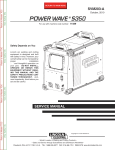
![[ITA] CE100-3 GSM BUS Software v1-0](http://vs1.manualzilla.com/store/data/006155765_1-5803b8585b34946e04bd1ea77a17f0e6-150x150.png)
![[in corso ENG] CE100-3 GSM BUS Software v2-2](http://vs1.manualzilla.com/store/data/006160500_1-aebd3939f48385c2811bca37393b4bbd-150x150.png)

![[ITA] CE100-3 GSM BUS Installatore v2-3](http://vs1.manualzilla.com/store/data/006159930_1-9d06e4e7e5f60baa2ba82323b792300c-150x150.png)