1
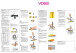
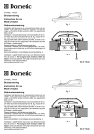
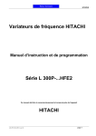
PTAC CONTROL BOARD KIT
RSKP0006
INSTALLATION INSTRUCTIONS
Description
Electrostatic Discharge (ESD) Precautions
Control board installation procedures are described in detail
in these instructions. Read and follow these instructions
carefully before replacing the control board. Failure to do so
may result in control board damage.
Before removing the new control board from the static wrap,
it is very important to discharge any static electricity. This
can be accomplished in two methods. Servicer can wear a
ground strap or by touching the metal chassis before replacing the board.
Existing Control Board Removal Procedures
1. Disconnect power to the unit by unplugging the power
cord at the wall outlet or subbase, or disconnect power at
the fuse box or circuit breaker.
2. If the cabinet front is screwed to the chassis, remove the
1/4” screw (or screws) located behind the inlet grille. Pull
the inlet grille forward from the top of the grille to access
screw(s).
Important Note:
Damage to the control board can occur from failure to
disconnect power supply or failure to set the master switch
(located on the control board) to OFF before removing the
low voltage terminal strip cover from an installed control
board. Damage to this board by not following these instructions is considered misuse and not covered under either the
standard unit warranty or any extended service contract.
FRONT MOUNTING
HOLE
Important Note:
Figure 1
All warranty replaced boards must be returned to the parts
source from which they were purchased to insure proper
warranty credit.
RECOGNIZE THIS SYMBOL AS A SAFETY PRECAUTION.
ATTENTION INSTALLING PERSONNEL
As a professional installer you have an obligation to know the product better than the customer. This
includes all safety precautions and related items.
Prior to actual installation, thoroughly familiarize yourself with this Instruction Manual. Pay special attention
to all safety warnings. Often during installation or repair it is possible to place yourself in a position which is
more hazardous than when the unit is in operation.
Remember, it is your responsibility to install the product safely and to know it well enough to be able to
instruct a customer in its safe use.
Safety is a matter of common sense...a matter of thinking before acting. Most dealers have a list of specific
good safety practices...follow them.
The precautions listed in this Installation Manual are intended as supplemental to existing practices.
However, if there is a direct conflict between existing practices and the content of this manual, the
precautions listed here take precedence.
IO-660A
November 2006
Printed in USA
3. Remove cabinet front from chassis by tilting the bottom of
the front forward, lifting slightly up and forward.
12. The external transformer will come with the Black 37
wires connected to the LOAD terminal of the transformer
(LOAD terminals are the low voltage terminals) and the
Grey 22 wire connected to the COM terminal on the
transformer. The Grey 21 wire will need to be connected
to the 230 or 265 volt tap on the transformer. Place the
control panel back on its hinges.
4. If a remote thermostat or any low voltage accessory is
being used, remove the low voltage pin connector from the
low voltage terminal strip. If a previous version board is
being replaced remove wires from the low voltage terminal
strip.
NOTE: Refer to the serial plate for voltage information.
PULL TO REMOVE
MODE SWITCH KNOB
13. Install the new board and reinstall the screws removed in
step # 8.
ESCUTCHEON
PULL TO REMOVE
THERMOSTAT KNOB
14. Using the insulated terminals connect the two (2) Black
37 wires from the Load terminals on the transformer to the
“24VAC Transformer” terminals on the control board. See
Figure 4.
3
2
1
Lift Off
ON
SCREW (2)
15.Connect Grey 22 wire from the COM terminal on the
transformer to line 2 on the control board. Connect Grey
21 wire from the transformer to line 1 on the control board.
SCREW
TRANSFORMER
Figure 2
5. Remove knobs and escutcheon.
6. Remove the two mounting screws, one on each side of
control board cover. Some models may have a screw on
the lower right side of the control panel that will need to be
removed. Tilt control panel out and remove cover.
7. Remove the wires from the board in the unit, including
Thermistor Sensors if they plug into the board.
8. Remove the four screws holding the board and remove the
old board.
Figure 3
LOAD
New Control Board Installation Procedures
TRANSFORMER
LINE
COM
265
230
BK37
GY22
GY21
BK37
LINE 1
HEATER 1
HEATER 2
9. If existing unit has a remote mounted “off board” transformer for board power, proceed to Step 13.
24VAC~TRANSFORMER
12VA CLASS 2 ONLY
10. Lift the control panel up so the control panel is free of its
hinges. Orient the control panel so there is easy access
for mounting components to the inside of the control
panel.
11. Using the two #8 screws that are provided, screw the
transformer that was provided with the kit to the control
panel in the transformer mounting holes provided in the
panel. See Figure 3.
Figure 4
2
LINE 2
COMPRESSOR
16. Thermistor Temperature Sensors Installation
A3. Replace the heater panel, routing the yellow wire
around the right end of the heater panel and into the
control panel pulling snug to prevent the wire from
being entangled in the blower wheel or being visible
from above. Replace the two screws mounting the
heater panel to the evaporator coil.
A. It is recommended that the Indoor Discharge Thermistor (with the YELLOW wires) be installed but it is
optional. If you chose not to install this sensor, the
green status light will remain illuminated continuously. For status light functionality, the YELLOW
thermistor MUST be installed. Instructions are as
follows:
A4. Replace the exhaust grille and two mounting screws.
A5. Connect the yellow wire using the plug-on connector
to the new board on the IDT (yellow) terminals.
A1. Carefully cut and remove the gasket on the left and
right sides of discharge screen. Remove the two (2)
5/16” screws holding the indoor exhaust screen above
the indoor coil. Remove the indoor exhaust screen.
B. If the existing Indoor Ambient Thermistor (with the
BLACK wires) was connected to the board by a plugon connector, reconnect it to the new board on the IAT
(black) terminals. If the existing Indoor Coil Thermistor was soldered to the previous board, install the
new black thermistor per Figure 6 and connect as
above.
Remove the two (2) 1/4” screws connecting the heater
panel to the evaporator coil.
Remove the two (2) screws mounting the air baffle to
the top of the heater panel and remove and discard the
air baffle.
A2. Install the new air baffle. Route the yellow thermistor
probe from right to left through the wiring tube enclosure. Mount the black tip of the yellow thermistor
probe in the plastic clip provided. Hold the plastic
clamp in place and secure the clamp to the left end of
heater panel using one of the original screws. Replace the screw on the right end of the air baffle being
careful not to damage the wiring insulation on the
probe.
CLAMP END OF
THERMISTOR
SECURELY
Clip is designed to be pushed
into the coil between
the aluminum fins
and attach over
two (2) screws.
PLASTIC CLAMP
WIRE ENCLOSURE
YELLOW
THERMISTOR
ROUTE THERMISTOR
THROUGH TUBE ON
BLOWER EXTENSION
Figure 6
Figure 5
3
C. If the existing Indoor Coil Thermistor (with the RED
wires) was connected to the board by a plug-on
connector, reconnect it to the new board on the ICT
(red) terminals. If the previous board used indoor coil
bi-metals, remove and discard the bi-metal devices.
The access door will need to be removed on the indoor
coil to gain access to the bi-metal. See Figure 6. The
Indoor Coil Thermistor will need to clip on the vertical
section of the 90-degree bend of the inlet line to the
indoor coil. See Figure 7. Connect the Indoor Coil
Thermistor to the board as noted above.
Cross over tube
for 9,12 and 15k
or center tube for
7,000 BTU
D. If the existing Outdoor Coil Thermistor (with the
BLUE wires) was connected to the board by a plugon connector, reconnect it to the new board on the
OCT (blue) terminals. If the previous board used
indoor coil bi-metals, remove and discard the bi-metal
devices. The Indoor Coil Thermistor will need to clip on
the crossover tube shown in Figure 8. There will be
two clips supplied in the kit for the Blue Thermistor.
One clip as supplied on the sensor will fit 5/16” tubing
used on the bent coil, and an additional clip (loose in
the bag) will fit 3/8” tubing used on the flat slab coil.
If you have a slab coil, you will need to remove the 5/16”
clip from the sensor and replace it with the 3/8” tube
clip. Connect the Outdoor Coil Thermistor to the board
as noted above. Outdoor Coil Thermistors are only
used on Heat Pump models; DO NOT INSTALL THIS
SENSOR IF THE UNIT IS NOT A HEAT PUMP.
Figure 8
17. If the unit has a condensate pump, go to step 18. If the unit
has a power vent or power door, go to step 19. Otherwise
proceed with step 20. Refer to wiring diagrams in back of
manual.
18. Condensate Pump Units Only
(See Wiring Diagram Page 10
Reconnect the wires across the top terminals of the
control board. Connect as follows:
Red 33 to Line 1
Brown 34 to Heater 1
Brown 34 to Heater 2
Power cord (or black 18) to Line 2
Violet 12 and Yellow 3 to Compressor
Black 16 to Fan High
Red 17 to Fan Low
19 from reversing valve and Yellow 1 to Rev. Valve.
Connect the yellow 5 wire to the 230 or 265-volt terminal
as applicable using the piggyback terminal on the yellow
5 wire. Go to step 21.
Figure 7
INDOOR COIL THERMISTOR - RED
All Units
Connect to ICT on Control Board
4
22. If a remote thermostat or any low voltage accessory is
being used connect the low voltage pin connector to low
voltage terminal strip.
19. Power Vent/Power Door Units Only
(See Wiring Diagram Page 9)
Reconnect the wires across the top terminals of the
control board. Connect as follows:
If replacing a previous version board you will need to use
the 18 pin connector supplied with the board for low
voltage accessories. Wires supplied with this kit have
terminal ends on the wires. Insert the terminal end into
the correctly labeled slot, push in and it will lock in place.
After loading pin connector use the wire nuts supplied
with the kit to wire nut the new wires onto the existing
wires supplied for low voltage accessories. See Figure 9
on page 5.
Red 33 to Line 1
Brown 34 to heater 1
Brown 34 to Heater 2
Power cord (or black 18) to Line 2
Violet 12 to Compressor
Blue 4 to Fan high
23. Set the master switch to ON. Restore electrical power
and verify unit functionality.
Blue 15 and Blue 10 to Fan Low
19 from reversing valve to Rev. Valve
24. This control can be configured for several operational
features.
Connect the white 7 wire to the 230 or 265-volt terminal as
applicable using the piggyback terminal on the white 7
wire. Go to step 21.
A. If the unit was being controlled by a wired wall
thermostat, the board will have to be configured to
allow the thermostat to operate the unit. To configure
for a wired wall thermostat, press and hold the FAN
SPEED button and press the COOL button twice. The
light in the bottom left hand corner below the OFF light
will blink twice to confirm that the configuration was
successful. Repeat step 24 if the light did not blink.
20. Reconnect the wires across the top terminals of the
control board. Connect as follows:
(See Wiring Diagram Page 8)
Red 33 to line 1
Brown 34 to heater 1
Brown 34 to heater 2
B. If the unit will be controlled by a wireless thermostat
(Goodman DS01A using DT01A antenna on the unit),
the board may have to be configured to allow the
wireless thermostat to operate the unit. To configure
for wireless operation, press and hold the FAN SPEED
button and press the HEAT button twice. The light in
the bottom left hand corner below the OFF light will
blink twice to confirm that the configuration was
successful. Repeat step 24 if the light did not blink.
Power cord or black 18 to line 2
Violet 12 to compressor
Black 16 to Fan High
Red 17 to Fan Low
19 from reversing valve to Rev. Valve.
21. If a remote wired thermostat and an additional REK01B
escutcheon that states “THIS UNIT IS CONTROLLED BY
WALL MOUNTED THERMOSTAT” is used, the knob and
potentiometer will need to be removed. To remove the
knob, loosen the set screw on the side of the knob with
a flat screwdriver and pull knob from potentiometer shaft.
To remove the potentiometer, loosen the nut with a 10mm
driver and remove the nut and 2 washers. Pull the shaft
free of the panel. Reassemble potentiometer, washers,
nut and knob and store for future use. These will be
required if the unit is ever converted back to local controls
instead of wired thermostat operation.
C. If constant fan is desired, the unit will need to be
configured by pressing and holding the HEAT button
and pressing the OFF button twice. To revert to auto/
cyclic fan operation, press and hold the COOL button
and press the OFF button twice.
D. Other configuration items exist, but can only be
accessed over the wireless antenna to a wireless site
platform (Goodman DP01A).
E. To reset all the configuration items back to the factory
defaults, turn the master switch off for 10 seconds,
and then hold the HEAT and COOL button while
turning the master switch back on.
The control board cover is now ready to be installed. The
ribbon for the touch pad will need to be connected to the
control board. Take caution not to bend or fold the
ribbon (See Figure 9 for ribbon connection).
25. Replace the front in reverse order as removed in Steps 2
and 3.
Install orange connector from the thermostat on the touch
pad to the IHD Terminals on control board, unless the
knob has been removed.
Ensure that no wires are pinched or caught between the
cover and the panel and then reinstall the screws removed
in Step 5.
5
Remote Thermostat
*Only load wires needed for accessories attached to unit.
Figure 9
6
GREEN w/YELLOW STRIPE
BLUE
YELLOW
WHITE
GREEN
RED
YELLOW w/BLACK STRIPE
BLACK w/WHITE STRIPE
BROWN
Figure 10
7
LINE 1
Left is ON
Position
ON
24VAC-TRANSFORMER
DSI
IN
GL
RIBBON CONNECTOR
FAN
HIGH
B
FAN
LOW
GH
BLACK
REV.
VALVE
YELLOW
RED
BLUE
Heat Pump models ONLY.
Must not be used
on PTC models.
ORANGE from Touch Pad
YELLOW
WIRING DIAGRAMS
REMOTE THERMOSTAT OPERATION
COOLING UNIT
W/ELECTRIC HEAT
FUNCTION
HEAT PUMP W/AUXILIARY
ELECTRIC HEAT
CONNEC
CONNECT
R TO:
OFF
-----
FAN
G
COOL
CONNEC
CONNECT
R TO:
FUNCTION
G
FAN
COOL
*
HEAT
WIRING DIAGRAM
205180 REV.0
-----
OFF
G, Y/W1
1ST STAGE
ANTICIPATOR
CURRENT: .1
2ND STAGE
ANTICIPATOR
CURRENT: .1
G, Y/W1
1ST STAGE
HEAT
G,B,Y/W1
2ND STAGE
HEAT
G, W2
* FOR A HEAT PUMP
THERMOSTAT USED
ON A STRAIGHT
COOL UNIT
C
H
F
OD
FAN/COMP
CAP
YL10
RD13
R
C
BR14
RIBBED
WIRE
2
G
N
1
WH15
20
LOAD
TRANSFORMER
ELECTRIC
HEATER
COM
265
230
FUSE
FAN
MOTOR
RE V
VALVE
SOLENOID
5
7
RD33
3
BK18
RD17
BR34
GY21
BR34
GY22
VT12
BK16
COMPRESSOR
FAN
HIGH
19
X2
X1
BK37
BK37
LINE 1
HEATER 2
HEATER 1
LINE 2
FAN
LOW
REV
VALVE
X3
X4
E1
E2
E3
E4
E5
E6
E8
E7
E9
K1
E10
K3
K2
K4
K5
IDT
YELLOW
E11
K6
GREEN
P1
P2
E12
CP4
ORANGE
P5
P9
ICT
RED
P8
OCT
BLUE
CR11
P4
24VAC~TRANSFORMER
12VA CLASS 2 ONLY
SW2
P10
M1
P11
COM A
P13
M2
COM B
ON / OFF
MASTER SWITCH
DS1 DS2 MS1 MS2 EH IN LS FD1 FD2 TF - TF+ C R GL W2 Y/W1 B GH
REMOTE THERMOSTATE
AUXILIARY
IAT
BLACK
6
HIGH VOLTAGE!
DISCONNECT ALL POWER BEFORE SERVICING OR INSTALLING THIS
UNIT. MULTIPLE POWER SOURCES MAY BE PRESENT. FAILURE TO
DO SO MAY CAUSE PROPERTY DAMAGE, PERSONAL INJURY OR DEATH.
COMP
S
NOTES:
1
WARNING:
ARNING: DISCONNECT POWER BEFORE SERVICING. W IRING
TO UNIT MUST BE PROPERLY POLARIZED (FOR 265
5V)) AND GROUNDED.
2
RIBBED WIRE MUST BE CONNECTED AS SHOWN
3
ON HEAT PUMP MODELS ONLY.
4
ON UNITS W ITH FRONT DESK CONTROL SWITCH.
5
6
4
FRON T
DESK
SWITCH
USE COPPER
CONDUCTORS ONLY
CHASSIS
BK18 ON LINE 2 WITH FUSE SHOWN CONNECTED FOR 265V. FOR 230V & 11 5 V, CONNECT
POWER CORD TO LINE 2.
FOR REMOTE OPERATION, SEE CONFIGURATION CHART.
7
IF SUPPLY VOLTAGE IS 208V/230V USE THE 230V TAP ON TRAN SFORMER.
IF SUPPLY VOLTA GE IS 265V USE THE 265V TAP ON TR ANSFORMER.
115V TRANSFORMER NOT SHOWN.
8
FOR CONTINUOS FAN OPERATION SEE CONFIGURATION CHART.
GN
1
CONTRO L
PANEL
WIRE LEGEND
HIGH VOLTAGE
(FACTORY)
HIGH VOLTAGE
(FACTORY OR FIELD)
LOW VOLTAGE
(FACTORY OR FIELD)
8
WIRING DIAGRAMS
1ST STAGE
ANTICIPATOR
CURRENT: .1
2ND STAGE
ANTICIPATOR
CURRENT: .1
REMOTE THERMOSTAT OPERATION
HEAT PUMP W/AUXILIARY
ELECTRIC HEAT
COOLING UNIT
W/ELECTRIC HEAT
CONNECT
R TO:
FUNCTION
CONNECT
R TO:
FUNCTION
OFF
-----
OFF
-----
FAN
G**
FAN
G**
G, Y/W1
COOL
G, Y/W1
COOL
*
HEAT
WIRING DIAGRAM
20518101 REV 0
POWER
VE N T
MO TOR
* FOR A HEAT PUMP
THERMOSTAT USED
ON A STRAIGHT
COOL UNIT
POWER
VENT
MUFFIN
FAN
** GL- low speed
GH- high speed
1ST STAGE
HEAT
G,B,Y/W1
2ND STAGE
HEAT
G, W2
6
208
240
F
C
H
CO M
LINE
OD
FAN/COMP
CAP
YL10
WH8
(PV)
BK11
(PV)
BR14
RD13
BU9
(PV)
COMP
WH15
8
9
265
CO M
A
ON/OFF
SWITCH
B
20
WH7
(PV)
BK17
(PV)
FAN
MO TOR
1
BU2
(PV)
BK12
(PV)
GN
1
7
RD14
(PV)
8
LINE
230
BU4
(PV)
BU10
(PV)
BK16
RD17
TERMINAL
BLOCK
RD33
5
REV
VALVE
SOLENOID
ELECTRIC
HEATER
3
BU15
(PV)
BK18
BK37
19
BK37
GY21
BR34
BR34
HEATER 1
HEATER 2
VT12
GY22
X2
X1
LINE 1
X3
E1
E2
LINE 2
FAN
HIGH
COMPRESSOR
FAN
LOW
REV
VALVE
X4
E3
E4
E5
E6
E8
E7
K1
E9
E10
K2
K3
K4
K5
IDT
YELLOW
E11
K6
GREEN
P1
P2
E12
P4
CP4
P5
P9
ICT
RED
P8
OCT
BLUE
CR11
ORANGE
24VAC~TRANSFORMER
12VA CLASS 2 ONLY
SW2
P10
M1
P11
COM A
P13
M2
COM B
ON / OFF
MASTER SWITCH
DS1 DS2 MS1 MS2 EH IN LS FD1 FD2 TF- TF+ C R GL W2 Y/W1 B GH
REMOTE THERMOSTATE
AUXILIARY
IAT
BLACK
7
HIGH VOLTAGE!
DISCONNECT ALL POWER BEFORE SERVICING OR INSTALLING THIS
UNIT. MULTIPLE POWER SOURCES MAY BE PRESENT. FAILURE TO
DO SO MAY CAUSE PROPERTY DAMAGE, PERSONAL INJURY OR DEATH.
R
C
RIBBED
WIRE
3
6
2
2
2
5
3
S
1
4
4
NOTES
1
:
2
WARNING: DISCONNECT POWER BEFORE SERVICING. WIRING
TO UNIT MUST BE PROPERLY POLARIZED (FOR 265V) AND GROUNDED.
RIBBED WIRE MUST BE CONNECTED AS SHOWN.
3
ON HEAT PUMP MODELS ONLY.
4
ON UNITS WITH FRONT DESK CONTROL SWITCH.
5
BK18 ON LINE 2 WITH FUSE SHOWN CONNECTED FOR 265V. FOR 230V AND 115V, CONNECT
POWER CORD TO LINE 2.
6
IF SUPPLY VOLTAGE IS 208V MOVE 240V LEAD TO 208V TAP ON TRANSFORMER.
265V AND 115V TRANSFORMER NOT SHOWN .
7
FOR REMOTE OPERATION, SEE CONFIGARATION CHART.
8
FRON T
DESK
SWITCH
USE COPPER
CONDUCTORS ONLY
CHASSIS
GN
1
CONTRO
CONTROL
PANEL
WIRE LEGEND
HIGH VOLTAGE
(FACTORY)
IF SUPPLY VOLTAGE IS 208V/230V USE THE 230V TAP ON TRANSFORMER.
I F SUPPLY VOLTAGE IS 265V USE THE 265V TAP ON TRANSFORMER.
1 15V TRANSFORMER NOT SHOWN.
HIGH VOLTAGE
(FACTORY OR FIELD)
LOW VOLTAGE
(FACTORY OR FIELD)
9FOR CONTINUOS FAN OPERATION SEE CONFIGURATION CHART.
9
WIRING DIAGRAMS
1ST STAGE
ANTICIPATOR
CURRENT: .1
2ND STAGE
ANTICIPATOR
CURRENT: .1
REMOTE THERMOSTAT OPERATION
COOLING UNIT
W/ELECTRIC HEAT
HEAT PUMP W/AUXILIARY
ELECTRIC HEAT
CONNECT
R TO:
FUNCTION
CONNECT
R TO:
FUNCTION
OFF
-----
OFF
-----
FAN
G
FAN
G
COOL
G, Y/W1
COOL
*
HEAT
WIRING DIAGRAM
205184 REV 0
* FOR A HEAT PUMP
THERMOSTAT USED
ON A STRAIGHT
COOL UNIT
G, Y/W1
1ST STAGE
HEAT
G,B,Y/W1
2ND STAGE
HEAT
G, W2
F
C
H
OD
FAN/COMP
CAP
YL10
BR14
RD13
1
3
2
4
5
6
A
B
S
2
R
OR8
(CP)
C
RIBBED
WIRE
20
WH15
6
LINE
208
240
COM
G
N
1
FAN
MOTOR
8
WH 6
(CP)
208
VT12
BK16
5
RD33
BR34
GY21
REV
VALVE
SOLENOID
ELECTRIC
HEATER
COM
LINE
240
3
RD17
19
BK18
BR34 YL5
(CP)
GY22
YL3
(CP)
BK37
YL1
(CP)
BK37
X2
X1
LINE 1
HEATER 2
HEATER 1
LINE 2
FAN
HIGH
COMPRESSOR
FAN
LOW
REV
VALVE
X3
X4
E1
E2
E3
E4
E5
E6
E7
E8
K1
E9
E10
K3
K2
K4
K5
IDT
YELLOW
E11
K6
GREEN
P1
P2
E12
CP4
ORANGE
P5
P9
ICT
RED
P8
OCT
BLUE
CR11
P4
24VAC~TRANSFORMER
12VA CLASS 2 ONLY
SW2
P10
M1
P11
COM A
P13
M2
COM B
ON / OFF
MASTER SWITCH
DS1 DS2 MS1 MS2 EH IN LS FD1 FD2 TF- TF+ C R GL W2 Y/W1 B GH
REMOTE THERMOSTATE
AUXILIARY
IAT
BLACK
7
HIGH VOLTAGE!
DISCONNECT ALL POWER BEFORE SERVICING OR INSTALLING THIS
UNIT. MULTIPLE POWER SOURCES MAY BE PRESENT. FAILURE TO
DO SO MAY CAUSE PROPERTY DAMAGE, PERSONAL INJURY OR DEATH.
COMP
4
FRONT
DESK
SWITCH
NOTES
2
WARNING: DISCONNECT POWER BEFORE SERVICING. WIRING
TO UNIT MUST BE PROPERLY POLARIZED (FOR 265V) AND GROUNDED.
RIBBED WIRE MUST BE CONNECTED AS SHOWN.
3
ON HEAT PUMP MODELS ONLY.
4
ON UNITS WITH FRONT DESK CONTROL SWITCH.
5
BK18 ON LINE 2 WITH FUSE SHOWN CONNECTED FOR 265V. FOR 230V AND 115V, CONNECT
POWER CORD TO LINE 2.
6
IF SUPPLY VOLTAGE IS 208V MOVE 240V LEAD TO 208V TAP ON TRANSFORMER.
265V AND 115V TRANSFORMER NOT SHOWN.
FOR REMOTE OPERATION, SEE CONFIGURATION CHART.
1
7
8
USE COPPER
CONDUCTORS ONLY
IF SUPPLY VOLTAGE IS 208V, MOVE 204V LEAD TO 208V TAP ON TRANSFORMER.
265V AND 115V TRANSFORMER NOT SHOWN.
9
CHASSIS
GN
1
CONTROL
PANEL
WIRE LEGEND
HIGH VOLTAGE
(FACTORY)
HIGH VOLTAGE
(FACTORY OR FIELD)
FOR CONTINUOS FAN OPERATION SEE CONFIGURATION CHART.
LOW VOLTAGE
(FACTORY OR FIELD)
10
THIS PAGE LEFT INTENTIONALLY BLANK
11
Quality Makes the Difference!
All of our systems are designed and manufactured with the same high quality standards regardless of size or
efficiency. We have designed these units to significantly reduce the most frequent causes of product failure.
They are simple to service and forgiving to operate. We use quality materials and components. Finally, every
unit is run tested before it leaves the factory. That’s why we know. . .There’s No Better Quality.
Visit our website at
www.amana-ptac.com for information on:
•
•
•
•
•
•
Products
Warranties
Customer Services
Parts
Contractor Programs and Training
Financing Options
is a trademark of Maytag Corporation and is used under
license to Goodman Company, L.P. All rights reserved.
®
Goodman Company, L.P.
2550 North Loop West, Suite 400
Houston, TX 77092
© 2006 Goodman Company, L.P.
12