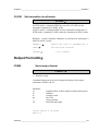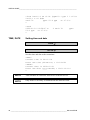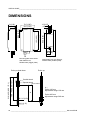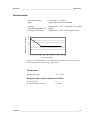
1
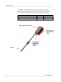
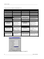
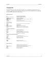
USER'S GUIDE
®
Vaisala HUMICAP Moisture and
Temperature Transmitter Series for Oil
MMT310
M210474EN-B
PUBLISHED BY
Vaisala Oyj
P.O. Box 26
FIN-00421 Helsinki
Finland
Phone (int.): +358 9 8949 1
Fax:
+358 9 8949 2227
Visit our Internet pages at http://www.vaisala.com/
© Vaisala 2008
No part of this manual may be reproduced in any form or by any means, electronic or
mechanical (including photocopying), nor may its contents be communicated to a third
party without prior written permission of the copyright holder.
The contents are subject to change without prior notice.
Please observe that this manual does not create any legally binding obligations for
Vaisala towards the customer or end user. All legally binding commitments and
agreements are included exclusively in the applicable supply contract or Conditions of
Sale.
________________________________________________________________________________
Table of Contents
CHAPTER 1
GENERAL INFORMATION............................................................................ 3
About This Manual ................................................................... 3
Version Information ............................................................... 3
General Safety Considerations ............................................. 3
Feedback............................................................................... 4
Product Related Safety Precautions ...................................... 4
ESD Protection ......................................................................... 4
Recycling .................................................................................. 5
Regulatory Compliances ......................................................... 5
Trademarks ............................................................................... 5
License Agreement .................................................................. 5
Warranty.................................................................................... 7
CHAPTER 2
PRODUCT OVERVIEW.................................................................................. 9
Introduction to MMT318 and MMT317 .................................... 9
CHAPTER 3
MOUNTING .................................................................................................. 11
Selecting a place for the probe............................................. 11
Mounting the transmitter/Removing the transmitter unit .. 12
Mounting the MMT318............................................................ 13
Mounting for Pressurized Pipelines/Oils ............................. 13
Ball Valve Installation Kit for MMT318 ................................. 14
Tightening the Clasp Nut..................................................... 15
Mounting the MMT317 ........................................................ 17
MMT317 with Swagelok Connector for Tight-place
Installations ......................................................................... 17
CHAPTER 4
WIRING......................................................................................................... 21
CHAPTER 5
OPERATION................................................................................................. 23
Power ON/OFF ........................................................................ 23
Giving the serial communication parameters ..................... 23
Measurement output .............................................................. 26
Output Formatting.................................................................. 29
VAISALA_____________________________________________________________________ 1
USER'S GUIDE____________________________________________________________________
Setting, scaling and testing the analog outputs .................32
Calibration and adjustment ...................................................34
Preparations before the calibration .....................................35
Relative humidity calibration and adjustment
(in two points) ......................................................................35
Temperature calibration and adjustment (in one point).......38
Error states..............................................................................40
Other commands ....................................................................41
CHAPTER 6
MAINTENANCE............................................................................................45
Changing the filter and sensor..............................................45
Clean the sensor before storing the MMT318 and
MMT317....................................................................................45
Factory calibration and repair service .................................45
Technical Support ..................................................................46
Return Instructions ................................................................46
Vaisala Service Centers .........................................................47
CHAPTER 7
TECHNICAL SPECIFICATIONS ..................................................................49
Accessories.............................................................................51
DIMENSIONS ...............................................................................................52
MMT317 with optional Swagelok Connector, Dimensions.54
APPENDIX 1
APPLICATIONS ...........................................................................................55
Transformer oils .....................................................................55
Ppm-calculation for transformer oils....................................56
Paper machine application ....................................................60
List of Tables
Table 1
Manual Revisions .......................................................................3
2 ________________________________________________________________ M210474EN-B
Chapter 1 ________________________________________________________ General Information
CHAPTER 1
GENERAL INFORMATION
This chapter provides general notes for the manual and the product.
About This Manual
This manual provides information for installing, operating, and
maintaining MMT318 and MMT317.
Version Information
Table 1
Manual Code
M21047EN-A
M21047EN-B
Manual Revisions
Description
MMT318 User's Guide
MMT318 and MMT317 User's Guide. The manual
has been updated with MMT317 installation
instructions and MMT317 dimension figure.
General Safety Considerations
Throughout the manual, important safety considerations are
highlighted as follows:
WARNING
Warning alerts you to a serious hazard. If you do not read and follow
instructions very carefully at this point, there is a risk of injury or
even death.
VAISALA_____________________________________________________________________ 3
USER'S GUIDE____________________________________________________________________
CAUTION
Caution warns you of a potential hazard. If you do not read and
follow instructions carefully at this point, the product could be
damaged or important data could be lost.
NOTE
Note highlights important information on using the product.
Feedback
Vaisala Customer Documentation Team welcomes your comments
and suggestions on the quality and usefulness of this publication. If
you find errors or have other suggestions for improvement, please
indicate the chapter, section, and page number. You can send
comments to us by e-mail: [email protected]
Product Related Safety Precautions
The MMT318 and MMT317 delivered to you has been tested for
safety and approved as shipped from the factory. Note the following
precautions:
WARNING
Ground the product, and verify outdoor installation grounding
periodically to minimize shock hazard.
CAUTION
Do not modify the unit. Improper modification can damage the
product or lead to malfunction.
ESD Protection
Electrostatic Discharge (ESD) can cause immediate or latent damage
to electronic circuits. Vaisala products are adequately protected
against ESD for their intended use. However, it is possible to damage
the product by delivering electrostatic discharges when touching,
removing, or inserting any objects inside the equipment housing.
4 ________________________________________________________________ M210474EN-B
Chapter 1 ________________________________________________________ General Information
To make sure you are not delivering high static voltages yourself:
- Handle ESD sensitive components on a properly grounded and
protected ESD workbench. When this is not possible, ground
yourself to the equipment chassis before touching the boards.
Ground yourself with a wrist strap and a resistive connection cord.
When neither of the above is possible, touch a conductive part of
the equipment chassis with your other hand before touching the
boards.
- Always hold the boards by the edges and avoid touching the
component contacts.
Recycling
Recycle all applicable material.
Dispose of batteries and the unit according to statutory regulations.
Do not dispose of with regular household refuse.
Regulatory Compliances
The MMT318 and MMT317 comply with the following performance
and environmental test standards:
Trademarks
Microsoft®, Windows®, Windows NT®, and Windows® 2000 are
registered trademarks of Microsoft Corporation in the United States
and/or other countries.
License Agreement
All rights to any software are held by Vaisala or third parties. The
customer is allowed to use the software only to the extent that is
VAISALA_____________________________________________________________________ 5
USER'S GUIDE____________________________________________________________________
provided by the applicable supply contract or Software License
Agreement.
6 ________________________________________________________________ M210474EN-B
Chapter 1 ________________________________________________________ General Information
Warranty
Vaisala hereby represents and warrants all Products
manufactured by Vaisala and sold hereunder to be
free from defects in workmanship or material
during a period of twelve (12) months from the date
of delivery save for products for which a special
warranty is given. If any Product proves however to
be defective in workmanship or material within the
period herein provided Vaisala undertakes to the
exclusion of any other remedy to repair or at its
own option replace the defective Product or part
thereof free of charge and otherwise on the same
conditions as for the original Product or part
without extension to original warranty time.
Defective parts replaced in accordance with this
clause shall be placed at the disposal of Vaisala.
Vaisala also warrants the quality of all repair and
service works performed by its employees to
products sold by it. In case the repair or service
works should appear inadequate or faulty and
should this cause malfunction or nonfunction of the
product to which the service was performed Vaisala
shall at its free option either repair or have repaired
or replace the product in question. The working
hours used by employees of Vaisala for such repair
or replacement shall be free of charge to the client.
This service warranty shall be valid for a period of
six (6) months from the date the service measures
were completed.
This warranty is however subject to following
conditions:
a) A substantiated written claim as to any alleged
defects shall have been received by Vaisala
within thirty (30) days after the defect or fault
became known or occurred, and
b) The allegedly defective Product or part shall,
should Vaisala so require, be sent to the works
of Vaisala or to such other place as Vaisala may
indicate in writing, freight and insurance
prepaid and properly packed and labelled,
unless Vaisala agrees to inspect and repair the
Product or replace it on site.
This warranty does not however apply when the
defect has been caused through
a) normal wear and tear or accident;
b) misuse or other unsuitable or unauthorized use
of the Product or negligence or error in storing,
maintaining or in handling the Product or any
equipment thereof;
c) wrong installation or assembly or failure to
service the Product or otherwise follow
Vaisala's service instructions including any
repairs or installation or assembly or service
made by unauthorized personnel not approved
by Vaisala or replacements with parts not
manufactured or supplied by Vaisala;
d) modifications or changes of the Product as well
as any adding to it without Vaisala's prior
authorization;
e) other factors depending on the Customer or a
third party.
Notwithstanding the aforesaid Vaisala's liability
under this clause shall not apply to any defects
arising out of materials, designs or instructions
provided by the Customer.
This warranty is expressly in lieu of and excludes
all other conditions, warranties and liabilities,
express or implied, whether under law, statute or
otherwise, including without limitation any implied
warranties of merchantability or fitness for a
particular purpose and all other obligations and
liabilities of Vaisala or its representatives with
respect to any defect or deficiency applicable to or
resulting directly or indirectly from the Products
supplied hereunder, which obligations and
liabilities are hereby expressly cancelled and
waived. Vaisala's liability shall under no
circumstances exceed the invoice price of any
Product for which a warranty claim is made, nor
shall Vaisala in any circumstances be liable for lost
profits or other consequential loss whether direct or
indirect or for special damages.
VAISALA_____________________________________________________________________ 7
USER'S GUIDE____________________________________________________________________
8 ___________________________________________________________________ M210474EN-B
Chapter 2 __________________________________________________________ Product Overview
CHAPTER 2
PRODUCT OVERVIEW
This chapter introduces the features, advantages, and the product
nomenclature.
Introduction to MMT318 and MMT317
Vaisala HUMICAP® moisture in oil transmitter MMT318 and
MMT317 are designed for industrial applications. The MMT318 and
MMT317 transmitter measure water in oil in terms of water activity
(aw) which can be determined as follows: water activity indicates the
amount of oil in the scale of 0 - 1 aw. In this scale, 0 aw is an
indication of completely water free oil and 1 aw an indication of oil
fully saturated with water. Water is present in free form. The water
activity is used for alarming at the point of > 0.9 aw where the risk for
free water is obvious.
The most advanced feature which distinguishes the measurement of
water activity (aw) from the traditional measurement of absolute water
content (in ppm) is that the in the water activity measurement
saturation point remains stable regardless of the oil type, aging of oil
or additives used. As water activity of the oil exceeds 0.9 aw, there is
a risk for segregation (especially if the temperature decreases).
The MMT318 and MMT317 transmitters can be used for continuous
on-line measurements and it can be calibrated against salt solutions,
no reference oils are needed.
Appendix presents application information when using the MMT318
and MMT317 with transformer oil (output unit= ppm). General
information on paper machine use is also included in the Appendix.
VAISALA ________________________________________________________________________ 9
USER'S GUIDE____________________________________________________________________
The MMT318 and MMT317 powers up with 24 VDC. Output
alternatives are analog outputs 0/4... 20mA and RS232C serial line.
The transmitter measures and calculates the following quantities:
Quantity
aw water activity
T Temperature
ppm (for transformer oil only)
Metric Unit
aw
°C
ppm
Non Metric Unit
aw
°F
ppm
Removable transmitter unit
Mounting plate
(two alternative
sizes)
Connector for
signal output
and power
supply
Probe
10 __________________________________________________________________ M210474EN-B
Chapter 3 _________________________________________________________________Mounting
CHAPTER 3
MOUNTING
Selecting a place for the probe
Select a place which gives a true picture of the process. Oil should
circulate freely around the sensor; clear oil flow is recommended.
Install the probe directly into the circulation system and not into the
oil reservoir because of deposition.
It is recommended that the sensor head is installed directly in the
process through the ball valve assembly. When the ball valve
assembly is used, the pipe does not have to be emptied or shut down
for installation or removal of the probe. Install the sensor head
transversely against the direction of the process flow.
NOTE
NOTE
Avoid mounting the transmitter housing close to steam sources
or directly exposed to rain. To ensure an IP 65 class protection.
Always mount the transmitter housing with the cable bushings
pointing downwards.
Take care not to damage the pipe of the probe. If
the pipe is damaged, the probe head is less tight
and will not go through the clasp nut. Make sure
that the filter is tightly fastened to protect the
sensors.
VAISALA _______________________________________________________________________ 11
USER'S GUIDE____________________________________________________________________
Mounting the transmitter/Removing the
transmitter unit
1. Mount the plate onto the wall by using four/two screws (∅4.5 mm/6.0 mm).
2. Place the transmitter onto the mounting plate and fasten it by using two allen
screws.
The transmitter module can be unfastened for calibration by releasing two allen
screws on the left side.
Two screw holes (∅
6.0 mm) on the base of
the plate for wall
mounting (screws not
provided)
Four screw holes (∅
4.5 mm) for wall
mounting
(screws not provided)
Two allen screws for
fastening/removing the
transmitter module
(allen key provided)
Mounting with bigger mounting plate
NOTE
Mounting with smaller mounting plate
It is recommended that the supply is switched off, before connecting the
cable plug to transmitter during installation or service/calibration.
12 __________________________________________________________________ M210474EN-B
Chapter 3 _________________________________________________________________Mounting
Mounting the MMT318
NOTE
Do not unsolder and then again resolder the sensor head cable from
and to the printed board during installation; this procedure may alter
the humidity calibration of the transmitter.
Mounting for Pressurized Pipelines/Oils
Due to the sliding fit, the MMT318 is easy to install into and remove from the
pressurized process. The probe is especially suitable for the measurements in
pipelines.
1
2
1. clasp nut, 24 mm hex nut
2. fitting body, 27 mm hex head
MMT318 pipe dimensions (in mm); standard 178 (adjustment range 120
mm) and optional 400 mm (adjustment range 340 mm).
Adjust the probe to a suitable depth according to the type of installation and
tighten the clasp nut first manually. Mark the fitting body and the clasp nut.
Tighten the nut a further 50 - 60° (ca.1/6" turn) with a fork spanner. If you have a
suitable torque spanner, tighten the nut to 45±5 Nm (33±4 ft-lbs). Be careful not
to over tighten' the nut.
When the probe is used in a pressurized processes the sensor head should
preferebly be installed through a ball valve assembly.
VAISALA _______________________________________________________________________ 13
USER'S GUIDE____________________________________________________________________
CAUTION Take care not to damage the probe body. A damaged body makes
the probe head less tight and may prevent it from going through the
clasp nut.
Use teflon tape or thread sealant to seal the connection between the
fitting body and the process/ ball valve, see Figure below.
Ball Valve Installation Kit for
MMT318
The ball valve installation kit (Vaisala order code: BALLVALVE-1)
is preferred when connecting the probe to a pressurized process or
pipeline. Use the ball valve set or a 1/2" ball valve assembly with a
ball hole of Ø14 mm or more. If you install the sensor head (Ø 12
mm) in a process pipe, please note that the nominal size of the pipe
must be at least 1 inch (2.54 cm). Use the manual press handle to press
the sensor head into the pressurized (< 10 bar) process or pipeline.
1.
Shut down the process if the process pressure is more than 10
bars. If the pressure is lower there is no need to shut down the
process.
2.
Make the installation according to the figure below. Install the
sensor head transversely against the direction of the process
flow.
14 __________________________________________________________________ M210474EN-B
Chapter 3 _________________________________________________________________Mounting
You can not close the valve if the groove (7) is not in sight. When
installing the sensor head through the Ball Valve Assembly it is not
necessary to empty or shut down the process for installing or
removing the sensor head.
1.
Mount the probe with the ball valve assembly closed; tighten the
clasp nut manually. Add tape or other sealing according to
instructions, see figure on page 14.
2.
Open the ball valve assembly.
3.
Push the probe head through the ball valve assembly into the
process. If the pressure is high, use a manual press handle. Note
that the sensor head must be pushed so deep that the filter is
completely inside the process flow.
4.
Tighten the clasp nut a further 50-60º.
Tightening the Clasp Nut
1.
Adjust the probe to a suitable depth according to the type of
installation.
2.
Tighten the clasp nut first manually.
3.
Mark the fitting body and the clasp nut.
4.
Tighten the nut a further 50 -60º (ca. 1/6 turn) with a wrench. If
you have suitable torque spanner, tighten the nut to max 45 ± 5
Nm (33 ± 4 ft-lbs).
1
2
3
max . 60°
4
0511-109
Tightening the Clasp Nut
The following numbers refer to above:
1
2
3
=
=
=
Probe
Clasp nut
Pen
VAISALA _______________________________________________________________________ 15
USER'S GUIDE____________________________________________________________________
The following numbers refer to above:
4
=
Fitting body
NOTE
Take care not to over tighten the clasp nut to avoid difficulties when
opening it.
CAUTION
Take care not to damage the probe body. A damaged body makes the
probe head less tight and may prevent it from going through the clasp
nut.
CAUTION
In pressurized processes it is essential to tighten the supporting nuts
and screws very carefully to prevent loosening of the probe by the
action of pressure.
Stage 1
Stage 2
6
1. probe
1
2. Tighten first manually;
probe is then sliding easily.
Finally tighten with a spanner
about 60° more, to have a
stable installation, Note: do not
overtighten this screw!.
7
2
3
3. handle of the ball valve
4. ball of the ball valve
3
Valve
closed
4
5. process chamber / pipeline
6. manual press tool
5
7. the groove on the probe
indicates the upper adjustment
limit
16 __________________________________________________________________ M210474EN-B
Chapter 3 _________________________________________________________________Mounting
NOTE
It is recommended that the supply is switched off, before connecting the
cable plug to the transmitter during installation or service/calibration.
Mounting the MMT317
The MMT317 has a small pressure-tight probe and it is ideal for tight
spaces with threaded connection. The small probe is installed using
the threaded fitting bodies, see below.
NOTE
Do not unsolder and then again resolder the sensor head cable from
and to the printed board during installation; this procedure may alter
the humidity calibration of the transmitter.
MMT317 with Swagelok Connector
for Tight-place Installations
Swagelok installation kit for the MMT317 includes Swagelok
connector with ISO3/8" thread ( Vaisala order code: SWG12ISO38)
or NPT1/2" thread (Vaisala order code: SWG12NPT12). See figure
below for MMT317 with Swagelok Installation Kit.
VAISALA _______________________________________________________________________ 17
USER'S GUIDE____________________________________________________________________
The following numbers refer to figure MMT317 Probe Installation to
Pipeline with Swagelok Installation Kit above:
1
2
3
4
5
6
7
1.
=
=
=
=
=
=
=
Probe
Duct connector
ISO3/8" or NPT1/2" thread
Swagelok connector
Ferrules
Upper edge of the connector nut
Upper edge of the probe
Preparing Installation. The connector options are the following:
a.
R3/8" ISO (Swagelok code SS-12M0-1-6RTBT)
b.
1/2" NPT (Swagelok code SS-12M0-1-8BT)
Note that the connector inner diameters extend for Ø12 mm probe.
2.
Probe position. Before the final tightening check that the upper
edge of the connector nut is in line with the upper edge of the
probe. Otherwise the sealing may not be gas tight.
3.
Gas tight sealing
a.
Turn the connector nut finger tight and draw a vertical
mark on the nut and the fitting body.
b.
Be sure that the probe position follows step 2.
c.
Tighten the connector nut with a wrench 1 and 1/4 turns
(360º +90º) with the help of marks you drew. The
connector has now a gas tight connection to the probe.
Excess tightening can damage the probe.
18 __________________________________________________________________ M210474EN-B
Chapter 3 _________________________________________________________________Mounting
d.
Connector can be disconnected and re-installed. In reinstallation first turn the connector nut finger tight and
then with wrench 1/4 turn (90º).
Use teflon tape or thread sealant to seal the connection between the
Swagelok connector and the process, see figure below.
VAISALA _______________________________________________________________________ 19
USER'S GUIDE____________________________________________________________________
This page intentionally left blank.
20 __________________________________________________________________ M210474EN-B
Chapter 4 ___________________________________________________________________ Wiring
CHAPTER 4
WIRING
When the MMT318 and MMT317 leave the factory, their measurement ranges,
output scaling and quantities have already been set according to order completed
by a customer. The unit is calibrated at the factory and the device is ready for use.
Transmitter is delivered with screw terminal connector or with detachable 5m
cable with eight wires for serial port, analog outputs and 24VDC power supply.
See the wiring instructions below.
Cable wiring
5 GREY (GND)
Cable color codes and functions:
1 White
RS232C TX
2 Brown
RS232GND
6 PINK (+24VDC)
3 Green
CH2+.
4 Yellow
CH1+.
5 Grey
Supply-/CH1-/CH2 7 BLU (RX)
6 Pink
Supply +24VDC
7 Blue
RS232C RX
1 WHT (TX)
8 Red
Not connected
4 YEL (CH1+)
3 GRN (CH2 +)
2 BRN (RS232GND)
8 RED (NOT CONNECTED)
Screw terminal connector
Cable codes and functions:
1
RS232C TX
2
RS232GND
3
CH2+.
4
CH1+.
5
Supply- /CH1-/CH2 6
Supply +24VDC
7
RS232C RX
8
Not connected
5
6
4
7
3
1
2
8
VAISALA _______________________________________________________________________ 21
USER'S GUIDE____________________________________________________________________
22 __________________________________________________________________ M210474EN-B
Chapter 5 ________________________________________________________________ Operation
CHAPTER 5
OPERATION
Power ON/OFF
Switch ON the power supply 24VDC and the transmitter turns on.
Giving the serial communication parameters
The transmitter communicates via an RS232C serial interface. The transmitter can be polled
or set on run mode with specific commands.
The data format will be (factory settings):
- 1 Start Bit
- 7 Data Bits
- 1 Stop Bit
- Even Parity
- 4800 bits per second, programmable to 19200
- Full Duplex
- Serial Asynchronous
- Configured as Data Terminal Equipment (DTE)
Give the communication parameters when using this terminal session for the first time; save
them for future use. See instructions in the following tables.
VAISALA _______________________________________________________________________ 23
USER'S GUIDE____________________________________________________________________
Giving parameters in Windows 95 and Windows NT
WINDOWS 95
MENU
Start
Ø
Programs
Ø
Accessories
Ø
HyperTerminal
Ø
Hypertrm
WHAT TO DO
move the cursor to:
move the cursor to:
move the cursor to:
click
move the cursor to:
double click
Ø
Connection
Description
WINDOWS NT
MENU
Start
Ø
Programs
Ø
Accessories
Ø
WHAT TO DO
move the cursor to:
move the cursor to:
move the cursor to:
HyperTerminal
Ø
Hyperterminal
move the cursor to:
click
Ø
type the name of the
connection in the
appropriate field and
select an icon if
available; click OK.
Connection
Description
type the name of the
connection in the
appropriate field and
select an icon if
available; click OK.
Ø
Phone Number
move the cursor to the
field CONNECT USING
and select 'direct to
COM x' (x = serial port
available); click OK
Ø
COM x properties
Connect to
move the cursor to the
field CONNECT USING and
select 'COM x' (x =
serial port available);
click OK
Ø
select parameters
according to the
previous figure; click
OK
COM x properties
select parameters
according to the previous
figure, click OK
Selecting the parameters in Windows 95 and NT.
24 __________________________________________________________________ M210474EN-B
Chapter 5 ________________________________________________________________ Operation
Commands
The bold text in the brackets is a default setting. Give commands by typing them on your
computer. ↵ stands for pressing ENTER. This page presents the command list, the commands
are described in details later in this chapter.
Measurement output
R
S
INTV [0…255 S/MIN/H]
SEND [0…99]
SMODE [STOP/RUN/POLL]
SERI [baud p d s]
ADDR [0…99]
CLOSE
OPEN [0…99]
Starting the continuous outputting
Stopping the continuous outputting
Setting the continuous output interval
Outputting the reading once
Setting the serial interface
Serial line settings (default: 4800 E 7 1) baud: 300…19200
Setting the address
Closing the line to POLL mode
Opening temporarily connection to the POLL-mode device
Output formatting
FORM
DATE
TIME
FDATE [ON/OFF]
FTIME [ON/OFF]
UNIT
Setting the output format of SEND and R commands
Entering the date
Setting the time
Adding date to R and SEND outputs
Adding time to output to SEND and R outputs
Selecting the metric or non-metric output units
Calibration and adjustment
CDATE
CRH
CT
CTEXT
FCRH
LI
Setting the calibration date
Relative humidity calibration
Temperature calibration
Giving the text to calibration information field
Relative humidity calibration after sensor change
Reverting the factory calibration
Setting and testing the analog outputs
AMODE
ASEL
ASCL
ITEST
Setting the analog outputs
Selecting the parameter for the analog outputs
Scaling the analog outputs
Testing the analog outputs
Error states
ERRS
AERR
Listing the error messages
Changing the analog error output value
Other commands
?
??
ECHO [ON/OFF]
FIND
FILT
RESET
Outputting the information about the device
Outputting the information about the device in POLL-state
Turning the serial interface echo ON/OFF
All devices in POLL mode send their addresses
Setting the result filtering
Resets the transmitter
VAISALA _______________________________________________________________________ 25
USER'S GUIDE____________________________________________________________________
Measurement output
R
Starting the continuous outputting
R↵
Starts output of measurements to the peripheral devices (RUN mode);
the only command that can be used is S (stop).
The output mode can be changed with command FORM.
Example:
>r
aw=
aw=
S
0.2000 aw T=
0.2000 aw T=
25.09 'C …
25.20 'C …
Stopping the continuous outputting
S↵
Stops the continuous output. Also <ESC> can be used to stop
outputting.
INTV
Setting the continuous outputting interval for the
RUN mode
INTV xxx yyy ↵
xxx=
yyy=
output interval (0...255)
unit (s, min or h)
Example:
>intv 1
Output interval: 1 S
>intv 1 min
Output interval: 1 MIN
>intv 1 h
Output interval: 1 H
26 __________________________________________________________________ M210474EN-B
Chapter 5 ________________________________________________________________ Operation
SEND
Outputting the reading once
In STOP mode:
SEND ↵
In POLL mode:
SEND aa ↵
aa = address of the transmitter when more than one transmitter is
connected to a serial bus (0...99)
Example.
>send
aw=
0.2 aw T=
-47.37 'C …
If value is too long to fit to the allocated space or if there is an error in
outputting, value is displayed with stars ‘*’.
For example,
aw=*.* aw T= 31.0 'C
The output mode can be changed with command FORM.
SMODE
Setting the serial interface mode
SMODE x↵
X= STOP/RUN/POLL
STOP MODE: Transmitter in standby for serial commands.
RUN MODE: Transmitter outputs data continuosusly.
POLL MODE: Transmitter only responds to addressed commands
>smode run
Output mode
: RUN
>r
02:08:01.03 aw=
02:08:04.21 aw=
<ESC>
>smode stop
Output mode
0.2 aw T=
0.2 aw T=
-47.13 'C …
-47.16 'C …
: STOP
VAISALA _______________________________________________________________________ 27
USER'S GUIDE____________________________________________________________________
SERI
Serial line settings
SERI b p d s ↵
b = bauds (300, 600, 1200, 2400, 4800, 9600,19200)
p = parity (n = none, e = even, o = odd)
d = data bits (7 or 8)
s = stop bits (1 or 2)
The settings can be changed one parameter at a time or all parameters
at once:
>SERI O ↵
4800 O 7 1
>SERI 600 N 8 1 ↵
600 N 8 1
ADDR
changing parity only
changing all parameters
Setting the transmitter address for use in POLL-mode.
ADDR aa ↵
aa = address (0...99)
Example:
>addr
Address
>addr 1
Address
OPEN
: 0
: 1
Temporarily opens transmitter from POLL-mode to
receive serial commands
OPEN nn ↵
nn = address of the transmitter (0...99)
The OPEN command sets the bus temporarily in STOP mode so that
the SMODE command can be given.
Example:
open 4
Device:
>
4 line opened for operator commands
28 __________________________________________________________________ M210474EN-B
Chapter 5 ________________________________________________________________ Operation
CLOSE
Set transmitter in poll-mode
CLOSE ↵
In STOP mode: command OPEN has no effect, CLOSE sets the
transmitter temporarily in POLL mode
In POLL mode: command OPEN sets the transmitter temporarily in
STOP mode, command CLOSE returns the instrument to POLL mode
Example: relative humidity calibration is performed at transmitter 2
which is in POLL mode
>OPEN 2 ↵
>CRH ↵
...
>CLOSE ↵
opens the line to transmitter 2
calibration started
line closed
Output Formatting
FORM
Serial output format
FORM x ↵
x = formatter string
Command format can be used to change the format of the output
commands ‘SEND’ and ‘R’.
Modifiers:
x.y
#t
#r
#n
“”
U5
length modifier (whole numbers and decimal places)
tabulator
carridge-return
line feed
string constant
unit field and lenght
>form "aw="1.2 aw #r#n
aw=0.79
VAISALA _______________________________________________________________________ 29
USER'S GUIDE____________________________________________________________________
>form "aw="1.2 aw U3 #t "ppm="3.1 ppm " " U5 #t
"T="3.1 T U3 #r#n
aw=0.78
ppm= 53.4 ppm
T= 27.3'C
>
>send
2000-01-01 20:56:27 N
53.2 ppm
T= 27.2'C
>
TIME, DATE
0 aw=0.78
ppm=
Setting time and date
TIME ↵
DATE ↵
Sets the time and date to the transmitter.
TIME↵
Current time is 04:12:39
Enter new time (hh:mm:ss) ? 12:24:00↵
>DATE↵
Current date is 2000-01-01
Enter new date (yyyy-mm-dd) ? 2001-12-11↵
>
NOTE
Time and date are cleared to 2000-01-01 00:00:00 at reset.
NOTE
Only about 1% accuracy is obtained with the software clock.
30 __________________________________________________________________ M210474EN-B
Chapter 5 ________________________________________________________________ Operation
FTIME, FDATE
Adding time and date to R and SEND outputs
FTIME x ↵
FDATE x ↵
x = ON or OFF
Command will enable/disable output of time and date to the serial
line.
>send
aw= 0.2 aw T= 31.0 'C
>ftime on
Form. time
: ON
>send
03:47:59 aw= 0.2 aw T= 31.0 'C
>fdate on
Form. date
: ON
>send
2000-01-01 03:48:03 aw= 0.2 aw T= 31.0 'C
>
UNIT
Selecting metric or non-metric output units
UNIT x ↵
x = M or N
M = metric units
N = non-metric units
*
Quantity
aw
T
ppm*
Metric Unit
°C
ppm
Non Metric Unit
°F
ppm
for transformer oil only
VAISALA _______________________________________________________________________ 31
USER'S GUIDE____________________________________________________________________
Setting, scaling and testing the analog outputs
You can select for the two outputs
-
current range (0...20 mA/4...20 mA) and
output parameter (aw/ ppm*/ T).
and scale the two outputs according to your needs.
*
AMODE
for transformer oil only
Setting the analog outputs (0...20 mA/4...20 mA)
AMODE ch1 ch2 ↵
where ch1 and ch2:
I0 = 0...20 mA
I1 = 4... 20 mA
>amode i1 i1↵
Ch1 output mode: 4...20mA
Ch2 output mode: 4...20mA
>
If the output includes a reminder 'remember to set jumpers', please
ignore the reminder.
ASEL
Selecting the parameter for the analog outputs
ASEL xxx yyy ↵
where: xxx = quantity of channel 1 and yyy = quantity of channel 2.
Use abbreviations shown in the table below.
Quantity
aw water activity
T Temperature
ppm (for transformer oil only)
abbreviation
aw
T
ppm
Examples:
>asel aw t
Ch1 aw
lo
:
0.00
?
32 __________________________________________________________________ M210474EN-B
Chapter 5 ________________________________________________________________ Operation
Ch1 aw
hi
Ch2 T
lo
Ch2 T
hi
>asel t ppm
Ch1 T
lo
Ch1 T
hi
Ch2 ppm lo
Ch2 ppm hi
>
*
ASCL
:
:
:
:
:
:
:
1.00
-40.00 'C
60.00 'C
-40.00
60.00
0.00
5000.00
'C
'C
ppm
ppm
?
?
?
?
?
?
?
ppm calculation only for transformer oils
Scaling the analog outputs
ASCL ↵
Example:
>ascl
Ch1 T
Ch1 T
Ch2 ppm
Ch2 ppm
>ascl
Ch1 T
Ch1 T
Ch2 ppm
Ch2 ppm
*
ITEST
lo
hi
lo
hi
:
:
:
:
-40.00
60.00
0.00
5000.00
'C
'C
ppm
ppm
?
?
?
?
lo
hi
lo
hi
:
:
:
:
-20.00
40.00
0.00
3000.00
'C
'C
ppm
ppm
?
?
?
?
-20
40
0
3000
ppm calculation only for transformer oils
Testing the analog outputs
The operation of the analog outputs are tested by forcing the outputs
to given values. The values in the analog outputs can then be
measured with a current/voltage meter.
ITEST aa.aaa bb.bbb ↵
where:
aa.aaa = current value to be set for channel 1
bb.bbb = current value to be set for channel 2
mA
VAISALA _______________________________________________________________________ 33
USER'S GUIDE____________________________________________________________________
For example:
>ITEST 8
12 ↵
8.000mA 3F8 12.000mA
>
70O
The set values remain valid until you give the command ITEST
without readings or RESET the transmitter.
AQTEST
Testing the analog outputs for desired readings
Use command ‘AQTEST’ to test current values of desired aw or T
readings. Current output is forced to correspond the chosen values.
AQTEST x yyy.yyy ↵
where:
x = aw / T / ppm
yyy.yyy = value
For example:
>AQTEST aw 0.5↵
CH1 aw :
0.5000 aw
CH2 T
:
22.3 'C
>
10.000mA
7.568mA
The set values remain valid until you give the command AQTEST
without a value or RESET the transmitter.
Calibration and adjustment
The MMT318 and MMT317 are calibrated as shipped from the
factory. Typical calibration interval is one year. Depending on the
application it may be good to make the first calibration check earlier.
Calibration of the MMT318 and MMT317 can be carried out by the
user according to the instructions given in this chapter.
The device can also be sent to Vaisala for calibration. See Vaisala
Service Centers' contact information on page 47.
34 __________________________________________________________________ M210474EN-B
Chapter 5 ________________________________________________________________ Operation
Relative humidity calibration must be done always after sensor
change.
Preparations before the calibration
Before the calibration the used sensor should be cleaned with
instrument air to blow out existing oil or gently first flush with
heptane (C7H14 16) and dry with instrument air to decrease response
time.
The claning shall be done as the dirty sensor can contamine the salt
bath and change the reference condition.
NOTE
It is important to clean the sensor before calibration as the dirty
sensor can contamine the salt bath and change the reference
condition.
Relative humidity calibration and adjustment
(in two points)
Relative humidity calibration and adjustment of the MMT318 and
MMT317 is done by using two reference humidities, difference
between the two humidity references must be at least 50% RH.
An easy calibration can be done by using Vaisala Humidity Calibrator
HMK15. If using HMK15 calibrator, please use the adapter fitting
(13.5 mm) with the MMT318 and MMT317 probe.
Before calibrations the MMT318 and MMT317 must be set to
adjustment mode by pressing once the adjustment button, see picture.
VAISALA _______________________________________________________________________ 35
USER'S GUIDE____________________________________________________________________
Adjustment button
Low end adjustement
1.
Remove the transmitter unit from the mounting plate (see page
12), and press the adjustment button once, see picture.
2.
Remove the filter from the probe and insert the probe head into
a measurement hole of the dry end reference chamber (e.g. LiCl:
11 % RH in the humidity calibrator HMK15, please use the
adapter fitting (13.5 mm)).
3.
Wait at least 30 minutes for the sensor to stabilize.
4.
Give command CRH and press ENTER.
CRH ↵
Type C and press ENTER a few times to check if the reading is
stabilized.
5. When the reading is stabilized, give the reference humidity after
the question mark and press ENTER.
>crh
RH :
11.25 Ref1 ? c
RH :
11.25 Ref1 ? c
RH :
11.25 Ref1 ? c
RH :
11.24 Ref1 ? c
RH :
11.24 Ref1 ? 11.3
Press any key when ready ...
Now the device is waiting for the high end reference.
36 __________________________________________________________________ M210474EN-B
Chapter 5 ________________________________________________________________ Operation
High end adjustement
6. After having made the low end adjustment, insert the probe head
into a measurement hole of the high end reference chamber (e.g.
NaCl: 75 % RH chamber in the humidity calibrator HMK15, please
use the adapter fitting (13.5 mm)). Please, note that the difference
between the two humidity references must be at least 50% RH.
7. Let the probe stabilize at least 30 minutes. You can follow the
stabilization by pressing any key, typing C and pressing ENTER.
8. When stabilized, type the high end reference value after a question
mark and press ENTER.
>crh
RH :
11.25 Ref1 ? c
RH :
11.24 Ref1 ? c
RH :
11.24 Ref1 ? 11.3
Press any key when ready ...
RH
RH
RH
RH
OK
>
OK
:
:
:
:
75.45
75.57
75.55
75.59
Ref2
Ref2
Ref2
Ref2
?
?
?
?
c
c
c
75.5
indicates that the calibration has succeeded
9. Take the probe out of the reference conditions and replace the
filter. Take care to tighten the filter properly, recommended force
130 Ncm.
10. If needed, give the calibration information (date and text) to the
transmitter's memory, see the serial commands on page 29.
11. Reset the transmitter by giving a command RESET. Transmitter
returns to normal mode.
VAISALA _______________________________________________________________________ 37
USER'S GUIDE____________________________________________________________________
Temperature calibration and
adjustment (in one point)
1.
Remove the transmitter unit from the mounting plate (see page
12) and press the adjustment button, see page 26 .
2.
Remove the probe filter and insert the probe head into the
reference temperature.
3.
Let the sensor stabilize.
4.
Type command CT and press ENTER.
CT ↵
5.
6.
Type C and press ENTER a few times to check if the reading is
stabilized.
When the reading is stabilized, give the reference temperature
after the question mark and press ENTER three times.
>ct
>
OK
T
:
16.06 Ref1 ? c
T
:
16.06 Ref1 ? c
T
:
16.06 Ref1 ? c
T
:
16.06 Ref1 ? c
T
:
16.06 Ref1 ? c
T
:
16.06 Ref1 ? 16.0
Press any key when ready ...
T
:
16.06 Ref2 ?
OK
indicates that the calibration has succeeded
7.
Take the probe out of the reference conditions and replace the
filter. Take care to tighten the filter properly, recommended
force 130 Ncm.
8.
If needed, give the calibration information (date and text) to the
transmitter's memory, see the serial commands on page 29.
9.
Reset the transmitter by giving a command RESET. Transmitter
returns to normal mode.
38 __________________________________________________________________ M210474EN-B
Chapter 5 ________________________________________________________________ Operation
LI
Reverting the factory calibration
1. Remove the transmitter unit from the mounting plate (see page 12)
and press the adjustment button, see page 26.
2. Type command LI and give value 0 for an offset value and value 1
for a gain value.
LI ↵
>li
RH offset
RH gain
T offset
T gain
>
:
:
:
:
-0.6000000
1.00000000
0.00000000
0.40000000
?
?
?
?
0
1
0
1
3. Reset the transmitter by giving a command RESET. Transmitter
returns to normal mode
FCRH
Relative humidity calibration after sensor change
FCRH ↵
The transmitter asks and measures relative humidity and calculates the
calibration coefficients. This 2-point adjustment should be performed
after a sensor change. Follow the more detailed calibration
instructions on page 35, but instead of giving CRH command, use
FRCH command.
>FCRH ↵
RH :
1.82
1. ref ?
0
↵
Press any key when ready...
↵
RH :
74.22
2. ref ? 75 ↵
OK
>
The OK indicates that the calibration has succeeded.
CTEXT
Giving text to calibration information field
CTEXT ↵
VAISALA _______________________________________________________________________ 39
USER'S GUIDE____________________________________________________________________
Set calibration info text.
CTEXT↵
Cal. info
>
CDATE
: Vaisala/HEL ? HMK15↵
Giving date to calibration information field
CDATE yyyy mm dd↵
Set calibration date.
CDATE 2001 12 11
Calibration
: 2001-12-11
>
Error states
ERRS
Displaying the error messages
ERRS ↵
Display transmitter error messages. If there are no errors present, a
PASS is returned.
Example 1:
>ERRS
PASS
>
Example 2:
>ERRS
FAIL
Error: Temperature measurement malfunction
Error: Humidity sensor open circuit
>
40 __________________________________________________________________ M210474EN-B
Chapter 5 ________________________________________________________________ Operation
In case of constant error, please contact Vaisala Service Centers, see
page 47.
AERR
Setting the error outputs
Factory default state for analog outputs during error condition is 0
mA. Please be careful when selecting the new error value, the error
state of the transmitter should not cause problems in process
monitoring.
AERR ↵
Example:
>aerr
Ch1 error out
Ch2 error out
>
: 0.000mA ?
: 0.000mA ?
NOTE
Error output value must be within a valid range for output type.
NOTE
The error output value is shown only when there are minor electrical
faults such as a humidity sensor open circuit. When there is a severe
device malfunction, like analog output electronics failure or
microprocessor ROM/RAM failure, the error output value is not
necessarily shown.
Other commands
?
Checking transmitter settings
Use command ‘?’ to check the current transmitter configuration.
Command ‘??’ is similar, but can also be used if the transmitter is in
POLL state.
?↵
?? ↵
VAISALA _______________________________________________________________________ 41
USER'S GUIDE____________________________________________________________________
Example (factory default settings):
>?
HMT310 / 1.03
PRB serial nr : V1234567
Calibration
: 2003-03-25
Cal. info
: NU/HMK15
Output units
: metric
Pressure
: 1013.25 hPa
RS232 settings
Address
: 2
Output interval: 1 MIN
Baud P D S
: 4800 E 7 1
Serial mode
: STOP
Analog outputs
Ch1 output mode: 0 ...20mA
Ch2 output mode: 4 ...20mA
Ch1 error out : 0.000mA
Ch2 error out : 0.000mA
Ch1 T
lo
:
-40.00 'C
Ch1 T
hi
:
60.00 'C
Ch2 ppm lo
:
0.00 ppm
Ch2 ppm hi
: 5000.00 ppm
>
ECHO
Serial bus echo
ECHO x ↵
x = ON or OFF (default=ON)
Use commands to enable/disable echo of characters received over the
serial line.
FIND
All devices in POLL mode are sending their
addresses.
FIND ↵
HELP
Listing the commands.
HELP ↵
42 __________________________________________________________________ M210474EN-B
Chapter 5 ________________________________________________________________ Operation
FILT
Setting the result filtering
Configure type of filtering that will be used for all outputs.
FILT xx↵
where: xx = OFF, ON or EXT
OFF = No filtering (default)
ON = Short filter of about 15 s (results the average value of the last 15
s measurement data).
EXT = Extended filter of about 1min (results the average value of the
last 1 min measurement data).
RESET
Resets the transmitter
RESET ↵
VAISALA _______________________________________________________________________ 43
USER'S GUIDE____________________________________________________________________
This page intentionally left blank.
44 __________________________________________________________________ M210474EN-B
Chapter 6 ______________________________________________________________ Maintenance
CHAPTER 6
MAINTENANCE
Changing the filter and sensor
1. Unscrew the filter from the probe head.
2. Remove the damaged sensor and insert a new one. Handle the
sensor by the plastic socket. DO NOT TOUCH THE SENSOR
PLATE.
3. After sensor change the humidity calibration must be made
according to the instructions, see command FCRH, page 29 .
4. Screw a new filter on the probe head. Take care to tighten the filter
properly, recommended force 130 Ncm.
New sensors and filters can be ordered from Vaisala, see list of
accessories on page 51.
Clean the sensor before storing the MMT318
and MMT317
Clean the used sensor with instrument air to blow out existing oil or
gently first flush with heptane (C7H14 16) and dry with instrument air
to prevent oxidation of the sensor. The oxidation of the sensor can
cause extended response times or drifting.
Factory calibration and repair service
The MMT318 and MMT317 are fully calibrated as shipped from
factory. The recommended calibration interval is 1 year. However,
calibration shall be done always when there is a reason to believe that
VAISALA _______________________________________________________________________ 45
USER'S GUIDE____________________________________________________________________
device is not within the accuracy specifications. The MMT318 and
MMT317 can be calibrated and adjusted by a user (see page 34 ) or it
can be sent to Vaisala for calibration and adjustment.
Technical Support
For technical questions, contact the Vaisala technical support:
E-mail
[email protected]
Fax
+358 9 8949 2790
Return Instructions
If the product needs repair, please follow the instructions below to
speed up the process and to avoid extra costs to you.
1.
Read the section Warranty on page 7.
2.
Contact a Vaisala Service Center or a local Vaisala
representative. The latest contact information and instructions
are available from www.vaisala.com. Addresses of the Service
Centers are provided in section Vaisala Service Centers on page
47.
Please have the following information on hand:
- serial number of the unit
- date and place of purchase or last calibration
- description of the fault
- circumstances in which the fault occurs/occurred
- name and contact information of a technically competent
person who can provide further information on the problem
3.
Pack the faulty product in a strong box of adequate size, with
proper cushioning material to avoid damage.
4.
Include the information specified in step 2 in the box with the
faulty product. Also include a detailed return address.
5.
Ship the box to the address specified by your Vaisala contact.
46 __________________________________________________________________ M210474EN-B
Chapter 6 ______________________________________________________________ Maintenance
Vaisala Service Centers
Vaisala Service Centers perform calibrations and adjustments as well
as repair and spare part services. See contact information below.
Vaisala Service Centers also offer accredited calibrations,
maintenance contracts, and a calibration reminder program. Do not
hesitate to contact them to get further information.
VAISALA _______________________________________________________________________ 47
USER'S GUIDE____________________________________________________________________
This page intentionally left blank.
48 __________________________________________________________________ M210474EN-B
Chapter 7 _____________________________________________________ Technical specifications
CHAPTER 7
TECHNICAL SPECIFICATIONS
Water activity
Measurement range
0...1 (@-40...+180 °C/ -40...+356 °F)
Accuracy (including nonlinearity and repeatability)
When calibrated against salt solutions (ASTM E104-85):
±0.02 (0...0.9)
±0.03 (0.9...1.0)
When calibrated against high-quality, certified humidity standards:
±0.01 (0...0.9)
±0.02 (0.9...1.0)
Response time (90 %) at +20 °C in
still oil (stainless steel filter)
10 min
Humidity sensor
HUMICAP®180 L2
Temperature
Measurement range
Typical accuracy at +20 °C (+68 °F)
Typical temperature dependence of electronics
Temperature sensor
-70...+180 °C (-94...+356 °F)
±0.1 °C (±0.18°F)
± 0.005 °C/°C (±0.003°F/°F)
Pt 100 RTD 1/3 Class B IEC 751
Electronical connections
Two analog oputputs
0...20 mA or 4...20 mA (selectable and
scalable)
Typical accuracy of analog output at + 20 °C(+68 °F) 0.05 % FS
Typical temperature dependence of analog outputs 0.005 %FS/°C (0.003 %F/°F)
Serial output
RS232C
VAISALA _______________________________________________________________________ 49
USER'S GUIDE____________________________________________________________________
Connections
8- pole connector where RS232C,
current outputs (two channels) and Uin
Operating voltage
Minimum operating voltages
with RS232C
with Iout 0... 20mA/4... 20 mA
24 VDC (10.... 35 VDC)
10 VDC
11 VDC + (RL/60) VDC
Power consumption @ 20 °C, Vsupply=24VDC
with RS232C
Iout 2 * 0... 20mA
20 mA
60 mA
General
Operating temperature range for electronics
Storage temperature range
Pressure range MMT317
MMT318
-40...+60 °C (-40...+140°F)
-55...+80 °C (-67...+176 °F)
0...10 bar
0...40 bar
Transmitter housing material
Transmitter base material
Housing classification
G-AlSI10Mg
ABS/PC
IP 65 (NEMA 4)
Cable feed through alternatives
-8-pole connector with 5 m cable
-Female 8-pin connector screw joint for
cable diameter 4...8 mm
Sensor protection
Stainless steel grid
Cable length
Sensor head dimensions
2, 5 or 10m
length 170/400 mm, Ø 13.5 mm:
Electromagnetic compatibility
EN 61326-1:1997 + Am1:1998 + Am 2:2001 Electrical equipment for measurement, control
and laboratory use - EMC requirements; Industrial environment.
Note! The RF -field susceptibility level according to standard EN 61000-4-3 with frequency
band 110... 165 MHz, is only 3V/m (generic environment) with the specified accuracy when
using current output.
50 __________________________________________________________________ M210474EN-B
Chapter 7 _____________________________________________________ Technical specifications
Emissions
Radiated emissions
EN55022 / CISPR16/22 Class B
Immunity
Electrostatic discharge (ESD)
Radiated immunity
EFT burst (Electric fast transients)
Surge
Conducted immunity
EN/IEC 61000-4-2
EN/IEC 61000-4-3
EN/IEC 61000-4-4
EN/IEC 61000-4-5
EN/IEC 61000-4-6
criteria B
criteria A
criteria B
criteria B
criteria A
Accessories
Accessory
Sensor
PT100 sensor
SS grid
Calibration adapter for HMK15
Ball valve set
Order code
HUMICAP180L2
10429
HM47453SP
211302
DMP248BVS
VAISALA _______________________________________________________________________ 51
USER'S GUIDE____________________________________________________________________
DIMENSIONS
72.5 (2.85)
60.5 (2.38)
12 (0.47)
102 (4.02)
115 (4.53)
Ø4.5 (0.177)
6 (0.24)
83.5 (3.29)
43 (1.69)
5 (0.20)
19 (0.75)
48.5 (1.91)
Mounting plate alternatives:
Wall Plate/Cover,
DRW212957 (bigger plate)
Probe up
Parallel thread
Tapered thread
(R1/2" ISO7/1)
A:
Probe 180 mm
adjustment range 120 mm
A
180 / 400 (7.09 / 15.7)
216 / 435 (8.50 / 17.1)
Probe pushed down
Wall Plate/Cover (No Flange),
DRW214786 (smaller plate)
Probe 400 mm
adjustment range 340 mm
Ø 13.5 (0.53)
Ø 12 (0.47)
52 __________________________________________________________________ M210474EN-B
Chapter 7 _______________________________________________________________Dimensions
Ball valve set dimensions (mm)
manual
press
tool
∅ 5.5. mm
Probe
pipe
Adjustment range
120 mm/ 340 mm
hand le
ø14
(40)
ball of the
ball valve
> 14
=
VAISALA _______________________________________________________________________ 53
USER'S GUIDE____________________________________________________________________
MMT317 with optional Swagelok Connector,
Dimensions
54 __________________________________________________________________ M210474EN-B
Appendix 1 _____________________________________________________________ Applications
APPENDIX 1
APPLICATIONS
Transformer oils
The determination of moisture in oil is an essential part of a
comprehensive transformer maintenance program. Oil immersed
transformers rely on the oil for cooling, protection from corrosion and
as an important component of their insulation. Excessive moisture
contents in oil causes accelerated ageing of the insulation materials
and reduces their dielectric strength. In extreme cases this can result in
arcing and short circuits within the windings. Accurate moisture
measurements can also warn about leaks in the oil system, as water is
absorbed from the surrounding air.
Heating and cooling of a transformer effect moisture levels in oil. This
is due to the fact that the water solubility of oil is temperature
dependent. In general, water solubility increases as temperature raises
(see Figure 1). Changes in temperature affect also on water desorption
of the paper insulation around the transformer windings. Desorption of
water from the insulation increases as temperature raises and the
surrounded oil absorbs desorbed water. Moisture level in oil is thus a
true indicator of moisture present in the paper insulation.
In addition, it must be noted that capacity of oil to absorb water
depends both on the chemical structure of the oil and the additives.
The water concentration of transformer oil is usually 0...80 ppm and
the temperature range of the oil 0...100ºC.
VAISALA _______________________________________________________________________ 55
USER'S GUIDE____________________________________________________________________
Water solubility of mineral transformer oil as a
function of temperature
WATER SOLUBILITY IN MINERAL TRANSFORMER OIL
10000
1000
average water
solubility
range of
variation due to
oil type
range of
variation due to
oil type
100
10
0
10
20
30
40
50
60
70
80
90
100
Temperature (°C)
Figure 1. The water solubility of transformer oils versus
temperature. The margins show the range of variation of water
solubility found in mineral oils.
Ppm-calculation for transformer
oils
Traditionally, moisture in transformer oil is measured by using
ppm-units. The ppm-output shows the average mass concentration
of water in oil.
The moisture and temperature transmitter MMT318 and MMT317
have an option for ppm-output provided that this has been notified as
placing the order of the transmitter.
NOTE
Silicone based oils must have the MMT318 and MMT317 with the
Calculation Model With Oil Specific Coefficients.
56 __________________________________________________________________ M210474EN-B
Appendix 1 _____________________________________________________________ Applications
Calculation Model with Average Coefficients
The calculation model of the MMT318 and MMT317 is based on
the average water solubility behaviour of transformer oils. The
ppm-output is calculated as follows:
ppm = aw × 10 (A/(T+273.16)+B)
Where
(1)
aw= water activity
A,B= coefficients (average/oil specific)
T= temperature (ºC)
Generally, measurements with MMT318 and MMT317 give accuracy
better than 10 % of the reading. If additional accuracy is needed, refer
to the paragraph Calculation Model with Oil Specific Coefficients.
Calculation Model with Oil Specific Coefficients
For additional accuracy, oil specific calculation model can be used
both for mineral and silicon based oils. An oil sample has to be sent to
Vaisala for modelling. As a result, the specific coefficients (A and B,
see formula 1) for the transformer oil are determined by Vaisala.
Using these coefficients the accuracy of measurements is increased.
The determined coefficients of the transformer oil can be programmed
to the MMT318 and MMT317 by Vaisala or by a user according to
the instructions presented on page 58 .
NOTE
Calculation Model With Oil Specific Coefficients is always needed
for silicone based oils.
VAISALA _______________________________________________________________________ 57
USER'S GUIDE____________________________________________________________________
PPM- calculation setting
OIL
Oil calculation setting (Calculation Model with Average
Coefficients
Give a command OIL ON when you are measuring moisture in oil and
you want to have ppm-output.
OIL x ↵
x= ON/OFF
Example:
>oil on
Oil ppm
>oil
Oil ppm
Oil[0]
Oil[1]
>
OIL
: ON
: ON
: -1.66269994E+03
:
7.36999989E+00
Changing the calculation coefficients (Calculation
Model with Oil Specific Coefficients)
1. Press the blue adjustment button (see picture on page 26) to enable
feeding of coefficients.
2. Give a command OIL.
OIL ↵
3. Type the first coefficient after the question mark and press
ENTER.
4. Type the second coefficient after the second question mark and
press ENTER.
5. Reset the transmitter by giving the command RESET Turn off and
on the power to return the transmitter to the normal mode.
Example:
>oil
Oil ppm
Oil[0]
Oil[1]
>
: ON
: -1.66269994E+03
:
7.36999989E+00
?
?
58 __________________________________________________________________ M210474EN-B
Appendix 1 _____________________________________________________________ Applications
Technical data
Typical measuring
range
0...80* ppm (0...100ºC)
*Upper edge limited to saturation
Accuracy
(Calculation Model with
Average Coefficients)
Temperatures > 30 ºC: better than 10 % of the
reading
Temperatures < 30ºC: see the figure below.
Maximum error of the reading (%)
20
18
16
14
12
10
8
6
4
2
0
0
10
20
30
40
50
60
70
80
90
100
Te m pe r atur e (de g C)
Figure 2. The maximum errors caused by deviation of mineral oils using
calculation model with average coefficients.
Temperature
Measurement range
-40...+180ºC
Response times (with stainless steel filter)
In still air (20ºC)
In still transformer oil (20ºC)
10 s
< 10 min
VAISALA _______________________________________________________________________ 59
USER'S GUIDE____________________________________________________________________
Paper machine application
Typically, a paper machine contains two or three separate lubrication
systems. Usually, one is located at the wet end and the other at the dry
end. There is a certain amount of free moisture constantly present
which means that there is a risk of this moisture becoming into contact
with the machine bearings. The most common reasons for the entrance
of water are an inadequate sealing of the housing and cleaning with
high pressure. However, accidental leakages from oil coolers and
other equipment may also cause damage. In paper machines, the oil
should absorb water while lubricating the bearings and then release
this water when collected into the reservoir. It is to be noted that
bearings should never be exposed to oils that have a high water
content; this is especially important during standstill because the risk
for corrosion process increases as the oil temperature decreases. It is
essential to monitor the water content and keep it on a suitable level.
When measuring the water content of oil in paper machines, it would
be useful to measure the water activity before an oil reservoir and
from a pressure line flow. This way, the performance of dehumidifiers
can be kept under control to ensure that no free water reaches the
bearings.
60 __________________________________________________________________ M210474EN-B
www.vaisala.com