1
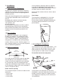
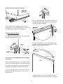
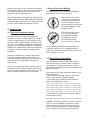
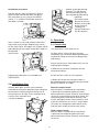
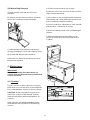
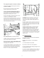
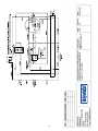
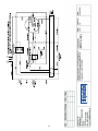
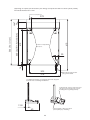
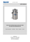
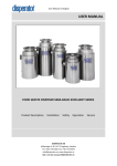
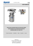
Waste Compactor Model 8075
Installation, Use & Care Guide
Start Button (with Ram Status LED)
Door Interlock
Interlock Actuator
Key Lock
Compact Mode Switch
Bag Storage Area
Odor Disk
Ram
Compaction Plate Release Tab
Compaction Plate
Trash Bucket Latches (2)
Sliding Trash Bucket
Leveling Rollers
Leveling Legs
DISPERATOR AB Mälarvägen 9, SE-141 71 Segeltorp, Sweden Tel: +46 8 724 01 60, Fax:+46 8 724 60 70
E-mail: [email protected], www.disperator.se Ref. 8075/Inst,Oper/Eng/101129
Important Safeguards
Grounding Instructions
Read all instructions carefully before operating
compactor.
1. For personal safety this compactor must be
properly grounded.
1. Do not push waste into compactor container
with hands or feet. Waste might contain broken
glass, sharp pieces of metal etc. which would
cause injury.
2. A 10Amp fuse is required for compactor Model
8075-E connected to 220-240V, 50/60Hz, AC, a
15Amp fuse for compactor Model 8075-L
connected to 115-120V, 60Hz, AC. For both these
compactor versions grounded electrical supply
is required. Time-delay fuse or circuit breaker is
recommended. It is recommended that a separate
circuit serving only this compactor be provided.
2. Do not compact volatile material. Paint, oil rags,
lighter fluid cans etc. could combust spontaneously
and cause an explosion and/or fire.
3. Do not compact aerosol cans or any other
containers still holding toxic chemicals,
insecticides or combustible contents. Fumes may
be released which are hazardous to health.
Table of Contents
Page:
1. Installation 3
4. Do not compact lighted cigarettes, cigars or
other hot or burning items.
1.1 Unpacking
1.2 Free Standing
3
5. Do not overload the compactor.
1.3 Built-in Installations
3
1.4 Levelling the Compactor
3
1.5 Door Reversing 4
2. Preparation
5
2.1 How the Compactor Works
5
7. Do not operate this compactor with an extension
cord or plub adapter.
2.2 Use of Key Lock Switch
5
2.3 Install of Odor Control Disc
5
8. Use only DISPERATOR approved accessories.
2.4 Install Waste Bag
6
3. Operation
6
3.1 Compacting
6
3.2 Compacting Tips
7
3.3 Waste Bag Removal
8
4. Maintenance
8
4.1 Cleaning
8
4.2 Troubleshooting
9
6. Be careful when removing and carrying waste
bag. Broken glass or other sharp objects may
pierce bag. Do not overload waste bag with
heavy material such as glass.
9. Do not touch moving parts.
10. Do not take this compactor apart. Incorrect
reassembly can cause electrical shock when
operated.
11. Do not operate with a damaged power cord,
plug, motor or after damage of any kind. Have the
compactor examined and all repairs made by an
authorized serviceman.
3
4.3 Warranty
5. Electrical wiring diagram
12. Unplug the compactor from electrical outlet
before servicing.
10
11
6. Drawing of fixing compactor feet (optional) 13
1. Installation
Plan to provide an electrical outlet in the opening
that meets all applicable electrical codes and
requirements. See heading “Grounding instructions”
on page 2 above for specific information.
1.1 Unpackning the Compactor
To protect the compactor mechanism the unit is
shipped from the factory with packing material in
the waste container and the compacting plate in
the down position.
Electrical outlet shall be minimum 305mm above
floor level.
Cord clamp
Return the compacting plate to the up position by:
a) attaching the provided cord set to the back of
the unit,
b) plugging the cord into an electrical outlet,
c) turning the key lock switch to the
“ON”-position, and
d) closing the door.
Once the door is closed the unit will run and the
compacting plate will travel to the up-position.
Open the door and slide out the waste container
in order to remove the packing material in the
container.
The compactor is equipped with a 1.8m long
power cord. Use the cord clamp to prevent
excess power cord from being pinched beneath
the counter during installation or service (see
picture below).
1.2 Free-standing
CORD
CLAMP
As shipped the compactor is only configured
for built-in installation. This compactor can be
converted from built-in to free-standing with the
use of a “Toe kick support” (sold separately) or
fixing plates for compactor feet (sold separately).
Caution: Failure to use the “Toe kick support” in a
free-standing installation may cause the compactor
to be unstable during operation.
1.4 Levelling the Compactor
The compactor has four adjustable levellers – two
rollers in the rear and two legs in the front. They
allow to adjust for uneven floor and also to trim
the unit up to fit an under counter installation.
1.3 Built-in Installation
TOP OF
COMPACTOR
To level the back of the compactor
FRONT OF
COMPACTOR
Two under counter mounting straps are provided
with the delivery of the compactor. Use these
straps to secure the compactor to the underside
of a counter top. Fasten the slotted end of the
straps to the compactor using the holes in the top
of the compactor cabinet with screws provided as
shown in the picture above.
Under counter opening
The compactor requires a minimum under counter
opening of:
• 381mm wide
• 876mm high
• 610mm deep
Tip the back of the compactor up and onto a
wood block. Loosen the adjusting screws only far
enough to move the rollers to a higher or lower
slot. Retighten the adjusting screws and remove
the wood block.
To level the front of the compactor
d) Turn the bracket over and install the bracket on
the opposite side of the cabinet using the same 2
screws (see above picture).
Tip the front of the compactor up and onto a
wood block. Turn the levelling legs in or out to the
desired position. Remove the wood block.
1.5 Reversing the Door
As shipped, the compactor door is hinged on the
right (when looking at the unit).
e) Use a screw driver to remove the upper hinge
pin from the trim piece and reinstall the pin on the
opposite side (see above picture).
CAP
BUSHING
Instructions for changing door to be hinged
on the left:
DOOR
a) With the door closed, use a 3/16” allen wrench
to remove the lower hinge pin (see above picture).
b) Carefully remove door by opening and sliding
the bottom of the door away from the cabinet.
c) Use a 3/16” allen wrench to remove the lower
hinge bracket from the cabinet (2 screws, see
above picture).
f) Being careful not to scratch the door, remove
the plastic door bushing and cap from the top and
2.2 Use of Key Lock Switch
bottom of the door using a small flat screwdriver.
Install the bushings on the side of the door panel
that will be hinged and install the caps on the
opposite side (see above picture).
The compactor key lock switch is provided for
protection and as a safety measure.
g) Install the door on the cabinet by inserting the
upper hinge pin into the upper door bushing while
moving the door into place. Insert the lower hinge
pin from step a) above and tighten securely.
On
On
2. Preparation
2.1 How the Compactor Works
The DISPERATOR Compactor Model 8075
compresses kitchen / galley packing waste up to
1/6 of its original volume. It will compact waste
like milk cartons, plastic bottles, containers and
jars, tin cans, wrappings, boxes etc. Waste food
and glass are not recommended for Compactor
Model 8075. DISPERATOR food waste disposers
and glass crushers are better suited for these
purposes.
On
On
When the key lock switch
is in the “OFF” position, the
compactor will not operate.
Lock the compactor and
remove the key for preventing
unauthorized persons from
tampering with it.
When the key lock switch
is in the “ON” position,
the compactor is ready
for operation. The key
can not be removed
when in the “ON” position.
NOTE: Opening the door during operation will
stop the compactor. If it is stopped during its
cycle, the compaction plate will always return up
when the door is closed.
When the compactor is started an electrically
powered compacting plate moves down into
the waste container, compresses the waste and
then returns to the up position and shuts off
automatically.
2.3 Install Odor Control Disc
With the delivery follows an odor control disc
that will last up to six months when installed in
the compactor. The odor control disc comes
packaged in a foil pouch and is activated once the
pouch is opened.
NOTE: The compacting plate travels 2/3 of the
way down into the waste container. Because of
this, the waste container must be at least 1/3 full
before notice of compression can be made.
Write dates on the odor control disc labels in the
following manner:
• When pouch is opened, write the “Activation
Date” on top of disc in space provided.
• Write dates on the GREEN month indicator
labels in the following manner:
Month 1 label “Advance date” = 1 month from “Activation date”
Month 2 label “Advance date” = 2 months from “Activation date”
Month 3 label “Advance date” = 3 months from “Activation date”
Month 4 label “Advance date” = 4 months from “Activation date”
Month 5 label “Advance date” = 5 months from “Activation date”
• Write date on the RED month indicator label in
the following manner:
Month 6 label “Replacement date” = 6 months from “Activation date”
Caution: The odor control disc contains material
that may cause moderate eye irritation. Avoid
contact with eyes. Harmful if swallowed. Wash
skin or clothing thoroughly with soap and water
after handling. Do not reuse empty foil pouch.
Installation procedure
Smooth and shape the bag
carefully. This will prevent
the bag from being torn by
the compacting plate during
operation.
Secure the bag in
place over the two
buttons on each side
of the container.
The bag has
pre-punched holes
for this purpose.
Remove the disc from the foil pouch. Swing
open the odor control disc door, and place
disc face down on tray so that the GREEN
month “1” is visible in the window when the
disc door is closed.
3. Operation
After a month has passed, rotate the disc from
right to left using a finger. Repeat every month.
On the sixth month, the label in the window will be
red, indicating that the odor control disc needs to
be replaced
after 30 days.
3.1 Compacting
The compactor is now ready to use.
For best results, always fill each new bag
completely in the container before operating the
compactor. Doing so will minimize bag pull-up
and tearing.
Please see picture on front page of this manual
and proceed as follows:
a) Slide waste container completely into the
compactor cabinet.
Replacement odor discs are available from
DISPERATOR.
b) Turn key lock switch to “ON”-position.
c) Select one of the two compact modes as
described below by pushing the compact mode
button to “Normal” or “Hold”.
2.4 Install Waste Bag
Normal compact mode
After the door is closed and the start button
is pressed, the compacting plate will travel
downward into the waste container and compact
the waste. At the bottom of the plate stroke, the
compacting plate automatically reverses and
moves upward out of the waste container. Total
cycle time will be 45 secs. or less. At the top of
the stroke, the compactor automatically shuts
itself off and is ready to receive more waste.
With the door open and the waste container
extended to the furthest position, place a bag into
the container. Fold the bag over the top rim of
the container on all sides. Press the bag into all
corners of the container and
smooth the bottom.
Hold compact mode
After the door is closed and the start button
is pressed, the compacting plate will travel
downward into the waste container and compact
the waste.
At the bottom of the compaction plate stroke, the
plate will stop.
This setting is helpful for compressing waste for
several hours until it holds its new compacted
shape. Press the start button again to reverse
the compaction plate upward out of the waste
container. At the top of the stroke, the compactor
automatically shuts itself off and is ready to
receive more waste.
fragments from flying out of the container into the
compactor mechanism.
• compacting unwrapped messy food waste. This
will help keep the compacting plate clean.
Try to avoid compacting glass bottles and food
waste. DISPERATOR food waste disposers
and glass crushers are better suited for these
purposes.
e) Large cans compact best when laid flat near the
center of the waste container.
d) Close the door.
e) Press the start button at the top center of the
unit to begin compacting. The compactor will
automatically shut itself off when the compaction
cycle is completed. The “Ram Status LED” is
GREEN when the ram (compaction plate) is in
the up position and ready to receive more waste.
The LED will turn RED when the ram (compaction
plate) is moving or stopped in any other position.
See picture below.
f) Compacting extreme uneven loads may cause
the waste container to shift forward which
may cause the door to open and interrupt the
compaction cycle. Then gently push and hold
the door closed to activate the compaction plate
until it returns to the up position. Open the waste
container and reposition any objects that may
be causing the uneven load. Close the door and
reactivate the compaction cycle by pressing the
start button.
Caution:
Do not compact aerosol cans or
any other containers still holding
or which held toxic chemicals,
insecticides or combustible
contents. Fumes may be released
that are hazardous to health or may
result in fire or explosion.
Ram status LED
f) The compacting cycle may be stopped at any
time by opening the door. Once stopped, the ram
(compaction plate) will always move upward when
the door is closed.
Do not put paint, oily rags, lighter
fluid cans, paint thinner cans in
your compactor. Doing so could
result in spontaneous combustion
causing a fire and/or explosion.
3.2 Compacting Tips
a) Although it is not necessary to compact until
the container is full or nearly so, it is suggested
that for maximum compaction, the compactor is
started each time a significant amount of waste is
added.
Never push trash into the bucket
with hands or feet. Trash might
contain broken glass or sharp
pieces of metal which could cause
injury.
b) At full stroke the compaction plate does not
travel all the way to the bottom of the waste
container. Waste in the bottom 1/3 of the
container will be crushed during subsequent
compacting.
c) Glass bottles can make a loud noise when they
break during compaction. Try to avoid compacting
glass bottles. DISPERATOR glass crushers are
better suited for this purpose.
d) Place a couple of folded sheets of news paper
on top of the waste to be compacted when:
• compacting glass bottles and jars (or any items
that might shatter). This will help prevent glass
3.3 Waste Bag Removal
a) Pull out waste container until it stops.
a) Open the door and slide out the waste
container.
b) Remove screw, one from each of the container
slides (see picture below).
b) Release the two container latches and lower
front of the container (see picture below).
c) Press down on left and right bucket (container)
slide release tabs, while pulling the container out
of the compactor (see picture below).
d) Vaccum and clean cabinet base, track channels
and container – particularly in corners.
e) Wash the cabinet interior with a mild detergent
solution.
f) When finished cleaning the cabinet, install
the waste container by reversing steps b) and
c) above.
c) Unbutton bag from container and close by
twisting the bag top. Fasten with stripe or string.
d) Lift and slide bag out from container.
e) See item 2.4 above for attaching new waste
bag into the container.
4. Maintenance
IMPORTANT
Except for cleaning described below, all
service shall only be performed by authorised
service personnel.
4.1 Cleaning
Do not use harsh or gritty cleanser or scouring
pads which may mar the finish of the compactor.
Use a mild detergent solution on these surfaces.
1.
CAUTION: Sharp waste pieces may be on or
around the surfaces to be cleaned. Carefully
remove these objects before wiping down any
surfaces.
3.
BUCKET SLIDE
RELEASE TAB
SCREW
2.
When cleaning, the waste container can be
removed from the compactor in the following
manner:
The compaction plate is cleaned as follows:
a) Remove possible waste bag from container
(see item 3.3 above).
TRASH
BUCKET
b) Push the waste container into the cabinet.
Unlatch and lower the container front.
c) Press the compaction plate release tab on
the front of the ram to disengage the plate (see
picture below). The plate can be removed by
pulling down and away from the ram.
RAM
d) Once removed the compaction plate can be
washed in a mild detergent solution.
CAUTION: Sharp waste pieces may be on or
around the surfaces to be cleaned. Carefully
remove these objects before wiping down any
surfaces.
e) Reinstall the compaction plate by inserting the
tab (on the rear of the plate) into the slot (in the
rear of the ram). Press up on the front of the plate
until it securely latches in place.
d) Open the door. Unlatch and lower the front of
the trash bucket (waste container). Vaccum top
of compaction plate (ram) and clean with a mild
detergent solution.
e) When finished cleaning – raise and re-latch
trash bucket (waste container) front – close
the door – and press the start button. The
compaction plate will return to the top position,
and automatically stop. Open the door, slide
waste container out, install waste bag and select
compact mode. The compactor is now ready to
receive waste.
RAM
RELEASE
TAB
COMPACTION
PLATE
4.2 Troubleshooting
The compaction ram is cleaned as follows:
a) Is electric cord on the back of the compactor
plugged in securely?
a) Make sure the trash bucket (waste container) is
empty and pushed into the cabinet.
b) Has a wall fuse blown / a circuit breaker
tripped?
b) Turn the key lock swith to “ON” position, and
select the “HOLD” compact mode. See picture on
front page of this document.
c) Is the front door firmly closed?
d) Is the key switch in the “ON”-position?
c) Close the door and press the start button. The
compaction plate will travel downward into the
trash bucket (waste container) and stop at the
bottom of its stroke (see picture below).
e) Is the start button pressed long enough to start
the compaction cycle?
f) If waste container is difficult to close, check to
see if any waste has fallen behind the container,
preventing it from closing completely.
g) The compactor motor has an automatic thermal
cutout. If compactor is run repeatedly, this
protector may have opened the circuit. Wait a few
minutes and the cutout will reset automatically.
h) The waste container must be at least half
full of waste before any appreciable amount of
compacting will be apparent – as the compaction
plate does not travel all the way to the bottom
of the container. Waste in the bottom 1/3 of the
container will be compacted during subsequent
compacting.
i) On rare occasions, for example a large can
placed near the outer edge of the waste container
may become wrapped around the edge of the
ram (compaction plate). This could interfere with
proper compaction plate operation. To correct this
– open the front door – unlatch and open the front
of the waste container – and remove the can. Be
careful when handling sharp objects.
j) Is the interlock actuator (on the inside of the
compactor front door, see picture on front page
of this document) in good condition? If broken /
damaged – the compactor will not operate. Order
a spare interlock actuator from Disperator Co.,
and do not attempt to operate the compactor in
any other manner.
k) To obtain service and spare parts, inform
Disperator Co. about compactor model number,
serial number and nature of any defect in the
product or part. These data and other applicable
data is shown on the serial number plate located
on the inside cabinet wall.
4.3 Factory Guarantee
12 months in operative service but a maximum
of 18 months after delivery from Disperator.
10
11
12
Drawing of optional accessory for fixing compactor feet to deck (floor plate)
All measurements in mm
Front of compactor
610
410
Position of adjustable
feet 4pcs.
30
14
440 (built-in installation)
546 (incl. door)
see*
70
278
305
Electrical connection
plug with cable
378
*) Additional 70mm for optional Toe Kick Support
used for free standing installation.
Compactor can be removed for
service by loosening the screw
holding the leg fixing clamp
12,8
Lower plate is fixed to deck
(floor plate) by welding
60
13