1
YFZ450S
SERVICE MANUAL
LIT-11616-17-11
5TG-28197-10
EBS00001
YFZ450S
SERVICE MANUAL
©2003 by Yamaha Motor Corporation, U.S.A.
First Edition, May 2003
All rights reserved.
Any reproduction or unauthorized use
without the written permission of
Yamaha Motor Corporation, U.S.A.
is expressly prohibited.
Printed in U.S.A.
LIT-11616-17-11
EBS00002
NOTICE
This manual was produced by the Yamaha Motor Company primarily for use by Yamaha dealers
and their qualified mechanics. It is not possible to include all the knowledge of a mechanic in one
manual, so it is assumed that anyone who uses this book to perform maintenance and repairs on
Yamaha machine has a basic understanding of the mechanical ideas and the procedures of
machine repair. Repairs attempted by anyone without this knowledge are likely to render the
machine unsafe and unfit for use.
Yamaha Motor Company, Ltd. is continually striving to improve all its models. Modifications and significant changes in specifications or procedures will be forwarded to all authorized Yamaha dealers
and will appear in future editions of this manual where applicable.
NOTE:
Designs and specifications are subject to change without notice.
_
EBS00003
IMPORTANT INFORMATION
Particularly important information is distinguished in this manual by the following notations.
The Safety Alert Symbol means ATTENTION! BECOME ALERT! YOUR
SAFETY IS INVOLVED!
WARNING
CAUTION:
NOTE:
Failure to follow WARNING instructions could result in severe injury or death to
the machine operator, a bystander or a person checking or repairing the
machine.
A CAUTION indicates special precautions that must be taken to avoid damage
to the machine.
A NOTE provides key information to make procedures easier or clearer.
EBS00004
HOW TO USE THIS MANUAL
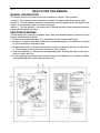
MANUAL ORGANIZATION
This manual consists of chapters for the main categories of subjects. (See “symbols”)
1st title 1: This is the title of the chapter with its symbol in the upper right corner of each page.
2nd title 2: This title indicates the section of the chapter and only appears on the first page of each
section. It is located in the upper left corner of the page.
3rd title 3: This title indicates a sub-section that is followed by step-by-step procedures accompanied by corresponding illustrations.
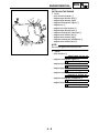
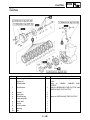
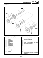
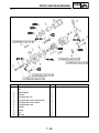
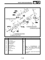
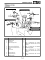
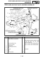
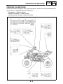
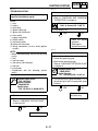
EXPLODED DIAGRAMS
To help identify parts and clarify procedure steps, there are exploded diagrams at the start of each
removal and disassembly section.
1. An easy-to-see exploded diagram 4 is provided for removal and disassembly jobs.
2. Numbers 5 are given in the order of the jobs in the exploded diagram. A number that is enclosed
by a circle indicates a disassembly step.
3. An explanation of jobs and notes is presented in an easy-to-read way by the use of symbol marks
6. The meanings of the symbol marks are given on the next page.
4. A job instruction chart 7 accompanies the exploded diagram, providing the order of jobs, names
of parts, notes in jobs, etc.
5. For jobs requiring more information, the step-by-step format supplements 8 are given in addition
to the exploded diagram and the job instruction chart.
1
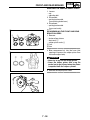
EBS00006
2
GEN
INFO
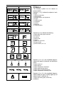
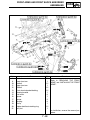
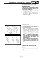
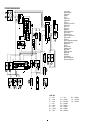
SYMBOLS
The following symbols are not relevant to
every machine.
Symbols 1 to 9 indicate the subject of each
chapter.
SPEC
3
4
CHK
ADJ
1 General information
2 Specifications
3 Periodic checks and adjustments
4 Engine
5 Cooling system
6 Carburetor
7 Chassis
8 Electrical
9 Troubleshooting
ENG
5
6
CARB
COOL
7
8
CHAS
ELEC
9
0
–
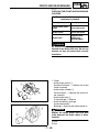
Symbols 0 to G indicate the following
0 Serviceable with engine mounted
A Filling fluid
B Lubricant
C Special tool
D Torque
E Wear limit, clearance
F Engine speed
G Electrical data (Ω, V, A)
TRBL
SHTG
A
B
C
D
+
T.
R.
E
F
G
H
I
J
G
E
K
M
L
B
M
M
LS
N
Symbols H to N in the exploded diagrams
indicate the types of lubricants and lubrication
points.
O
LT
New
H Apply engine oil
I Apply gear oil
J Apply molybdenum disulfide oil
K Apply wheel bearing grease
L Apply lithium-soap-based grease
M Apply molybdenum disulfide grease
Symbols N to O in the exploded diagrams
indicate where to apply a locking agent N and
when to install a new part O.
N Apply the locking agent (LOCTITE®)
O Replace
EBS00008
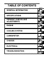
TABLE OF CONTENTS
GENERAL INFORMATION
SPECIFICATIONS
PERIODIC CHECKS AND
ADJUSTMENTS
ENGINE
COOLING SYSTEM
CARBURETOR
CHASSIS
GEN
INFO
1
SPEC
2
CHK
ADJ
3
ENG
4
COOL
5
CARB
6
CHAS
7
–
ELECTRICAL
TROUBLESHOOTING
+
ELEC
8
TRBL
SHTG
9
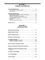
CHAPTER 1
GENERAL INFORMATION
MACHINE IDENTIFICATION...........................................................................1-1
VEHICLE IDENTIFICATION NUMBER .....................................................1-1
MODEL LABEL.......................................................................................... 1-1
IMPORTANT INFORMATION ......................................................................... 1-2
PREPARATION FOR REMOVAL AND DISASSEMBLY........................... 1-2
REPLACEMENT PARTS...........................................................................1-2
GASKETS, OIL SEALS AND O-RINGS .................................................... 1-2
LOCK WASHERS/PLATES AND COTTER PINS ..................................... 1-3
BEARINGS AND OIL SEALS .................................................................... 1-3
CIRCLIPS ..................................................................................................1-3
CHECKING THE CONNECTIONS............................................................ 1-4
SPECIAL TOOLS ............................................................................................ 1-5
CHAPTER 2
SPECIFICATIONS
GENERAL SPECIFICATIONS ........................................................................ 2-1
ENGINE SPECIFICATIONS ............................................................................2-4
CHASSIS SPECIFICATIONS ........................................................................2-12
ELECTRICAL SPECIFICATIONS .................................................................2-14
TIGHTENING TORQUES .............................................................................. 2-16
ENGINE TIGHTENING TORQUES ........................................................ 2-16
CHASSIS TIGHTENING TORQUES ......................................................2-19
HOW TO USE THE CONVERSION TABLE.................................................. 2-21
GENERAL TIGHTENING TORQUE SPECIFICATIONS...............................2-21
LUBRICATION POINTS AND LUBRICANT TYPES .................................... 2-22
ENGINE................................................................................................... 2-22
COOLANT FLOW DIAGRAMS ..................................................................... 2-24
OIL FLOW DIAGRAMS ................................................................................. 2-26
CABLE ROUTING ......................................................................................... 2-28
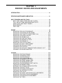
CHAPTER 3
PERIODIC CHECKS AND ADJUSTMENTS
INTRODUCTION.............................................................................................. 3-1
PERIODIC MAINTENANCE/LUBRICATION .................................................. 3-1
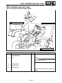
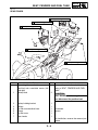
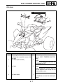
SEAT, FENDERS AND FUEL TANK .............................................................. 3-3
SEAT, FUEL TANK COVER AND SIDE COVERS ...................................3-3
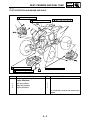
FOOT PROTECTORS AND ENGINE SKID PLATE .................................3-4
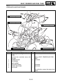
HEADLIGHTS AND FRONT FENDER......................................................3-5
REAR FENDER......................................................................................... 3-6
FUEL TANK............................................................................................... 3-7
ENGINE ...........................................................................................................3-8
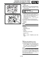
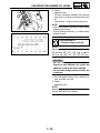
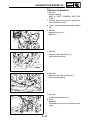
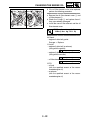
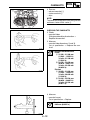
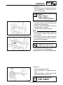
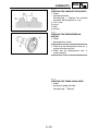
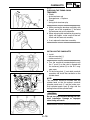
ADJUSTING THE VALVE CLEARANCE .................................................. 3-8
ADJUSTING THE ENGINE IDLING SPEED ...........................................3-13
ADJUSTING THE THROTTLE LEVER FREE PLAY ..............................3-14
ADJUSTING THE SPEED LIMITER........................................................ 3-16
CHECKING THE SPARK PLUG ............................................................. 3-17
CHECKING THE IGNITION TIMING.......................................................3-18
CHECKING THE ENGINE OIL LEVEL....................................................3-19
CHANGING THE ENGINE OIL ...............................................................3-21
ADJUSTING THE CLUTCH CABLE........................................................ 3-24
CLEANING THE AIR FILTER ELEMENT................................................ 3-26
CHECKING THE COOLANT LEVEL.......................................................3-28
CHANGING THE COOLANT................................................................... 3-28
CHECKING THE COOLANT TEMPERATURE WARNING LIGHT.........3-32
CLEANING THE SPARK ARRESTER ....................................................3-33
CHASSIS ....................................................................................................... 3-34
ADJUSTING THE FRONT BRAKE ......................................................... 3-34
ADJUSTING THE BRAKE LEVER .......................................................... 3-34
ADJUSTING THE REAR BRAKE............................................................ 3-34
ADJUSTING THE PARKING BRAKE......................................................3-35
CHECKING THE BRAKE FLUID LEVEL................................................. 3-36
CHECKING THE FRONT BRAKE PADS ................................................ 3-37
CHECKING THE REAR BRAKE PADS .................................................. 3-38
ADJUSTING THE REAR BRAKE LIGHT SWITCH .................................3-39
CHECKING THE BRAKE HOSES........................................................... 3-39
BLEEDING THE HYDRAULIC BRAKE SYSTEM ................................... 3-40
ADJUSTING THE SHIFT PEDAL............................................................ 3-42
ADJUSTING THE DRIVE CHAIN SLACK ............................................... 3-43
CHECKING THE STEERING SYSTEM .................................................. 3-44
ADJUSTING THE TOE-IN....................................................................... 3-45
CHECKING THE FRONT AND REAR SHOCK ABSORBERS ............... 3-46
ADJUSTING THE FRONT SHOCK ABSORBERS .................................3-47
ADJUSTING THE REAR SHOCK ABSORBER ...................................... 3-49
CHECKING THE TIRES..........................................................................3-53
CHECKING THE WHEELS ..................................................................... 3-55
CHECKING AND LUBRICATING THE CABLES .................................... 3-55
LUBRICATING THE LEVERS AND PEDALS .........................................3-56
ELECTRICAL SYSTEM................................................................................. 3-57
CHECKING AND CHARGING THE BATTERY....................................... 3-57
CHECKING THE FUSES ........................................................................3-64
ADJUSTING THE HEADLIGHT BEAM ...................................................3-65
REPLACING A HEADLIGHT BULB ........................................................ 3-66
CHAPTER 4
ENGINE
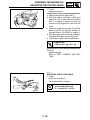
ENGINE REMOVAL ........................................................................................4-1
MUFFLER AND EXHAUST PIPE.............................................................. 4-1
INSTALLING THE EXHAUST PIPE AND MUFFLER................................4-2
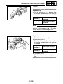
LEADS, CABLES AND HOSES ................................................................4-4
ENGINE MOUNTING BOLTS ...................................................................4-6
INSTALLING THE ENGINE....................................................................... 4-8
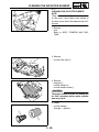
CAMSHAFTS...................................................................................................4-9
CYLINDER HEAD COVER........................................................................ 4-9
CAMSHAFTS .......................................................................................... 4-10
REMOVING THE CAMSHAFTS..............................................................4-11
CHECKING THE CAMSHAFTS ..............................................................4-12
CHECKING THE CAMSHAFT SPROCKETS .........................................4-14
CHECKING THE DECOMPRESSION SYSTEM..................................... 4-14
CHECKING THE TIMING CHAIN GUIDE ............................................... 4-14
CHECKING THE TIMING CHAIN TENSIONER...................................... 4-15
INSTALLING THE CAMSHAFTS ............................................................ 4-15
CYLINDER HEAD.......................................................................................... 4-18
REMOVING THE CYLINDER HEAD.......................................................4-20
CHECKING THE CYLINDER HEAD .......................................................4-20
CHECKING THE OIL DELIVERY PIPE...................................................4-21
CHECKING THE TIMING CHAIN GUIDE ............................................... 4-21
INSTALLING THE CYLINDER HEAD .....................................................4-21
VALVES AND VALVE SPRINGS.................................................................. 4-24
REMOVING THE VALVES AND VALVE SPRINGS ...............................4-26
CHECKING THE VALVES AND VALVE SPRINGS ................................4-27
CHECKING THE VALVE LIFTERS ......................................................... 4-32
INSTALLING THE VALVES AND VALVE SPRINGS ..............................4-32
CYLINDER AND PISTON.............................................................................. 4-34
REMOVING THE PISTON ...................................................................... 4-35
CHECKING THE CYLINDER AND PISTON ...........................................4-35
CHECKING THE PISTON RINGS........................................................... 4-37
CHECKING THE PISTON PIN ................................................................4-38
INSTALLING THE PISTON ..................................................................... 4-40
INSTALLING THE CYLINDER ................................................................4-41
A.C. MAGNETO............................................................................................. 4-42
REMOVING THE A.C. MAGNETO ROTOR............................................4-44
CHECKING THE STATOR COIL AND PICKUP COIL ............................ 4-44
CHECKING THE STARTER CLUTCH ....................................................4-45
CHECKING THE TORQUE LIMITER......................................................4-46
INSTALLING THE A.C. MAGNETO ROTOR ..........................................4-46
CLUTCH ........................................................................................................4-48
REMOVING THE CLUTCH ..................................................................... 4-50
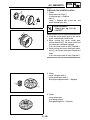
CHECKING THE FRICTION PLATES.....................................................4-50
CHECKING THE CLUTCH PLATES .......................................................4-51
CHECKING THE CLUTCH SPRINGS.....................................................4-51
CHECKING THE CLUTCH HOUSING ....................................................4-51
CHECKING THE CLUTCH BOSS........................................................... 4-52
CHECKING THE PRESSURE PLATE ....................................................4-52
CHECKING THE PUSH RODS ...............................................................4-52
CHECKING THE PUSH LEVER..............................................................4-52
CHECKING THE PRIMARY DRIVEN GEAR ..........................................4-52
INSTALLING THE CLUTCH.................................................................... 4-53
BALANCER ................................................................................................... 4-55
REMOVING THE BALANCER DRIVE GEAR
AND BALANCER DRIVEN GEAR .......................................................... 4-56
CHECKING THE PRIMARY DRIVE GEAR, BALANCER DRIVE GEAR
AND BALANCER DRIVEN GEAR .......................................................... 4-56
CHECKING THE BALANCER .................................................................4-56
INSTALLING THE BALANCER DRIVE GEAR
AND BALANCER DRIVEN GEAR .......................................................... 4-57
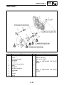
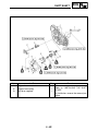
OIL PUMP...................................................................................................... 4-58
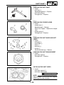
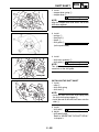
CHECKING THE OIL PUMP ................................................................... 4-60
SHIFT SHAFT................................................................................................4-61
CHECKING THE SHIFT SHAFT ............................................................. 4-63
CHECKING THE STOPPER LEVER ......................................................4-63
CHECKING THE SHIFT GUIDE AND SHIFT LEVER............................. 4-63
CHECKING THE SHIFT DRUM SEGMENT ...........................................4-63
INSTALLING THE SHIFT LEVER ........................................................... 4-63
INSTALLING THE SHIFT SHAFT ........................................................... 4-64
CRANKCASE ................................................................................................4-65
OIL SEAL AND BEARING....................................................................... 4-67
SEPARATING THE CRANKCASE.......................................................... 4-68
CHECKING THE OIL STRAINER AND OIL DELIVERY PIPE 2 ............. 4-68
CHECKING THE TIMING CHAIN AND GUIDE....................................... 4-69
CHECKING THE BEARINGS AND OIL SEALS...................................... 4-69
CHECKING THE CRANKCASE ..............................................................4-69
ASSEMBLING THE CRANKCASE.......................................................... 4-70
CRANKSHAFT ..............................................................................................4-72
REMOVING THE CRANKSHAFT ........................................................... 4-73
CHECKING THE CRANKSHAFT ............................................................ 4-73
INSTALLING THE CRANKSHAFT .......................................................... 4-74
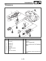
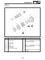
TRANSMISSION............................................................................................ 4-75
MAIN AXLE ............................................................................................. 4-76
DRIVE AXLE ........................................................................................... 4-77
CHECKING THE SHIFT FORKS............................................................. 4-78
CHECKING THE SHIFT DRUM ..............................................................4-78
CHECKING THE TRANSMISSION ......................................................... 4-78
ASSEMBLING THE MAIN AXLE AND DRIVE AXLE ..............................4-79
INSTALLING THE TRANSMISSION .......................................................4-80
CHAPTER 5
COOLING SYSTEM
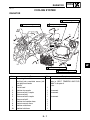
RADIATOR ...................................................................................................... 5-1
CHECKING THE RADIATOR.................................................................... 5-3
INSTALLING THE RADIATOR..................................................................5-4
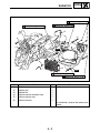
WATER PUMP.................................................................................................5-5
CHECKING THE WATER PUMP .............................................................. 5-7
CHAPTER 6
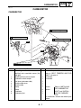
CARBURETOR
CARBURETOR................................................................................................6-1
DISASSEMBLING THE CARBURETOR................................................... 6-5
CHECKING THE CARBURETOR ............................................................. 6-5
ASSEMBLING THE CARBURETOR.........................................................6-7
ADJUSTING THE ACCELERATOR PUMP TIMING .................................6-8
INSTALLING THE CARBURETOR JOINT................................................ 6-8
INSTALLING THE CARBURETOR ........................................................... 6-9
CHECKING AND ADJUSTING THE THROTTLE POSITION SENSOR ...6-9
CHAPTER 7
CHASSIS
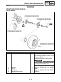
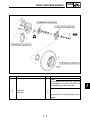
FRONT AND REAR WHEELS ........................................................................ 7-1
FRONT WHEELS ......................................................................................7-1
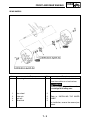
REAR WHEELS ........................................................................................7-3
CHECKING THE WHEELS ....................................................................... 7-4
CHECKING THE WHEEL HUBS............................................................... 7-4
CHECKING THE BRAKE DISCS .............................................................. 7-5
INSTALLING THE FRONT WHEEL HUB BEARINGS .............................. 7-6
INSTALLING THE FRONT BRAKE DISCS............................................... 7-6
INSTALLING THE FRONT WHEELS........................................................7-6
INSTALLING THE WHEEL HUBS............................................................. 7-7
REAR AXLE AND REAR AXLE HUB ............................................................. 7-8
REMOVING THE REAR AXLE................................................................7-10
CHECKING THE REAR AXLE ................................................................7-11
CHECKING THE DRIVEN SPROCKET .................................................. 7-11
CHECKING THE BRAKE DISC...............................................................7-11
INSTALLING THE DRIVEN SPROCKET ................................................ 7-12
INSTALLING THE REAR AXLE ..............................................................7-12
FRONT AND REAR BRAKES....................................................................... 7-13
FRONT BRAKE PADS ............................................................................7-13
REAR BRAKE PADS............................................................................... 7-14
REPLACING THE FRONT BRAKE PADS .............................................. 7-15
REPLACING THE REAR BRAKE PADS................................................. 7-17
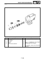
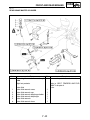
FRONT BRAKE MASTER CYLINDER....................................................7-19
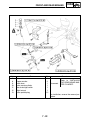
REAR BRAKE MASTER CYLINDER ......................................................7-21
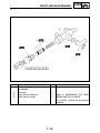
CHECKING THE MASTER CYLINDERS................................................ 7-24
ASSEMBLING THE FRONT BRAKE MASTER CYLINDER ................... 7-25
ASSEMBLING THE REAR BRAKE MASTER CYLINDER......................7-25
INSTALLING THE FRONT BRAKE MASTER CYLINDER......................7-26
INSTALLING THE REAR BRAKE MASTER CYLINDER ........................ 7-27
FRONT BRAKE CALIPERS .................................................................... 7-29
REAR BRAKE CALIPER .........................................................................7-31
REMOVING THE PARKING BRAKE CABLE..........................................7-34
DISASSEMBLING THE FRONT AND REAR BRAKE CALIPERS ..........7-34
CHECKING THE FRONT AND REAR BRAKE CALIPERS ....................7-35
ASSEMBLING THE FRONT BRAKE CALIPERS.................................... 7-36
ASSEMBLING THE REAR BRAKE CALIPER ........................................ 7-36
INSTALLING THE FRONT BRAKE CALIPERS ...................................... 7-38
INSTALLING THE REAR BRAKE CALIPER...........................................7-39
STEERING SYSTEM .....................................................................................7-41
HANDLEBAR........................................................................................... 7-41
REMOVING THE FRONT BRAKE LIGHT SWITCH
AND CLUTCH SWITCH .........................................................................7-43
REMOVING THE HANDLEBAR GRIPS.................................................. 7-43
CHECKING THE HANDLEBAR ..............................................................7-43
INSTALLING THE HANDLEBAR ............................................................ 7-44
INSTALLING THE HANDLEBAR GRIPS ................................................ 7-44
INSTALLING THE CLUTCH LEVER .......................................................7-45
INSTALLING THE BRAKE MASTER CYLINDER ................................... 7-45
STEERING STEM ...................................................................................7-46
REMOVING THE BEARING RETAINER ................................................ 7-48
CHECKING THE STEERING STEM .......................................................7-48
INSTALLING THE BEARING RETAINER ............................................... 7-48
INSTALLING THE STEERING STEM .....................................................7-48
INSTALLING THE LOCK WASHER........................................................ 7-49
INSTALLING THE PITMAN ARM............................................................ 7-49
TIE-RODS AND STEERING KNUCKLES ............................................... 7-50
REMOVING THE STEERING KNUCKLES ............................................. 7-51
CHECKING THE TIE-RODS ................................................................... 7-51
CHECKING THE STEERING KNUCKLES.............................................. 7-51
INSTALLING THE TIE-RODS .................................................................7-51
FRONT ARMS AND FRONT SHOCK ABSORBER ASSEMBLIES ............. 7-52
REMOVING THE FRONT ARMS ............................................................ 7-54
CHECKING THE FRONT ARMS............................................................. 7-54
HANDLING THE FRONT SHOCK ABSORBER
AND GAS CYLINDER ............................................................................7-54
DISPOSING OF A FRONT SHOCK ABSORBER
AND GAS CYLINDER ............................................................................7-55
CHECKING THE FRONT SHOCK ABSORBERS................................... 7-55
CHECKING THE BALL JOINTS..............................................................7-56
INSTALLING THE FRONT ARMS........................................................... 7-57
REAR SHOCK ABSORBER AND RELAY ARM ..........................................7-58
HANDLING THE REAR SHOCK ABSORBER
AND GAS CYLINDER ............................................................................7-60
DISPOSING OF A REAR SHOCK ABSORBER
AND GAS CYLINDER ............................................................................7-60
REMOVING THE REAR SHOCK ABSORBER ....................................... 7-61
CHECKING THE REAR SHOCK ABSORBER........................................ 7-61
CHECKING THE RELAY ARM AND CONNECTING ARM.....................7-61
INSTALLING THE RELAY ARM AND CONNECTING ARM................... 7-62
INSTALLING THE REAR SHOCK ABSORBER...................................... 7-62
SWINGARM AND DRIVE CHAIN.................................................................. 7-63
REMOVING THE SWINGARM................................................................7-65
CHECKING THE SWINGARM ................................................................7-65
CHECKING THE DRIVE CHAIN ............................................................. 7-67
INSTALLING THE SWINGARM ..............................................................7-68
INSTALLING THE DRIVE SPROCKET...................................................7-69
CHAPTER 8
ELECTRICAL
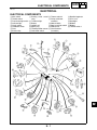
ELECTRICAL COMPONENTS........................................................................ 8-1
CHECKING SWITCH CONTINUITY................................................................8-2
CHECKING THE SWITCHES..........................................................................8-4
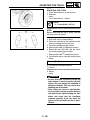
CHECKING THE BULBS AND BULB SOCKETS .......................................... 8-6
TYPES OF BULBS .................................................................................... 8-6
CHECKING THE CONDITION OF THE BULBS ....................................... 8-6
CHECKING THE CONDITION OF THE BULB SOCKETS .......................8-8
IGNITION SYSTEM ......................................................................................... 8-9
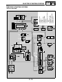
CIRCUIT DIAGRAM .................................................................................. 8-9
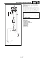
THROTTLE OVERRIDE SYSTEM (T.O.R.S.) OPERATION .................. 8-10
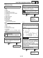
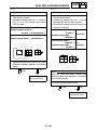
TROUBLESHOOTING ............................................................................8-11
CHECKING THE THROTTLE OVERRIDE SYSTEM..............................8-14
ELECTRIC STARTING SYSTEM .................................................................. 8-16
CIRCUIT DIAGRAM ................................................................................ 8-16
STARTING CIRCUIT CUT-OFF SYSTEM OPERATION ........................ 8-17
TROUBLESHOOTING ............................................................................8-18
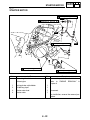
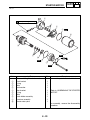
STARTER MOTOR........................................................................................ 8-22
CHECKING THE STARTER MOTOR .....................................................8-24
ASSEMBLING THE STARTER MOTOR................................................. 8-25
CHARGING SYSTEM....................................................................................8-26
CIRCUIT DIAGRAM ................................................................................ 8-26
TROUBLESHOOTING ............................................................................8-27
LIGHTING SYSTEM ......................................................................................8-29
CIRCUIT DIAGRAM ................................................................................ 8-29
TROUBLESHOOTING ............................................................................8-30
CHECKING THE LIGHTING SYSTEM....................................................8-31
SIGNAL SYSTEM.......................................................................................... 8-33
CIRCUIT DIAGRAM ................................................................................ 8-33
TROUBLESHOOTING ............................................................................8-34
CHECKING THE SIGNALING SYSTEM ................................................. 8-35
COOLING SYSTEM....................................................................................... 8-39
CIRCUIT DIAGRAM ................................................................................ 8-39
TROUBLESHOOTING ............................................................................8-40
CHAPTER 9
TROUBLESHOOTING
STARTING FAILURE/HARD STARTING .......................................................9-1
FUEL SYSTEM.......................................................................................... 9-1
ELECTRICAL SYSTEM.............................................................................9-1
COMPRESSION SYSTEM........................................................................ 9-2
POOR IDLE SPEED PERFORMANCE ........................................................... 9-2
POOR IDLE SPEED PERFORMANCE.....................................................9-2
POOR MEDIUM AND HIGH-SPEED PERFORMANCE..................................9-2
POOR MEDIUM AND HIGH-SPEED PERFORMANCE ........................... 9-2
FAULTY GEAR SHIFTING..............................................................................9-3
HARD SHIFTING.......................................................................................9-3
SHIFT PEDAL DOES NOT MOVE ............................................................ 9-3
JUMPS OUT GEAR................................................................................... 9-3
CLUTCH SLIPPING/DRAGGING.................................................................... 9-3
CLUTCH SLIPPING .................................................................................. 9-3
CLUTCH DRAGGING ............................................................................... 9-3
OVERHEATING............................................................................................... 9-4
OVERHEATING ........................................................................................9-4
FAULTY BRAKE ............................................................................................. 9-4
POOR BRAKING EFFECT........................................................................ 9-4
SHOCK ABSORBER MALFUNCTION ........................................................... 9-4
MALFUNCTION......................................................................................... 9-4
UNSTABLE HANDLING.................................................................................. 9-5
UNSTABLE HANDLING ............................................................................9-5
LIGHTING SYSTEM ........................................................................................9-5
HEADLIGHT DOES NOT COME ON ........................................................9-5
TAIL/BRAKE LIGHT DOES NOT LIGHT................................................... 9-5
BULB BURNT OUT ................................................................................... 9-5
TAIL/BRAKE LIGHT BULB BURNT OUT.................................................. 9-5
MACHINE IDENTIFICATION
GEN
INFO
EBS00009
GENERAL INFORMATION
MACHINE IDENTIFICATION
EBS00010
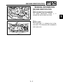
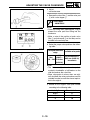
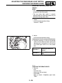
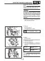
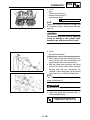
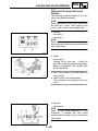
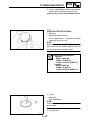
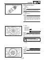
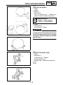
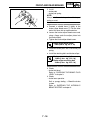
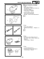
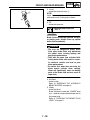
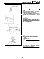
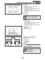
VEHICLE IDENTIFICATION NUMBER
The vehicle identification number 1
stamped into the left side of the frame.
is
1
EBS00011
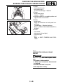
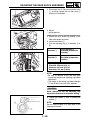
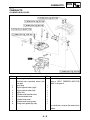
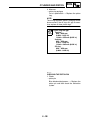
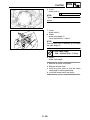
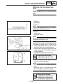
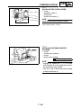
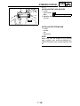
MODEL LABEL
The model label 1 is affixed to the air filter
case cover. This information will be needed to
order spare parts.
1
1-1
1
IMPORTANT INFORMATION
GEN
INFO
EBS00013
IMPORTANT INFORMATION
PREPARATION FOR REMOVAL AND
DISASSEMBLY
1. Before removal and disassembly remove all
dirt, mud, dust and foreign material.
2. Use only the proper tools and cleaning
equipment.
Refer to “SPECIAL TOOLS”.
3. When disassembling always keep mated
parts together. This includes gears, cylinders, pistons and other parts that have been
“mated” through normal wear. Mated parts
must always be reused or replaced as an
assembly.
4. During disassembly, clean all of the parts
and place them in trays in the order of disassembly. This will speed up assembly and
allow for the correct installation of all parts.
5. Keep all parts away from any source of fire.
EBS00014
REPLACEMENT PARTS
1. Use only genuine Yamaha parts for all
replacements. Use oil and grease recommended by Yamaha for all lubrication jobs.
Other brands may be similar in function and
appearance, but inferior in quality.
EBS00015
GASKETS, OIL SEALS AND O-RINGS
1. When overhauling the engine, replace all
gaskets, seals and O-rings. All gasket surfaces, oil seal lips and O-rings must be
cleaned.
2. During reassembly properly oil all mating
parts and bearings, and lubricate the oil
seal lips with grease.
1-2
IMPORTANT INFORMATION
GEN
INFO
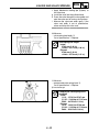
EBS00016
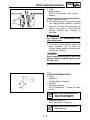
LOCK WASHERS/PLATES AND COTTER
PINS
After removal, replace all lock washers/plates
1 and cotter pins. After the bolt or nut has
been tightened to specification, bend the lock
tabs along a flat of the bolt or nut.
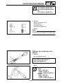
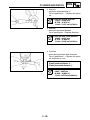
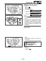
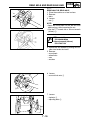
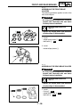
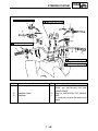
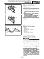
EBS00017
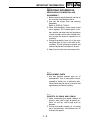
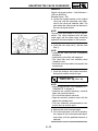
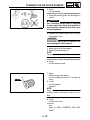
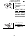
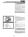
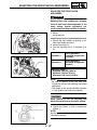
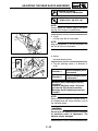
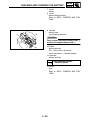
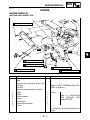
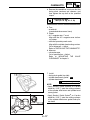
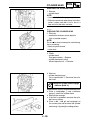
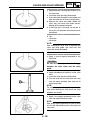
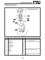
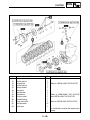
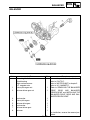
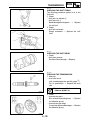
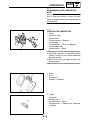
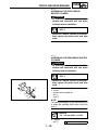
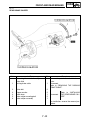
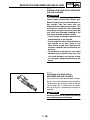
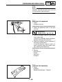
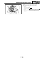
BEARINGS AND OIL SEALS
Install bearings and oil seals so that the manufacturer’s marks or numbers are visible. When
installing oil seals, lubricate the oil seal lips
with a light coat of lithium-soap-based grease.
Oil bearings liberally when installing, if appropriate.
1 Oil seal
CAUTION:
_
Do not spin the bearing with compressed
air because this will damage the bearing
surfaces.
1 Bearing
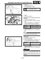
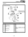
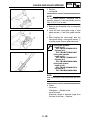
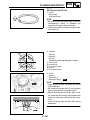
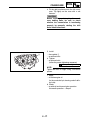
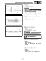
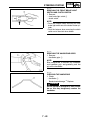
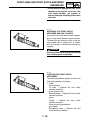
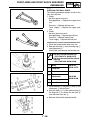
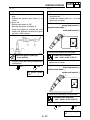
EBS00018
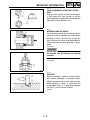
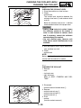
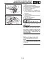
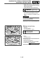
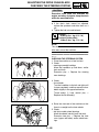
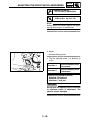
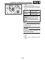
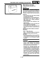
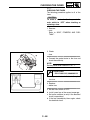
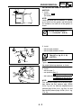
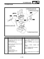
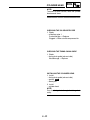
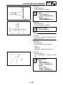
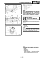
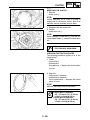
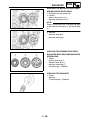
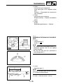
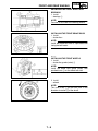
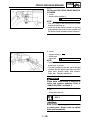
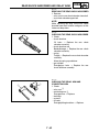
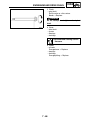
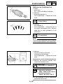
CIRCLIPS
Before reassembly, check all circlips carefully
and replace damaged or distorted circlips.
Always replace piston pin clips after one use.
When installing a circlip 1, make sure the
sharp-edged corner 2 is positioned opposite
the thrust 3 that the circlip receives.
4 Shaft
1-3
IMPORTANT INFORMATION
GEN
INFO
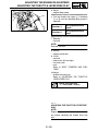
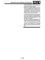
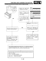
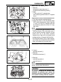
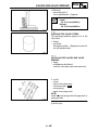
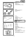
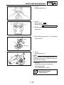
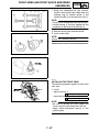
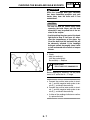
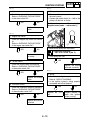
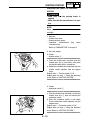
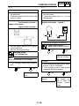
EBS00019
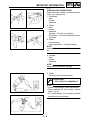
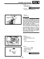
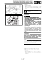
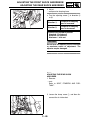
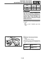
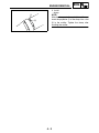
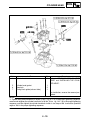
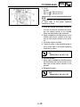
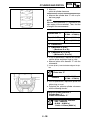
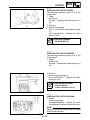
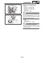
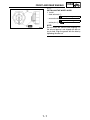
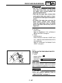
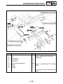
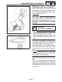
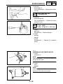
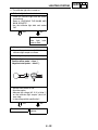
CHECKING THE CONNECTIONS
Check the leads, couplers, and connectors for
stains, rust, moisture, etc.
1. Disconnect:
• lead
• coupler
• connector
2. Check:
• lead
• coupler
• connector
Moisture → Dry with an air blower.
Rust/stains → Connect and disconnect several times.
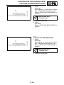
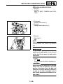
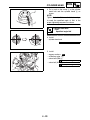
3. Check:
• all connections
Loose connection → Connect properly.
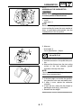
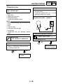
NOTE:
If the pin 1 on the terminal is flattened, bend it
up.
_
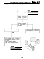
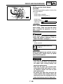
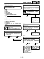
4.
•
•
•
Connect:
lead
coupler
connector
NOTE:
Make sure all connections are tight.
_
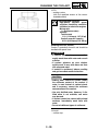
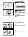
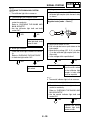
5. Check:
• continuity (with the pocket tester)
Pocket tester
P/N. YU-03112-C, 90890-03112
NOTE:
• If there is no continuity, clean the terminals.
• When checking the wire harness, perform
steps (1) to (3).
• As a quick remedy, use a contact revitalizer
available at most part stores.
_
1-4
SPECIAL TOOLS
GEN
INFO
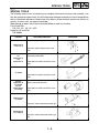
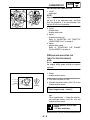
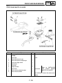
EBS00021
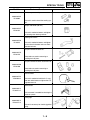
SPECIAL TOOLS
The following special tools are necessary for complete and accurate tune-up and assembly. Use
only the appropriate special tools; this will help prevent damage caused by the use of inappropriate
tools or improvised techniques. Special tools may differ by shape and part number from country to
country. In such a case, two types are provided.
When placing an order, refer to the list provided below to avoid any mistakes.
For US and CDN
P/N. YM-, YU-, YS-, YK-, ACCExcept for US and CDN
P/N. 90890Tool No.
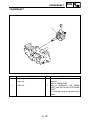
Tool name/Function
Crankcase separating tool
90890-01135
YU-01135-A
This tool is used to separate the crankcase.
Pot
90890-01274
Bolt
90890-01275
Crankshaft installer pot
Crankshaft installer bolt
These tools are used to install the crankshaft.
Crankshaft installer set
YU-90050
These tools are used to install the crankshaft.
Adapter
90890-01278
YM-90063
Spacer
90890-04081
YM-91044
Adapter
Spacer (crankshaft installer)
These tools are used to install the crankshaft.
Piston pin puller
90890-01304
YU-01304
This tool is used to remove the piston pin.
Radiator cap tester
90890-01325
YU-24460-01
This tool is used to check the cooling system.
1-5
Illustration
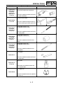
SPECIAL TOOLS
Tool No.
Tool name/Function
Radiator cap tester adapter
90890-01352
YU-33984
This tool is used to check the cooling system.
Damper rod holder (30 mm)
90890-01327
YM-01327
This tool is needed to loosen and tighten
the steering stem bearing retainer.
Steering nut wrench
90890-01443
YU-33975
This tool is needed to loosen and tighten
the front shock absorber and rear shock
absorber locknuts.
Ball joint remover/installer set
90890-01474
YM-01474
These tools are used to removing or
installing the ball joints.
Ball joint remover/installer attachment set
90890-01480
YM-01480
These tools are used to removing or
installing the ball joints.
Sheave holder
90890-01701
YS-01880-A
This tool is needed to hold the A.C. magneto rotor when loosen or tighten the A.C.
magneto rotor nut.
Pocket tester
90890-03112
YU-03112-C
This instrument is needed for checking the
electrical system.
Timing light
90890-03141
YM-33277-A
This tool is necessary for checking ignition
timing.
1-6
GEN
INFO
Illustration
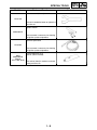
SPECIAL TOOLS
Tool No.
Compressor
90890-04019
YM-04019
Attachment
90890-04114
YM-04114
Tool name/Function
Valve spring compressor
Valve spring compressor attachment
This tool is needed to remove and install
the valve assemblies.
Universal clutch holder
90890-04086
YM-91042
90890-04097
YM-04097
90890-04116
YM-04116
90890-04098
YM-04098
90890-04117
YM-04117
90890-04099
YM-04099
90890-04118
YM-04118
This tool is needed to hold the clutch carrier when removing or installing the carrier
nut.
Valve guide remover (ø 5)
Valve guide remover (ø 4.5)
This tool is needed to remove and install
the valve guides.
Valve guide installer (ø 5)
Valve guide installer (ø 4.5)
This tool is needed to install the valve
guides.
Valve guide reamer (ø 5)
Valve guide reamer (ø 4.5)
This tool is needed to rebore the new
valve guides.
Valve lapper
90890-04101
This tool is needed to remove and install
the valve lifters.
Rotor puller
90890-04142
YM-04142
These tools are needed to remove the
A.C. magneto rotor.
PTT wrench 46
90890-06588
This tool is needed to loosen or tighten the
rear axle nut.
1-7
GEN
INFO
Illustration
SPECIAL TOOLS
Tool No.
Tool name/Function
Axle nut wrench (46 mm)
YM-37134
This tool is needed to loosen or tighten the
rear axle nut.
Ignition checker
90890-06754
This instrument is necessary for checking
the ignition system components.
Dynamic spark tester
YM-34487
This instrument is necessary for checking
the ignition system components.
Bond
90890-85505
Sealant
ACC-11001-05-01
Yamaha bond No. 1215
Sealant (Quick Gasket®)
This sealant (bond) is used on crankcase
mating surfaces, etc.
1-8
GEN
INFO
Illustration
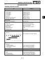
GENERAL SPECIFICATIONS
SPEC
EBS01001
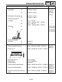
SPECIFICATIONS
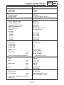
GENERAL SPECIFICATIONS
Item
Standard
Model code
Dimensions
Overall length
Overall width
Overall height
Seat height
Wheelbase
Minimum ground clearance
Minimum turning radius
Basic weight
With oil and full fuel tank
Engine
Engine type
Cylinder arrangement
Displacement
Bore × stroke
Compression ratio
Starting system
Lubrication system
Oil type or grade
Engine oil
5TG1
1,840 mm (72.4 in)
1,170 mm (46.1 in)
1,090 mm (42.9 in)
800 mm (31.5 in)
1,280 mm (50.4 in)
255 mm (10.04 in)
3,500 mm (137.8 in)
169 kg (373 lb)
Liquid-cooled 4-stroke, DOHC
Forward-inclined single cylinder
439 cm3 (26.79 cu in)
95.0 × 62.0 mm (3.74 × 2.44 in)
11.9:1
Electric starter
Dry sump
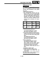
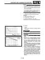
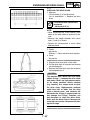
API service SE, SF, SG type or higher
0°
10°
30°
50°
70°
90°
110°
130°F
YAMALUBE4 (20W40) or SAE 20W40
YAMALUBE4 (10W30) or SAE 10W30
SAE 5W30
-20°
-10°
0°
10°
20°
30°
40°
50°C
Oil capacity
Engine oil
Periodic oil change
With oil filter replacement
Total amount
Radiator capacity (including all routes)
Air filter
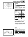
Fuel
Type
Fuel tank capacity
Fuel reserve amount
1.75 L (1.54 Imp qt, 1.85 US qt)
1.85 L (1.63 Imp qt, 1.96 US qt)
1.95 L (1.72 Imp qt, 2.06 US qt)
1.3 L (1.14 Imp qt, 1.37 US qt)
Wet type element
Premium unleaded gasoline only
10.0 L (2.20 Imp gal, 2.64 US gal)
1.9 L (0.42 Imp gal, 0.50 US gal)
2-1
2
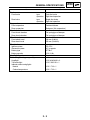
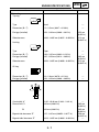
GENERAL SPECIFICATIONS
Item
Carburetor
Type/quantity
Manufacturer
Spark plug
Type/manufacturer
Spark plug gap
Clutch type
Transmission
Primary reduction system
Primary reduction ratio
Secondary reduction system
Secondary reduction ratio
Transmission type
Operation
Gear ratio
1st gear
2nd gear
3rd gear
4th gear
5th gear
Chassis
Frame type
Caster angle
Camber angle
Kingpin angle
Kingpin offset
Trail
Tread (STD)
front
rear
Toe-in (with tires touching the ground)
Tire
Type
Size
front
rear
Manufacturer
front
rear
Type
front
rear
Tire pressure (cold tire)
Maximum load*
Off-road riding
front
rear
*Load in total weight of cargo, rider and
accessories
SPEC
Standard
5TG1 00 × 1
KEIHIN
CR8E/NGK
0.7 ~ 0.8 mm (0.028 ~ 0.031 in)
Wet, multiple disc
Spur gear
62/22 (2.818)
Chain drive
38/14 (2.714)
Constant mesh, 5-speed
Left foot operation
29/12 (2.416)
27/14 (1.928)
25/16 (1.562)
23/18 (1.277)
21/20 (1.050)
Steel tube frame
5°
–1.5°
15.4°
1.0 mm (0.04 in)
21.0 mm (0.83 in)
950 mm (37.40 in)
900 mm (35.43 in)
2 ~ 12 mm (0.08 ~ 0.47 in)
Tubeless
AT21 × 7-10
AT20 × 10-9
DUNLOP
DUNLOP
KT331A Radial
KT355 Radial
100 kg (220 lb)
30 kPa (0.30 kg/cm2, 4.4 psi)
35 kPa (0.35 kg/cm2, 5.0 psi)
2-2
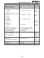
GENERAL SPECIFICATIONS
Item
Brake
Front brake
Rear brake
Suspension
Front suspension
Rear suspension
Shock absorber
Front shock absorber
Rear shock absorber
Wheel travel
Front wheel travel
Rear wheel travel
Electrical
Ignition system
Generator system
Battery type
Battery capacity
Headlight type
Bulb voltage/wattage × quantity
Headlight
Tail/brake light
Indicator and warning lights
Neutral
Coolant temperature
SPEC
Standard
type
operation
type
operation
Dual disc brake
Right hand operation
Single disc brake
Right foot operation
Double wishbone
Swingarm (link suspension)
Coil spring/gas-oil damper
Coil spring/gas-oil damper
230 mm (9.06 in)
256 mm (10.08 in)
DC-C.D.I.
A.C. magneto
GT7B-4
12 V 12 Ah
Krypton bulb
12 V 30 W/30 W × 2
12 V 5 W/21 W × 1
12 V 1.7 W × 1
12 V 1.7 W × 1
2-3
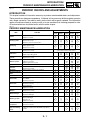
ENGINE SPECIFICATIONS
SPEC
EBS01002
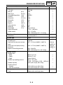
ENGINE SPECIFICATIONS
Item
Standard
Cylinder head
Warp limit
----
Cylinder
Bore size
Camshaft
Drive method
Camshaft cap inside diameter
Camshaft journal diameter
Camshaft-journal-to-camshaft-cap
clearance
Camshaft lobe dimensions
Limit
0.05 mm
(0.002 in)
95.00 ~ 95.01 mm (3.7402 ~ 3.7406 in)
----
Chain drive (Left)
22.000 ~ 22.021 mm (0.8661 ~ 0.8670 in)
---21.967 ~ 21.980 mm (0.8648 ~ 0.8654 in)
---0.020 ~ 0.054 mm (0.0008 ~ 0.0021 in)
0.080 mm
(0.0032 in)
A
B
Intake
“A”
“B”
Exhaust
“A”
“B”
Camshaft runout limit
Timing chain
Timing chain type/No. of links
Timing chain adjustment method
31.200 ~ 31.300 mm (1.2283 ~ 1.2323 in) 31.100 mm
(1.2244 in)
22.550 ~ 22.650 mm (0.8878 ~ 0.8917 in) 22.450 mm
(0.8839 in)
30.950 ~ 31.050 mm (1.2185 ~ 1.2224 in) 30.850 mm
(1.2146 in)
22.494 ~ 22.594 mm (0.8856 ~ 0.8895 in) 22.394 mm
(0.8817 in)
---0.03 mm
(0.0012 in)
98XRH2010-118M
Automatic
2-4
-------
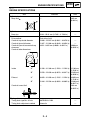
ENGINE SPECIFICATIONS
Item
SPEC
Standard
Valve, valve seat, valve guide
Valve clearance (cold)
IN
EX
Valve dimensions
Limit
0.10 ~ 0.15 mm (0.0039 ~ 0.0059 in)
0.20 ~ 0.25 mm (0.0079 ~ 0.0098 in)
B
-------
C
D
A
Head Diameter
“A” head diameter
“B” face width
“C” seat width
“D” margin thickness
Stem outside diameter
Guide inside diameter
Face Width
Margin Thickness
IN
EX
IN
EX
IN
26.9 ~ 27.1 mm (1.0591 ~ 1.0669 in)
27.9 ~ 28.1 mm (1.0984 ~ 1.1063 in)
2.26 mm (0.0890 in)
2.26 mm (0.0890 in)
0.9 ~ 1.1 mm (0.0354 ~ 0.0433 in)
EX
0.9 ~ 1.1 mm (0.0354 ~ 0.0433 in)
IN
1.0 mm (0.0394 in)
EX
1.0 mm (0.0394 in)
IN
4.475 ~ 4.490 mm (0.1762 ~ 0.1768 in)
EX
4.965 ~ 4.980 mm (0.1955 ~ 0.1961 in)
IN
4.500 ~ 4.512 mm (0.1772 ~ 0.1776 in)
EX
5.000 ~ 5.012 mm (0.1969 ~ 0.1973 in)
Stem-to-guide clearance IN
EX
Valve stem runout
Valve seat width
Seat Width
0.010 ~ 0.037 mm (0.0004 ~ 0.0015 in)
0.020 ~ 0.047 mm (0.0008 ~ 0.0019 in)
----
IN
0.9 ~ 1.1 mm (0.0354 ~ 0.0433 in)
EX
0.9 ~ 1.1 mm (0.0354 ~ 0.0433 in)
2-5
------------1.6 mm
(0.06 in)
1.6 mm
(0.06 in)
0.85 mm
(0.033 in)
0.85 mm
(0.033 in)
4.445 mm
(0.175 in)
4.935 mm
(0.194 in)
4.550 mm
(0.179 in)
5.050 mm
(0.199 in)
0.080 mm
(0.003 in)
0.100 mm
(0.004 in)
0.01 mm
(0.0004 in)
1.6 mm
(0.06 in)
1.6 mm
(0.06 in)
ENGINE SPECIFICATIONS
Item
Valve spring
Free length
Standard
IN
37.03 mm (1.46 in)
EX
37.68 mm (1.48 in)
Set length (valve closed) IN
EX
Compressed pressure
(installed)
IN
27.87 mm (1.10 in)
27.38 mm (1.08 in)
IN
111.3 ~ 127.9 N
(11.35 ~ 13.04 kg, 25.02 ~ 28.75 lb)
127.4 ~ 146.4 N
(12.99 ~ 14.93 kg, 28.64 ~ 32.91 lb)
----
EX
----
IN
EX
Clockwise
Clockwise
EX
Tilt limit
Direction of winding
(top view)
SPEC
Piston
Piston to cylinder clearance
Limit
35.17 mm
(1.38 in)
35.79 mm
(1.41 in)
------------2.5°/1.61 mm
(2.5°/0.063 in)
2.5°/1.65 mm
(2.5°/0.065 in)
-------
0.040 ~ 0.065 mm (0.0016 ~ 0.0026 in)
0.10 mm
(0.004 in)
94.945 ~ 94.960 mm (3.7380 ~ 3.7386 in)
----
Piston size “D”
H
D
Measuring point “H”
Piston off set
Offset direction
Piston pin bore inside diameter
Piston pin outside diameter
Piston-pin-to-piston-pin-bore clearance
10 mm (0.39 in)
---1.0 mm (0.0394 in)
---Intake side
---20.004 ~ 20.015 mm (0.7876 ~ 0.7880 in) 20.045 mm
(0.789 in)
19.991 ~ 20.000 mm (0.7870 ~ 0.7874 in) 19.971 mm
(0.786 in)
0.004 ~ 0.024 mm (0.0002 ~ 0.0009 in)
0.074 mm
(0.0029 in)
2-6
ENGINE SPECIFICATIONS
Item
SPEC
Standard
Limit
Piston rings
Top ring
B
T
Type
Dimensions (B × T)
Barrel
1.2 × 3.5 mm (0.047 × 0.138 in)
End gap (installed)
0.20 ~ 0.30 mm (0.008 ~ 0.012 in)
Side clearance
0.030 ~ 0.065 mm (0.0012 ~ 0.0026 in)
------0.55 mm
(0.022 in)
0.12 mm
(0.0047 in)
2nd ring
B
T
Type
Dimensions (B × T)
End gap (installed)
Taper
1.00 × 3.35 mm (0.039 × 0.132 in)
0.35 ~ 0.50 mm (0.014 ~ 0.020 in)
Side clearance
0.020 ~ 0.055 mm (0.0008 ~ 0.0022 in)
------0.85 mm
(0.034 in)
0.12 mm
(0.0047 in)
Oil ring
B
T
Dimensions (B × T)
End gap (installed)
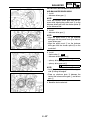
Crankshaft
2.0 × 2.9 mm (0.079 × 0.114 in)
0.20 ~ 0.50 mm (0.008 ~ 0.020 in)
C1
-------
C2
E
D
A
Crank width “A”
Runout limit C1
C2
61.95 ~ 62.00 mm (2.439 ~ 2.441 in)
0.03 mm (0.0012 in)
0.03 mm (0.0012 in)
Big end side clearance “D”
0.15 ~ 0.45 mm (0.0059 ~ 0.0177 in)
Big end radial clearance “E”
0.010 ~ 0.025 mm (0.0004 ~ 0.0010 in)
2-7
---0.05 mm
(0.002 in)
0.05 mm
(0.002 in)
0.50 mm
(0.0197 in)
----
ENGINE SPECIFICATIONS
Item
Balancer
Balancer drive method
Clutch
Friction plate 1 (inside dia.: 120 mm)
Thickness
Quantity
Friction plate 2 (inside dia.: 128 mm)
Thickness
SPEC
Standard
Gear
2.9 ~ 3.1 mm (0.114 ~ 0.122 in)
7
2.9 ~ 3.1 mm (0.114 ~ 0.122 in)
----
2.8 mm
(0.110 in)
---2.8 mm
(0.110 in)
----
Quantity
Clutch plate
Thickness
Quantity
Max. warpage
1.5 ~ 1.7 mm (0.059 ~ 0.067 in)
7
----
------0.2 mm
(0.0079 in)
Clutch spring
Free length
51.8 mm (2.04 in)
50.0 mm
(1.97 in)
----------------
Quantity
Clutch housing thrust clearance
Clutch housing radial clearance
Clutch release method
Push rod 2 bending limit
Transmission
Main axle deflection limit
Drive axle deflection limit
1
Limit
6
0.10 ~ 0.35 mm (0.0039 ~ 0.0138 in)
0.010 ~ 0.044 mm (0.0004 ~ 0.0017 in)
Inner push, cam push
0.1 mm (0.004 in)
----
0.08 mm
(0.0031 in)
0.08 mm
(0.0031 in)
----
Shifter
Shifter type
Max. shift fork guide bar bending
Shift drum and guide bar
----
Decompression device
Device type
Air filter oil grade
Auto decomp
Engine oil
2-8
---0.05 mm
(0.002 in)
-------
ENGINE SPECIFICATIONS
Item
Carburetor
I. D. mark
Main jet
Main air jet
Jet needle/clip position
Cutaway
Pilot air jet
Pilot outlet
Pilot jet
Bypass 1
Valve seat size
Starter jet
Float height
Engine idle speed
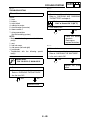
Intake vacuum
Standard
(M.J)
(M.A.J)
(J.N)
(C.A)
(P.A.J.1)
(P.O)
(P.J)
(B.P.1)
(V.S)
(G.S.1)
(F.H)
Throttle position sensor
Resistance
Oil filter type
Oil pump
Oil pump type
Inner-rotor-to-outer-rotor-tip clearance
Outer-rotor-to-oil-pump-housing
clearance
Bypass valve setting pressure
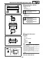
Cooling system
Radiator core
Width
Height
Depth
Radiator cap opening pressure
Radiator capacity
Coolant reservoir
Capacity
From low to full level
Water pump
Type
SPEC
Limit
5TG1 00
#158
ø1.0
NDSR/4
1.5
#100
ø0.9
#42
ø1.0
ø3.8
#90
8 mm (0.31 in)
1,750 ~ 1,850 r/min
34.7 ~ 37.3 kPa
(260 ~ 280 mmHg, 10.2 ~ 11.0 inHg)
-------------------------------------------
4 ~ 6 kΩ at 20 °C
Paper
-------
Trochoid
0.07 ~ 0.12 mm (0.0028 ~ 0.0047 in)
0.09 ~ 0.17 mm (0.0035 ~ 0.0067 in)
40.0 ~ 80.0 kPa
(300 ~ 602 mmHg, 11.8 ~ 23.7 inHg)
---0.20 mm
(0.0079 in)
0.24 mm
(0.0094 in)
----
300 mm (11.8 in)
188 mm (7.4 in)
24 mm (0.94 in)
107.9 ~ 137.3 kPa
(1.079 ~ 1.373 kg/cm2, 15.35 ~ 19.53 psi)
0.58 L (0.51 Imp qt, 0.61 US qt)
----
0.29 L (0.26 Imp qt, 0.31 US qt)
0.16 L (0.14 Imp qt, 0.17 US qt)
-------
Single-suction centrifugal pump
----
2-9
-------------
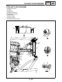
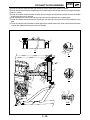
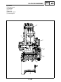
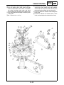
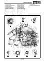
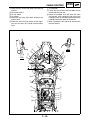
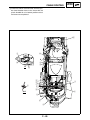
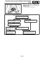
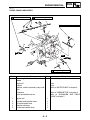
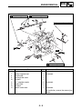
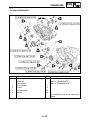
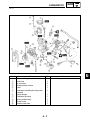
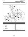
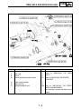
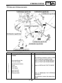
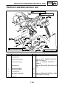
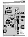
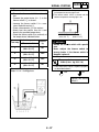
ENGINE SPECIFICATIONS
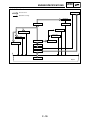
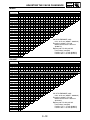
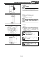
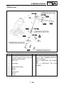
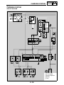
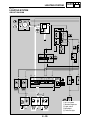
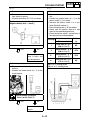
SPEC
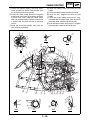
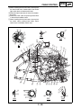
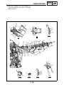
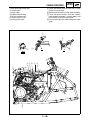
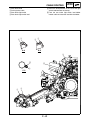
Lubrication chart
Oil tank
Pressure feed
Splashed scavenge
Camshaft
Valve lifter
Cylinder head
Piston
Transmission gears
Piston pin
Main axle
Oil filter
Crank pin
Drive axle
Check ball
Oil pump rotor 1
Oil pump rotor 2
Oil strainer
Oil pan
2 - 10
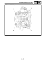
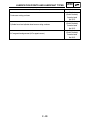
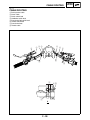
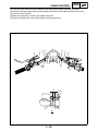
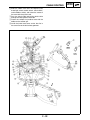
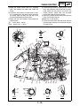
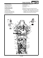
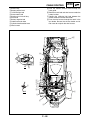
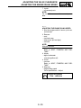
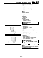
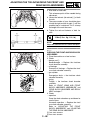
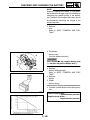
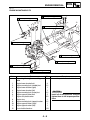
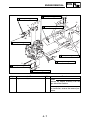
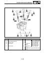
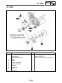
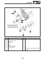
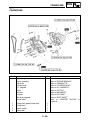
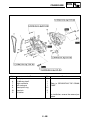
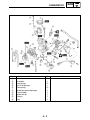
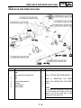
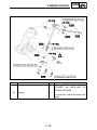
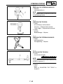
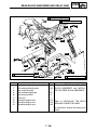
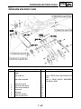
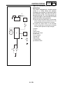
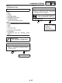
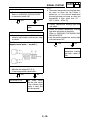
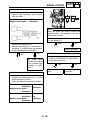
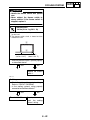
ENGINE SPECIFICATIONS
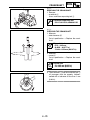
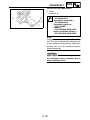
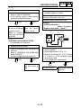
Cylinder head tightening sequence
2 - 11
SPEC
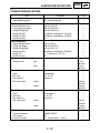
CHASSIS SPECIFICATIONS
SPEC
EBS01003
CHASSIS SPECIFICATIONS
Item
Steering system
Steering bearing type
Front suspension
Shock absorber travel
Fork spring free length
Spring fitting length
Spring rate (K1)
Spring rate (K2)
Optional spring
Rear suspension
Shock absorber travel
Spring free length
Spring fitting length
Spring rate (K1)
Stroke (K1)
Optional spring
Swingarm
Free play limit
Front wheel
Type
Rim size
Rim material
Rim runout limit
Rear wheel
Type
Rim size
Rim material
Rim runout limit
Drive chain
Type/manufacturer
Link quantity
Drive chain slack
Standard
Limit
Ball and race bearing
----
110 mm (4.33 in)
265 mm (10.43 in)
255 mm (10.04 in)
19.6 N/mm (2.00 kg/mm, 112 lb/in)
39.2 N/mm (4.00 kg/mm, 224 lb/in)
No
-------------------
116.0 (4.57 in)
259 mm (10.20 in)
244 mm (9.61 in)
46.0 N/mm (4.69 kg/mm, 263 lb/in)
0 ~ 116.0 mm (0 ~ 4.57 in)
No
-------------------
end
----
1 mm
(0.04 in)
1 mm
(0.04 in)
side
----
radial
Panel wheel
10 × 5.5 AT
Aluminum
----
lateral
----
radial
Panel wheel
9 × 8.5 AT
Aluminum
----
lateral
----
520MXV/DAIDO
96
25 ~ 35 mm (0.98 ~ 1.38 in)
2 - 12
---------2.0 mm
(0.08 in)
2.0 mm
(0.08 in)
---------2.0 mm
(0.08 in)
2.0 mm
(0.08 in)
----------
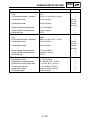
CHASSIS SPECIFICATIONS
Item
Front disc brake
Type
Disc outside diameter × thickness
Pad thickness inner
Pad thickness outer
Master cylinder inside diameter
Caliper cylinder inside diameter
Brake fluid type
Rear disc brake
Type
Disc outside diameter × thickness
Pad thickness inner
Pad thickness outer
Master cylinder inside diameter
Caliper cylinder inside diameter
Brake fluid type
Brake lever and brake pedal
Brake pedal position
Parking brake cable end length
Clutch lever free play (lever end)
Throttle lever free play
Speed limiter length
Shift pedal height
Standard
Dual
161.0 × 3.5 mm (6.34 × 0.14 in)
4.5 mm (0.18 in)
4.5 mm (0.18 in)
12.7 mm (0.50 in)
27 mm (1.06 in)
DOT 4
Single
200.0 × 3.6 mm (7.87 × 0.14 in)
4.5 mm (0.18 in)
4.5 mm (0.18 in)
12.7 mm (0.50 in)
33.96 mm (1.34 in)
DOT 4
11.7 mm (0.46 in)
56 ~ 60 mm (2.20 ~ 2.36 in)
8 ~ 13 mm (0.31 ~ 0.51 in)
2 ~ 4 mm (0.08 ~ 0.16 in)
Less than 12 mm (0.47 in)
25 mm (0.98 in)
2 - 13
SPEC
Limit
------1.0 mm
(0.04 in)
1.0 mm
(0.04 in)
---------------1.0 mm
(0.04 in)
1.0 mm
(0.04 in)
----------------------------
ELECTRICAL SPECIFICATIONS
SPEC
EBS01004
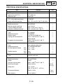
ELECTRICAL SPECIFICATIONS
Item
Standard
Voltage
Ignition system
Ignition timing (B.T.D.C.)
Advancer type
C.D.I.
C.D.I. unit model/manufacturer
Pickup coil resistance/color
Ignition coil
Model/manufacturer
Minimum ignition spark gap
Primary winding resistance
Secondary winding resistance
Charging system
Type
Model/manufacturer
Nominal output
Lighting coil resistance/color
Charging coil resistance/color
Rectifier/regulator
Type
Model/manufacturer
No load regulated voltage
Rectifier capacity
Electric starter system
Type
Starter motor
Model/manufacturer
Output
Armature coil resistance
Brush overall length
Spring force
(DC)
(AC)
(DC)
(AC)
Limit
12 V
----
7.5°/1,800 r/min
Digital type
-------
5TG/MORIC
248 ~ 372 Ω at 20 °C (68 °F) red–white
-------
J0474/DENSO
6 mm (0.24 in)
0.08 ~ 0.10 Ω at 20 °C (68 °F)
4.56 ~ 6.84 kΩ at 20 °C (68 °F)
-------------
A.C. magneto
F5TG/MORIC
14 V 120 W at 5,000 r/min
0.224 ~ 0.336 Ω at 20 °C (68 °F)
yellow–ground
0.288 ~ 0.432 Ω at 20 °C (68 °F)
white–ground
-------------
Semi conductor-short circuit
SH712AB/SHINDENGEN
14.1 ~ 14.9 V
13.0 ~ 14.0 V
8.0 A
12.0 A
-------------------
Constant mesh type
----
SM-14/MITSUBA
0.5 kW
0.004 ~ 0.005 Ω at 20 °C (68 °F)
10 mm (0.39 in)
Commutator diameter
7.16 ~ 9.52 N
(730 ~ 971 gf, 25.77 ~ 34.27 oz)
28 mm (1.10 in)
Mica undercut
0.7 mm (0.03 in)
2 - 14
----
---------3.5 mm
(0.14 in)
---27 mm
(1.06 in)
----
ELECTRICAL SPECIFICATIONS
Item
Starter relay
Model/manufacturer
Amperage rating
Coil winding resistance
Thermo switch
Thermo switch 1
Model/manufacturer
Opening temperature
Closing temperature
Thermo switch 2
Model/manufacturer
Opening temperature
Closing temperature
Circuit breaker
Type
Amperage for individual circuit
Fuse
Reserve
Standard
SPEC
Limit
2768079-A/JIDECO
180 A
4.18 ~ 4.62 Ω
----------
5GH/NIPPON THERMOSTAT
95 ~ 101 °C (203.0 ~ 213.8 °F)
89 ~ 95 °C (192.2 ~ 203.0 °F)
----------
5LP/NIPPON THERMOSTAT
117 ~ 123 °C (242.6 ~ 253.4 °F)
112 ~ 118 °C (233.6 ~ 244.4 °F)
----------
Fuse
----
15 A × 1
15 A × 1
-------
2 - 15
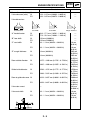
TIGHTENING TORQUES
SPEC
EBS01005
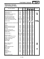
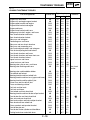
TIGHTENING TORQUES
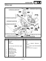
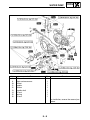
ENGINE TIGHTENING TORQUES
Part to be tightened
Part name
Thread
Q’ty
size
Spark plug
Cylinder head cover
Camshaft cap
Cylinder head blind plug screw
Timing chain tensioner
Timing chain tensioner cap
Timing chain guide (intake)
Cylinder head (exhaust pipe)
Cylinder head (timing chain side)
Cylinder head
—
M10S 1
Bolt
M6
2
Bolt
M6
10
Screw
M12
1
Bolt
M6
2
Bolt
M6
1
Bolt
M6
2
Stud bolt
M8
1
Stud bolt
M6
2
Bolt
M10
4
Nut
M6
2
Parking brake cable and clutch cable
Bolt
M6
1
holder
Cylinder
Bolt
M6
1
Engine oil drain bolt (oil tank)
Bolt
M8
1
Engine oil drain bolt (engine)
Bolt
M10
1
Oil pump
Bolt
M6
3
Oil pump housing cover
Screw
M4
1
Engine oil drain bolt (oil filter)
Bolt
M6
1
Oil filter cover
Bolt
M6
2
Oil delivery pipe 1
Union bolt M10
1
Union bolt M8
2
Oil delivery pipe 2
Bolt
M6
1
Oil pipe 1 and crankcase cover
Bolt
M6
1
Oil pipe 2 and left crankcase
Bolt
M6
1
Oil pipe 2 and oil tank
Bolt
M6
1
Oil gallery bolt
Bolt
M6
1
Exhaust pipe
Bolt
M8
1
Nut
M8
1
Exhaust pipe protector
Screw
M6
2
Muffler protector
Screw
M6
2
Muffler
Bolt
M8
2
Muffler and exhaust pipe
Bolt
M8
1
Spark arrester
Bolt
M6
1
Silencer cap
Bolt
M6
1
Radiator
Bolt
M6
4
Radiator fan
Bolt
M6
3
Coolant drain bolt
Bolt
M6
1
Impeller
—
M8
1
Water pump inlet pipe
Bolt
M6
1
2 - 16
Tightening torque
Nm m · kg ft · lb
13
1.3
9.4
10
1.0
7.2
10
1.0
7.2
37
3.7
27
10
1.0
7.2
7
0.7
5.1
10
1.0
7.2
15
1.5
11
7
0.7
5.1
See NOTE. *1
10
1.0
7.2
10
1.0
7.2
10
19
20
10
2
10
10
20
18
10
8
8
10
10
24
13
7
7
34
20
10
10
7
9
10
14
10
1.0
1.9
2.0
1.0
0.2
1.0
1.0
2.0
1.8
1.0
0.8
0.8
1.0
1.0
2.4
1.3
0.7
0.7
3.4
2.0
1.0
1.0
0.7
0.9
1.0
1.4
1.0
7.2
13
14
7.2
1.4
7.2
7.2
14
13
7.2
8
8
7.2
7.2
17
9.4
5.1
5.1
24
14
7.2
7.2
5.1
6.5
7.2
10
7.2
Remarks
E
LT
M
LT
LT
LT
TIGHTENING TORQUES
Part to be tightened
Part name
Thread
Q’ty
size
SPEC
Tightening torque
Nm m · kg ft · lb
Cylinder head water jacket
Water pump housing cover
Coolant reservoir
Clutch cover
Clutch spring
Clutch boss
Bolt
Bolt
Bolt
Bolt
Bolt
Nut
M6
M6
M6
M6
M6
M20
1
4
2
7
6
1
10
10
7
10
8
75
1.0
1.0
0.7
1.0
0.8
7.5
7.2
7.2
5.1
7.2
8
54
Push lever shaft plate
Clutch cable holder
Crankcase cover
Parking brake cable holder and
crankcase cover
Left crankcase
Oil strainer
Crankcase bearing retainer
Bolt
Bolt
Bolt
Bolt
M6
M6
M6
M6
1
1
8
2
10
10
10
10
1.0
1.0
1.0
1.0
7.2
7.2
7.2
7.2
Bolt
Bolt
Screw
Screw
Bolt
Nut
M6
M6
M6
M6
M6
M20
11
2
3
4
7
1
12
10
12
12
10
75
1.2
1.0
1.2
1.2
1.0
7.5
8.7
7.2
8.7
8.7
7.2
54
Balancer driven gear
Nut
M14
1
50
5.0
36
Drive sprocket
Nut
M20
1
75
7.5
54
Bolt
Bolt
Bolt
Nut
Bolt
Bolt
Bolt
Bolt
Bolt
Bolt
Bolt
Bolt
Bolt
Screw
M6
M6
M6
M12
M5
M5
M6
M6
M8
M6
M6
M6
M5
M5
2
2
9
1
2
2
2
6
1
2
1
1
2
1
10
10
10
65
7
7
10
16
30
10
10
12
4
3
1.0
1.0
1.0
6.5
0.7
0.7
1.0
1.6
3.0
1.0
1.0
1.2
0.4
0.4
7.2
7.2
7.2
47
5.1
5.1
7.2
11
22
7.2
7.2
8.7
2.9
2.9
Screw
M4
1
3
0.3
2.2
Screw
M6
1
3
0.3
2.2
—
—
M10
M18
1
1
20
28
2.0
2.8
14
20
Primary drive gear
Drive axle oil seal retainer
Torque limiter cover
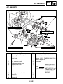
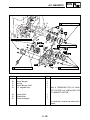
A.C. magneto cover
A.C. magneto rotor
Stator coil
A.C. magneto lead holder
Pickup coil
Starter clutch
Shift drum segment
Shift guide
Stopper lever
Shift pedal
Throttle cable cover (carburetor)
Carburetor joint clamp screw (carburetor side)
Carburetor joint clamp screw (cylinder head side)
Carburetor clamp screw (air intake
duct side)
Neutral switch
Thermo switch 1
2 - 17
Remarks
Use a lock
washer.
LT
LT
Use a lock
washer.
Use a lock
washer.
Use a lock
washer.
LT
LT
LT
LT
TIGHTENING TORQUES
Part to be tightened
Part name
Thermo switch 2
Starter motor
Starter motor lead
Bush holder assembly and rear
bracket nut
—
Bolt
Nut
Nut
Thread
Q’ty
size
M18
M6
M6
M6
1
2
1
1
SPEC
Tightening torque
Nm m · kg ft · lb
28
10
7
7
2.8
1.0
0.7
0.7
Remarks
20
7.2
5.1
5.1
NOTE:
*1: Tighten the cylinder head bolts to 30 Nm (3.0 m · kg, 22 ft · lb) in the proper tightening sequence,
remove and retighten the cylinder head bolts to 20 Nm (2.0 m · kg, 14 ft · lb) in the proper tightening
sequence, and then tighten the cylinder head bolts further in two steps of 90° to reach the specified
angle of 180° in the proper tightening sequence.
2 - 18
TIGHTENING TORQUES
SPEC
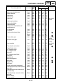
EBS01006
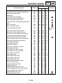
CHASSIS TIGHTENING TORQUES
Part to be tightened
Thread size
Tightening torque
Nm m · kg ft · lb
Engine stay and frame
Engine stay and engine upper bracket
Engine upper bracket and engine
Engine lower bracket and engine
Engine and frame
Engine lower bracket and frame
Swingarm pivot shaft, engine, and frame
Rear shock absorber and frame
Rear shock absorber locknut
Relay arm and swingarm
Connecting arm and frame
Relay arm and rear shock absorber
Relay arm and connecting arm
Hub, brake caliper bracket, and swingarm
Drive chain adjusting bolt and locknut
Front shock absorber and frame
Front shock absorber and lower front arm
Front shock absorber locknut
Upper front arm and frame
Lower front arm and frame
Steering stem, pitman arm, and frame
Steering stem bushing and frame
M8
M8
M10
M10
M10
M8
M16
M12
M50
M12
M12
M12
M12
M12
M8
M10
M10
M50
M10
M10
M14
M8
33
26
40
66
66
38
100
80
45
55
55
43
55
85
16
45
45
30
38
55
180
23
3.3
2.6
4.0
6.6
6.6
3.8
10
8.0
4.5
5.5
5.5
4.3
5.5
8.5
1.6
4.5
4.5
3.0
3.8
5.5
18
2.3
Steering stem and handlebar holder
Tie-rod end and locknut
Steering knuckle and front wheel hub
Steering knuckle and front arm (upper and lower)
Steering knuckle and tie-rod ball joint
Pitman arm and tie-rod ball joint
Frame and bearing retainer
Fuel tank and fuel cock
Fuel tank and frame
Front wheel and front wheel hub
Steering knuckle and front brake caliper bracket
Front brake disc and front wheel hub
Rear axle and rear wheel hub
Rear brake caliper and brake caliper bracket
Rear wheel and rear wheel hub
Driven sprocket and sprocket bracket
Front brake pipe nut
Front brake master cylinder and handlebar
Parking brake lever and clutch lever
M8
M10
M14
M10
M10
M10
M42
M6
M6
M10
M8
M8
M14
M8
M10
M10
M10
M6
M6
23
15
70
25
25
25
65
4
7
45
28
28
120
31
45
55
19
7
7
2.3
1.5
7.0
2.5
2.5
2.5
6.5
0.4
0.7
4.5
2.8
2.8
12
3.1
4.5
5.5
1.9
0.7
0.7
2 - 19
Remarks
24
19
29
48
48
27
72
58
32
40
40
31
40
61
11
32
32
22
27
40
130
17 Use a lock
washer.
17
11
50
18
18
18
47
2.9
5.1
32
20
LT
20
85
22
32
40
13
5.1
5.1
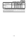
TIGHTENING TORQUES
Part to be tightened
Thread size
Tightening torque
Nm m · kg ft · lb
Front brake master cylinder and brake lever
Front brake master cylinder and brake hose
Brake hose joint and frame
Bleed screw
Front brake pad retaining bolt
Front brake caliper and brake hose
Rear brake caliper retaining bolt
Parking brake case bracket and parking brake
case
Rear axle ring nut
Rear axle ring nut set bolt
Rear brake pad retaining bolt
M36
M6
M8
100
7
18
10.0
0.7
1.8
72
5.1
13
Rear brake caliper and brake hose
Rear brake master cylinder and frame
Rear brake master cylinder and brake hose
Parking brake adjusting bolt and locknut
Rear brake disc and brake disc bracket
Rear brake fluid reservoir cover and bracket
Rear brake fluid reservoir and bracket
Front bumper and frame
Front fender and frame
Side cover and frame
Side cover, rear fender, and frame
Rear fender and frame
Rear fender stay and rear fender
Front fender stay and front fender
Rear carrier bar and frame
Footrest and frame
Foot protector and footrest
Foot protector and footrest
Foot protector and frame
Battery holding bracket and frame
Air filter case and frame
Carburetor joint clamp screw
Headlight and frame
Tail/brake light bracket and frame
Tail/brake light bracket and tail/brake light
Drive chain guide roller and frame
Engine skid plate and frame
Main frame and rear frame
M10
M8
M10
M8
M8
M6
M6
M8
M6
M6
M6
M6
M6
M6
M8
M10
M6
M8
M8
M6
M6
M4
M6
M6
M6
M8
M6
M10
30
20
30
16
28
11
4
31
7
7
7
7
7
7
33
65
13
16
16
7
7
3
7
7
7
19
7
54
3.0
2.0
3.0
1.6
2.8
1.1
0.4
3.1
0.7
0.7
0.7
0.7
0.7
0.7
3.3
6.5
1.3
1.6
1.6
0.7
0.7
0.3
0.7
0.7
0.7
1.9
0.7
5.4
22
14
22
11
20
8
2.9
22
5.1
5.1
5.1
5.1
5.1
5.1
24
48
9.4
11
11
5.1
5.1
2.2
5.1
5.1
5.1
13
5.1
39
2 - 20
M6
M10
M6
M8
M10
M10
M8
M8
SPEC
6
27
10
6
18
27
23
23
0.6
2.7
1.0
0.6
1.8
2.7
2.3
2.3
4.3
19
7.2
4.3
13
19
17
17
Remarks
LT
LT
LT
LT
LT
Use a lock
washer.
LT
LT
E
HOW TO USE THE CONVERSION TABLE/
GENERAL TIGHTENING TORQUE SPECIFICATIONS
SPEC
EBS00022
EBS00023
HOW TO USE THE CONVERSION
TABLE
GENERAL TIGHTENING TORQUE
SPECIFICATIONS
All specification data in this manual are listed
in SI and METRIC UNITS.
Use this table to convert METRIC unit data to
IMPERIAL unit data.
This chart specifies tightening torques for standard fasteners with a standard ISO thread
pitch. Tightening torque specifications for special components or assemblies are provided
for each chapter of this manual. To avoid
warpage, tighten multi-fastener assemblies in
a crisscross pattern and progressive stages
until the specified tightening torque is reached.
Unless otherwise specified, tightening torque
specifications require clean, dry threads. Components should be at room temperature.
Ex.
METRIC
MULTIPLIER
IMPERIAL
** mm
×
0.03937
=
** in
2 mm
×
0.03937
=
0.08 in
CONVERSION TABLE
METRIC TO IMPERIAL
Metric unit
Multiplier
Imperial unit
m · kg
m · kg
cm · kg
cm · kg
7.233
86.794
0.0723
0.8679
ft · lb
in · lb
ft · lb
in · lb
Weight
kg
g
2.205
0.03527
lb
oz
Speed
km/hr
0.6214
mph
Distance
km
m
m
cm
mm
0.6214
3.281
1.094
0.3937
0.03937
mi
ft
yd
in
in
Volume/
Capacity
cc (cm3)
cc (cm3)
lt (liter)
lt (liter)
0.03527
0.06102
0.8799
0.2199
oz (IMP liq.)
cu · in
qt (IMP liq.)
gal (IMP liq.)
Misc.
kg/mm
kg/cm2
Centigrade
(°C)
55.997
14.2234
9/5+32
lb/in
psi (lb/in2)
Fahrenheit
(°F)
Torque
A: Distance between flats
B: Outside thread diameter
A
(nut)
2 - 21
B
(bolt)
General tightening
torques
Nm
m · kg
ft · lb
10 mm
6 mm
6
0.6
4.3
12 mm
8 mm
15
1.5
11
14 mm
10 mm
30
3.0
22
17 mm
12 mm
55
5.5
40
19 mm
14 mm
85
8.5
61
22 mm
16 mm
130
13.0
94
LUBRICATION POINTS AND LUBRICANT TYPES
SPEC
EBS00024
LUBRICATION POINTS AND LUBRICANT TYPES
ENGINE
Lubrication point
Lubricant
Oil seal lips
LS
O-rings
LS
Bearings
E
Crankshaft pins
E
Valve stems (intake and exhaust)
M
Valve stem ends (intake and exhaust)
M
Valve lifters (intake and exhaust)
E
Camshafts (intake and exhaust)
M
Camshaft cap bolt
E
Cylinder head bolt
M
Piston surfaces
E
Piston pins
M
Auto decomp
E
Auto decompression lever
E
Water pump impeller shaft
E
Oil pump rotors (inner and outer) and oil pump housing
E
Oil pump drive gear
E
Connecting rod (bearing)
E
Torque limiter
E
Starter idle gear inner surface and shaft
E
Starter clutch inner surface
E
Primary driven gear
E
Push rod 1, 2 and ball
E
Push lever shaft
E
Push rod bearing and plane washer
E
Transmission gears (wheel and pinion)
M
Shift forks and shift fork guide bars
E
Transmission gears (wheel and pinion) splines
E
Shift drum shaft
E
Shift shaft
E
Shift shaft assembly
E
Sealant
(Quick Gasket®)
Yamaha bond
No.1215
Cylinder head cover mating surface
2 - 22
LUBRICATION POINTS AND LUBRICANT TYPES
Lubrication point
SPEC
Lubricant
Crankcase mating surfaces
Sealant
(Quick Gasket®)
Yamaha bond
No.1215
Cylinder head and cylinder head cover mating surfaces
Sealant
(Quick Gasket®)
Yamaha bond
No.1215
AC magneto lead grommet (AC magneto cover)
Sealant
(Quick Gasket®)
Yamaha bond
No.1215
2 - 23
SPEC
COOLANT FLOW DIAGRAMS
EBS00025
COOLANT FLOW DIAGRAMS
1 Radiator inlet hose
2 Radiator
3 Radiator fan
4 Radiator outlet hose
5 Water pump inlet pipe
6 Water pump
7 Thermo switch 1
8 Thermo switch 2
9 Cylinder head water jacket
7
8
A
Ì
Í
B
A
1
B
D
2
C
Ê
4
Ë
D
3
È
C
É
5
Ê
Î
6
D-D
2 - 24
9
SPEC
COOLANT FLOW DIAGRAMS
È Install the radiator outlet hose with the white paint mark parallel to the ground as shown.
É Install the radiator outlet hose completely on the radiator pipe until the hose contacts the flange of the pipe.
Ê 30 mm (1.18 in)
Ë Install the radiator outlet hose onto the water pump inlet pipe until the end of the hose reaches the middle
of the blue paint mark on the pipe.
Ì Align the white paint mark on the radiator inlet hose with the projection on the radiator pipe.
Í Install the radiator inlet hose onto the radiator pipe until the end of the hose contacts the projection of the
pipe.
Î Install the radiator inlet hose onto the outlet pipe of the cylinder head water jacket until the end of the hose
reaches the middle of the blue paint mark on the pipe.
7
8
A
Ì
Í
B
A
1
B
D
2
C
Ê
4
Ë
D
3
È
C
É
5
Ê
Î
6
D-D
2 - 25
9
OIL FLOW DIAGRAMS
SPEC
EBS00026
OIL FLOW DIAGRAMS
1 Intake camshaft
2 Exhaust camshaft
3 Oil filter element
4 Oil tank
5 Oil pipe 1
6 Oil pipe 2
7 Main axle
8 Drive axle
9 Oil delivery pipe 1
0 Oil pump
A Oil strainer
A
1
2
A
9
4
3
3
B
C
B
C
8
B-B
7
6
5
A
0
C-C
2 - 26
SPEC
OIL FLOW DIAGRAMS
1 Camshaft
2 Oil filter element
3 Crankshaft
4 Main axle
5 Drive axle
6 Oil delivery pipe 2
7 Connecting rod
1
7
2
3
4
5
6
2 - 27
CABLE ROUTING
EBS00028
CABLE ROUTING
1 Parking brake cable
2 Clutch cable
3 Clutch switch lead
4 Handlebar switch lead
5 Front brake light switch lead
6 Throttle switch lead
7 Front brake hose
8 Throttle cable
1
4
2 3
5 6
7
É
È
A
Ê
Ì
A
2 - 28
6Ë
8
SPEC
CABLE ROUTING
SPEC
È Fasten the clutch switch lead and handlebar switch lead to the handlebar with the plastic band.
É Fasten the front brake light switch lead and throttle switch lead to the handlebar with the plastic band.
Ê Less than 10 mm (0.39 in)
Ë Make sure that there is no slack in the throttle switch lead.
Ì Fasten the throttle switch lead to the handlebar with the plastic band.
1
4
2 3
5 6
7
É
È
A
Ê
Ì
A
2 - 29
6Ë
8
CABLE ROUTING
1 Throttle cable
2 Front brake hose
3 Front brake light switch lead
4 Throttle switch lead
5 Clutch cable
6 Parking brake cable
7 Clutch switch lead
8 Handlebar switch lead
9 Radiator fan breather hose
0 Thermo switch 2 lead
A Headlight coupler (left)
B C.D.I. unit leads
C Rectifier/regulator coupler
D Brake pipe
E Rectifier/regulator
F C.D.I. unit
G Diode 1
H Diode 2
I Thermo switch 1 lead
J Headlight coupler (right)
K Main switch coupler
2 - 30
SPEC
CABLE ROUTING
È Pass the throttle cable through the cable guide.
É Pass the throttle cable, leads (front brake light
switch, throttle switch, clutch switch, and handlebar switch), parking brake cable, and clutch
cable through the cable guide in the order listed.
Ê Pass the throttle cable through the steering stem
cable guide.
Ë 30 ~ 50 mm (1.18 ~ 1.97 in)
SPEC
Ì Fasten the front brake light switch lead, throttle
switch lead, clutch switch lead, and handlebar
switch lead with the plastic band and then place
the end of the band under the fuel tank cover.
Í Pass the radiator fan breather hose through the
hose guide.
Î Fasten the radiator fan breather hose, clutch
cable, and parking brake cable with the clamp.
2 - 31
CABLE ROUTING
Ï Slide the rubber cover over the couplers (front
brake light switch, throttle switch, clutch switch,
and handlebar switch) and fasten the center of
the cover with the plastic band.
Ð Pass the clutch cable and parking brake cable
through the cable guide in this order.
Ñ Fasten the radiator fan breather hose with the
holder on the radiator grill.
Ò Install the brake hose cover so that the slits in
the cover fit over the brake hose grommet.
2 - 32
SPEC
CABLE ROUTING
1 Indicator coupler
2 Radiator fan motor coupler
3 Thermo switch 2
4 Fuel tank breather hose
5 Radiator fan motor lead
6 Radiator fan breather hose
7 Wire harness
8 Fuel hose
9 Throttle position sensor lead
0 Carburetor switch lead
A Crankcase breather hose
B Battery negative lead
C Starter motor lead
D Neutral switch lead
E A.C. magneto lead
F Oil tank breather hose
G Neutral switch coupler
H A.C. magneto coupler
I Front brake hose
J Throttle cable
K Parking brake cable
L Clutch cable
SPEC
M Indicator leads
N Cylinder head breather hose
Ù I
7
M
Ú
J
B-B
Û
C-C
4
A
K
Ü
A
L
2
1
È
3É
Ì
Ê
Î
C
56
7 Í
B
Ë
G
B
G
5
C
Ï
G
D
89
Ð
E
0
Ñ
D
G
Ò
E
A
B
C
Ó
F
H
D
E
G-G
G
F
Ø
× F
Ö E Õ Ô D
E
7
D
N
E-E
F-F
2 - 33
0
D-D
9
CABLE ROUTING
SPEC
Í Fasten the wire harness, throttle position sensor
lead, and carburetor switch lead with the plastic
band. Make sure that there is no slack in the
throttle position sensor lead and carburetor
switch lead along the frame as shown.
Î Install the cylinder head breather hose with the
paint mark facing to the left.
Ï More than 15 mm (0.59 in)
Ð Fasten the wire harness with the plastic band on
the white tape and then face the end of the plastic band inward.
È Route the neutral switch lead, A.C. magneto
lead, and radiator fan motor lead under the
frame.
É Fasten the wire harness, thermo switch 2 lead,
A.C. magneto lead, and neutral switch lead with
the plastic band and then face the end of the
band inward between the frame tubes.
Ê Route the fuel tank breather hose behind the
steering stem.
Ë 7 ~ 21 mm (0.28 ~ 0.83 in)
Ì 50 ~ 70 mm (1.97 ~ 2.76 in)
Ù I
7
M
Ú
J
B-B
Û
C-C
4
A
K
Ü
A
L
2
1
È
3É
Ì
Ê
Î
C
56
7 Í
B
Ë
G
B
G
5
C
Ï
G
D
89
Ð
E
0
Ñ
D
G
Ò
E
A
B
C
Ó
F
H
D
E
G-G
G
F
Ø
× F
Ö E Õ Ô D
E
7
D
N
E-E
F-F
2 - 34
0
D-D
9
CABLE ROUTING
SPEC
Ô Fasten the neutral switch lead with the lead
holder.
Õ Fasten the neutral switch lead with the clamp.
Ö Fasten the A.C. magneto lead with the lead
holder.
× Fasten the neutral switch lead and A.C. magneto lead with the plastic band. Face the end of
the plastic band inward on top of the frame.
Ø Pass the neutral switch lead and A.C. magneto
lead through the guide on the fender stay.
Ñ Fasten the negative battery lead and starter
motor lead with the plastic band and then face
the end of the plastic band inward.
Ò Fasten the starter motor lead to the negative
battery lead at the mark on the battery lead with
a plastic band. Then, fasten the starter motor
lead and negative battery lead to the frame with
a plastic band and face the end of the band
inward.
Ó Install the crankcase breather hose with the
paint mark facing outward.
Ù I
7
M
Ú
J
B-B
Û
C-C
4
A
K
Ü
A
L
2
1
È
3É
Ì
Ê
Î
C
56
7 Í
B
Ë
G
B
G
5
C
Ï
G
D
89
Ð
E
0
Ñ
D
G
Ò
E
A
B
C
Ó
F
H
D
E
G-G
G
F
Ø
× F
Ö E Õ Ô D
E
7
D
N
E-E
F-F
2 - 35
0
D-D
9
CABLE ROUTING
SPEC
Ù When installing the fuel tank cover, do not pinch
the front brake hose, throttle cable, front brake
light switch lead, or throttle switch lead.
Ú Route the front brake hose in front of the handlebar cover.
Û Route the clutch cable and parking brake cable
in front of the handlebar cover.
Ü When installing the fuel tank cover, do not pinch
the clutch cable, parking brake cable, clutch
switch lead, or handlebar switch lead.
Ù I
7
M
Ú
J
B-B
Û
C-C
4
A
K
Ü
A
L
2
1
È
3É
Ì
Ê
Î
C
56
7 Í
B
Ë
G
B
G
5
C
Ï
G
D
89
Ð
E
0
Ñ
D
G
Ò
E
A
B
C
Ó
F
H
D
E
G-G
G
F
Ø
× F
Ö E Õ Ô D
E
7
D
N
E-E
F-F
2 - 36
0
D-D
9
CABLE ROUTING
1 Wire harness
2 Air filter case breather hose
3 Cylinder head breather hose
4 Coolant reservoir breather hose
5 Coolant reservoir hose
6 Tail/brake light
7 Tail/brake light lead
8 Crankcase breather hose
9 Carburetor drain hose
0 Carburetor air vent hose
A Battery negative lead
SPEC
B Starter motor lead
È When installing the rear fender, make sure that
the rear fender does not overlap or pinch the cylinder head breather hose, coolant reservoir
hose, or wire harness.
É Install the air filter case breather hose with the
paint mark facing outward.
Ê Install the cylinder head breather hose with the
paint mark facing outward.
0
Ñ
9
A
B
9
8
A
Ò
Ð
C-C
B
Ï
A
È
1
3Ê Ë 4 Ì5
2É
G
F
E
D
6
D
C
F
Í
E
A
8
Î
C
G7
B
5
3
A
B
1
7
5
4
G-G
7
F-F
2 - 37
E-E
D-D
CABLE ROUTING
SPEC
Ï Pass the carburetor drain hose and carburetor
air vent hoses through the hose guide on the
engine from the left side of the machine in the
order listed. Do not pinch the hoses.
Ð Route the negative battery lead to the outside of
the carburetor air vent hose and to the inside of
the carburetor drain hose.
Ñ Route the carburetor drain hose between the
rear shock absorber and swingarm, and then
under the frame.
Ë Install the coolant reservoir breather hose without twisting the hose.
Ì Fasten the coolant reservoir hose and the coolant reservoir breather hose with a clamp. Do not
pinch the coolant reservoir breather hose.
Í Install the coolant reservoir breather hose as
shown so that there is no slack.
Î Install the wire harness so that it does not hang
from the rear fender.
0
Ñ
9
A
B
9
8
A
Ò
Ð
C-C
B
Ï
A
È
1
3Ê Ë 4 Ì5
2É
G
F
E
D
6
D
C
F
Í
E
A
8
Î
C
G7
B
5
3
A
B
1
7
5
4
G-G
7
F-F
2 - 38
E-E
D-D
CABLE ROUTING
SPEC
Ò Route the carburetor drain hose between the
frame and connecting arm and let it hang freely
under the vehicle.
0
Ñ
9
A
B
9
8
A
Ò
Ð
C-C
B
Ï
A
È
1
3Ê Ë 4 Ì5
2É
G
F
E
D
6
D
C
F
Í
E
A
8
Î
C
G7
B
5
3
A
B
1
7
5
4
G-G
7
F-F
2 - 39
E-E
D-D
SPEC
CABLE ROUTING
1 Rear brake light switch lead
2 Throttle cable
3 Clutch cable
4 Coolant reservoir hose
5 Oil tank breather hose
6 Thermo switch 1 lead
7 Parking brake cable
È Fasten the coolant reservoir hose with a clamp
so that it is not pinched.
É Route the thermo switch 1 lead under the frame.
Ê Fasten the thermo switch 1 lead with a plastic
band between the diode 1 and the diode 2 and
then face the end of the band inward.
Ë Pass the parking brake cable through the cable
guide.
3
7
1
4
7
B
C
A-A
23 È 4 5
1
A
A
A
6
A
B
C
7
2 - 40
É
Ê
Ë
CABLE ROUTING
1 Rear brake hose
2 Parking brake cable
3 Rear brake light switch
4 Rear brake light switch lead
2
1
SPEC
È Install the lead protector of the rear brake light
switch lead between the clamps.
É Face the rear brake light switch lead holder
inward and then fasten the lead with the holder.
2
1
B-B
A-A
4
É
C
È
C
4
C
C-C
3
B
1
2
B
A
A
2 - 41
C
SPEC
CABLE ROUTING
1 Rectifier/regulator
2 Headlight lead (right)
3 Main switch lead
4 Thermo switch 1 lead
5 Coolant reservoir hose
6 Oil tank breather hose
7 Throttle cable
8 Ignition coil lead
9 Rear brake light switch lead
0 Cylinder head breather hose
A Carburetor switch lead
B Throttle position sensor lead
C Wire harness
D Headlight lead (left)
E C.D.I. unit
È Route the wire harness on top of the frame.
É Route the headlight lead (right) over the frame
and connect. After connecting the lead to the
headlight, place the headlight coupler behind the
headlight toward the center of the vehicle.
E
1
È
B-B
E
Ó C
A-A
B
É
2
Ê
Ò
D
B
3
4
A
A
Ë Ì
Í
C
5
Ñ
B
6
A
7
8
Î
9
Ð
Ï
0
2 - 42
SPEC
CABLE ROUTING
Ê Route the main switch lead under the frame and
connect.
Ë To thermo switch 1
Ì To main switch
Í To radiator
Î Route the rear brake light switch lead over the
throttle cable.
Ï Route the rear brake light switch lead and ignition coil lead over the cylinder head breather
hose.
Ð To carburetor
Ñ Fasten the wire harness with the holder on the
shield under the fuel tank.
Ò Route the headlight lead (left) over the frame
and connect. After connecting the lead to the
headlight, place the headlight coupler behind the
headlight toward the center of the vehicle.
Ó When installing the left side cover, do not pinch
the wire harness.
E
1
È
B-B
E
Ó C
A-A
B
É
2
Ê
Ò
D
B
3
4
A
A
Ë Ì
Í
C
5
Ñ
B
6
A
7
8
Î
9
Ð
Ï
0
2 - 43
CABLE ROUTING
1 Starter relay
2 Battery positive lead
3 Tail/brake light lead
4 Starter motor lead
5 Starting circuit cut-off relay
6 Earth lead
7 Battery negative lead
8 Coolant reservoir hose
9 Cylinder head breather hose
0 Wire harness
SPEC
È Pass the coolant reservoir hose through the
hose guide.
É Route the earth lead and wire harness under the
battery bracket.
Ê Connect the tail/brake light lead between the
coolant reservoir and the rear fender.
Ë Pass the wire harness through the notch in the
rear fender. Be sure that the rear fender and air
filter case do not pinch the wire harness.
È
7
0
B
9
8
8
B
Ì
7
Ë
Ê A
7
6
É
1
A
2
A-A
5
4
3
2 - 44
CABLE ROUTING
SPEC
Ì Fasten the coolant reservoir hose and the cylinder head breather hose to the frame with the
plastic beaded tie at its loosest position so that
the hoses are not pinched.
È
7
0
B
9
8
8
B
Ì
7
Ë
Ê A
7
6
É
1
A
2
A-A
5
4
3
2 - 45
INTRODUCTION/
PERIODIC MAINTENANCE/LUBRICATION
CHK
ADJ
EBS00029
PERIODIC CHECKS AND ADJUSTMENTS
INTRODUCTION
This chapter includes all information necessary to perform recommended checks and adjustments.
These preventive maintenance procedures, if followed, will ensure more reliable machine operation
and a longer service life. The need for costly overhaul work will be greatly reduced. This information
applies to machines already in service as well as to new machines that are being prepared for sale.
All service technicians should be familiar with this entire chapter.
EBS00030
PERIODIC MAINTENANCE/LUBRICATION
INITIAL
ITEM
ROUTINE
1
month
Valves*
• Check valve clearance.
• Adjust if necessary.
Cooling system
• Check for coolant leakage.
• Repair if necessary.
• Replace coolant every 24 months.
Spark plug
• Check condition.
• Adjust gap and clean.
• Replace if necessary.
Air filter element
• Clean.
• Replace if necessary.
Carburetor*
• Check starter (choke) operation.
• Adjust engine idling speed.
Crankcase breather
system*
• Check breather hose for cracks or damage.
• Replace if necessary.
Exhaust system*
• Check for leakage.
• Tighten if necessary.
• Replace gasket if necessary.
Spark arrester
• Clean.
Fuel line*
• Check fuel hose for cracks or damage.
• Replace if necessary.
3
months
EVERY
6
months
6
months
Every 20~40 hours
(More often in wet or dusty areas.)
Engine oil
• Replace (Warm engine before draining).
Engine oil filter element
• Replace.
Drive chain
• Check and adjust slack/alignment/clean/lube.
Front brake*
• Check free play/operation/fluid leakage/
See NOTE.
• Correct if necessary.
Rear brake*
• Check operation/fluid leakage/See NOTE.
• Correct if necessary.
Clutch*
• Check operation.
• Adjust if necessary.
Wheels*
• Check balance/damage/runout.
• Replace if necessary.
Wheel bearings*
• Check bearing assemblies for looseness/damage.
• Replace if damaged.
Steering system*
•
•
•
•
Front and rear
suspension*
• Check operation.
• Correct if necessary.
Check operation.
Repair if damaged.
Check toe-in.
Adjust if necessary.
Upper and lower arm
• Lubricate every 6 months with lithium-soap-based
pivot and steering
grease.
shaft*
3-1
1
year
PERIODIC MAINTENANCE/LUBRICATION
CHK
ADJ
INITIAL
ITEM
ROUTINE
1
month
Rear arm pivot*
• Lubricate every 6 months with lithium-soap-based
grease.
Fittings and fasteners*
• Check all chassis fittings and fasteners.
• Correct if necessary.
Lights and
switches*
• Check operation.
• Adjust headlight beams.
*
3
months
EVERY
6
months
6
months
1
year
Since these items require special tools, data and technical skills, have a Yamaha dealer perform
the service.
EBS00031
NOTE:
• Recommended brake fluid: DOT4
• Brake fluid replacement:
1. When disassembling the master cylinder or caliper cylinder, replace the brake fluid. Normally
check the brake fluid level and add fluid as required.
2. On the inner parts of the master cylinder and caliper cylinder, replace the oil seals every two
years.
3. Replace the brake hoses every four years, or if cracked or damaged.
_
WARNING
_
Indicates a potential hazard that could result in serious injury or death.
3-2
3
SEAT, FENDERS AND FUEL TANK
CHK
ADJ
EBS00033
SEAT, FENDERS AND FUEL TANK
SEAT, FUEL TANK COVER AND SIDE COVERS
2
T.
R.
7 Nm (0.7 m • kg, 5.1 ft • Ib)
T.
R.
7 Nm (0.7 m • kg, 5.1 ft • Ib)
4
1
3
T.
R.
Order
1
Job/Part
Removing the seat, fuel tank cover
and side covers
Seat
Q’ty
1
7 Nm (0.7 m • kg, 5.1 ft • Ib)
Remarks
Remove the parts in the order listed.
NOTE:
Pull back the seat lock lever, than pull up
on the rear of the seat.
_
2
3
4
Fuel tank cover
Left side cover
Right side cover
1
1
1
For installation, reverse the removal procedure.
3-3
SEAT, FENDERS AND FUEL TANK
CHK
ADJ
EBS00034
FOOT PROTECTORS AND ENGINE SKID PLATE
T.
R.
16 Nm (1.6 m • kg, 11 ft • Ib)
T.
R.
T.
R.
13 Nm (1.3 m • kg, 9.4 ft • Ib)
13 Nm (1.3 m • kg, 9.4 ft • Ib)
2
1
3
T.
R.
16 Nm (1.6 m • kg, 11 ft • Ib)
16 Nm (1.6 m • kg, 11 ft • Ib)
T.
R.
T.
R.
Order
1
2
3
7 Nm (0.7 m • kg, 5.1 ft • Ib)
(6)
LT
Job/Part
Removing the foot protectors and
engine skid plate
Left foot protector
Right foot protector
Engine skid plate
Q’ty
Remarks
Remove the parts in the order listed.
1
1
1
For installation, reverse the removal procedure.
3-4
CHK
ADJ
SEAT, FENDERS AND FUEL TANK
EBS00036
HEADLIGHTS AND FRONT FENDER
4
5
6
T.
R.
7 Nm (0.7 m • kg, 5.1 ft • Ib)
T.
R.
7 Nm (0.7 m • kg, 5.1 ft • Ib)
T.
R.
7 Nm (0.7 m • kg, 5.1 ft • Ib)
3
1
1
2
R.
R.
1
2
3
4
5
6
T.
T.
Order
7 Nm (0.7 m • kg, 5.1 ft • Ib)
7 Nm (0.7 m • kg, 5.1 ft • Ib)
Job/Part
Q’ty
Remarks
Removing the headlight and front
Remove the parts in the order listed.
fender
Seat/fuel tank cover/side covers (left
Refer to “SEAT, FENDERS AND FUEL
and right)
TANK”.
Headlight coupler
2
Disconnect.
Left headlight
1
Right headlight
1
Main switch coupler
1
Disconnect.
Indicator light coupler
1
Disconnect.
Front fender
1
For installation, reverse the removal procedure.
3-5
CHK
ADJ
SEAT, FENDERS AND FUEL TANK
EBS00039
REAR FENDER
T.
R.
7 Nm (0.7 m • kg, 5.1 ft • Ib)
T.
R.
7 Nm (0.7 m • kg, 5.1 ft • Ib)
2
T.
1
R.
7 Nm (0.7 m • kg, 5.1 ft • Ib)
1
3
5
6
T.
R.
7 Nm (0.7 m • kg, 5.1 ft • Ib)
7
T.
R.
7 Nm (0.7 m • kg, 5.1 ft • Ib)
4
Order
1
Job/Part
Q’ty
Remarks
Removing the rear fender
Remove the parts in the order listed.
Seat/fuel tank cover/side covers (left
Refer to “SEAT, FENDERS AND FUEL
and right)
TANK”.
Battery lead
2
CAUTION:
_
First disconnect the negative lead,
then disconnect the positive lead.
2
3
4
5
6
7
Battery holding bracket
Battery
Air filter case breather hose
Clamp
Air filter case
Rear fender
1
1
1
1
1
1
Disconnect.
Loosen.
For installation, reverse the removal procedure.
3-6
SEAT, FENDERS AND FUEL TANK
CHK
ADJ
EBS00042
FUEL TANK
T.
7 Nm (0.7 m • kg, 5.1 ft • Ib)
R.
3
2
1
Order
1
Job/Part
Q’ty
Remarks
Removing the fuel tank
Remove the parts in the order listed.
Seat/fuel tank cover/side covers (left
Refer to “SEAT, FENDERS AND FUEL
and right)
TANK”.
Fuel hose (fuel cock side)
1
NOTE:
Before disconnecting the fuel hose, turn
the fuel cock to “OFF”.
_
2
Fuel tank
1
NOTE:
When installing the fuel tank, pass the
fuel tank breather hose through the hole
in the handlebar cover.
_
3
Fuel tank shield
1
For installation, reverse the removal procedure.
3-7
ADJUSTING THE VALVE CLEARANCE
CHK
ADJ
EAS00048
ENGINE
ADJUSTING THE VALVE CLEARANCE
The following procedure applies to all of the
valves.
NOTE:
• Valve clearance adjustment should be made
on a cold engine, at room temperature.
• When the valve clearance is to be measured
or adjusted, the piston must be at the Top
Dead Center (TDC) on the compression
stroke.
_
1.
•
•
•
•
3
2.
•
•
•
•
•
4
2
Remove:
seat
fuel tank cover
side covers (left and right)
fuel tank
Refer to “SEAT, FENDERS AND FUEL
TANK”.
Remove:
ignition coil 1
oil tank breather hose 2
cylinder head breather hose 3
spark plug
cylinder head cover 4
1
3.
•
•
4.
•
1
2
Remove:
timing mark accessing screw 1
crankshaft end accessing screw 2
Measure:
valve clearance
Out of specification → Adjust.
Valve clearance (cold)
Intake valve
0.10 ~ 0.15 mm
(0.0039 ~ 0.0059 in)
Exhaust valve
0.20 ~ 0.25 mm
(0.0079 ~ 0.0098 in)
3-8
ADJUSTING THE VALVE CLEARANCE
CHK
ADJ
▼▼▼▼▼▼▼▼▼▼▼▼▼▼▼▼▼▼▼▼▼▼▼▼▼▼▼▼▼▼▼▼
a. Turn the crankshaft counterclockwise.
b. When the piston is at the Top Dead Center
(TDC) on the compression stroke, align the
“I” mark a on the A.C. magneto rotor with
the stationary pointer b on the A.C. magneto cover.
b
a
NOTE:
• In order to be sure that the piston is at the
Top Dead Center (TDC) the punch mark c
on the exhaust camshaft sprocket and the
punch mark d on the intake camshaft
sprocket must align with the cylinder head
mating surface, as shown in the illustration.
• The Top Dead Center (TDC) on the compression stroke can be found when the camshaft lobes are turned away from each other.
_
c. Measure the valve clearance with a thickness gauge 1.
EX
NOTE:
If the valve clearance is incorrect, record the
measured reading.
IN
_
▲▲▲▲▲▲▲▲▲▲▲▲▲▲▲▲▲▲▲▲▲▲▲▲▲▲▲▲▲▲▲▲
5. Remove:
• intake camshaft
• exhaust camshaft
NOTE:
• Refer to “CAMSHAFTS” in chapter 4.
• When removing the timing chain and camshafts, fasten the timing chain with a wire to
retrieve it if it falls into the crankcase.
_
3-9
ADJUSTING THE VALVE CLEARANCE
CHK
ADJ
6. Adjust:
• valve clearance
▼▼▼▼▼▼▼▼▼▼▼▼▼▼▼▼▼▼▼▼▼▼▼▼▼▼▼▼▼▼▼▼
a. Remove the valve lifter 1 and the valve pad
2 with a valve lapper 3.
Valve lapper
90890-04101
NOTE:
• Cover the timing chain opening with a rag to
prevent the valve pad from falling into the
crankcase.
• Make a note of the position of each valve
lifter 1 and valve pad 2 so that they can be
installed in the correct place.
_
b. Select the proper valve pad from the following table.
Valve pad thickness
Available valve pads
range
1.20
Nos.
(0.047) ~
120 ~ 240 2.40 mm
(0.094 in)
25 thicknesses in
0.05 mm (0.002 in)
increments
NOTE:
• The thickness a of each valve pad is
marked in hundredths of millimeters on the
side that touches the valve lifter.
• Since valve pads of various sizes are originally installed, the valve pad number must be
rounded in order to reach the closest equivalent to the original.
_
c. Round off the original valve pad number
according to the following table.
3 - 10
Last digit
Rounded value
0 or 2
0
5
5
8
10
ADJUSTING THE VALVE CLEARANCE
CHK
ADJ
EXAMPLE:
Original valve pad number = 148 {thickness =
1.48 mm (0.058 in)}
Rounded value = 150
d. Locate the rounded number of the original
valve pad and the measured valve clearance in the valve pad selection table. The
point where the column and row intersect is
the new valve pad number.
NOTE:
The new valve pad number is only an approximation. The valve clearance must be measured again and the above steps should be
repeated if the measurement is still incorrect.
_
e. Install the new valve pad 1 and the valve
lifter 2.
NOTE:
• Lubricate the valve pad with molybdenum
disulfide oil.
• Lubricate the valve lifter with engine oil.
• The valve lifter must turn smoothly when
rotated by hand.
• Install the valve lifter and the valve pad in the
correct place.
_
f. Install the exhaust and intake camshafts,
timing chain and the camshaft caps.
T.
Camshaft cap bolt
10 Nm (1.0 m · kg, 7.2 ft · lb)
R.
NOTE:
• Refer to “INSTALLING THE CAMSHAFTS —
CAMSHAFTS” in chapter 4.
• Lubricate the camshaft bearings, camshaft
lobes and camshaft journals.
• First, install the exhaust camshaft.
• Align the camshaft sprocket marks with the
edge of the cylinder head.
• Turn the crankshaft counterclockwise several full turns to seat the parts.
_
g. Measure the valve clearance again.
h. If the valve clearance is still out of specification, repeat all of the valve clearance adjustment steps until the specified clearance is
obtained.
▲▲▲▲▲▲▲▲▲▲▲▲▲▲▲▲▲▲▲▲▲▲▲▲▲▲▲▲▲▲▲▲
3 - 11
ADJUSTING THE VALVE CLEARANCE
CHK
ADJ
INTAKE
MEASURED
CLEARANCE
0.00 ~ 0.04
0.05 ~ 0.09
0.10 ~ 0.15
0.16 ~ 0.20
0.21 ~ 0.25
0.26 ~ 0.30
0.31 ~ 0.35
0.36 ~ 0.40
0.41 ~ 0.45
0.46 ~ 0.50
0.51 ~ 0.55
0.56 ~ 0.60
0.61 ~ 0.65
0.66 ~ 0.70
0.71 ~ 0.75
0.76 ~ 0.80
0.81 ~ 0.85
0.86 ~ 0.90
0.91 ~ 0.95
0.96 ~ 1.00
1.01 ~ 1.05
1.06 ~ 1.10
1.11 ~ 1.15
1.16 ~ 1.20
1.21 ~ 1.25
1.26 ~ 1.30
1.31 ~ 1.35
INSTALLED PAD NUMBER
120 125 130 135 140 145 150 155 160 165 170 175 180 185 190 195 200 205 210 215 220 225 230 235 240
120 125 130 135 140 145 150 155 160 165 170 175 180 185 190 195 200 205 210 215 220 225 230
120 125 130 135 140 145 150 155 160 165 170 175 180 185 190 195 200 205 210 215 220 225 230 235
STANDARD CLEARANCE
125 130 135 140 145 150 155 160 165 170 175 180 185 190 195 200 205 210 215 220 225 230 235 240
130 135 140 145 150 155 160 165 170 175 180 185 190 195 200 205 210 215 220 225 230 235 240
135 140 145 150 155 160 165 170 175 180 185 190 195 200 205 210 215 220 225 230 235 240
140 145 150 155 160 165 170 175 180 185 190 195 200 205 210 215 220 225 230 235 240
145 150 155 160 165 170 175 180 185 190 195 200 205 210 215 220 225 230 235 240
150 155 160 165 170 175 180 185 190 195 200 205 210 215 220 225 230 235 240
155 160 165 170 175 180 185 190 195 200 205 210 215 220 225 230 235 240
160 165 170 175 180 185 190 195 200 205 210 215 220 225 230 235 240
165 170 175 180 185 190 195 200 205 210 215 220 225 230 235 240
170 175 180 185 190 195 200 205 210 215 220 225 230 235 240
175 180 185 190 195 200 205 210 215 220 225 230 235 240
180 185 190 195 200 205 210 215 220 225 230 235 240
185 190 195 200 205 210 215 220 225 230 235 240
VALVE CLEARANCE (cold):
190 195 200 205 210 215 220 225 230 235 240
0.10 ~ 0.15 mm (0.0039 ~ 0.0059 in)
195 200 205 210 215 220 225 230 235 240
Example:
Installed is 175 pad
200 205 210 215 220 225 230 235 240
Measured
clearance is 0.22 mm
205 210 215 220 225 230 235 240
210 215 220 225 230 235 240
(0.0087 in)
215 220 225 230 235 240
Replace pad 175 with pad 185.
220 225 230 235 240
Pad number: (example)
225 230 235 240
Pad No. 175 = 1.75 mm (0.069 in)
230 235 240
Pad No. 185 = 1.85 mm (0.073 in)
235 240
240
EXHAUST
MEASURED
CLEARANCE
0.00 ~ 0.04
0.05 ~ 0.09
0.10 ~ 0.14
0.15 ~ 0.19
0.20 ~ 0.25
0.26 ~ 0.30
0.31 ~ 0.35
0.36 ~ 0.40
0.41 ~ 0.45
0.46 ~ 0.50
0.51 ~ 0.55
0.56 ~ 0.60
0.61 ~ 0.65
0.66 ~ 0.70
0.71 ~ 0.75
0.76 ~ 0.80
0.81 ~ 0.85
0.86 ~ 0.90
0.91 ~ 0.95
0.96 ~ 1.00
1.01 ~ 1.05
1.06 ~ 1.10
1.11 ~ 1.15
1.16 ~ 1.20
1.21 ~ 1.25
1.26 ~ 1.30
1.31 ~ 1.35
1.36 ~ 1.40
1.41 ~ 1.45
120 125 130 135 140
120
120 125
120 125 130
120 125 130 135
145
125
130
135
140
150
130
135
140
145
155
135
140
145
150
160
140
145
150
155
125
130
135
140
145
150
155
160
165
170
175
180
185
190
195
200
205
210
215
220
225
230
235
240
150
155
160
165
170
175
180
185
190
195
200
205
210
215
220
225
230
235
240
155
160
165
170
175
180
185
190
195
200
205
210
215
220
225
230
235
240
160
165
170
175
180
185
190
195
200
205
210
215
220
225
230
235
240
165
170
175
180
185
190
195
200
205
210
215
220
225
230
235
240
130
135
140
145
150
155
160
165
170
175
180
185
190
195
200
205
210
215
220
225
230
235
240
135
140
145
150
155
160
165
170
175
180
185
190
195
200
205
210
215
220
225
230
235
240
140
145
150
155
160
165
170
175
180
185
190
195
200
205
210
215
220
225
230
235
240
145
150
155
160
165
170
175
180
185
190
195
200
205
210
215
220
225
230
235
240
INSTALLED PAD NUMBER
165 170 175 180 185 190 195
145 150 155 160 165 170 175
150 155 160 165 170 175 180
155 160 165 170 175 180 185
160 165 170 175 180 185 190
STANDARD CLEARANCE
170 175 180 185 190 195 200
175 180 185 190 195 200 205
180 185 190 195 200 205 210
185 190 195 200 205 210 215
190 195 200 205 210 215 220
195 200 205 210 215 220 225
200 205 210 215 220 225 230
205 210 215 220 225 230 235
210 215 220 225 230 235 240
215 220 225 230 235 240
220 225 230 235 240
225 230 235 240
230 235 240
VALVE
235 240
240
0.20
200
180
185
190
195
205
185
190
195
200
210
190
195
200
205
215
195
200
205
210
220
200
205
210
215
225
205
210
215
220
230
210
215
220
225
235
215
220
225
230
205
210
215
220
225
230
235
240
210
215
220
225
230
235
240
215
220
225
230
235
240
220
225
230
235
240
225 230 235 240
230 235 240
235 240
240
240
220
225
230
235
CLEARANCE (cold):
~ 0.25 mm (0.0079 ~ 0.0098 in)
Example: Installed is 175 pad
Measured clearance is 0.32 mm
(0.0126 in)
Replace pad 175 with pad 185.
Pad number: (example)
Pad No. 175 = 1.75 mm (0.069 in)
Pad No. 185 = 1.85 mm (0.073 in)
3 - 12
ADJUSTING THE VALVE CLEARANCE/
ADJUSTING THE ENGINE IDLING SPEED
CHK
ADJ
7. Install:
• all removed parts
NOTE:
For installation, reverse the removal procedure.
_
EBS00051
ADJUSTING THE ENGINE IDLING SPEED
1. Start the engine and let it warm up for several minutes.
2. Remove:
• seat
• fuel tank cover
• side covers (left and right)
• fuel tank
NOTE:
Slide the fuel tank.
3.
•
4.
•
5.
•
Refer to “SEAT, FENDERS AND FUEL
TANK”.
Attach:
digital tachometer
(onto the ignition coil)
Install:
fuel tank
Refer to “SEAT, FENDERS AND FUEL
TANK”.
Measure:
engine idling speed
Out of specification → Adjust.
Engine idling speed
1,750 ~ 1,850 r/min
3 - 13
ADJUSTING THE ENGINE IDLING SPEED/
ADJUSTING THE THROTTLE LEVER FREE PLAY
a
1
b
CHK
ADJ
6. Adjust:
• engine idling speed
▼▼▼▼▼▼▼▼▼▼▼▼▼▼▼▼▼▼▼▼▼▼▼▼▼▼▼▼▼▼▼▼
a. Turn the throttle stop screw 1 in direction
a or b until the specified idling speed is
obtained.
Direction a
Idling speed becomes
higher.
Direction b
Idling speed becomes
lower.
▲▲▲▲▲▲▲▲▲▲▲▲▲▲▲▲▲▲▲▲▲▲▲▲▲▲▲▲▲▲▲▲
7. Remove:
• fuel tank
NOTE:
Slide the fuel tank.
8.
•
9.
•
•
•
•
Detach:
engine tachometer
Install:
fuel tank
side covers (left and right)
fuel tank cover
seat
Refer to “SEAT, FENDERS AND FUEL
TANK”.
10.Adjust:
• throttle lever free play
Refer to “ADJUSTING THE THROTTLE
LEVER FREE PLAY”.
Throttle lever free play
2 ~ 4 mm (0.08 ~ 0.16 in)
EBS00052
ADJUSTING THE THROTTLE LEVER FREE
PLAY
NOTE:
Engine idling speed should be adjusted properly before adjusting the throttle lever free
play.
_
3 - 14
ADJUSTING THE THROTTLE LEVER FREE PLAY
CHK
ADJ
1. Measure:
• throttle lever free play a
Out of specification → Adjust.
Throttle lever free play
2 ~ 4 mm (0.08 ~ 0.16 in)
2. Adjust:
• throttle lever free play
b
a
2 3
1
▼▼▼▼▼▼▼▼▼▼▼▼▼▼▼▼▼▼▼▼▼▼▼▼▼▼▼▼▼▼▼▼
First step:
a. Slide back the rubber cover 1.
b. Loosen the locknut 2 on the carburetor
side.
c. Turn the adjusting nut 3 in direction a or
b until the correct free play is obtained.
Direction a
Free play is increased.
Direction b
Free play is decreased.
d. Tighten the locknut.
e. Slide the rubber cover to its original position.
NOTE:
If the free play cannot be adjusted here, adjust
it at the throttle lever side of the cable.
_
Second step:
f. Slide back the rubber cover 4.
g. Loosen the locknut 5.
h. Turn the adjusting bolt 6 in direction c or
d until the correct free play is obtained.
Direction c
Free play is increased.
Direction d
Free play is decreased.
i. Tighten the locknut.
j. Slide the rubber cover to its original position.
WARNING
_
After adjusting the free play, turn the handlebar to the right and left to make sure
that the engine idling speed does not
increase.
▲▲▲▲▲▲▲▲▲▲▲▲▲▲▲▲▲▲▲▲▲▲▲▲▲▲▲▲▲▲▲▲
3 - 15
ADJUSTING THE SPEED LIMITER
CHK
ADJ
EBS00053
ADJUSTING THE SPEED LIMITER
The speed limiter keeps the carburetor throttle
from becoming fully-opened even when the
throttle lever is applied to the maximum position. Screwing in the adjusting screw stops the
engine speed from increasing.
a
1
2
1. Measure:
• speed limiter length a
Out of specification → Adjust.
Speed limiter length
Less than 12 mm (0.47 in)
2. Adjust:
• speed limiter length
▼▼▼▼▼▼▼▼▼▼▼▼▼▼▼▼▼▼▼▼▼▼▼▼▼▼▼▼▼▼▼▼
a. Loosen the locknut 1.
b. Turn the adjusting screw 2 in or out until
the specified speed limiter length is
obtained.
Turning in
Speed limiter length is
decreased.
Turning out
Speed limiter length is
increased.
c. Tighten the locknut.
WARNING
_
• Particularly for a beginner rider, the
speed limiter should be screwed in completely. Screw it out little by little as their
riding technique improves. Never remove
the speed limiter for a beginning rider.
• For proper throttle lever operation do not
turn out the adjusting screw more than
12 mm (0.47 in). Also, always adjust the
throttle lever free play to 2 ~ 4 mm (0.08 ~
0.16 in).
▲▲▲▲▲▲▲▲▲▲▲▲▲▲▲▲▲▲▲▲▲▲▲▲▲▲▲▲▲▲▲▲
3 - 16
CHECKING THE SPARK PLUG
CHK
ADJ
EBS00057
CHECKING THE SPARK PLUG
1. Remove:
• seat
• fuel tank cover
• side covers (left and right)
• fuel tank
NOTE:
Slide the fuel tank.
2.
•
3.
•
4.
•
Remove:
ignition coil
Remove:
spark plug
Check:
spark plug type
Incorrect → Change.
Standard spark plug
CR8E/NGK
5. Check:
• electrode 1
Wear/damage → Replace.
• insulator 2
Abnormal color → Replace.
Normal color is a medium-to-light tan color.
6. Clean:
• spark plug
(with a spark plug cleaner or wire brush)
7. Measure:
• spark plug gap a
Use a wire gauge or thickness gauge.
Out of specification → Regap.
Spark plug gap
0.7 ~ 0.8 mm (0.028 ~ 0.031 in)
T.
R.
8. Tighten:
• spark plug
13 Nm (1.3 m · kg, 9.4 ft · lb)
NOTE:
Before installing a spark plug, clean the gasket
surface and plug surface.
_
3 - 17
CHECKING THE SPARK PLUG/
CHECKING THE IGNITION TIMING
9.
•
•
•
•
•
CHK
ADJ
Install:
ignition coil
fuel tank
side covers (left and right)
fuel tank cover
seat
Refer to “SEAT, FENDERS AND FUEL
TANK”.
EBS00058
CHECKING THE IGNITION TIMING
NOTE:
Engine idling speed and throttle cable free play
should be adjusted properly before checking
the ignition timing.
_
1.
•
•
•
•
Remove:
seat
fuel tank cover
side covers (left and right)
fuel tank
NOTE:
Slide the fuel tank.
Refer to “SEAT, FENDERS AND FUEL
TANK”.
2. Attach:
• digital tachometer
• timing light
(onto the ignition coil)
Timing light
P/N. YM-33277-A, 90890-03141
3. Install:
• fuel tank
Refer to “SEAT, FENDERS AND FUEL
TANK”.
3 - 18
CHECKING THE IGNITION TIMING/
CHECKING THE ENGINE OIL LEVEL
CHK
ADJ
4. Check:
• ignition timing
1
▼▼▼▼▼▼▼▼▼▼▼▼▼▼▼▼▼▼▼▼▼▼▼▼▼▼▼▼▼▼▼▼
a. Warm up the engine and keep it at the
specified speed.
Engine speed
1,750 ~ 1,850 r/min
a
b
b. Remove the timing mark accessing screw 1.
c. Visually check the stationary pointer a to
verify it is within the required firing range b
indicated on the A.C. magneto rotor.
Incorrect firing range → Check the pulser
coil assembly.
d. Install the timing mark accessing screw.
▲▲▲▲▲▲▲▲▲▲▲▲▲▲▲▲▲▲▲▲▲▲▲▲▲▲▲▲▲▲▲▲
5. Remove:
• fuel tank
NOTE:
Slide the fuel tank.
6.
•
•
7.
•
•
•
•
Detach:
timing light
engine tachometer
Install:
fuel tank
side covers (left and right)
fuel tank cover
seat
Refer to “SEAT, FENDERS AND FUEL
TANK”.
EBS01101
CHECKING THE ENGINE OIL LEVEL
1. Place the machine on a level surface.
2. Start the engine, warm it up until the engine
oil has reached a normal temperature of
40 °C (104 °F), let it continue to idle for ten
seconds, and then turn the engine off.
NOTE:
To achieve the proper engine oil temperature
for an accurate oil level reading, the engine
must have first completely cooled down, and
then warmed up again for several minutes to
normal operating temperature.
_
3 - 19
CHECKING THE ENGINE OIL LEVEL
1
b
a
CHK
ADJ
3. Check:
• engine oil level
Oil level should be between the minimum
level mark a and the maximum level mark
b.
Low oil level → Add oil to the proper level.
NOTE:
• Wait a few minutes until the oil settles before
checking the oil level.
• Do not screw the dipstick 1 in when checking the oil level.
_
Recommended oil
Follow the chart on the left.
NOTE:
Recommended oil classification:
API Service “SE”, “SF”, “SG” type or equivalent (e.g. “SF—SE—CC”, “SF—SE—SD” etc.)
_
CAUTION:
_
• Do not add any chemical additives.
Engine oil also lubricates the clutch and
additives could cause clutch slippage.
• Do not allow foreign material to enter the
crankcase.
4. Start the engine, warm it up for several minutes, and then turn it off.
5. Check:
• engine oil level
NOTE:
Before checking the engine oil level, wait a few
minutes until the oil has settled.
_
3 - 20
CHANGING THE ENGINE OIL
CHK
ADJ
EBS00067
CHANGING THE ENGINE OIL
1. Remove:
• engine skid plate
Refer to “SEAT, FENDERS AND FUEL
TANK”.
2. Start the engine, warm it up for several minutes, and then turn it off.
3. Place a container under the engine oil drain
bolt.
4. Remove:
• engine oil filler cap 1
• dipstick 2
2
1
5. Remove:
• engine oil drain bolt (oil tank) 1
(along with the washer)
1
6. Remove:
• engine oil drain bolt (crankcase) 1
(along with the gasket)
1
7.
•
8.
•
1
3 - 21
Remove:
oil filter element drain bolt 1
Drain:
engine oil
(completely from the oil tank and the crankcase)
CHANGING THE ENGINE OIL
CHK
ADJ
9. If the oil filter element is also to be replaced,
perform the following procedure.
3
▼▼▼▼▼▼▼▼▼▼▼▼▼▼▼▼▼▼▼▼▼▼▼▼▼▼▼▼▼▼▼▼
1
2
a. Remove the oil filter element cover 1 and
oil filter element 2.
b. Check the O-rings 3 and replace them if
they are cracked or damaged.
c. Install the new oil filter element and the oil
filter element cover.
T.
Oil filter element cover bolt
10 Nm (1.0 m · kg, 7.2 ft · lb)
R.
▲▲▲▲▲▲▲▲▲▲▲▲▲▲▲▲▲▲▲▲▲▲▲▲▲▲▲▲▲▲▲▲
10.Check:
• engine oil drain bolt gasket
Damage → Replace.
11.Install:
• engine oil drain bolt (crankcase)
(along with the gasket)
T.
R.
20 Nm (2.0 m · kg, 14 ft · lb)
• engine oil drain bolt (oil tank)
(along with the washer)
T.
R.
19 Nm (1.9 m · kg, 13 ft · lb)
• oil filter element drain bolt
T.
R.
10 Nm (1.0 m · kg, 7.2 ft · lb)
12.Fill:
• oil tank
(with the specified amount of the recommended engine oil)
• crankcase
(with the specified amount of the recommended engine oil)
3 - 22
CHANGING THE ENGINE OIL
SPCBXFF
CHK
ADJ
Overhaul
Total amount
1.95 L (1.72 Imp qt, 2.06 US qt)
Quantity in oil tank
1.55 L (1.36 Imp qt, 1.64 US qt)
Quantity in crankcase
0.40 L (0.35 Imp qt, 0.42 US qt)
Periodic oil replacement
Total amount
1.75 L (1.54 Imp qt, 1.85 US qt)
Quantity in oil tank
1.55 L (1.36 Imp qt, 1.64 US qt)
Quantity in crankcase
0.20 L (0.18 Imp qt, 0.21 US qt)
With oil filter element replacement
Total amount
1.85 L (1.63 Imp qt, 1.96 US qt)
Quantity in oil tank
1.55 L (1.36 Imp qt, 1.64 US qt)
Quantity in crankcase
0.30 L (0.26 Imp qt, 0.32 US qt)
13.Install:
• dipstick
• engine oil filler cap
14.Start the engine, warm it up for several minutes, and then turn it off.
15.Check:
• engine
(for engine oil leaks)
16.Check:
• engine oil level
Refer to “CHECKING THE ENGINE OIL
LEVEL”.
3 - 23
CHANGING THE ENGINE OIL/
ADJUSTING THE CLUTCH CABLE
CHK
ADJ
17.Check:
• engine oil pressure
▼▼▼▼▼▼▼▼▼▼▼▼▼▼▼▼▼▼▼▼▼▼▼▼▼▼▼▼▼▼▼▼
1
a. Slightly loosen the oil gallery bolt 1.
b. Start the engine and keep it idling until
engine oil starts to seep from the oil gallery
bolt. If no engine oil comes out after one
minute, turn the engine off so that it will not
seize.
c. Check the engine oil passages, the oil filter
element and the oil pump for damage or
leakage. Refer to “OIL PUMP” in chapter 4.
d. Start the engine after solving the problem(s)
and check the engine oil pressure again.
e. Tighten the oil gallery bolt to specification.
T.
Oil gallery bolt
10 Nm (1.0 m · kg, 7.2 ft · lb)
R.
▲▲▲▲▲▲▲▲▲▲▲▲▲▲▲▲▲▲▲▲▲▲▲▲▲▲▲▲▲▲▲▲
18.Install:
• engine skid plate
Refer to “SEAT, FENDERS AND FUEL
TANK”.
EBS00070
a
ADJUSTING THE CLUTCH CABLE
1. Check:
• clutch lever free play a
Out of specification → Adjust.
Clutch lever free play
(at the clutch lever end)
8 ~ 13 mm (0.31 ~ 0.51 in)
3 - 24
ADJUSTING THE CLUTCH CABLE
CHK
ADJ
2. Adjust:
• clutch release lever free play
▼▼▼▼▼▼▼▼▼▼▼▼▼▼▼▼▼▼▼▼▼▼▼▼▼▼▼▼▼▼▼▼
a
b
1
Handlebar side
a. Turn the adjusting nut 1 in direction a or
b until the specified clutch cable free play
is obtained.
Direction a
Clutch cable free play is
increased.
Direction b
Clutch cable free play is
decreased.
NOTE:
If the specified clutch cable free play cannot be
obtained on the handlebar side of the cable,
use the adjusting nut on the engine side.
_
2
c
d
3
4
Engine side
a. Slide back the rubber cover 2.
b. Loosen the locknut 3.
c. Turn the adjusting nut 4 in direction c or
d until the specified clutch cable free play
is obtained.
Direction c
Clutch cable free play is
increased.
Direction d
Clutch cable free play is
decreased.
d. Tighten the locknut.
e. Slide the rubber cover to its original position.
▲▲▲▲▲▲▲▲▲▲▲▲▲▲▲▲▲▲▲▲▲▲▲▲▲▲▲▲▲▲▲▲
3 - 25
CLEANING THE AIR FILTER ELEMENT
CHK
ADJ
EBS00073
CLEANING THE AIR FILTER ELEMENT
NOTE:
There is a check hose 1 at the bottom of the
air filter case. If dust and/or water collects in
this hose, clean the air filter element and air filter case.
_
1
1. Remove:
• seat
Refer to “SEAT, FENDERS AND FUEL
TANK”.
2. Remove:
• air filter case cover 1
1
2
1
3.
•
•
•
Remove:
wing bolt 1
air filter element 2
air filter element frame 3
CAUTION:
_
The engine should never be run without the
air filter; excessive piston and/or cylinder
wear may result.
4. Check:
• air filter element
Damage → Replace.
3
2
3 - 26
CLEANING THE AIR FILTER ELEMENT
CHK
ADJ
5. Clean:
• air filter element
▼▼▼▼▼▼▼▼▼▼▼▼▼▼▼▼▼▼▼▼▼▼▼▼▼▼▼▼▼▼▼▼
a. Wash the element gently, but thoroughly in
solvent.
WARNING
_
Use a cleaning solvent which is designed
to clean parts only. Never use gasoline or
low flash point solvents as they may cause
a fire or explosion.
b. Squeeze the excess solvent out of the element and let it dry.
CAUTION:
_
Do not twist or wring out the element. This
could damage the foam material.
c. Apply engine oil to the element.
d. Squeeze out the excess oil.
NOTE:
The element should be wet but not dripping.
_
▲▲▲▲▲▲▲▲▲▲▲▲▲▲▲▲▲▲▲▲▲▲▲▲▲▲▲▲▲▲▲▲
6. Install:
• air filter element frame
a
LS
7. Apply:
• Lithium-soap-based grease
On the matching surface a on air filter element.
8. Install:
• air filter element
• wing bolt
NOTE:
Make sure its sealing surface matches the
sealing surface of the case so there is no air
leak.
_
9. Install:
• air filter case cover
10.Install:
• seat
Refer to “SEAT, FENDERS AND FUEL
TANK”.
3 - 27
CHECKING THE COOLANT LEVEL/
CHANGING THE COOLANT
CHK
ADJ
EBS00076
b
a
CHECKING THE COOLANT LEVEL
1. Place the machine on a level surface.
2. Check:
• coolant level
The coolant level should be between the
minimum level mark a and maximum level
mark b.
Below the minimum level mark → Add the
recommended coolant to the proper level.
CAUTION:
_
• Adding water instead of coolant lowers
the antifreeze content of the coolant. If
water is used instead of coolant, check
and if necessary, correct the antifreeze
concentration of the coolant.
• Use only distilled water. However, soft
water may be used if distilled water is not
available.
4. Start the engine, warm it up for several minutes, and then turn it off.
5. Check:
• coolant level
NOTE:
Before checking the coolant level, wait a few
minutes until the coolant has settled.
_
EBS00075
CHANGING THE COOLANT
1. Remove:
• seat
• fuel tank cover
• right side cover
Refer to “SEAT, FENDERS AND FUEL
TANK”.
3
2
1
4
2.
•
3.
•
•
•
4.
•
3 - 28
Disconnect:
coolant reservoir breather hose 1
Remove:
coolant reservoir cap 2
coolant reservoir bolts 3
coolant reservoir 4
Drain:
coolant
(from the coolant reservoir)
CHANGING THE COOLANT
CHK
ADJ
5. Install:
• coolant reservoir
• coolant reservoir bolts
T.
R.
7 Nm (0.7 m · kg, 5.1 ft · lb)
6. Connect:
• coolant reservoir breather hose
7. Remove:
• radiator cap 1
1
1
WARNING
_
A hot radiator is under pressure. Therefore,
do not remove the radiator cap when the
engine is hot. Scalding hot fluid and steam
may be blown out, which could cause serious injury. When the engine has cooled,
open the radiator cap as follows:
Place a thick rag or a towel over the radiator cap and slowly turn the radiator cap
counterclockwise toward the detent to
allow any residual pressure to escape.
When the hissing sound has stopped,
press down on the radiator cap and turn it
counterclockwise to remove.
8. Remove:
• coolant drain bolt 1
(along with the copper washer)
9. Drain:
• coolant
(from the engine and radiator)
10.Check:
• copper washer 1 New
coolant drain bolt 2
Damage → Replace.
11.Install:
• coolant drain bolt
T.
R.
3 - 29
10 Nm (1.0 m · kg, 7.2 ft · lb)
CHANGING THE COOLANT
CHK
ADJ
12.Fill:
• cooling system
(with the specified amount of the recommended coolant)
Recommended antifreeze
High-quality ethylene glycol
antifreeze containing corrosion
inhibitors for aluminum engines
Mixing ratio
1:1 (antifreeze:water)
Quantity
Total amount
1.3 L (1.14 Imp qt, 1.37 US qt)
Coolant reservoir capacity
0.29 L (0.26 Imp qt, 0.31 US qt)
Handling notes for coolant
Coolant is potentially harmful and should be
handled with special care.
WARNING
_
• If coolant splashes in your eyes, thoroughly wash them with water and consult
a doctor.
• If coolant splashes on your clothes,
quickly wash it away with water and then
with soap and water.
• If coolant is swallowed, induce vomiting
and get immediate medical attention.
CAUTION:
_
• Adding water instead of coolant lowers
the antifreeze content of the coolant. If
water is used instead of coolant check,
and if necessary, correct the antifreeze
concentration of the coolant.
• Use only distilled water. However, if distilled water is not available, soft water
may be used.
• If coolant comes into contact with painted
surfaces, immediately wash them with
water.
• Do not mix different types of antifreeze.
13.Install:
• radiator cap
3 - 30
CHANGING THE COOLANT
a
CHK
ADJ
14.Fill:
• coolant reservoir
(with the recommended coolant to the maximum level mark a)
15.Install:
• coolant reservoir cap
16.Start the engine, warm it up for several minutes, and then stop it.
17.Check:
• coolant level
Refer to “CHECKING THE COOLANT
LEVEL”.
NOTE:
Before checking the coolant level, wait a few
minutes until the coolant has settled.
_
18.Install:
• right side cover
• fuel tank cover
• seat
Refer to “SEAT, FENDERS AND FUEL
TANK”.
3 - 31
CHECKING THE COOLANT TEMPERATURE WARNING
LIGHT
CHK
ADJ
EBS00077
CHECKING THE COOLANT TEMPERATURE
WARNING LIGHT
1 Coolant temperature warning light
1
Coolant temperature warning light checking method
Turn the main switch “ON” and the
engine stop switch to “RUN”.
Coolant temperature warning
light does not come on.
Coolant temperature warning
light comes on.
Push start switch with transmission
in “neutral”.
Coolant
temperature
warning light comes on
momentarily.
Coolant temperature warning
light does not come on.
Coolant temperature and
electrical circuit are OK.
Go ahead with riding.
Check the electrical circuit. Refer to
“SIGNAL SYSTEM” in chapter 8.
3 - 32
CLEANING THE SPARK ARRESTER
CHK
ADJ
CLEANING THE SPARK ARRESTER
1. Clean:
• Spark arrester
▼▼▼▼▼▼▼▼▼▼▼▼▼▼▼▼▼▼▼▼▼▼▼▼▼▼▼▼▼▼▼▼
WARNING
• Select a well-ventilated area free of combustible materials.
• Always let the exhaust system cool
before performing this operation.
• Do not start the engine when removing
the tailpipe from the muffler.
a. Remove the bolt 1.
b. Remove the tailpipe 2 by pulling it out of
the muffler.
c. Tap the tailpipe lightly with a soft-face hammer or suitable tool, then use a wire brush
to remove any carbon deposits from the
spark arrester portion of the tailpipe and the
inner contact surfaces of the muffler.
d. Insert the tailpipe into the muffler and align
the bolt holes.
e. Insert the bolt and tighten it.
f. Remove the purging bolt 3.
g. Start the engine and rev it up approximately
twenty times while momentarily creating
exhaust system back pressure by blocking
the end of the muffler with a shop towel.
h. Stop the engine and allow the exhaust pipe
to cool.
i. Install the purging bolt 3 and tighten it.
▲▲▲▲▲▲▲▲▲▲▲▲▲▲▲▲▲▲▲▲▲▲▲▲▲▲▲▲▲▲▲▲
3 - 33
ADJUSTING THE FRONT BRAKE/ADJUSTING THE
BRAKE LEVER/ADJUSTING THE REAR BRAKE
CHK
ADJ
EBS00080
CHASSIS
a
ADJUSTING THE FRONT BRAKE
1. Measure:
• brake lever free play a
Out of specification → Bleed the front brake
system.
Refer to “BLEEDING THE HYDRAULIC
BRAKE SYSTEM”.
Brake lever free play
(at the end of the brake lever)
0 mm (0 in)
12
ADJUSTING THE BRAKE LEVER
1. Adjust:
• brake lever position a
b
c
a
▼▼▼▼▼▼▼▼▼▼▼▼▼▼▼▼▼▼▼▼▼▼▼▼▼▼▼▼▼▼▼▼
a. While pushing the brake lever forward,
loosen the locknut 1.
b. While pushing the brake lever forward, turn
the adjusting bolt 2 in direction b or c
until the brake lever is in the desired position.
c. Tighten the locknut.
CAUTION:
Be sure to tighten the locknut, as failing to
do so will cause poor brake performance.
▲▲▲▲▲▲▲▲▲▲▲▲▲▲▲▲▲▲▲▲▲▲▲▲▲▲▲▲▲▲▲▲
EBS00085
a
ADJUSTING THE REAR BRAKE
1. Measure:
• rear brake pedal height a
Out of specification → Adjust.
Rear brake pedal height
11.7 mm (0.46 in)
3 - 34
ADJUSTING THE REAR BRAKE/
ADJUSTING THE PARKING BRAKE
CHK
ADJ
2. Adjust:
• rear brake pedal height
a
2
1
▼▼▼▼▼▼▼▼▼▼▼▼▼▼▼▼▼▼▼▼▼▼▼▼▼▼▼▼▼▼▼▼
a. Loosen the locknut 1.
b. Turn the adjusting bolt 2 until the brake
pedal height is within the specified limits.
c. Tighten the locknut.
NOTE:
When adjusting the brake pedal height make
sure the locknut-to-adjusting bolt clearance a
does not exceed 2.2 ~ 3.2 mm (0.09 ~ 0.13 in).
_
WARNING
_
After this adjustment is performed, lift the
front and rear wheels off the ground by
placing a block under the engine, and spin
the rear wheels to ensure there is no brake
drag. If any brake drag is noticed, perform
the above steps again.
▲▲▲▲▲▲▲▲▲▲▲▲▲▲▲▲▲▲▲▲▲▲▲▲▲▲▲▲▲▲▲▲
a
ADJUSTING THE PARKING BRAKE
1. Check:
• parking brake cable end length a
Out of specification → Adjust.
Parking brake cable end length
56 ~ 60 mm (2.20 ~ 2.36 in)
3 - 35
ADJUSTING THE PARKING BRAKE/
CHECKING THE BRAKE FLUID LEVEL
CHK
ADJ
2. Adjust:
• parking brake cable end length
▼▼▼▼▼▼▼▼▼▼▼▼▼▼▼▼▼▼▼▼▼▼▼▼▼▼▼▼▼▼▼▼
a.
b.
c.
d.
1
2
e.
f.
3
a
g.
h.
Loosen the locknut 1 and adjusting bolt 2.
Slide back the rubber cover 3.
Loosen the locknut 4.
Turn the adjusting nut 5 in direction a or
b until the specified brake cable end length
is obtained.
Tighten the locknut.
Slowly turn the adjusting bolt clockwise until
resistance is felt.
Turn it 1/8 counterclockwise.
Tighten the locknut 1.
b
5
T.
R.
4
Locknut
16 Nm (1.6 m · kg, 11 ft · lb)
i. Slide the rubber cover to its original position.
WARNING
After this adjustment is performed, lift the
rear wheels off the ground by placing a
block under the engine, and spin the rear
wheels to ensure there is no brake drag. If
any brake drag is noticed perform the
above steps again.
▲▲▲▲▲▲▲▲▲▲▲▲▲▲▲▲▲▲▲▲▲▲▲▲▲▲▲▲▲▲▲▲
EBS00087
CHECKING THE BRAKE FLUID LEVEL
1. Place the machine on a level surface.
NOTE:
When checking the brake fluid level, make
sure that the top of the brake fluid reservoir top
is horizontal.
_
3 - 36
CHECKING THE BRAKE FLUID LEVEL/
CHECKING THE FRONT BRAKE PADS
CHK
ADJ
2. Check:
• brake fluid level
Below the minimum level mark 1 → Add
the recommended brake fluid to the proper
level.
È
Recommended brake fluid
DOT 4
È Front brake
É Rear brake
É
WARNING
_
1
• Use only the designated brake fluid.
Other brake fluids may cause the rubber
seals to deteriorate, causing leakage and
poor brake performance.
• Refill with the same type of brake fluid
that is already in the system. Mixing
brake fluids may result in a harmful
chemical reaction, leading to poor brake
performance.
• When refilling, be careful that water does
not enter the brake fluid reservoir. Water
will significantly lower the boiling point of
the brake fluid and could cause vapor
lock.
CAUTION:
_
Brake fluid may damage painted surfaces
and plastic parts. Therefore, always clean
up any spilt brake fluid immediately.
NOTE:
In order to ensure a correct reading of the
brake fluid level, make sure that the top of the
brake fluid reservoir is horizontal.
_
EBS00088
CHECKING THE FRONT BRAKE PADS
1. Remove:
• front wheels
Refer to “FRONT AND REAR WHEELS” in
chapter 7.
3 - 37
CHECKING THE FRONT BRAKE PADS/
CHECKING THE REAR BRAKE PADS
CHK
ADJ
2. Check:
• brake pads
Wear indicators 1 almost touch the brake
disc → Replace the brake pads as a set.
Refer to “FRONT AND REAR BRAKES” in
chapter 7.
Brake pad wear limit a
1.0 mm (0.04 in)
3. Operate the brake lever.
4. Install:
• front wheels
Refer to “FRONT AND REAR WHEELS” in
chapter 7.
EBS00089
CHECKING THE REAR BRAKE PADS
1. Check:
• brake pads
Wear indicator 1 almost touch the brake
disc → Replace the brake pads as a set.
Refer to “FRONT AND REAR BRAKES” in
chapter 7.
Brake pad wear limit a
1.0 mm (0.04 in)
2. Operate the brake pedal.
3 - 38
ADJUSTING THE REAR BRAKE LIGHT SWITCH/
CHECKING THE BRAKE HOSES
CHK
ADJ
ADJUSTING THE REAR BRAKE LIGHT
SWITCH
NOTE:
• The rear brake light switch is operated by
movement of the brake pedal.
• The rear brake light switch is properly
adjusted when the brake light comes on just
before the braking effect starts.
1. Check:
• rear brake light operation timing
Incorrect → Adjust.
2. Adjust:
• rear brake light operation timing
1
2
a
b
▼▼▼▼▼▼▼▼▼▼▼▼▼▼▼▼▼▼▼▼▼▼▼▼▼▼▼▼▼▼▼▼
a. Hold the main body 1 of the rear brake light
switch so that it does not rotate and turn the
adjusting nut 2 in direction a or b until the
rear brake light comes on at the proper
time.
Direction a
Brake light comes on
sooner.
Direction b
Brake light comes on
later.
▲▲▲▲▲▲▲▲▲▲▲▲▲▲▲▲▲▲▲▲▲▲▲▲▲▲▲▲▲▲▲▲
EBS00092
CHECKING THE BRAKE HOSES
1. Remove:
• seat
• fuel tank cover
• side covers (left and right)
• front fender
Refer to “SEAT, FENDERS AND FUEL
TANK”.
3 - 39
CHECKING THE BRAKE HOSES/
BLEEDING THE HYDRAULIC BRAKE SYSTEM
1
1
1
2
CHK
ADJ
2. Check:
• front brake hoses 1
• rear brake hose 2
Cracks/wear/damage → Replace.
3. Check:
• brake hose clamps
Loosen → Tighten.
4. Hold the machine in an upright position and
apply the front or rear brake.
5. Check:
• brake hoses
Apply the brake lever or brake pedal several times.
Fluid leakage → Replace the hoses.
Refer to “FRONT AND REAR BRAKES” in
chapter 7.
6. Install:
• front fender
• side covers (left and right)
• fuel tank cover
• seat
Refer to “SEAT, FENDERS AND FUEL
TANK”.
EBS00094
BLEEDING THE HYDRAULIC BRAKE
SYSTEM
WARNING
_
Bleed the hydraulic brake system whenever:
• the system is disassembled,
• a brake hose is loosened, disconnected
or replaced,
• the brake fluid level is very low,
• brake operation is faulty.
3 - 40
BLEEDING THE HYDRAULIC BRAKE SYSTEM
CHK
ADJ
NOTE:
• Be careful not to spill any brake fluid or allow
the brake master cylinder reservoir or brake
fluid reservoir to overflow.
• When bleeding the hydraulic brake system,
make sure there is always enough brake
fluid before applying the brake. Ignoring this
precaution could allow air to enter the
hydraulic brake system, considerably lengthening the bleeding procedure.
• If bleeding is difficult, it may be necessary to
let the brake fluid settle for a few hours.
Repeat the bleeding procedure when the tiny
bubbles in the hose have disappeared.
_
È
2
1
É
1. Bleed:
• hydraulic brake system
▼▼▼▼▼▼▼▼▼▼▼▼▼▼▼▼▼▼▼▼▼▼▼▼▼▼▼▼▼▼▼▼
a. Fill the brake fluid reservoir to the proper
level with the recommended brake fluid.
b. Install the diaphragm (brake master cylinder
reservoir or brake fluid reservoir).
c. Connect a clear plastic hose 1 tightly to the
bleed screw 2.
È Front
É Rear
d. Place the other end of the hose into a container.
e. Slowly apply the brake lever or brake pedal
several times.
f. Fully squeeze the brake lever or fully
depress the brake pedal and hold it in position.
g. Loosen the bleed screw.
NOTE:
Loosening the bleed screw will release the
pressure and cause the brake lever to contact
the throttle grip or the brake pedal to fully
extend.
_
h. Tighten the bleed screw and then release
the brake lever or brake pedal.
3 - 41
BLEEDING THE HYDRAULIC BRAKE SYSTEM/
ADJUSTING THE SHIFT PEDAL
CHK
ADJ
i. Repeat steps (e) to (h) until all of the air
bubbles have disappeared from the brake
fluid in the plastic hose.
j. Tighten the bleed screw to specification.
T.
Bleed screw
6 Nm (0.6 m · kg, 4.3 ft · lb)
R.
k. Fill the brake fluid reservoir to the proper
level with the recommended brake fluid.
Refer to “CHECKING THE BRAKE FLUID
LEVEL”.
WARNING
_
After bleeding the hydraulic brake system,
check the brake operation.
▲▲▲▲▲▲▲▲▲▲▲▲▲▲▲▲▲▲▲▲▲▲▲▲▲▲▲▲▲▲▲▲
EBS00098
ADJUSTING THE SHIFT PEDAL
1. Measure:
• shift pedal height a
Out of specification → Adjust.
Shift pedal height
25 mm (0.98 in)
a
2. Adjust:
• shift pedal position
▼▼▼▼▼▼▼▼▼▼▼▼▼▼▼▼▼▼▼▼▼▼▼▼▼▼▼▼▼▼▼▼
1
a.
b.
c.
d.
Loosen the bolt 1.
Remove the shift pedal 2.
Install the shift pedal at the correct height.
Tighten the bolt to specification.
2
T.
R.
12 Nm (1.2 m · kg, 8.7 ft · lb)
▲▲▲▲▲▲▲▲▲▲▲▲▲▲▲▲▲▲▲▲▲▲▲▲▲▲▲▲▲▲▲▲
3 - 42
ADJUSTING THE DRIVE CHAIN SLACK
CHK
ADJ
ADJUSTING THE DRIVE CHAIN SLACK
NOTE:
Measure the drive chain slack halfway
between the drive axle and the rear axle.
CAUTION:
A drive chain that is too tight will overload
the engine and other vital parts, and one
that is too loose can skip and damage the
swingarm or cause an accident. Therefore,
keep the drive chain slack within the specified limits.
1. Elevate the rear wheels by placing the suitable stand under the frame.
2. Measure:
• drive chain slack a
Out of specification → Adjust.
Drive chain slack
25 ~ 35 mm (0.98 ~ 1.38 in)
a
3. Adjust:
• drive chain slack
▼▼▼▼▼▼▼▼▼▼▼▼▼▼▼▼▼▼▼▼▼▼▼▼▼▼▼▼▼▼▼▼
1
b
a3 b
2
c
a. Loosen the hub nuts 1.
b. Loosen the locknuts 2.
c. Turn both adjusting bolts 3 in direction a
or b until the specified drive chain slack is
obtained.
a
Direction a
Drive chain slack is
reduced.
Direction b
Drive chain slack is
increased.
NOTE:
To maintain the proper axle alignment, adjust
both sides evenly. (There are marks c on
each side of hub.)
3 - 43
ADJUSTING THE DRIVE CHAIN SLACK/
CHECKING THE STEERING SYSTEM
CHK
ADJ
CAUTION:
Excessive chain slack will overload the
engine and other vital parts; keep the slack
within the specified limits.
d. If the chain slack cannot be adjusted,
replace the sprockets and drive chain as a
set.
e. Tighten the hub nuts and locknuts.
T.
R.
Hub nut
85 Nm (8.5 m · kg, 61 ft · lb)
Locknut (chain puller)
16 Nm (1.6 m · kg, 11 ft · lb)
NOTE:
The chain should be cleaned and lubricated
after every use of the machine.
▲▲▲▲▲▲▲▲▲▲▲▲▲▲▲▲▲▲▲▲▲▲▲▲▲▲▲▲▲▲▲▲
EBS00106
CHECKING THE STEERING SYSTEM
1. Place the machine on a level surface.
2. Check:
• steering assembly bushings
Move the handlebar up and down, and/or
back and forth.
Excessive play → Replace the steering
stem bushings.
3. Check:
• tie-rod ends
Turn the handlebar to the left and right until
it stops completely, and then move the handlebar slightly in the opposite direction.
Tie-rod end(s) 1 have vertical play →
Replace the tie-rod end(s).
1
1
4. Raise the front end of the machine so that
there is no weight on the front wheels.
5. Check:
• ball joints and/or wheel bearings
Move the wheels laterally back and forth.
Excessive free play → Replace the front
arms (upper and lower) and/or wheel bearings.
3 - 44
ADJUSTING THE TOE-IN
CHK
ADJ
EBS00108
ADJUSTING THE TOE-IN
1. Place the machine on a level surface.
2. Measure:
• toe-in
Out of specification → Adjust.
Toe-in
2 ~ 12 mm (0.08 ~ 0.47 in)
▼▼▼▼▼▼▼▼▼▼▼▼▼▼▼▼▼▼▼▼▼▼▼▼▼▼▼▼▼▼▼▼
NOTE:
Before measuring the toe-in, make sure that
the tire pressure is correct.
_
a. Mark both front tire tread centers.
b. Raise the front end of the machine so that
there is no weight on the front tires.
c. Face the handlebar straight ahead.
d. Measure the width È between the marks.
e. Rotate the front tires 180° until the marks
are exactly opposite one another.
f. Measure the width É between the marks.
g. Calculate the toe-in using the formula given
below.
Toe-in = É – È
h. If the toe-in is incorrect, adjust it.
Ê Forward
▲▲▲▲▲▲▲▲▲▲▲▲▲▲▲▲▲▲▲▲▲▲▲▲▲▲▲▲▲▲▲▲
3. Adjust:
• toe-in
WARNING
_
• Be sure that both tie-rods are turned the
same amount. If not, the machine will drift
right or left even though the handlebar is
positioned straight. This may lead to mishandling and an accident.
• After setting the toe-in to specification,
run the machine slowly for some distance
with both hands lightly holding the handlebar and check that the handlebar
responds correctly. If not, turn either the
right or left tie-rod within the toe-in specification.
3 - 45
ADJUSTING THE TOE-IN/CHECKING THE FRONT AND
REAR SHOCK ABSORBERS
CHK
ADJ
▼▼▼▼▼▼▼▼▼▼▼▼▼▼▼▼▼▼▼▼▼▼▼▼▼▼▼▼▼▼▼▼
1
a. Mark both tie-rods ends.
This reference point will be needed during
adjustment.
b. Loosen the locknuts (tie-rod end) 1 of both
tie-rods.
c. The same number of turns should be given
to both the right and left tie-rods 2 until the
specified toe-in is obtained. This is to keep
the length of the rods the same.
d. Tighten the rod end locknuts of both tierods.
1
2
T.
Locknut (rod end)
15 Nm (1.5 m · kg, 11 ft · lb)
R.
NOTE:
Adjust the rod ends so that A and B are equal.
_
▲▲▲▲▲▲▲▲▲▲▲▲▲▲▲▲▲▲▲▲▲▲▲▲▲▲▲▲▲▲▲▲
EBS00109
È
1
1
É
1
CHECKING THE FRONT AND REAR SHOCK
ABSORBERS
1. Place the machine on a level surface.
2. Check:
• damper rod 1
Bends/damage → Replace the front/rear
shock absorber assembly.
• oil leakage
Excessive oil leakage → Replace the front/
rear shock absorber assembly.
• gas cylinder
Damage/gas leaks → the front/rear shock
absorber assembly.
• spring
Fatigue → the front/rear shock absorber
assembly.
Refer to “FRONT ARMS AND FRONT
SHOCK ABSORBER ASSEMBLIES” and
“REAR SHOCK ABSORBER AND RELAY
ARM” in chapter 7.
3. Check:
• operation
Pump the shock absorbers up and down for
several times.
Unsmooth operation → Replace the front/
rear shock absorber assembly.
Refer to “ADJUSTING THE FRONT
SHOCK ABSORBERS” and “ADJUSTING
THE REAR SHOCK ABSORBER”.
È Front shock absorber
É Rear shock absorber
3 - 46
ADJUSTING THE FRONT SHOCK ABSORBERS
CHK
ADJ
EBS00111
ADJUSTING THE FRONT SHOCK
ABSORBERS
WARNING
_
Always adjust the spring preload, rebound
damping force and compression damping
force of both front shock absorbers to the
same setting. Uneven adjustment can
result in poor handling and loss of stability.
1
2
a
b
1. Adjust:
• spring preload
▼▼▼▼▼▼▼▼▼▼▼▼▼▼▼▼▼▼▼▼▼▼▼▼▼▼▼▼▼▼▼▼
a. Elevate the front wheels by placing a suitable stand under the frame.
b. Loosen the locknut 1.
c. Turn the adjusting ring 2 in direction a or
b.
c
Direction a
Spring preload is
increased (suspension
is harder).
Direction b
Spring preload is
decreased (suspension
is softer).
Adjusting length c
Standard: 255 mm (10.04 in)
Minimum: 245 mm (9.65 in)
Maximum: 256.5 mm (10.10 in)
NOTE:
• Be sure to remove all dirt and mud from
around the locknut and adjusting ring before
adjustment.
• The length of the spring (installed) changes
1.5 mm (0.06 in) per turn of the adjuster.
_
CAUTION:
_
Never attempt to turn the adjusting ring
beyond the maximum or minimum setting.
d. Tighten the locknut 1 with a steering nut
wrench 3.
NOTE:
Set the torque wrench at a right angle to the
steering nut wrench.
3 - 47
ADJUSTING THE FRONT SHOCK ABSORBERS
CHK
ADJ
Steering nut wrench
P/N. YU-33975, 90890-01443
T.
Locknut
30 Nm (3.0 m · kg, 22 ft · lb)
R.
NOTE:
Always tighten the locknut against the adjusting ring, then torque it to specification.
_
▲▲▲▲▲▲▲▲▲▲▲▲▲▲▲▲▲▲▲▲▲▲▲▲▲▲▲▲▲▲▲▲
2. Adjust:
• rebound damping force
▼▼▼▼▼▼▼▼▼▼▼▼▼▼▼▼▼▼▼▼▼▼▼▼▼▼▼▼▼▼▼▼
a. Turn the adjusting screw 1 in direction a
or b.
b
1
a
Direction a
Rebound damping force
is increased.
Direction b
Rebound damping force
is decreased.
From the fully turned-in position
Standard: 12 clicks out
Minimum: 22 clicks out
Maximum: 1 click out
CAUTION:
_
Do not force the adjuster past the minimum
or maximum extent of adjustment. The
adjuster may be damaged.
▲▲▲▲▲▲▲▲▲▲▲▲▲▲▲▲▲▲▲▲▲▲▲▲▲▲▲▲▲▲▲▲
3 - 48
ADJUSTING THE FRONT SHOCK ABSORBERS/
ADJUSTING THE REAR SHOCK ABSORBER
CHK
ADJ
3. Adjust:
• compression damping force
▼▼▼▼▼▼▼▼▼▼▼▼▼▼▼▼▼▼▼▼▼▼▼▼▼▼▼▼▼▼▼▼
a
b
a. Turn the adjusting screw 1 in direction a
or b.
1
Direction a
Compression damping
force is increased.
Direction b
Compression damping
force is decreased.
From the fully turned-in position
Standard: 11 clicks out
Minimum: 22 clicks out
Maximum: 1 click out
CAUTION:
_
Do not force the adjuster past the minimum
or maximum extent of adjustment. The
adjuster may be damaged.
▲▲▲▲▲▲▲▲▲▲▲▲▲▲▲▲▲▲▲▲▲▲▲▲▲▲▲▲▲▲▲▲
EBS00111
ADJUSTING THE REAR SHOCK
ABSORBER
1. Remove:
• seat
Refer to “SEAT, FENDERS AND FUEL
TANK”.
2. Loosen the clamp screw 1, and then disconnect the air intake duct.
1
3 - 49
ADJUSTING THE REAR SHOCK ABSORBER
CHK
ADJ
3. Disconnect the air filter case breather hose
1, and then remove the air filter case 2
with the air intake duct.
2
1
1
2
a
b
4. Adjust:
• spring preload
▼▼▼▼▼▼▼▼▼▼▼▼▼▼▼▼▼▼▼▼▼▼▼▼▼▼▼▼▼▼▼▼
a. Elevate the rear wheels by placing a suitable stand under the frame.
b. Loosen the locknut 1.
c. Turn the adjusting ring 2 in direction a or
b.
Direction a
Spring preload is
increased (suspension
is harder).
Direction b
Spring preload is
decreased (suspension
is softer).
Adjusting length c
Standard: 244 mm (9.61 in)
Minimum: 237 mm (9.33 in)
Maximum: 251 mm (9.88 in)
c
NOTE:
• Be sure to remove all dirt and mud from
around the locknut and adjusting ring before
adjustment.
• The length of the spring (installed) changes
1.5 mm (0.06 in) per turn of the adjuster.
_
CAUTION:
_
Never attempt to turn the adjusting ring
beyond the maximum or minimum setting.
d. Tighten the locknut 1 with a steering nut
wrench 3.
NOTE:
Set the torque wrench at a right angle to the
steering nut wrench.
3 - 50
ADJUSTING THE REAR SHOCK ABSORBER
CHK
ADJ
Steering nut wrench
P/N. YU-33975, 90890-01443
T.
Locknut
45 Nm (4.5 m · kg, 32 ft · lb)
R.
NOTE:
Always tighten the locknut against the adjusting ring, then torque it to specification.
_
▲▲▲▲▲▲▲▲▲▲▲▲▲▲▲▲▲▲▲▲▲▲▲▲▲▲▲▲▲▲▲▲
5. Install:
• air filter case with air intake duct
b
a
NOTE:
Align the projection a on the carburetor with
the slot b in the air intake duct.
_
6. Adjust:
• rebound damping force
1
c
b
a
1
▼▼▼▼▼▼▼▼▼▼▼▼▼▼▼▼▼▼▼▼▼▼▼▼▼▼▼▼▼▼▼▼
a. Turn the adjusting screw 1 in direction a
or b.
Direction a
Rebound damping force
is increased.
Direction b
Rebound damping force
is decreased.
Minimum (soft): Adjusting screw fully
turned out
Standard: Adjusting screw 1 3/4 turns
out from the fully turned in position
Maximum (hard): Adjusting screw fully
turned in
NOTE:
Make sure that the position indicator marks c
are aligned when the shock absorber is set to
the standard setting.
CAUTION:
_
Do not force the adjuster past the minimum
or maximum extent of adjustment. The
adjuster may be damaged.
▲▲▲▲▲▲▲▲▲▲▲▲▲▲▲▲▲▲▲▲▲▲▲▲▲▲▲▲▲▲▲▲
3 - 51
ADJUSTING THE REAR SHOCK ABSORBER
CHK
ADJ
7. Adjust:
• compression damping force
▼▼▼▼▼▼▼▼▼▼▼▼▼▼▼▼▼▼▼▼▼▼▼▼▼▼▼▼▼▼▼▼
a. Turn the adjusting screw 1 in direction a
or b.
a
1
b
1
c
Direction a
Compression damping
force is increased.
Direction b
Compression damping
force is decreased.
Minimum (soft): Adjusting screw fully
turned out
Standard: Adjusting screw 1 3/4 turns
out from the fully turned in position
Maximum (hard): Adjusting screw fully
turned in
NOTE:
Make sure that the position indicator marks c
are aligned when the shock absorber is set to
the standard setting.
CAUTION:
_
Do not force the adjuster past the minimum
or maximum extent of adjustment. The
adjuster may be damaged.
▲▲▲▲▲▲▲▲▲▲▲▲▲▲▲▲▲▲▲▲▲▲▲▲▲▲▲▲▲▲▲▲
8. Install:
• seat
Refer to “SEAT, FENDERS AND FUEL
TANK”.
3 - 52
CHECKING THE TIRES
CHK
ADJ
EBS00114
CHECKING THE TIRES
WARNING
_
This model is equipped with low pressure
tires. It is important that they be inflated
correctly and maintained at the proper
pressures.
• TIRE CHARACTERISTICS
1) Tire characteristics influence the handling of ATVs. The tires listed below
have been approved by Yamaha Motor
Co., Ltd. for this model. If other tire combinations are used, they can adversely
affect your machine’s handling characteristics and are therefore not recommended.
Manufacturer
Size
Type
Front
DUNLOP
AT21 ×
7-10
KT331A
Radial
Rear
DUNLOP
AT20 ×
10-9
KT355
Radial
• TIRE PRESSURE
1) Recommended tire pressure
Front 30 kPa (0.30 kg/cm2, 4.4 psi)
Rear 35 kPa (0.35 kg/cm2, 5.0 psi)
2) Tire pressure below the minimum specification could cause the tire to dislodge
from the rim under severe riding conditions.
The following are minimums:
Front 27 kPa (0.27 kg/cm2, 3.9 psi)
Rear 32 kPa (0.32 kg/cm2, 4.5 psi)
3) Use no more than
Front 250 kPa (2.5 kg/cm2, 36 psi)
Rear 250 kPa (2.5 kg/cm2, 36 psi)
when seating the tire beads. Higher
pressures may cause the tire to burst.
Inflate the tires slowly and carefully.
Fast inflation could cause the tire to
burst.
• MAXIMUM LOADING LIMIT
1) Vehicle load limits: 100 kg (220 lb)
*Total weight of the cargo, rider, and
accessories.
Be extra careful of the machine balance
and stability when towing a trailer.
3 - 53
CHECKING THE TIRES
CHK
ADJ
1. Measure:
• tire pressure
Out of specification → Adjust.
NOTE:
• The low-pressure tire gauge 1 is included
as standard equipment.
• If dust or the like is stuck to this gauge, it will
not provide the correct readings. Therefore,
take two measurements of the tire’s pressure
and use the second reading.
_
Cold tire
pressure
Front
Rear
Standard
30 kPa
35 kPa
(0.30 kg/cm2, (0.35 kg/cm2,
4.4 psi)
5.0 psi)
Minimum
32 kPa
27 kPa
(0.27 kg/cm2, (0.32 kg/cm2,
3.9 psi)
4.5 psi)
Maximum
38 kPa
33 kPa
2
(0.33 kg/cm , (0.38 kg/cm2,
4.7 psi)
5.4 psi)
WARNING
_
Uneven or improper tire pressure may
adversely affect the handling of this
machine and may cause loss of control.
• Maintain proper tire pressures.
• Set tire pressures when the tires are cold.
• Tire pressures must be equal in both front
tires and equal in both rear tires.
2. Check:
• tire surfaces
Wear/damage → Replace.
Tire wear limit a
Front and rear: 3.0 mm (0.12 in)
WARNING
_
It is dangerous to ride with a worn-out tire.
When tire wear is out of specification,
replace the tire immediately.
3 - 54
CHECKING THE WHEELS/CHECKING AND
LUBRICATING THE CABLES
CHK
ADJ
EBS00116
CHECKING THE WHEELS
1. Check:
• wheel 1
Damage/bends → Replace.
NOTE:
Always balance the wheel when a tire or wheel
has been changed or replaced.
_
WARNING
_
• Never attempt even small repairs to the
wheel.
• Ride conservatively after installing a tire
to allow it to seat itself properly on the
rim.
EBS00117
CHECKING AND LUBRICATING THE
CABLES
WARNING
_
A damaged cable sheath may cause corrosion and interfere with the cable movement. An unsafe condition may result so
replace a damaged cable as soon as possible.
1. Check:
• cable sheath
Damage → Replace.
2. Check:
• cable operation
Unsmooth operation
replace.
→
Lubricate
or
Recommended lubricant
Yamaha chain and cable lube or
engine oil
NOTE:
Hold the cable end up and apply several drops
of lubricant to the cable.
_
3. Apply:
• Lithium-soap-based grease
(onto end of the cable)
3 - 55
LUBRICATING THE LEVERS AND PEDALS
CHK
ADJ
EBS00118
LUBRICATING THE LEVERS AND PEDALS
Lubricate the pivoting point and metal-to-metal
moving parts of the levers and pedals.
Recommended lubricant
Lithium-soap-based grease
3 - 56
CHECKING AND CHARGING THE BATTERY
CHK
ADJ
EBS00120
ELECTRICAL SYSTEM
CHECKING AND CHARGING THE
BATTERY
WARNING
_
Batteries generate explosive hydrogen gas
and contain electrolyte which is made of
poisonous and highly caustic sulfuric acid.
Therefore, always follow these preventive
measures:
• Wear protective eye gear when handling
or working near batteries.
• Charge batteries in a well-ventilated area.
• Keep batteries away from fire, sparks or
open flames (e.g., welding equipment,
lighted cigarettes).
• DO NOT SMOKE when charging or handling batteries.
• KEEP BATTERIES AND ELECTROLYTE
OUT OF REACH OF CHILDREN.
• Avoid bodily contact with electrolyte as it
can cause severe burns or permanent eye
injury.
FIRST AID IN CASE OF BODILY CONTACT:
EXTERNAL
• Skin — Wash with water.
• Eyes — Flush with water for 15 minutes
and get immediate medical attention.
INTERNAL
• Drink large quantities of water or milk followed with milk of magnesia, beaten egg
or vegetable oil. Get immediate medical
attention.
CAUTION:
_
• This is a sealed battery. Never remove the
sealing caps because the balance
between cells will not be maintained and
battery performance will deteriorate.
• Charging time, charging amperage and
charging voltage for an MF battery are different from those of conventional batteries. The MF battery should be charged as
explained in the charging method illustrations. If the battery is overcharged, the
electrolyte level will drop considerably.
Therefore, take special care when charging the battery.
3 - 57
CHECKING AND CHARGING THE BATTERY
CHK
ADJ
NOTE:
Since MF batteries are sealed, it is not possible to check the charge state of the battery by
measuring the specific gravity of the electrolyte. Therefore, the charge of the battery has to
be checked by measuring the voltage at the
battery terminals.
_
1. Remove:
• seat
Refer to “SEAT, FENDERS AND FUEL
TANK”.
2. Disconnect:
• battery leads
(from the battery terminals)
2
CAUTION:
_
First, disconnect the negative battery lead
1, and then the positive battery lead 2.
1
3. Remove:
• battery holding bracket
Refer to “SEAT, FENDERS AND FUEL
TANK”.
4. Remove:
• battery
5. Check:
• battery charge
▼▼▼▼▼▼▼▼▼▼▼▼▼▼▼▼▼▼▼▼▼▼▼▼▼▼▼▼▼▼▼▼
a. Connect a pocket tester to the battery terminals.
Positive tester probe →
positive battery terminal
Negative tester probe →
negative battery terminal
3 - 58
CHECKING AND CHARGING THE BATTERY
CHK
ADJ
NOTE:
• The charge state of an MF battery can be
checked by measuring its open-circuit voltage (i.e., the voltage when the positive terminal is disconnected).
• No charging is necessary when the open-circuit voltage equals or exceeds 12.8 V.
_
b. Check the charge of the battery, as shown
in the charts and the following example.
Example
c. Open-circuit voltage = 12.0 V
d. Charging time = 6.5 hours
e. Charge of the battery = 20 ~ 30%
▲▲▲▲▲▲▲▲▲▲▲▲▲▲▲▲▲▲▲▲▲▲▲▲▲▲▲▲▲▲▲▲
6. Charge:
• battery
(refer to the appropriate charging method
illustration)
WARNING
_
Do not quick charge a battery.
CAUTION:
_
• Never remove the MF battery sealing
caps.
• Do not use a high-rate battery charger
since it forces a high-amperage current
into the battery quickly and can cause
battery overheating and battery plate
damage.
• If it is impossible to regulate the charging
current on the battery charger, be careful
not to overcharge the battery.
• When charging a battery, be sure to
remove it from the machine. (If charging
has to be done with the battery mounted
on the machine, disconnect the negative
battery lead from the battery terminal.)
• To reduce the chance of sparks, do not
plug in the battery charger until the battery charger leads are connected to the
battery.
3 - 59
CHECKING AND CHARGING THE BATTERY
CHK
ADJ
• Before removing the battery charger lead
clips from the battery terminals, be sure
to turn off the battery charger.
• Make sure the battery charger lead clips
are in full contact with the battery terminal and that they are not shorted. A corroded battery charger lead clip may
generate heat in the contact area and a
weak clip spring may cause sparks.
• If the battery becomes hot to the touch at
any time during the charging process,
disconnect the battery charger and let the
battery cool before reconnecting it. Hot
batteries can explode!
• As shown in the following illustration, the
open-circuit voltage of an MF battery stabilizes about 30 minutes after charging
has been completed. Therefore, wait 30
minutes after charging is completed
before measuring the open-circuit voltage.
3 - 60
CHK
ADJ
CHECKING AND CHARGING THE BATTERY
Charging method using a variable-current (voltage) charger
Measure the open-circuit
voltage prior to charging.
Connect a charger and
ammeter to the battery and
start charging.
YES
Is the amperage higher
than the standard charging
amperage written on the
battery?
NOTE:
Leave the battery unused for
more than 30 minutes before
measuring its open-circuit voltage.
NOTE:
Set the charging voltage to 16 ~
17 V. (If the charging voltage is
lower, charging will be insufficient,
if it is higher, the battery will be
over-charged.)
NO
Adjust the charging voltage to
20 ~ 25 V.
Adjust the voltage to obtain the
standard charging amperage.
YES
Monitor the amperage for
3 ~ 5 minutes. Is the standard
charging amperage exceeded?
NO
If the amperage does not
exceed the standard charging
amperage after 5 minutes,
replace the battery.
Set the timer to the charging
time determined by the opencircuit voltage.
Refer to “CHECKING AND
CHARGING THE BATTERY”.
If the required charging time exceeds 5 hours, it is advisable to check the
charging amperage after 5 hours. If there is any change in the amperage,
readjust the voltage to obtain the standard charging amperage.
Leave the battery unused for more than 30 minutes before measuring its
open-circuit voltage.
12.8 V → Charging is complete.
12.0 ~ 12.7 V → Recharging is required.
Under 12.0 V → Replace the battery.
3 - 61
CHECKING AND CHARGING THE BATTERY
CHK
ADJ
Charging method using a constant voltage charger
Measure the open-circuit
voltage prior to charging.
NOTE:
Leave the battery unused for
more than 30 minutes before
measuring its open-circuit voltage.
Connect a charger and
ammeter to the battery
and start charging.
Is the amperage higher
than the standard charging amperage written on
the battery?
Charge the battery until the charging
voltage reaches 15 V.
This type of battery charger cannot
charge an MF battery. A variable-voltage charger is recommended.
NOTE:
Set the charging time to a maximum of 20 hours.
Leave the battery unused for more than
30 minutes before measuring its open-circuit voltage.
12.8 V → Charging is complete.
12.0 ~ 12.7 V → Recharging is required.
Under 12.0 V → Replace the battery.
CAUTION:
Constant amperage chargers are not
suitable for charging MF batteries.
3 - 62
CHECKING AND CHARGING THE BATTERY
7.
•
8.
•
CHK
ADJ
Install:
battery
Install:
battery holding bracket
Refer to “SEAT, FENDERS AND FUEL
TANK”.
9. Connect:
• battery leads
(to the battery terminals)
1
CAUTION:
_
First, connect the positive battery lead 1,
and then the negative battery lead 2.
2
10.Check:
• battery terminals
Dirt → Clean with a wire brush.
Loose connection → Connect properly.
11.Lubricate:
• battery terminals
Recommended lubricant
Dielectric grease
12.Install:
• seat
Refer to “SEAT, FENDERS AND FUEL
TANK”.
3 - 63
CHECKING THE FUSES
CHK
ADJ
EBS00121
CHECKING THE FUSES
The following procedure applies to all of the
fuses.
CAUTION:
_
To avoid a short circuit, always set the
main switch to “OFF” when checking or
replacing a fuse.
1. Remove:
• seat
Refer to “SEAT, FENDERS AND FUEL
TANK”.
2. Check:
• fuse
▼▼▼▼▼▼▼▼▼▼▼▼▼▼▼▼▼▼▼▼▼▼▼▼▼▼▼▼▼▼▼▼
a. Connect the pocket tester to the fuse and
check the continuity.
NOTE:
Set the pocket tester selector to “Ω × 1”.
_
Pocket tester
P/N. YU-03112-C, 90890-03112
b. If the pocket tester indicates “∞”, replace
the fuse.
▲▲▲▲▲▲▲▲▲▲▲▲▲▲▲▲▲▲▲▲▲▲▲▲▲▲▲▲▲▲▲▲
3. Replace:
• blown fuse
▼▼▼▼▼▼▼▼▼▼▼▼▼▼▼▼▼▼▼▼▼▼▼▼▼▼▼▼▼▼▼▼
a. Set the main switch to “OFF”.
b. Install a new fuse of the correct amperage.
c. Set on the switches to verify if the electrical
circuit is operational.
d. If the fuse immediately blows again, check
the electrical circuit.
3 - 64
CHECKING THE FUSES/
ADJUSTING THE HEADLIGHT BEAM
CHK
ADJ
Items
Amperage
rating
Q’ty
Main
15 A
1
Reserve
15 A
1
WARNING
_
Never use a fuse with an amperage rating
other than that specified. Improvising or
using a fuse with the wrong amperage rating may cause extensive damage to the
electrical system, cause the lighting and
ignition systems to malfunction and could
possibly cause a fire.
▲▲▲▲▲▲▲▲▲▲▲▲▲▲▲▲▲▲▲▲▲▲▲▲▲▲▲▲▲▲▲▲
4. Install:
• seat
Refer to “SEAT, FENDERS AND FUEL
TANK”.
EBS00122
ADJUSTING THE HEADLIGHT BEAM
1. Adjust:
• headlight beam (vertically)
a
1
▼▼▼▼▼▼▼▼▼▼▼▼▼▼▼▼▼▼▼▼▼▼▼▼▼▼▼▼▼▼▼▼
a. Turn the adjusting bolt 1 in direction a or
b.
b
Direction a
Headlight beam is
raised.
Direction b
Headlight beam is
lowered.
▲▲▲▲▲▲▲▲▲▲▲▲▲▲▲▲▲▲▲▲▲▲▲▲▲▲▲▲▲▲▲▲
3 - 65
REPLACING A HEADLIGHT BULB
CHK
ADJ
EBS00124
REPLACING A HEADLIGHT BULB
1. Remove:
• headlight
Refer to “SEAT, FENDERS AND FUEL
TANK”.
2.
•
3.
•
1
Disconnect:
headlight lead coupler 1
Remove:
headlight bulb holder cover 2
2
4. Remove:
• bulb holder 1
• bulb
NOTE:
Push the headlight bulb holder inward, turn it
counterclockwise and remove the defective
bulb.
_
1
WARNING
_
Keep flammable products and your hands
away from the bulb while it is on. since it
will be hot. Do not touch the bulb until it
cools down.
5. Install:
• bulb New
Secure the new bulb with the headlight unit.
CAUTION:
_
Avoid touching the glass part of the bulb.
Keep it free from oil; otherwise, the transparency of the glass, life of the bulb, and
luminous flux will be adversely affected. If
oil gets on the bulb, thoroughly clean it
with a cloth moistened with alcohol or lacquer thinner.
3 - 66
REPLACING A HEADLIGHT BULB
CHK
ADJ
6. Install:
• bulb holder
• headlight bulb holder cover 1
a
2
1
NOTE:
After installing the bulb holder cover, make
sure that the “TOP” mark a is in the position
shown.
7.
•
8.
•
3 - 67
Connect:
headlight lead coupler 2
Install:
headlight
Refer to “SEAT, FENDERS AND FUEL
TANK”.
ENGINE REMOVAL
ENG
EBS00198
ENGINE
ENGINE REMOVAL
MUFFLER AND EXHAUST PIPE
T.
R.
34 Nm (3.4 m • kg, 24 ft • Ib)
2
1
7
New 4
New
LT
3
T.
20 Nm (2.0 m • kg, 14 ft • Ib)
R.
6
5
T.
R.
7 Nm (0.7 m • kg, 5.1 ft • Ib)
LT
T.
R.
13 Nm (1.3 m • kg, 9.4 ft • Ib)
T.
R.
7 Nm (0.7 m • kg, 5.1 ft • Ib)
T.
R.
Order
1
2
3
4
5
6
7
24 Nm (2.4 m • kg, 17 ft • Ib)
Job/Part
Q’ty
Remarks
Removing the muffler and exhaust
Remove the parts in the order listed.
pipe
Seat/fuel tank cover/side covers (left
and right)
Refer to “SEAT, FENDERS AND FUEL
Fuel tank
TANK” in chapter 3.
Right foot protector/engine skid plate
Clamp
1
Loosen.
Muffler
1
Refer to “INSTALLING
Muffler protector
1
THE EXHAUST PIPE
Gasket
1
AND MUFFLER”.
Exhaust pipe
1
Exhaust pipe protector
1
Gasket
1
For installation, reverse the removal procedure.
4-1
4
ENGINE REMOVAL
c 1
ENG
INSTALLING THE EXHAUST PIPE AND
MUFFLER
1. Install:
• gasket 1 New
(to muffler)
b
a
NOTE:
Install the gasket with the chamfer a, located
on an inner rim of the gasket, and the chamfer
b, located on an outer rim of the gasket, as
shown.
Installed depth of gasket c
1 ~ 1.5 mm (0.04 ~ 0.06 in)
2. Install:
• exhaust pipe protector
• exhaust pipe protector screws
LT
3
T.
1
R.
LT
Screw
7 Nm (0.7 m · kg, 5.1 ft · lb)
LOCTITE®
NOTE:
Tighten the screws to the specified torque in
the proper tightening sequence as shown.
2
3. Install:
• exhaust pipe 1
• nut (exhaust pipe) 2
3
1
T.
R.
13 Nm (1.3 m · kg, 9.4 ft · lb)
• bolt (exhaust pipe) 3
2
T.
R.
24 Nm (2.4 m · kg, 17 ft · lb)
NOTE:
First, temporarily tighten the nut (exhaust pipe),
then tighten the bolt (exhaust pipe) 20 Nm
(2.0 m · kg, 14 ft · lb). After that, retighten the nut
(exhaust pipe) 13 Nm (1.3 m · kg, 9.4 ft · lb) and
then the bolt (exhaust pipe) 24 Nm (2.4 m · kg,
17 ft · lb).
4-2
ENGINE REMOVAL
ENG
4. Install:
• clamp
a
NOTE:
Slide the clamp onto the end of the muffler and
insert the projection a of the clamp into a slot
b in the muffler. Tighten the clamp after
installing the muffler.
b
4-3
ENGINE REMOVAL
ENG
EBS00204
LEADS, CABLES AND HOSES
T.
R.
T.
R.
8 Nm (0.8 m • kg, 5.8 ft • Ib)
10 Nm (1.0 m • kg, 7.2 ft • Ib)
9
T.
R.
10 Nm (1.0 m • kg, 7.2 ft • Ib)
1
2
6
3
7
10
8
New
5
LS
4
New
LS
13
11
12
14
T.
R.
Order
1
2
3
4
5
8 Nm (0.8 m • kg, 5.8 ft • Ib)
Job/Part
Q’ty
Remarks
Removing the leads, cables and
Remove the parts in the order listed.
hoses
Engine oil
Drain.
Coolant
Drain.
Radiator outlet hose/water pump inlet
Refer to “WATER PUMP” in chapter 5.
pipe
Carburetor
Refer to “CARBURETOR” in chapter 6.
Drive sprocket/drive chain
Refer to “SWINGARM AND DRIVE
CHAIN” in chapter 7.
Ignition coil
1
Cylinder head breather hose
1
Oil tank breather hose
1
Radiator inlet hose
1
Crankcase breather hose
1
4-4
ENGINE REMOVAL
T.
R.
T.
R.
8 Nm (0.8 m • kg, 5.8 ft • Ib)
ENG
10 Nm (1.0 m • kg, 7.2 ft • Ib)
9
T.
R.
10 Nm (1.0 m • kg, 7.2 ft • Ib)
1
2
6
3
7
10
8
New
5
LS
4
New
LS
13
11
12
14
T.
R.
Order
6
7
8
9
10
11
12
13
14
Job/Part
Starter motor lead
Battery negative lead
Clutch cable
Parking brake cable
Oil pipe 1
A.C. magneto coupler
Plastic band
Oil pipe 2
Neutral switch lead
Q’ty
1
1
1
1
1
2
2
1
1
4-5
8 Nm (0.8 m • kg, 5.8 ft • Ib)
Remarks
Disconnect.
Disconnect.
Disconnect.
Disconnect.
For installation, reverse the removal procedure.
ENGINE REMOVAL
ENG
EBS00205
ENGINE MOUNTING BOLTS
7
T.
33 Nm (3.3 m • kg, 24 ft • Ib)
R.
T.
R.
26 Nm (2.6 m • kg, 19 ft • Ib)
12
11
8
T.
R.
100 Nm (10.0 m • kg, 72 ft • lb)
5
6
10
9
T.
R.
40 Nm (4.0 m • kg, 29 ft • Ib)
12
2
T.
1
R.
13
T.
R.
5
2
T.
R.
3
1
T.
R.
1
2
3
4
5
6
7
8
9
10
11
12
38 Nm (3.8 m • kg, 27 ft • Ib)
4
66 Nm (6.6 m • kg, 48 ft • Ib)
Order
66 Nm (6.6 m • kg, 48 ft • Ib)
38 Nm (3.8 m • kg, 27 ft • Ib)
Job/Part
Removing the engine mounting
bolts
Engine lower bracket bolt
Engine mounting bolt (middle)/nut
Engine lower bracket (right)
Engine lower bracket (left)
Engine mounting bolt (lower)/nut
Engine upper bracket bolt
Engine stay bolt/washer
Engine stay
Engine mounting bolt (upper)/washer
Engine upper bracket (right)
Engine upper bracket (left)
Pivot shaft/nut/washer
Q’ty
4
1/1
1
1
1/1
2
2/2
1
1/1
1
1
1/1/1
4-6
Remarks
Remove the parts in the order listed.
CAUTION:
_
Install all of the bolts/nuts and then
tighten them to full torque specifications.
ENGINE REMOVAL
7
T.
33 Nm (3.3 m • kg, 24 ft • Ib)
R.
T.
R.
26 Nm (2.6 m • kg, 19 ft • Ib)
ENG
12
11
8
T.
R.
100 Nm (10.0 m • kg, 72 ft • lb)
5
6
10
9
T.
R.
40 Nm (4.0 m • kg, 29 ft • Ib)
12
2
T.
1
R.
13
T.
R.
5
38 Nm (3.8 m • kg, 27 ft • Ib)
4
2
T.
R.
66 Nm (6.6 m • kg, 48 ft • Ib)
3
1
T.
R.
Order
13
66 Nm (6.6 m • kg, 48 ft • Ib)
38 Nm (3.8 m • kg, 27 ft • Ib)
Job/Part
Engine assembly
Q’ty
Remarks
1
NOTE:
Remove the engine assembly from the
right side of the machine.
_
For installation, reverse the removal procedure.
4-7
ENGINE REMOVAL
ENG
EBS00206
6
45
2
INSTALLING THE ENGINE
1. Install:
• pivot shaft/nut/washer 1
• engine upper bracket (left) 2
• engine upper bracket (right)
• engine mounting bolt (upper) 3
• engine stay 4
• engine stay bolts/washers 5
• engine upper bracket bolts 6
• engine mounting bolt (lower)/nut 7
• engine lower bracket (left) 8
• engine lower bracket (right)
• engine mounting bolt (middle)/nut 9
• engine lower bracket bolts 0
3
1
0 89
NOTE:
Do not fully tighten the bolts and nuts.
7
_
2. Tighten:
• pivot shaft/nut 1
T.
R.
100 Nm (10.0 m · kg, 72 ft · lb)
• engine mounting bolt (upper) 3
T.
R.
40 Nm (4.0 m · kg, 29 ft · lb)
• engine stay bolts 5
T.
R.
33 Nm (3.3 m · kg, 24 ft · lb)
• engine upper bracket bolts 6
T.
R.
26 Nm (2.6 m · kg, 19 ft · lb)
• engine mounting bolt (lower)/nut 7
T.
R.
66 Nm (6.6 m · kg, 48 ft · lb)
• engine mounting bolt (middle)/nut 9
T.
R.
66 Nm (6.6 m · kg, 48 ft · lb)
• engine lower bracket bolts 0
T.
R.
4-8
38 Nm (3.8 m · kg, 27 ft · lb)
CAMSHAFTS
ENG
EBS00208
CAMSHAFTS
CYLINDER HEAD COVER
Order
1
2
3
4
5
6
7
8
9
Job/Part
Q’ty
Remarks
Removing the cylinder head cover
Remove the parts in the order listed.
Seat/fuel tank cover/side covers (left
Refer to “SEAT, FENDERS AND FUEL
and right)
TANK” in chapter 3.
Spark plug
1
Engine upper bracket (right)
1
Engine upper bracket (left)
1
Engine stay
1
Cylinder head breather hose
1
Oil tank breather hose
1
Cylinder head cover
1
Cylinder head cover gasket
1
Timing chain guide (top side)
1
For installation, reverse the removal procedure.
4-9
CAMSHAFTS
ENG
CAMSHAFTS
Order
1
2
3
4
5
6
7
8
9
Job/Part
Removing the camshafts
Tensioner cap bolt
Timing chain tensioner
Gasket
Exhaust camshaft cap
Clip
Exhaust camshaft
Intake camshaft cap
Clip
Intake camshaft
Q’ty
1
1
1
1
1
1
1
1
1
Remarks
Remove the parts in the order listed.
Refer to “REMOVING THE CAMSHAFTS” and “INSTALLING THE CAMSHAFTS”.
For installation, reverse the removal procedure.
4 - 10
CAMSHAFTS
ENG
REMOVING THE CAMSHAFTS
1. Remove:
• timing mark accessing screw 1
• crankshaft end accessing screw 2
2. Align:
• “I” mark on the A.C. magneto rotor
(with stationary pointer on the A.C. magneto
cover)
1
2
▼▼▼▼▼▼▼▼▼▼▼▼▼▼▼▼▼▼▼▼▼▼▼▼▼▼▼▼▼▼▼▼
b
a
a. Turn the crankshaft counterclockwise.
b. When the piston is at the Top Dead Center
(TDC) on the compression stroke, align the
“I” mark a on the A.C. magneto rotor with
the stationary pointer b on the A.C. magneto cover.
NOTE:
• In order to be sure that the piston is at the
Top Dead Center (TDC), the punch mark c
on the exhaust camshaft sprocket and the
punch mark d on the intake camshaft
sprocket must align with the cylinder head
mating surface, as shown in the illustration.
• The Top Dead Center (TDC) on the compression stroke can be found when the camshaft
lobes are turned away from each other.
▲▲▲▲▲▲▲▲▲▲▲▲▲▲▲▲▲▲▲▲▲▲▲▲▲▲▲▲▲▲▲▲
3.
•
4.
•
2
1
1
Loosen:
tensioner cap bolt 1
Remove:
timing chain tensioner 2
5. Remove:
• camshaft cap bolts 1
• camshaft caps 2
NOTE:
Remove the camshaft cap bolts in a crisscross
pattern, working from the outside in.
CAUTION:
2
To prevent damage to the cylinder head,
camshafts or camshaft caps, loosen the
camshaft cap bolts in stages and in a crisscross pattern, working from the outside in.
4 - 11
CAMSHAFTS
1
2
6.
•
•
•
ENG
Remove:
exhaust camshaft 1
intake camshaft 2
clips
NOTE:
To prevent the timing chain from falling into the
crankcase, fasten it with a wire 3.
3
CHECKING THE CAMSHAFTS
1. Check:
• camshaft lobes
Pitting/scratches/blue discoloration →
Replace the camshaft.
2. Measure:
• camshaft lobe dimensions a and b
Out of specification → Replace the camshaft.
Camshaft lobe dimensions
Intake
a 31.200 ~ 31.300 mm
(1.2283 ~ 1.2323 in)
<Limit>: 31.100 mm
(1.2244 in)
b 22.550 ~ 22.650 mm
(0.8878 ~ 0.8917 in)
<Limit>: 22.450 mm
(0.8839 in)
Exhaust
a 30.950 ~ 31.050 mm
(1.2185 ~ 1.2224 in)
<Limit>: 30.850 mm
(1.2146 in)
b 22.494 ~ 22.594 mm
(0.8856 ~ 0.8895 in)
<Limit>: 22.394 mm
(0.8817 in)
3. Measure:
• camshaft runout
Out of specification → Replace.
Camshaft runout limit
0.03 mm (0.0012 in)
4 - 12
CAMSHAFTS
ENG
4. Measure:
• camshaft-journal-to-camshaft-cap clearance
Out of specification → Measure the camshaft journal diameter.
Camshaft-journal-to-camshaft-cap
clearance
0.020 ~ 0.054 mm
(0.0008 ~ 0.0021 in)
<Limit>: 0.080 mm (0.0032 in)
▼▼▼▼▼▼▼▼▼▼▼▼▼▼▼▼▼▼▼▼▼▼▼▼▼▼▼▼▼▼▼▼
a. Install the camshaft into the cylinder head
(without the camshaft caps).
b. Position a strip of Plastigauge® 1 onto the
camshaft journal as shown.
c. Install the circlip and camshaft caps.
NOTE:
• Tighten the camshaft cap bolts in stages and
in a crisscross pattern, working from the
inner caps out.
• Do not turn the camshaft when measuring
the camshaft-journal-to-camshaft-cap clearance with the Plastigauge®.
T.
Camshaft cap bolt
10 Nm (1.0 m · kg, 7.2 ft · lb)
R.
d. Remove the camshaft caps and then measure the width of the Plastigauge® 1.
▲▲▲▲▲▲▲▲▲▲▲▲▲▲▲▲▲▲▲▲▲▲▲▲▲▲▲▲▲▲▲▲
5. Measure:
• camshaft journal diameter a
Out of specification → Replace the camshaft.
Within specification → Replace the cylinder
head and camshaft caps as a set.
Camshaft journal diameter
21.967 ~ 21.980 mm
(0.8648 ~ 0.8654 in)
4 - 13
CAMSHAFTS
ENG
EBS00224
CHECKING THE CAMSHAFT SPROCKETS
1. Check:
• camshaft sprockets
Wear/damage → Replace the camshaft
sprockets and timing chain as a set.
a 1/4 of a tooth
b Correct
1 Roller
2 Sprocket
EBS00225
CHECKING THE DECOMPRESSION
SYSTEM
1. Check:
• decompression system
▼▼▼▼▼▼▼▼▼▼▼▼▼▼▼▼▼▼▼▼▼▼▼▼▼▼▼▼▼▼▼▼
a. Check that the decompressor lever pin 1
projects from the camshaft.
b. Check that the decompressor cam 2
moves smoothly.
▲▲▲▲▲▲▲▲▲▲▲▲▲▲▲▲▲▲▲▲▲▲▲▲▲▲▲▲▲▲▲▲
EBS00226
CHECKING THE TIMING CHAIN GUIDE
1. Check:
• timing chain guide (top side)
Wear/damage → Replace.
4 - 14
CAMSHAFTS
ENG
EBS00228
CHECKING THE TIMING CHAIN
TENSIONER
1. Check:
• chain tensioner rod
Damage/wear → Replace.
2. Check:
• timing chain tensioner play
▼▼▼▼▼▼▼▼▼▼▼▼▼▼▼▼▼▼▼▼▼▼▼▼▼▼▼▼▼▼▼▼
a. While pressing the tensioner rod lightly with
fingers, use a thin screwdriver 1 and wind
the tensioner rod up fully clockwise.
b. When releasing the screwdriver by pressing
lightly with fingers, make sure that the tensioner rod will come out smoothly.
c. If not, replace the tensioner assembly.
▲▲▲▲▲▲▲▲▲▲▲▲▲▲▲▲▲▲▲▲▲▲▲▲▲▲▲▲▲▲▲▲
INSTALLING THE CAMSHAFTS
1. Install:
• exhaust camshaft 1
• intake camshaft 2
▼▼▼▼▼▼▼▼▼▼▼▼▼▼▼▼▼▼▼▼▼▼▼▼▼▼▼▼▼▼▼▼
b
a
a. Turn the crankshaft counterclockwise until
the “I” mark a on the rotor is aligned with
the stationary pointer b on the A.C. magneto cover.
b. Fit the timing chain 3 onto both camshaft
sprockets and install the camshafts on the
cylinder head.
NOTE:
The camshafts should be installed onto the
cylinder head so that the exhaust camshaft
sprocket punch mark c and the intake camshaft sprocket punch mark d align with the
mating surface of the cylinder head.
CAUTION:
Do not turn the crankshaft during the camshaft installation. Damage or improper
valve timing will result.
▲▲▲▲▲▲▲▲▲▲▲▲▲▲▲▲▲▲▲▲▲▲▲▲▲▲▲▲▲▲▲▲
4 - 15
CAMSHAFTS
1
2
2.
•
•
•
•
ENG
Install:
clips
intake camshaft cap 1
exhaust camshaft cap 2
camshaft cap bolts
T.
R.
10 Nm (1.0 m · kg, 7.2 ft · lb)
NOTE:
Tighten the camshaft cap bolts in stages and
in a crisscross pattern, working from the inner
caps out.
CAUTION:
The camshaft cap bolts must be tightened
evenly or damage to the cylinder head,
camshaft caps, and camshafts will result.
3. Install:
• timing chain tensioner
▼▼▼▼▼▼▼▼▼▼▼▼▼▼▼▼▼▼▼▼▼▼▼▼▼▼▼▼▼▼▼▼
a. While lightly pressing the timing chain tensioner rod by hand, turn the tensioner rod
fully clockwise with a thin screwdriver 1.
b. With the timing chain tensioner rod turned
all the way into the timing chain tensioner
housing (with the thin screwdriver still
installed), install the gasket and the timing
chain tensioner 2 onto the cylinder block.
NOTE:
The “UP” mark a on the timing chain tensioner should face UP.
_
WARNING
_
Always use a new gasket.
c. Tighten the timing chain tensioner bolts 3
to the specified torque.
T.
R.
4 - 16
Timing chain tensioner bolt
10 Nm (1.0 m · kg, 7.2 ft · lb)
CAMSHAFTS
ENG
d. Remove the screwdriver, mark sure that the
timing chain tensioner rod releases, and
then tighten the cap bolt to the specified
torque.
T.
Tensioner cap bolt
7 Nm (0.7 m · kg, 5.1 ft · lb)
R.
▲▲▲▲▲▲▲▲▲▲▲▲▲▲▲▲▲▲▲▲▲▲▲▲▲▲▲▲▲▲▲▲
4. Turn:
• crankshaft
(counterclockwise several turns)
5. Check:
• A.C. magneto rotor “I” mark
Align with the A.C. magneto cover stationary pointer.
• camshaft sprocket punch marks
Align with the cylinder head mating surface.
Out of alignment → Adjust.
Refer to “INSTALLING THE CAMSHAFTS”.
6. Measure:
• valve clearance
Out of specification → Adjust.
Refer to “ADJUSTING THE VALVE
CLEARANCE” in chapter 3.
7.
•
•
•
Install:
timing chain guide (top side)
cylinder head cover gasket New
cylinder head cover
T.
R.
2
10 Nm (1.0 m · kg, 7.2 ft · lb)
NOTE:
• Apply Sealant (Quick Gasket®) or Yamaha
bond No. 1215 1 onto the mating surfaces
of the cylinder head cover and cylinder head
cover gasket.
• Apply Sealant (Quick Gasket®) or Yamaha
bond No. 1215 2 onto the mating surfaces
of the cylinder head cover gasket and cylinder head.
4 - 17
CYLINDER HEAD
ENG
CYLINDER HEAD
Order
1
2
3
Job/Part
Q’ty
Remarks
Removing the cylinder head
Remove the parts in the order listed.
Seat/fuel tank cover/side covers (left
Refer to “SEAT, FENDERS AND FUEL
and right)/fuel tank
TANK” in chapter 3.
Muffler and exhaust pipe
Refer to “MUFFLER AND EXHAUST
PIPE”.
Radiator inlet hose/parking brake and
Refer to “LEADS, CABLES AND
clutch cable holder
HOSES”.
Parking brake holder
Carburetor
Refer to “CARBURETOR” in chapter 6.
Camshafts
Refer to “CAMSHAFTS”.
Radiator inlet hose
1
Cylinder head water jacket
1
Oil delivery pipe 1
1
Refer to “INSTALLING THE CYLINDER
HEAD”.
4 - 18
CYLINDER HEAD
Order
4
5
6
7
Job/Part
Cylinder head
Cylinder head gasket
Dowel pin
Timing chain guide (exhaust side)
ENG
Q’ty
Remarks
1
Refer to “REMOVING THE CYLINDER
HEAD” and “INSTALLING THE CYLINDER HEAD”.
1
2
1
For installation, reverse the removal procedure.
NOTE:
*1: Tighten the cylinder head bolts to 30 Nm (3.0 m · kg, 22 ft · lb) in the proper tightening sequence,
remove and retighten the cylinder head bolts to 20 Nm (2.0 m · kg, 14 ft · lb) in the proper tightening
sequence, and then tighten the cylinder head bolts further in two steps of 90° to reach the specified
angle of 180° in the proper tightening sequence.
4 - 19
CYLINDER HEAD
ENG
REMOVING THE CYLINDER HEAD
1. Remove:
• cylinder head
NOTE:
• Loosen the bolts in the proper sequence.
• Follow the numerical order shown in the illustration. Loosen each bolt 1/4 of a turn at a
time until all of the bolts are loose.
EBS00230
CHECKING THE CYLINDER HEAD
1. Eliminate:
• combustion chamber carbon deposits
(with a rounded scraper)
NOTE:
Do not use a sharp instrument to avoid damaging or scratching:
• spark plug bore threads
• valve seats
_
2. Check:
• cylinder head
Damage/scratches → Replace.
• cylinder head water jacket
Mineral deposits/rust → Eliminate.
3. Measure:
• cylinder head warpage
Out of specification → Resurface the cylinder head.
Maximum cylinder head warpage
0.05 mm (0.002 in)
▼▼▼▼▼▼▼▼▼▼▼▼▼▼▼▼▼▼▼▼▼▼▼▼▼▼▼▼▼▼▼▼
a. Place a straightedge 1 and a thickness
gauge 2 across the cylinder head.
b. Measure the warpage.
c. If the limit is exceeded, resurface the cylinder head as follows.
d. Place a 400 ~ 600 grit wet sandpaper on
the surface plate and resurface the cylinder
head using a figure-eight sanding pattern.
4 - 20
CYLINDER HEAD
ENG
NOTE:
To ensure an even surface, rotate the cylinder
head several times.
_
▲▲▲▲▲▲▲▲▲▲▲▲▲▲▲▲▲▲▲▲▲▲▲▲▲▲▲▲▲▲▲▲
CHECKING THE OIL DELIVERY PIPE
1. Check:
• oil delivery pipe 1
Cracks/damage → Replace.
Clogged → Blow out with compressed air.
CHECKING THE TIMING CHAIN GUIDE
1. Check:
• timing chain guide (exhaust side)
Wear/damage → Replace.
INSTALLING THE CYLINDER HEAD
1. Install:
• timing chain guide (exhaust side)
• gasket New
• dowel pins
2. Install:
• cylinder head
NOTE:
Pass the timing chain through the timing chain
cavity.
4 - 21
CYLINDER HEAD
3.
•
•
•
Install:
washers
bolts 1:
bolts 2:
ENG
= 159 mm (6.26 in)
= 149 mm (5.87 in)
▼▼▼▼▼▼▼▼▼▼▼▼▼▼▼▼▼▼▼▼▼▼▼▼▼▼▼▼▼▼▼▼
NOTE:
Tighten the bolts to the specified torque in two
or three steps in the proper tightening
sequence as shown.
a. Wash the threads and contact surfaces of
the bolts, the contact surfaces of the washers, the contact surface of the cylinder
head, and the threads of the crankcase.
b. Apply molybdenum disulfide grease on the
threads and contact surfaces of the bolts
and on both contact surfaces of the washers.
c. Install the washers and bolts.
d. Tighten the bolts to the specified torque in
two or three steps in the proper tightening
sequence as shown.
T.
R.
Cylinder head bolts
1st
30 Nm (3.0 m · kg, 22 ft · lb)
e. Remove the bolts.
f. Again apply molybdenum disulfide grease
on the threads and contact surfaces of the
bolts and on both contact surfaces of the
washers.
g. Retighten the bolts.
T.
R.
4 - 22
Cylinder head bolts
2nd
20 Nm (2.0 m · kg, 14 ft · lb)
CYLINDER HEAD
ENG
h. Put a mark on the corner 1 of the cylinder
head bolt and the cylinder head 2 as
shown.
1
NOTE:
Tighten the bolts 90° in each of the two steps
to reach the specified angle of 180° in the
proper tightening sequence as shown.
2
T.
R.
Cylinder head bolts
Final
Specified angle 180°
▲▲▲▲▲▲▲▲▲▲▲▲▲▲▲▲▲▲▲▲▲▲▲▲▲▲▲▲▲▲▲▲
4. Install:
• cylinder head nuts
T.
R.
10 Nm (1.0 m · kg, 7.2 ft · lb)
180˚
5.
•
•
•
2
1
Install:
copper washers New
oil delivery pipe 1 1
union bolts (M8) 2
T.
R.
2
18 Nm (1.8 m · kg, 13 ft · lb)
• union bolt (M10) 3
3
T.
R.
4 - 23
20 Nm (2.0 m · kg, 14 ft · lb)
VALVES AND VALVE SPRINGS
ENG
EBS00234
VALVES AND VALVE SPRINGS
Order
1
2
3
4
5
6
Job/Part
Removing the valves and valve
springs
Cylinder head
Valve lifter
Adjusting pad
Valve cotter
Upper valve spring seat
Exhaust valve spring
Intake valve spring
Q’ty
Remarks
Remove the parts in the order listed.
Refer to “CYLINDER HEAD”.
5
5
10
5
2
3
4 - 24
red
blue
Refer to “REMOVING
THE VALVES AND
VALVE SPRINGS” and
“INSTALLING THE
VALVES AND VALVE
SPRINGS”.
VALVES AND VALVE SPRINGS
Order
7
8
9
10
11
Job/Part
Stem seal
Lower valve spring seat
Exhaust valve
Intake valve 1
Intake valve 2
Q’ty
5
5
2
1
2
4 - 25
ENG
Remarks
Refer to “REMOVING
THE VALVES AND
VALVE SPRINGS”
and “INSTALLING
THE VALVES AND
VALVE SPRINGS”.
= 76.3 mm
(3.00 in)
= 77.2 mm
(3.04 in)
For installation, reverse the removal procedure.
VALVES AND VALVE SPRINGS
ENG
EBS00238
REMOVING THE VALVES AND VALVE
SPRINGS
The following procedure applies to all of the
valves and related components.
NOTE:
Before removing the internal parts of the cylinder head (e.g., valves, valve springs, valve
seats), make sure the valves properly seal.
1. Remove:
• valve lifter 1
• valve pad 2
NOTE:
Make a note of the position of each valve lifter
and valve pad so that they can be reinstalled in
their original place.
2. Check:
• valve sealing
Leakage at the valve seat → Check the
valve face, valve seat and valve seat width.
Refer to “CHECKING THE VALVES AND
VALVE SPRINGS”.
▼▼▼▼▼▼▼▼▼▼▼▼▼▼▼▼▼▼▼▼▼▼▼▼▼▼▼▼▼▼▼▼
a. Pour a clean solvent a into the intake and
exhaust ports.
b. Check that the valve seals properly.
There should be no leakage at the valve
seat 1.
▲▲▲▲▲▲▲▲▲▲▲▲▲▲▲▲▲▲▲▲▲▲▲▲▲▲▲▲▲▲▲▲
3. Remove:
• valve cotters
NOTE:
Attach a valve spring compressor 1 and
attachment 2 between the valve spring
retainer and the cylinder head to remove the
valve cotters.
_
4 - 26
VALVES AND VALVE SPRINGS
ENG
Valve spring compressor
P/N. YM-04019, 90890-04019
Valve spring compressor attachment
P/N. YM-04114, 90890-04114
4.
•
•
•
•
•
Remove:
upper valve spring seat 1
valve spring 2
valve stem seal 3
lower valve spring seat 4
valve 5
NOTE:
Identify the position of each part very carefully
so that it can be reinstalled in its original place.
EBS00240
CHECKING THE VALVES AND VALVE
SPRINGS
1. Measure:
• stem-to-guide clearance
Stem-to-guide clearance =
valve guide inside diameter a valve stem diameter b
Out of specification → Replace the valve
guide.
Stem-to-guide clearance
Intake
0.010 ~ 0.037 mm
(0.0004 ~ 0.0015 in)
<Limit>: 0.080 mm (0.003 in)
Exhaust
0.020 ~ 0.047 mm
(0.0008 ~ 0.0019 in)
<Limit>: 0.100 mm (0.004 in)
4 - 27
VALVES AND VALVE SPRINGS
ENG
2. Replace:
• valve guide
▼▼▼▼▼▼▼▼▼▼▼▼▼▼▼▼▼▼▼▼▼▼▼▼▼▼▼▼▼▼▼▼
NOTE:
To ease guide removal, installation and to
maintain correct fit, heat the cylinder head to
100 °C (212 °F) in an oven.
_
a. Remove the valve guide using a valve guide
remover 1.
b. Install the new valve guide using a valve
guide remover 1 and valve guide installer
2.
c. After installing the valve guide, bore the
valve guide using a valve guide reamer 3
to obtain proper stem-to-guide clearance.
Valve guide remover
Intake (ø 4.5)
P/N. YM-04116/90890-04116
Exhaust (ø 5)
P/N. YM-04097/90890-04097
Valve guide installer
Intake (ø 4.5)
P/N. YM-04117/90890-04117
Exhaust (ø 5)
P/N. YM-04098/90890-04098
Valve guide reamer
Intake (ø 4.5)
P/N. YM-04118/90890-04118
Exhaust (ø 5)
P/N. YM-04099/90890-04099
NOTE:
After replacing the valve guide reface the valve
seat.
_
▲▲▲▲▲▲▲▲▲▲▲▲▲▲▲▲▲▲▲▲▲▲▲▲▲▲▲▲▲▲▲▲
3. Check:
• valve face
Pitting/wear → Grind the face.
• valve stem end
Mushroom shape or diameter larger than
the body of the stem → Replace.
4 - 28
VALVES AND VALVE SPRINGS
ENG
4. Measure:
• margin thickness a
Out of specification → Replace.
Margin thickness
Intake
1.0 mm (0.0394 in)
<Limit>: 0.85 mm (0.033 in)
Exhaust
1.0 mm (0.0394 in)
<Limit>: 0.85 mm (0.033 in)
5. Measure:
• valve stem runout
Out of specification → Replace.
Valve stem runout
0.01 mm (0.0004 in)
NOTE:
• When installing a new valve always replace
the guide.
• If the valve is removed or replaced always
replace the oil seal.
_
6. Eliminate:
• carbon deposits
(from the valve face and valve seat)
7. Check:
• valve seats
Pitting/wear → Reface the valve seat.
8. Measure:
• valve seat width a
Out of specification → Reface the valve
seat.
Valve seat width
Intake
0.9 ~ 1.1 mm
(0.0354 ~ 0.0433 in)
<Limit>: 1.6 mm (0.06 in)
Exhaust
0.9 ~ 1.1 mm
(0.0354 ~ 0.0433 in)
<Limit>: 1.6 mm (0.06 in)
4 - 29
VALVES AND VALVE SPRINGS
ENG
▼▼▼▼▼▼▼▼▼▼▼▼▼▼▼▼▼▼▼▼▼▼▼▼▼▼▼▼▼▼▼▼
a. Apply Mechanic’s blueing dye (Dykem) b to
the valve face.
b. Install the valve into the cylinder head.
c. Press the valve through the valve guide and
onto the valve seat to make a clear pattern.
d. Measure the valve seat width. Where the
valve seat and valve face made contact,
blueing will have been removed.
e. If the valve seat is too wide, too narrow, or
the seat is not centered, the valve seat must
be refaced.
▲▲▲▲▲▲▲▲▲▲▲▲▲▲▲▲▲▲▲▲▲▲▲▲▲▲▲▲▲▲▲▲
9. Lap:
• valve face
• valve seat
NOTE:
After refacing the valve seat or replacing the
valve and valve guide, the valve seat and
valve face should be lapped.
_
▼▼▼▼▼▼▼▼▼▼▼▼▼▼▼▼▼▼▼▼▼▼▼▼▼▼▼▼▼▼▼▼
a. Apply a coarse lapping compound to the
valve face.
CAUTION:
_
Do not let the compound enter the gap
between the valve stem and the valve
guide.
b. Apply molybdenum disulfide oil to the valve
stem.
c. Install the valve into the cylinder head.
d. Turn the valve until the valve face and valve
seat are evenly polished, then clean off all
of the compound.
NOTE:
For best lapping results, lightly tap the valve
seat while rotating the valve back and forth
between your hands.
_
e. Apply a fine lapping compound to the valve
face and repeat the above steps.
NOTE:
After every lapping operation be sure to clean
off all of the compound from the valve face and
valve seat.
_
4 - 30
VALVES AND VALVE SPRINGS
ENG
f. Apply Mechanic’s blueing dye (Dykem) to
the valve face.
g. Install the valve into the cylinder head.
h. Press the valve through the valve guide and
onto the valve seat to make a clear pattern.
i. Measure the valve seat width again. If the
valve seat width is out of specification,
reface and relap the valve seat.
▲▲▲▲▲▲▲▲▲▲▲▲▲▲▲▲▲▲▲▲▲▲▲▲▲▲▲▲▲▲▲▲
10.Measure:
• valve spring free length a
Out of specification → Replace.
Valve spring free length
Intake
37.03 mm (1.46 in)
<Limit>: 35.17 mm (1.38 in)
Exhaust
37.68 mm (1.48 in)
<Limit>: 35.79 mm (1.41 in)
11.Measure:
• compressed valve spring force a
Out of specification → Replace.
b Installed length
Compressed valve spring force
(installed)
Intake
111.3 ~ 127.9 N at 27.87 mm
(11.35 ~ 13.04 kg at 27.87 mm,
25.02 ~ 28.75 lb at 1.10 in)
Exhaust
127.4 ~ 146.4 N at 27.38 mm
(12.99 ~ 14.93 kg at 27.38 mm,
28.64 ~ 32.91 lb at 1.08 in)
4 - 31
VALVES AND VALVE SPRINGS
ENG
12.Measure:
• valve spring tilt a
Out of specification → Replace.
Valve spring tilt limit
Intake
2.5°/1.61 mm (0.063 in)
Exhaust
2.5°/1.65 mm (0.065 in)
EAS00242
CHECKING THE VALVE LIFTERS
The following procedure applies to all of the
valve lifters.
1. Check:
• valve lifter
Damage/scratches → Replace the valve lifters and cylinder head.
EBS00241
INSTALLING THE VALVES AND VALVE
SPRINGS
1. Apply:
• molybdenum disulfide oil
(onto the valve stem and valve stem seal)
2.
•
•
•
•
•
Install:
valves
lower valve spring seats
valve stem seals New
valve springs
upper valve spring seats
NOTE:
Install the valve springs with the larger pitch a
facing upwards.
_
b Smaller pitch
4 - 32
VALVES AND VALVE SPRINGS
ENG
3. Install:
• valve cotters
NOTE:
Install the valve cotters while compressing the
valve spring with the valve spring compressor
1 and attachment 2.
_
Valve spring compressor
P/N. YM-04019, 90890-04019
Valve spring compressor attachment
P/N. YM-04114, 90890-04114
4. To secure the valve cotters onto the valve
stem, lightly tap the valve tip with a piece of
wood.
CAUTION:
_
Hitting the valve tip with excessive force
could damage the valve.
5. Install:
• valve pads
• valve lifters
NOTE:
• Lubricate the valve lifters with engine oil and
valve pads with molybdenum disulfide oil.
• The valve lifters must move smoothly when
rotated with a finger.
• Each valve lifter and valve pad must be reinstalled in its original position.
4 - 33
CYLINDER AND PISTON
ENG
EBS00245
CYLINDER AND PISTON
Order
1
2
3
4
5
6
7
8
9
10
Job/Part
Removing the cylinder and piston
Cylinder head
Cylinder
Cylinder gasket
Dowel pin
Dowel pin/O-ring
Piston pin clip
Piston pin
Piston
Top ring
2nd ring
Oil ring
Q’ty
1
1
2
1/1
2
1
1
1
1
1
Remarks
Remove the parts in the order listed.
Refer to “CYLINDER HEAD”.
Refer to “INSTALLING THE CYLINDER”.
Refer to “REMOVING THE PISTON”
and “INSTALLING THE PISTON”.
For installation, reverse the removal procedure.
4 - 34
CYLINDER AND PISTON
ENG
EBS00247
REMOVING THE PISTON
1. Remove:
• piston pin clips 1
• piston pin 2
• piston 3
NOTE:
Before removing each piston pin, deburr the
clip groove and pin hole area. If the piston pin
groove is deburred and the piston pin is still
difficult to remove, use the piston pin puller 4.
_
Piston pin puller
P/N. YU-01304, 90890-01304
CAUTION:
_
Do not use a hammer to drive the piston
pin out.
2. Remove:
• piston rings
NOTE:
Spread the end gaps apart while at the same
time lifting the piston ring over the top of the
piston crown, as shown in the illustration.
_
EBS00248
CHECKING THE CYLINDER AND PISTON
1. Check:
• piston wall
• cylinder wall
Vertical scratches → Replace the cylinder,
and the piston and piston rings as a set.
4 - 35
ENG
CYLINDER AND PISTON
2. Measure:
• piston-to-cylinder clearance
▼▼▼▼▼▼▼▼▼▼▼▼▼▼▼▼▼▼▼▼▼▼▼▼▼▼▼▼▼▼▼▼
a. Measure the cylinder bore “C” with a cylinder bore gauge.
NOTE:
Measure the cylinder bore “C” in parallel to and
right angles to the crankshaft. Then, find the
average of the measurements.
_
Cylinder bore “C”
95.00 ~ 95.01 mm
(3.7402 ~ 3.7406 in)
Taper limit “T”
0.05 mm (0.002 in)
Out of round “R”
0.05 mm (0.002 in)
“C” = Maximum D
“T” = (Maximum D1 or D2)
– (Maximum D5 or D6)
“R” = (Maximum D1, D3 or D5)
– (Minimum D2, D4 or D6)
b. If out of specification, replace the cylinder,
and the piston and piston rings as a set.
c. Measure piston skirt diameter “P” with the
micrometer.
a 10 mm (0.39 in) from the bottom edge of the piston
Piston size “P”
Standard
94.945 ~ 94.960 mm
(3.7380 ~ 3.7386 in)
d. If out of specification, replace the piston and
piston rings as a set.
e. Calculate the piston-to-cylinder clearance
with the following formula.
Piston-to-cylinder clearance =
Cylinder bore “C” Piston skirt diameter “P”
Piston-to-cylinder clearance
0.04 ~ 0.065 mm
(0.0016 ~ 0.0026 in)
<Limit>: 0.10 mm (0.004 in)
4 - 36
CYLINDER AND PISTON
ENG
f. If out of specification, replace the cylinder,
and the piston and piston rings as a set.
▲▲▲▲▲▲▲▲▲▲▲▲▲▲▲▲▲▲▲▲▲▲▲▲▲▲▲▲▲▲▲▲
EBS00250
CHECKING THE PISTON RINGS
1. Measure:
• piston ring side clearance
Out of specification → Replace the piston
and piston rings as a set.
NOTE:
Before measuring the piston ring side clearance, eliminate any carbon deposits from the
piston ring grooves and piston rings.
_
Piston ring side clearance
Top ring
0.030 ~ 0.065 mm
(0.0012 ~ 0.0026 in)
<Limit>: 0.12 mm (0.0047 in)
2nd ring
0.020 ~ 0.055 mm
(0.0008 ~ 0.0022 in)
<Limit>: 0.12 mm (0.0047 in)
2. Install:
• piston ring
(into the cylinder)
NOTE:
Level the piston ring into the cylinder with the
piston crown.
_
a 10 mm (0.39 in)
4 - 37
CYLINDER AND PISTON
ENG
3. Measure:
• piston ring end gap
Out of specification → Replace the piston
ring.
NOTE:
The oil ring expander spacer’s end gap cannot
be measured. If the oil ring rail’s gap is excessive, replace all three piston rings.
_
Piston ring end gap
Top ring
0.20 ~ 0.30 mm
(0.008 ~ 0.012 in)
<Limit>: 0.55 mm (0.022 in)
2nd ring
0.35 ~ 0.50 mm
(0.014 ~ 0.020 in)
<Limit>: 0.85 mm (0.034 in)
Oil ring
0.20 ~ 0.50 mm
(0.008 ~ 0.020 in)
EBS00251
CHECKING THE PISTON PIN
1. Check:
• piston pin
Blue discoloration/grooves → Replace the
piston pin and then check the lubrication
system.
4 - 38
CYLINDER AND PISTON
ENG
2. Measure:
• piston pin outside diameter a
Out of specification → Replace the piston
pin.
Piston pin outside diameter
19.991 ~ 20.000 mm
(0.7870 ~ 0.7874 in)
<Limit>: 19.971 mm (0.786 in)
3. Measure:
• piston pin bore inside diameter
Out of specification → Replace the piston.
Piston pin bore inside diameter
20.004 ~ 20.015 mm
(0.7876 ~ 0.7880 in)
<Limit>: 20.045 mm (0.789 in)
4. Calculate:
• piston-pin-to-piston-pin-bore clearance
Out of specification → Replace the piston
pin and piston as a set.
Piston-pin-to-piston-pin-bore clearance =
Piston pin bore diameter b –
Piston pin outside diameter a
Piston-pin-to-piston clearance
0.004 ~ 0.024 mm
(0.0002 ~ 0.0009 in)
<Limit>: 0.074 mm (0.0029 in)
4 - 39
CYLINDER AND PISTON
ENG
EBS00252
INSTALLING THE PISTON
1. Install:
• piston rings
(onto the piston)
NOTE:
• Be sure to install the piston rings so that the
manufacturer’s marks or numbers are
located on the upper side of the rings.
• Lubricate the piston and piston rings liberally
with engine oil.
_
2.
•
•
•
ad
90˚
45˚ 45˚
c
be
Position:
top ring
2nd ring
oil ring
Offset the piston ring end gaps as shown.
a Top ring end
b 2nd ring end
c Oil ring end (upper)
d Oil ring
e Oil ring end (lower)
3.
•
•
•
Install:
piston 1
piston pin 2
piston pin clips 3 New
NOTE:
• Apply engine oil onto the piston pin, piston
rings and piston.
• Be sure that the punch mark a on the piston
points to the exhaust side of the engine.
• Before installing the piston pin clips, cover
the crankcase with a clean rag to prevent the
piston pin clips from falling into the crankcase.
• Install the piston clips with their ends facing
downward.
_
3 New
4 - 40
CYLINDER AND PISTON
4.
•
•
•
ENG
Lubricate:
piston
piston rings
cylinder
NOTE:
Apply a liberal coating of engine oil.
_
EBS00253
T.
INSTALLING THE CYLINDER
1. Install:
• cylinder gasket 1 New
• dowel pins
• O-ring
• cylinder 2
10 Nm (1.0 m · kg, 7.2 ft · lb)
• bolts
R.
NOTE:
Install the cylinder with one hand while compressing the piston rings with the other hand.
_
CAUTION:
_
• Be careful not to damage the timing chain
damper during installation.
• Pass the timing chain through the timing
chain cavity.
4 - 41
ENG
A.C. MAGNETO
EBS00256
A.C. MAGNETO
T.
6 15
R.
16 Nm (1.6 m • kg, 11 ft • Ib)
E
12
10
E
11
LT
13
T.
7 Nm (0.7 m • kg, 5.1 ft • Ib)
R.
(6)
6
16
LS
9
14
2
R.
7
T.
New
65 Nm (6.5 m • kg, 47 ft • Ib)
LS
E
New
LS
8
3
4
(5)
New
1
T.
R.
10 Nm (1.0 m • kg, 7.2 ft • Ib)
New
5
T.
R.
Order
Job/Part
Removing the A.C. magneto
Engine oil
Front fender
1
2
3
4
A.C. magneto coupler
Crankcase breather hose
Torque limiter cover
Torque limiter
5
6
7
8
A.C. magneto cover/gasket
Dowel pin
Lead holder
Pickup coil
Q’ty
2
1
1
1
1/1
2
1
1
4 - 42
10 Nm (1.0 m • kg, 7.2 ft • Ib)
Remarks
Remove the parts in the order listed.
Drain.
Refer to “SEAT, FENDERS AND FUEL
TANK” in chapter 3.
Disconnect.
NOTE:
Do not disassemble.
Refer to “REMOVING THE A.C. MAGNETO ROTOR” and
“INSTALLING THE
A.C. MAGNETO
ROTOR”.
ENG
A.C. MAGNETO
T.
6 15
R.
16 Nm (1.6 m • kg, 11 ft • Ib)
E
12
10
E
11
LT
13
T.
7 Nm (0.7 m • kg, 5.1 ft • Ib)
R.
(6)
6
16
LS
9
14
2
R.
7
T.
New
65 Nm (6.5 m • kg, 47 ft • Ib)
LS
E
New
LS
8
3
4
(5)
New
1
T.
R.
10 Nm (1.0 m • kg, 7.2 ft • Ib)
New
5
T.
R.
Order
9
10
11
12
13
14
15
16
Job/Part
Stator coil
Starter idle gear
Bearing
Starter idle gear shaft
A.C. magneto rotor
Starter clutch
Woodruff key
Starter wheel gear
10 Nm (1.0 m • kg, 7.2 ft • Ib)
Q’ty
Remarks
1
1
2
1
1
Refer to “REMOVING THE A.C. MAGNETO ROTOR” and “INSTALLING THE
A.C. MAGNETO ROTOR”.
1
1
1
For installation, reverse the removal procedure.
4 - 43
A.C. MAGNETO
ENG
EBS00259
REMOVING THE A.C. MAGNETO ROTOR
1. Remove:
• A.C. magneto cover
NOTE:
Loosen each bolt 1/4 of a turn at a time, in
stages and in a crisscross pattern. After all of
the bolts are fully loosened, remove them.
_
2. Remove:
• A.C. magneto rotor nut 1
• washer
3
NOTE:
• While holding the A.C. magneto rotor 2 with
the sheave holder 3, loosen the rotor nut.
• Do not allow the sheave holder to touch the
projection 4 on the rotor.
_
4
1
2
Sheave holder
P/N. YS-01880-A, 90890-01701
3. Remove:
• A.C. magneto rotor 1
NOTE:
Use the rotor puller 2.
_
1
Rotor puller
P/N. YM-04142, 90890-04142
2
EBS00262
CHECKING THE STATOR COIL AND
PICKUP COIL
1. Check:
• stator coil
• pickup coil
Damage → Replace the pickup coil/stator
assembly.
4 - 44
A.C. MAGNETO
ENG
EBS00263
1
LT
2
CHECKING THE STARTER CLUTCH
1. Check:
• starter one-way clutch 1
Cracks/damage → Replace.
• bolts 2
Loose → Replace with a new one, and
clinch the end of the bolt.
T.
R.
É
Starter clutch bolt
16 Nm (1.6 m · kg, 11 ft · lb)
LOCTITE®
▼▼▼▼▼▼▼▼▼▼▼▼▼▼▼▼▼▼▼▼▼▼▼▼▼▼▼▼▼▼▼▼
a. Install the starter wheel gear to the starter
clutch, and hold the starter clutch.
b. When turning the starter wheel gear
counter clockwise È, the starter clutch and
the wheel gear should be engaged.
If not, the starter clutch is faulty. Replace it.
c. When turning the starter wheel gear clockwise É, the starter wheel gear should turn
freely.
If not, the starter clutch is faulty. Replace it.
È
▲▲▲▲▲▲▲▲▲▲▲▲▲▲▲▲▲▲▲▲▲▲▲▲▲▲▲▲▲▲▲▲
2. Check:
• starter idle gear teeth 1
• starter wheel gear teeth 2
Burrs/clips/roughness/wear → Replace.
1
2
3. Check:
• starter wheel gear
(contacting surface)
Damage/pitting/wear → Replace.
4 - 45
A.C. MAGNETO
ENG
CHECKING THE TORQUE LIMITER
1. Check:
• torque limiter
Damage/wear → Replace.
EBS00268
1
a
b
1
INSTALLING THE A.C. MAGNETO ROTOR
1. Install:
• stator coil 1
• pickup coil
NOTE:
Align the projection a on the stator coil with
the slot b in the A.C. magneto cover.
_
2. Apply:
• sealant (Quick Gasket®) or Yamaha bond
No. 1215 1
(into the slit)
Sealant (Quick Gasket®)
P/N. ACC-11001-05-01
Yamaha bond No. 1215
P/N. 90890-85505
3. Install:
• woodruff key
• A.C. magneto rotor
NOTE:
• Before installing the rotor, clean the outside
of the crankshaft and the inside of the rotor.
• After installing the rotor, check that the rotor
rotates smoothly. If not, reinstall the key and
rotor.
_
4 - 46
A.C. MAGNETO
ENG
4. Tighten:
• A.C. magneto rotor nut 1
3
T.
R.
65 Nm (6.5 m · kg, 47 ft · lb)
NOTE:
• While holding the A.C. magneto rotor 2 with
the sheave holder 3, tighten the A.C. magneto rotor nut.
• Do not allow the sheave holder to touch the
projection 4 on the rotor.
_
4
1
2
Sheave holder
P/N. YS-01880-A, 90890-01701
Install:
gasket New
A.C. magneto cover
A.C. magneto lead holder 1
neutral switch lead holder 2
10 Nm (1.0 m · kg, 7.2 ft · lb)
bolts
T.
R.
2
5.
•
•
•
•
•
NOTE:
Tighten the A.C. magneto cover bolts in
stages, using a crisscross pattern.
_
1
6. Install:
• torque limiter cover 1
a
T.
R.
1
10 Nm (1.0 m · kg, 7.2 ft · lb)
NOTE:
Install the torque limiter cover with the projection a facing up.
4 - 47
CLUTCH
ENG
EBS00291
CLUTCH
Order
Job/Part
Removing the clutch
Engine oil
Clutch cable
Q’ty
1
Clutch cover
1
2
3
4
5
6
7
8
9
10
Gasket
Dowel pin
Clutch spring
Pressure plate
Push rod 1
Circlip
Plain washer
Bearing
Ball
1
2
6
1
1
1
1
1
1
4 - 48
Remarks
Remove the parts in the order listed.
Drain.
Refer to “LEADS, CABLES AND
HOSES”.
Refer to “REMOVING THE CLUTCH” and
“INSTALLING THE CLUTCH”.
Refer to “INSTALLING THE CLUTCH”.
CLUTCH
Order
11
12
13
14
15
16
17
18
19
20
21
22
23
Job/Part
Push rod 2
Friction plate 1
Clutch plate
Friction plate 2
Spring washer
Seat plate
Lock washer
Clutch boss
Thrust washer
Clutch housing
Push lever shaft
Circlip/washer
Push lever
ENG
Q’ty
Remarks
1
7
7
Refer to “INSTALLING THE CLUTCH”.
1
1
1
1
1
Refer to “REMOVING THE CLUTCH”
and “INSTALLING THE CLUTCH”.
1
1
1
Refer to “INSTALLING THE CLUTCH”.
1/1
1
For installation, reverse the removal procedure.
4 - 49
CLUTCH
ENG
EBS00297
REMOVING THE CLUTCH
1. Remove:
• clutch cover 1
NOTE:
Loosen each bolt 1/4 of a turn at a time, in
stages and in a crisscross pattern. After all of
the bolts are fully loosened, remove them.
_
2. Straighten the lock washer tab.
3. Loosen:
• clutch boss nut 1
NOTE:
While holding the clutch boss 2 with the universal clutch holder 3, loosen the clutch boss
nut.
_
Universal clutch holder
P/N. YM-91042, 90890-04086
EBS00300
CHECKING THE FRICTION PLATES
The following procedure applies to all of the
friction plates.
1. Check:
• friction plate 1
• friction plate 2
Damage/wear → Replace the friction plates
as a set.
2. Measure:
• friction plate 1 thickness
• friction plate 2 thickness
Out of specification → Replace the friction
plates as a set.
NOTE:
Measure the friction plate at four places.
_
Friction plate 1 thickness
2.9 ~ 3.1 mm (0.114 ~ 0.122 in)
<Limit>: 2.8 mm (0.110 in)
Friction plate 2 thickness
2.9 ~ 3.1 mm (0.114 ~ 0.122 in)
<Limit>: 2.8 mm (0.110 in)
4 - 50
CLUTCH
ENG
EBS00301
CHECKING THE CLUTCH PLATES
The following procedure applies to all of the
clutch plates.
1. Check:
• clutch plate
Damage → Replace the clutch plates as a
set.
2. Measure:
• clutch plate warpage
(with a surface plate and thickness gauge
1)
Out of specification → Replace the clutch
plates as a set.
Clutch plate warpage
0.2 mm (0.0079 in)
EBS00302
CHECKING THE CLUTCH SPRINGS
The following procedure applies to all of the
clutch springs.
1. Check:
• clutch spring
Damage → Replace the clutch springs as a
set.
2. Measure:
• clutch spring free length a
Out of specification → Replace the clutch
springs as a set.
Clutch spring free length
51.8 mm (2.04 in)
<Limit>: 50.0 mm (1.97 in)
EBS00303
CHECKING THE CLUTCH HOUSING
1. Check:
• clutch housing dogs
Damage/pitting/wear → Deburr the clutch
housing dogs or replace the clutch housing.
NOTE:
Pitting on the clutch housing dogs will cause
erratic clutch operation.
_
4 - 51
CLUTCH
ENG
EBS00304
CHECKING THE CLUTCH BOSS
1. Check:
• clutch boss splines
Damage/pitting/wear → Replace the clutch
boss.
NOTE:
Pitting on the clutch boss splines will cause
erratic clutch operation.
_
EBS00305
CHECKING THE PRESSURE PLATE
1. Check:
• pressure plate
Cracks/damage → Replace.
CHECKING THE PUSH RODS
1. Check:
• push rod 1 1
• bearing 2
• plain washer 3
• push rod 2 4
• ball 5
Wear/damage/cracks/bend → Replace the
defective part(s).
CHECKING THE PUSH LEVER
1. Check:
• push lever 1
• push lever shaft 2
Damage/wear → Replace.
2
1
EBS00307
CHECKING THE PRIMARY DRIVEN GEAR
1. Check:
• primary driven gear
Damage/wear → Replace the primary drive
gear and clutch housing as a set.
Excessive noise during operation →
Replace the primary drive gear and clutch
housing as a set.
4 - 52
CLUTCH
ENG
EBS00311
b
a
INSTALLING THE CLUTCH
1. Install:
• push lever
NOTE:
Align the punch mark a on the push lever with
the punch mark b on the push lever shaft.
_
2. Install:
• clutch housing
NOTE:
• Make sure that the primary driven gear teeth
and primary drive gear teeth mesh correctly.
• Make sure that the oil pump drive gear teeth
and oil pump driven gear teeth mesh correctly.
_
3.
•
•
•
•
Tighten:
thrust washer
clutch boss
lock washer New
clutch boss nut 1
T.
R.
75 Nm (7.5 m · kg, 54 ft · lb)
NOTE:
While holding the clutch boss 2 with the universal clutch holder 3, tighten the clutch boss
nut.
_
Universal clutch holder
P/N. YM-91042, 90890-04086
4. Bend the lock washer tab along a flat side of
the nut.
T.
R.
5. Install:
• clutch spring
8 Nm (0.8 m · kg, 5.8 ft · lb)
NOTE:
Tighten the bolts in stages, using a crisscross
pattern.
_
4 - 53
CLUTCH
ENG
6. Install:
• clutch cover 1
T.
R.
10 Nm (1.0 m · kg, 7.2 ft · lb)
NOTE:
Tighten the bolts in stages, using a crisscross
pattern.
_
1
a
7.
•
8.
•
Install:
clutch cable 1
Check:
clutch cable length a
Out of specification → Adjust.
NOTE:
Push the push lever in direction b and check
the cable length a.
_
b
Clutch cable length
38.0 ~ 45.2 mm (1.50 ~ 1.78 in)
9. Adjust:
• clutch cable length
▼▼▼▼▼▼▼▼▼▼▼▼▼▼▼▼▼▼▼▼▼▼▼▼▼▼▼▼▼▼▼▼
a. Remove the circlip and washer.
b. Remove the push lever.
c. Install the push lever so that the clutch
cable length is within specification.
d. Install the washer and a new circlip.
▲▲▲▲▲▲▲▲▲▲▲▲▲▲▲▲▲▲▲▲▲▲▲▲▲▲▲▲▲▲▲▲
4 - 54
BALANCER
ENG
BALANCER
Order
1
2
Job/Part
Removing the balancer
Clutch housing
Right crankcase cover
A.C. magneto rotor
Primary drive gear nut
Balancer driven gear nut
3
4
5
6
7
8
Lock washer
Primary drive gear
Balancer drive gear
Lock washer
Balancer driven gear
Balancer
Q’ty
1
1
Remarks
Remove the parts in the order listed.
Refer to “CLUTCH”.
Refer to “WATER PUMP” in chapter 5.
Refer to “A.C. MAGNETO”.
Refer to “REMOVING THE BALANCER
DRIVE
GEAR
AND
BALANCER
DRIVEN GEAR” and “INSTALLING THE
BALANCER DRIVE GEAR AND BALANCER DRIVEN GEAR”.
1
1
1
1
1
1
For installation, reverse the removal procedure.
4 - 55
BALANCER
ENG
REMOVING THE BALANCER DRIVE GEAR
AND BALANCER DRIVEN GEAR
1. Straighten the lock washer tab.
2. Loosen:
• primary drive gear nut 1
• balancer driven gear nut 2
NOTE:
Place an aluminum plate a between the teeth
of the balancer drive gear 3 and driven gear
4.
3. Remove:
• balancer drive gear
• balancer driven gear
CHECKING THE PRIMARY DRIVE GEAR,
BALANCER DRIVE GEAR AND BALANCER
DRIVEN GEAR
1. Check:
• primary drive gear 1
• balancer drive gear 2
• balancer driven gear 3
Wear/damage → Replace.
CHECKING THE BALANCER
1. Check:
• balancer
Cracks/damage → Replace.
4 - 56
BALANCER
ENG
INSTALLING THE BALANCER DRIVE GEAR
AND BALANCER DRIVEN GEAR
1. Install:
• balancer driven gear 1
NOTE:
Install the balancer driven gear onto the balancer while aligning the punch mark a on the
balancer driven gear with the shorter spline b
on the balancer end.
2. Install:
• balancer drive gear 1
NOTE:
• Align the punch mark a on the balancer
drive gear with the punch mark b on the balancer driven gear.
• Align the punch mark c on the balancer
drive gear with the shorter spline d on the
crankshaft.
3. Install:
• lock washer 1 New
• balancer driven gear nut 2
T.
R.
50 Nm (5.0 m · kg, 36 ft · lb)
• primary drive gear 3
• primary drive gear nut 4
T.
R.
75 Nm (7.5 m · kg, 54 ft · lb)
NOTE:
• Install the primary drive gear with its stepped
side b facing the engine.
• Place an aluminum plate a between the
teeth of the balancer drive gear 5 and driven
gear 6.
4. Bend the lock washer tab.
4 - 57
OIL PUMP
ENG
EBS00315
OIL PUMP
Order
1
2
3
4
5
6
7
8
Job/Part
Removing the oil pump
Clutch housing
Right crankcase cover
Circlip
Washer
Oil pump drive gear
Oil pump assembly
Dowel pin
Outer rotor 2
Circlip
Inner rotor 2
Q’ty
1
1
1
1
1
1
1
1
4 - 58
Remarks
Remove the parts in the order listed.
Refer to “CLUTCH”.
Refer to “WATER PUMP” in chapter 5.
OIL PUMP
Order
9
10
11
12
13
14
15
16
Job/Part
Pin
Oil pump housing cover
Outer rotor 1
Inner rotor 1
Pin
Washer
Oil pump driven gear
Oil pump housing
Q’ty
1
1
1
1
1
1
1
1
ENG
Remarks
For installation, reverse the removal procedure.
4 - 59
OIL PUMP
ENG
EBS00317
CHECKING THE OIL PUMP
1. Check:
• oil pump drive gear
• oil pump driven gear
• oil pump housing
• oil pump housing cover
Cracks/wear/damage → Replace.
2. Measure:
• inner-rotor-to-outer-rotor-tip clearance a
• outer-rotor-to-oil-pump-housing clearance
b
Out of specification → Replace the oil
pump.
1 inner rotor
2 outer rotor
3 oil pump housing
Inner-rotor-to-outer-rotor-tip
clearance
0.07 ~ 0.12 mm
(0.0028 ~ 0.0047 in)
<Limit>: 0.20 mm (0.0079 in)
Outer-rotor-to-oil-pump-housing
clearance
0.09 ~ 0.17 mm
(0.0035 ~ 0.0067 in)
<Limit>: 0.24 mm (0.0094 in)
3. Check:
• oil pump operation
Unsmooth → Repeat steps (1) and (2) or
replace the defective parts.
4 - 60
SHIFT SHAFT
ENG
SHIFT SHAFT
Order
1
2
3
4
5
6
7
8
9
10
Job/Part
Removing the shift shaft
Clutch
Oil pump drive gear
Shift pedal
Shift shaft
Shift shaft spring/washer
Roller
Shift guide
Shift lever assembly
Pawl holder
Pawl
Pawl pin
Spring
Q’ty
1
1
1/1
1
1
1
1
2
2
2
4 - 61
Remarks
Remove the parts in the order listed.
Refer to “CLUTCH”.
Refer to “OIL PUMP”.
Refer to “INSTALLING THE SHIFT
SHAFT”.
Refer to “INSTALLING THE SHIFT
LEVER”.
SHIFT SHAFT
Order
11
12
13
Job/Part
Stopper lever
Stopper lever spring
Shift drum segment
Q’ty
1
1
1
ENG
Remarks
Refer to “INSTALLING THE SHIFT
LEVER”.
For installation, reverse the removal procedure.
4 - 62
SHIFT SHAFT
ENG
EBS01018
1
CHECKING THE SHIFT SHAFT
1. Check:
• shift shaft 1
Bends/damage/wear → Replace.
• shift shaft spring 2
Damage/wear → Replace.
2
EBS01019
CHECKING THE STOPPER LEVER
1. Check:
• stopper lever 1
Bends/damage → Replace.
Roller turns roughly → Replace the stopper
lever.
• stopper spring 2
Damage/wear → Replace.
EBS00359
CHECKING THE SHIFT GUIDE AND SHIFT
LEVER
1. Check:
• shift guide 1
• pawl holder 2
• pawls 3
• pawl pins 4
• springs 5
Wear/cracks/damage → Replace.
CHECKING THE SHIFT DRUM SEGMENT
1. Check:
• shift drum segment
Damage/wear → Replace.
INSTALLING THE SHIFT LEVER
1. Install:
• shift drum segment 1
• shift drum segment bolt
T.
R.
30 Nm (3.0 m · kg, 22 ft · lb)
NOTE:
Align the notch a on the shift drum segment
with the pin b on the shift drum.
4 - 63
SHIFT SHAFT
1
2. Install:
• stopper lever spring 1
• stopper lever 2
T.
R.
2
ENG
10 Nm (1.0 m · kg, 7.2 ft · lb)
NOTE:
Align the stopper lever roller with a slot on the
shift drum segment.
Install:
springs 1
pawl pins 2
pawls 3
shift guide 4
10 Nm (1.0 m · kg, 7.2 ft · lb)
(to the pawl holder)
T.
R.
3.
•
•
•
•
T.
4. Install:
• shift lever assembly 1
• shift guide 2
10 Nm (1.0 m · kg, 7.2 ft · lb)
R.
NOTE:
The shift lever assembly is installed at the
same time as the shift guide.
1
2
INSTALLING THE SHIFT SHAFT
1. Install:
• roller 1
• shift shaft spring
• shift shaft 2
3
2
1
NOTE:
• Install the end of the shift shaft spring onto
the shift shaft spring stopper 3.
• Install the end of the shift shaft lever onto the
roller 1.
R.
4 - 64
Install:
12 Nm (1.2 m · kg, 8.7 ft · lb)
shift pedal
Adjust:
shift pedal height
Refer to “ADJUSTING THE SHIFT PEDAL”
in chapter 3.
T.
2.
•
3.
•
CRANKCASE
ENG
EBS00320
CRANKCASE
Order
1
2
3
4
Job/Part
Separating the crankcase
Engine assembly
Camshafts
Cylinder head
A.C. magneto
Clutch
Balancer
Oil pump
Shift drum segment
Starter motor
Timing chain guide (intake side)
Timing chain
Neutral switch
Hose guide
Q’ty
1
1
1
1
4 - 65
Remarks
Remove the parts in the order listed.
Refer to “ENGINE REMOVAL”.
Refer to “CAMSHAFTS”.
Refer to “CYLINDER HEAD”.
Refer to “A.C. MAGNETO”.
Refer to “CLUTCH”.
Refer to “BALANCER”.
Refer to “OIL PUMP”.
Refer to “SHIFT SHAFT”.
Refer to “STARTER MOTOR”
chapter 8.
in
CRANKCASE
Order
5
6
7
8
9
10
11
Job/Part
Circlip/spacer
Oil delivery pipe 2
Right crankcase
Left crankcase
Dowel pin/O-ring
Dowel pin
Oil stainer
Q’ty
1/1
1
1
1
1/1
2
1
ENG
Remarks
Refer to “SEPARATING THE CRANKCASE”.
For installation, reverse the removal procedure.
4 - 66
CRANKCASE
ENG
EBS00321
OIL SEAL AND BEARING
Order
1
2
3
4
Job/Part
Removing the crankcase bearings
Crankshaft
Transmission
Oil seal holder
Oil seal
Bearing retainer
Bearing
Q’ty
Remarks
Remove the parts in the order listed.
Refer to “CRANKSHAFT”.
Refer to “TRANSMISSION”.
1
3
13
10
For installation, reverse the removal procedure.
4 - 67
CRANKCASE
ENG
EBS00332
SEPARATING THE CRANKCASE
1. Separate:
• right crankcase
• left crankcase
▼▼▼▼▼▼▼▼▼▼▼▼▼▼▼▼▼▼▼▼▼▼▼▼▼▼▼▼▼▼▼▼
a. Remove the crankcase bolts.
NOTE:
• Loosen each bolt 1/4 of a turn at a time and
after all the bolts are loosened, remove
them.
• Loosen the bolts in stages, using a crisscross pattern.
_
Left crankcase
b. Remove the right crankcase.
NOTE:
Insert a screwdriver or pry bar into the pry
points in the crankcase and then carefully pry
apart the crankcase halves.
_
CAUTION:
_
Use a soft hammer to tap on one side of the
crankcase. Tap only on reinforced portions
of the crankcase. Do not tap on the crankcase mating surfaces. Work slowly and
carefully. Make sure that the crankcase
halves separate evenly.
c. Remove the dowel pins and O-ring.
▲▲▲▲▲▲▲▲▲▲▲▲▲▲▲▲▲▲▲▲▲▲▲▲▲▲▲▲▲▲▲▲
EBS00325
CHECKING THE OIL STRAINER AND OIL
DELIVERY PIPE 2
1. Check:
• oil strainer
Damage → Replace.
Contaminants → Clean with engine oil
4 - 68
CRANKCASE
ENG
2. Check:
• oil delivery pipe 2
Cracks/damage → Replace.
• oil delivery pipe holes 1
Clogged → Blow out with compressed air.
EBS00335
CHECKING THE TIMING CHAIN AND GUIDE
1. Check:
• timing chain
Cracks/stiffness → Replace the timing
chain and camshaft as a set.
2. Check:
• timing chain guide (intake side)
Wear/damage → Replace.
EBS00339
CHECKING THE BEARINGS AND OIL
SEALS
1. Check:
• bearings
Clean and lubricate, then rotate the inner
race with a finger.
Roughness → Replace.
2. Check:
• oil seals
Damage/wear → Replace.
EBS00338
CHECKING THE CRANKCASE
1. Thoroughly wash the case halves in a mild
solvent.
2. Clean all the gasket mating surfaces and
crankcase mating surfaces thoroughly.
3. Check:
• crankcase
Cracks/damage → Replace.
• oil delivery passages
Clogged → Blow out with compressed air.
4 - 69
CRANKCASE
ENG
EBS00342
È
ASSEMBLING THE CRANKCASE
1. Install:
• bearing New
• bearing retainer
• bolt (bearing retainer)
T.
R.
10 Nm (1.0 m · kg, 7.2 ft · lb)
• screw [bearing retainer (crankshaft)] 1
T.
R.
12 Nm (1.2 m · kg, 8.7 ft · lb)
• screw [bearing retainer (drive axle)] 2
T.
R.
É
2
1
a
b
12 Nm (1.2 m · kg, 8.7 ft · lb)
NOTE:
• Install the bearing by pressing its outer race
evenly.
• To prevent the screws [bearing retainer
(crankshaft)] from becoming loose, flatten
the edge a of each screw into the depression b using a punch, etc. Be careful not to
damage the hole for the screwdriver in the
screw head.
È Right crankcase
É Left crankcase
2. Apply:
• sealant (Quick Gasket®) or Yamaha bond
No. 1215 1
(to the mating surfaces of both case halves)
Sealant (Quick Gasket®)
ACC-11001-05-01
Yamaha bond No. 1215
90890-85505
3. Install:
• dowel pins 2
• O-ring 3 New
4 - 70
CRANKCASE
ENG
4. Fit the right crankcase onto the left crankcase. Tap lightly on the case with a soft
hammer.
CAUTION:
_
Before installing and torquing the crankcase holding bolts, be sure to check
whether the transmission is functioning
properly by manually rotating the shift
drum in both directions.
1
5.
•
•
6.
•
Install:
hose guide 1
crankcase bolts
Tighten:
crankcase bolts
(follow the proper tightening sequence)
T.
R.
12 Nm (1.2 m · kg, 8.7 ft · lb)
NOTE:
Tighten the bolts in stages, using a crisscross
pattern.
_
7. Apply:
• 4-stroke engine oil
(to the crankshaft pin, bearing and oil delivery hole)
8. Check:
• crankshaft and transmission operation
Unsmooth operation → Repair.
4 - 71
CRANKSHAFT
ENG
CRANKSHAFT
1
Order
1
Job/Part
Removing the crankshaft
Crankcase
Crankshaft
Q’ty
1
4 - 72
Remarks
Remove the parts in the order listed.
Separate.
Refer to “CRANKCASE”.
Refer to “REMOVING THE CRANKSHAFT” and “INSTALLING THE CRANKSHAFT”.
For installation, reverse the removal procedure.
CRANKSHAFT
ENG
EBS00337
1
REMOVING THE CRANKSHAFT
1. Remove:
• crankshaft 1
Use a crankcase separating tool 2.
2
Crankcase separating tool
P/N. YU-01135-A, 90890-01135
EBS00360
CHECKING THE CRANKSHAFT
1. Measure:
• side clearance d
Out of specification → Replace the crankshaft.
d
C1
Big end side clearance
0.15 ~ 0.45 mm
(0.0059 ~ 0.0177 in)
<Limit>: 0.50 mm (0.0197 in)
C2
2. Measure:
• runout c
Out of specification → Replace the crankshaft.
Runout limit
C1: 0.05 mm (0.002 in)
C2: 0.05 mm (0.002 in)
▼▼▼▼▼▼▼▼▼▼▼▼▼▼▼▼▼▼▼▼▼▼▼▼▼▼▼▼▼▼▼▼
2
1
a. The crankshaft 1 and the crankshaft pin 2
oil passages must be properly interconnected with a tolerance of less than 1 mm
(0.04 in).
▲▲▲▲▲▲▲▲▲▲▲▲▲▲▲▲▲▲▲▲▲▲▲▲▲▲▲▲▲▲▲▲
4 - 73
CRANKSHAFT
ENG
INSTALLING THE CRANKSHAFT
1. Install:
• crankshaft 1
Crankshaft installer pot 2
P/N. 90890-01274
Crankshaft installer bolt 3
P/N. 90890-01275
Crankshaft installer set
P/N. YU-90050
Adapter 4
P/N. YM-90063, 90890-01278
Spacer (crankshaft installer) 5
P/N. YM-91044, 90890-04081
NOTE:
Hold the connecting rod at the Top Dead Center (TDC) with one hand while turning the nut
of the installing tool with the other. Operate the
installing tool until the crankshaft bottoms
against the bearing.
_
CAUTION:
_
Apply engine oil to each bearing to protect
the crankshaft against scratches and to
make installation easier.
4 - 74
TRANSMISSION
ENG
EBS00345
TRANSMISSION
7
6
E
2
3
E
E
4
1
E
5
E
Order
1
2
3
4
5
6
7
Job/Part
Removing the transmission
Crankcase
Shift fork “C”
Shift fork “R”
Shift fork “L”
Shift drum
Main axle assembly
Spacer
Drive axle assembly
Q’ty
1
1
1
1
1
1
1
E
Remarks
Remove the parts in the order listed.
Separate.
Refer to “CRANKCASE”.
Refer to “INSTALLING THE TRANSMISSION”.
For installation, reverse the removal procedure.
4 - 75
TRANSMISSION
ENG
EBS00347
MAIN AXLE
Order
1
Job/Part
Disassembling the main axle
2nd pinion gear
2
3
4
5
6
7
4th pinion gear
3rd pinion gear
Circlip
Toothed washer
5th pinion gear
Main axle/1st pinion gear
Q’ty
1
1
1
1
1
1
1
Remarks
Remove the parts in the order listed.
Refer to “ASSEMBLING THE MAIN
AXLE AND DRIVE AXLE”.
Refer to “ASSEMBLING THE MAIN
AXLE AND DRIVE AXLE”.
For assembly, reverse the disassembly
procedure.
4 - 76
TRANSMISSION
ENG
EBS00348
DRIVE AXLE
Order
1
2
3
4
5
6
7
8
9
0
A
Job/Part
Disassembling the drive axle
Crankcase
1st wheel gear
5th wheel gear
Circlip
Toothed washer
3rd wheel gear
Toothed spacer
Toothed lock washer
Toothed washer retainer
4th wheel gear
2nd wheel gear
Drive axle
Q’ty
1
1
2
2
1
1
1
1
1
1
1
Remarks
Remove the parts in the order listed.
Refer to “CRANKCASE”.
Refer to “ASSEMBLING THE MAIN
AXLE AND DRIVE AXLE”.
For assembly, reverse the disassembly
procedure.
4 - 77
TRANSMISSION
ENG
EBS00350
CHECKING THE SHIFT FORKS
The following procedure applies to all of the
shift forks.
1. Check:
• shift fork cam follower 1
• shift fork pawl 2
Bends/damage/scoring/wear → Replace
the shift fork.
2. Check:
• shift fork movement
Rough movement → Replace the shift
forks.
EBS00351
CHECKING THE SHIFT DRUM
1. Check:
• shift drum grooves
Scratches/wear/damage → Replace.
EBS00354
CHECKING THE TRANSMISSION
1. Measure:
• main axle runout
(with a centering device and dial gauge 1)
Out of specification → Replace the main
axle.
Main axle runout limit
0.08 mm (0.0031 in)
2. Check:
• transmission gears
Blue discoloration/pitting/wear → Replace
the defective gear(s).
• transmission gear dogs
Cracks/damage/rounded edges → Replace
the defective gear(s).
4 - 78
TRANSMISSION
ENG
3. Check:
• transmission gear engagement
(each pinion gear to its respective wheel
gear)
Incorrect → Reassemble the transmission
axle assemblies.
4. Check:
• transmission gear movement
Rough movement → Replace the defective
part(s).
5. Check:
• circlips
Bends/damage/looseness → Replace.
EBS00355
ASSEMBLING THE MAIN AXLE AND DRIVE
AXLE
1. Install:
• toothed washer 1
• circlip 2 New
NOTE:
• Be sure the circlip shape-edged corner a is
positioned opposite side to the toothed
washer and gear.
• Be sure the circlip end b is positioned at
axle spline groove c.
_
2. Install:
• 2nd pinion gear 1
a
NOTE:
Press the 2nd pinion gear into the main axle
2, as shown in the illustration.
_
a 112.85 ~ 113.05 mm (4.443 ~ 4.451 in)
1
2
4 - 79
TRANSMISSION
ENG
EBS00356
3
1
4
2
INSTALLING THE TRANSMISSION
1. Install:
• shift fork “L” 1 (to drive axle)
• shift fork “C” 2 (to main axle)
• shift fork “R” 3 (to drive axle)
• shift drum 4
• transmission assembly
NOTE:
The embossed marks on the shift forks should
face towards the right side of the engine and
be in the following sequence: “R”, “C”, “L”. Be
sure that the shift fork cam follower is properly
seated in the shift drum groove.
_
2. Check:
• shift operation
Unsmooth operation → Repair.
NOTE:
• Oil each gear and bearing thoroughly.
• Before assembling the crankcase, be sure
that the transmission is in neutral and that
the gears turn freely.
_
4 - 80
COOL
RADIATOR
EBS00125
COOLING SYSTEM
RADIATOR
T.
R.
T.
R.
T.
R.
28 Nm (2.8 m • kg, 20 ft • Ib)
9 Nm (0.9 m • kg, 6.5 ft • Ib)
7 Nm (0.7 m • kg, 5.1 ft • Ib)
15
(2)
7
9
16
13
8
2
14
34
New
11
(2)
1
12 5
6
10
New
T.
R.
28 Nm (2.8 m • kg, 20 ft • Ib)
T.
R.
Order
1
2
3
4
5
6
7
8
9
10
7 Nm (0.7 m • kg, 5.1 ft • Ib)
Job/Part
Q’ty
Remarks
Removing the radiator
Remove the parts in the order listed.
Seat/fuel tank cover/side covers (left
Refer to “SEAT, FENDERS AND FUEL
and right)/front fender
TANK” in chapter 3.
Coolant
Drain.
Plastic band
1
Radiator fan coupler
1
Disconnect.
Thermo switch 1 coupler
1
Disconnect.
Thermo switch 1
1
Thermo switch 2 coupler
1
Disconnect.
Thermo switch 2
1
Radiator fan breather hose
1
Coolant reservoir hose
1
Radiator outlet hose
1
Radiator inlet hose
1
5-1
5
COOL
RADIATOR
T.
R.
T.
R.
T.
R.
28 Nm (2.8 m • kg, 20 ft • Ib)
9 Nm (0.9 m • kg, 6.5 ft • Ib)
7 Nm (0.7 m • kg, 5.1 ft • Ib)
15
(2)
7
9
16
13
8
2
14
34
New
11
(2)
1
12 5
6
10
New
T.
R.
28 Nm (2.8 m • kg, 20 ft • Ib)
T.
R.
Order
11
12
13
14
15
16
Job/Part
Radiator
Radiator grill
Radiator fan
Coolant reservoir breather hose
Coolant reservoir cap
Coolant reservoir
Q’ty
1
1
1
1
1
1
7 Nm (0.7 m • kg, 5.1 ft • Ib)
Remarks
For installation, reverse the removal procedure.
5-2
RADIATOR
COOL
EBS00127
CHECKING THE RADIATOR
1. Check:
• radiator fins
Obstruction → Clean.
Apply compressed air to the rear of the radiator.
Damage → Repair or replace.
NOTE:
Straighten any flattened fins with a thin, flathead screwdriver.
_
2. Check:
• radiator hoses
Cracks/damage → Replace.
3. Measure:
• radiator cap opening pressure
Below the specified pressure → Replace
the radiator cap.
Radiator cap opening pressure
107.9 ~ 137.3 kPa
(1.079 ~ 1.373 kg/cm2,
15.35 ~ 19.53 psi)
▼▼▼▼▼▼▼▼▼▼▼▼▼▼▼▼▼▼▼▼▼▼▼▼▼▼▼▼▼▼▼▼
a. Install the radiator cap tester 1 and radiator
cap tester adapter 2 to the radiator cap 3.
Radiator cap tester
P/N. YU-24460-01, 90890-01325
Radiator cap tester adapter
P/N. YU-33984, 90890-01352
b. Apply the specified pressure for ten seconds and make sure there is no drop in
pressure.
▲▲▲▲▲▲▲▲▲▲▲▲▲▲▲▲▲▲▲▲▲▲▲▲▲▲▲▲▲▲▲▲
4. Check:
• radiator fan
Damage → Replace.
Malfunction → Check and repair.
Refer to “COOLING SYSTEM” in chapter 8.
5-3
RADIATOR
COOL
EBS00128
INSTALLING THE RADIATOR
1. Fill:
• cooling system
(with the specified amount of the recommended coolant)
Refer to “CHANGING THE COOLANT” in
chapter 3.
2. Check:
• cooling system
Leaks → Repair or replace any faulty part.
5-4
WATER PUMP
COOL
EBS00134
WATER PUMP
Order
Job/Part
Removing the water pump
Engine oil
Coolant
Exhaust pipe
Q’ty
Rear brake light switch/footrest (right)
1
2
3
4
5
6
7
Clutch cover
Radiator outlet hose
Water pump inlet pipe
Water pump housing
Oil filter element cover
Oil filter element
Parking brake holder
Oil delivery pipe 1
1
1
1
1
1
1
1
5-5
Remarks
Remove the parts in the order listed.
Drain.
Drain.
Refer to “ENGINE REMOVAL” in
chapter 4.
Refer to “FRONT AND REAR BRAKES”
in chapter 7.
Refer to “CLUTCH” in chapter 4.
WATER PUMP
Order
8
9
10
11
12
13
14
15
16
Job/Part
Oil hose 1
Right crankcase cover
Gasket
Impeller
Washer
Impeller shaft
Oil seal
Bearing
Oil seal
Q’ty
1
1
1
1
1
1
1
1
1
COOL
Remarks
For installation, reverse the removal procedure.
5-6
WATER PUMP
COOL
EBS00139
CHECKING THE WATER PUMP
1. Check:
• water pump housing 1
• impeller 2
• impeller shaft 3
Cracks/damage/wear → Replace.
2. Check:
• oil seal New
• water pump inlet pipe
Cracks/damage/wear → Replace.
• bearing
Rough movement → Replace.
5-7
CARB
CARBURETOR
EBS00141
CARBURETOR
CARBURETOR
T.
R.
T.
R.
4 Nm (0.4 m • kg, 2.9 ft • Ib)
4 Nm (0.4 m • kg, 2.9 ft • Ib)
5
T.
R.
New
3 Nm (0.3 m • kg, 2.2 ft • Ib)
8
2
4
6
New
1
3
7
T.
R.
Order
1
2
3
4
5
6
7
8
9
3 Nm (0.3 m • kg, 2.2 ft • Ib)
7
9
Job/Part
Q’ty
Remarks
Removing a carburetor
Remove the parts in the order listed.
Seat/fuel tank cover/side covers (left
Refer to “SEAT, FENDERS AND FUEL
and right)
TANK” in chapter 3.
Throttle position sensor coupler
1
Disconnect.
Carburetor switch coupler
1
Disconnect.
Fuel hose (carburetor side)
1
Throttle cable cover
1
Throttle cable
1
Clamp
1
Loosen.
Refer to “INSTALLING
THE CARBURETOR
Clamp
2
Loosen.
JOINT” and “INSTALLCarburetor
1
ING
THE CARBURECarburetor joint
1
TOR”.
For installation, reverse the removal procedure.
6-1
CARBURETOR
CARB
EBS00144
Order
1
2
3
4
5
6
7
8
9
0
Job/Part
Disassembling the carburetor
Drain hose
Air vent hose
Throttle position sensor
Cover
Carburetor switch/throttle stop screw
assembly
Starter plunger
Carburetor top cover
Screw (throttle shaft)
Throttle valve
Throttle valve plate
Q’ty
1
2
1
1
1
1
1
1
1
1
6-2
Remarks
Remove the parts in the order listed.
6
CARBURETOR
Order
A
B
C
D
E
F
G
H
I
J
Job/Part
Needle holder
Jet needle
Cover/spring
Pilot air diaphragm
Cover/spring
Accelerator pump diaphragm
Float chamber
Accelerator jet
Float pin
Float
Q’ty
1
1
1/1
1
1/1
1
1
1
1
1
6-3
CARB
Remarks
CARBURETOR
Order
K
L
M
N
O
P
Q
Job/Part
Needle valve
Main jet
Needle jet
Spacer
Pilot jet
Starter jet
Pilot air jet
Q’ty
1
1
1
1
1
1
1
CARB
Remarks
For assembly, reverse the disassembly
procedure.
6-4
CARBURETOR
CARB
EBS00146
DISASSEMBLING THE CARBURETOR
NOTE:
Before disassembling the carburetor, make
sure to note the number of times the pilot
screw is turned out from the seated position to
its set position.
_
EBS00148
CHECKING THE CARBURETOR
1. Check:
• carburetor body
• float chamber
Cracks/damage → Replace.
• fuel passage
Contamination → Clean as indicated.
• fuel chamber body
Contamination → Clean.
▼▼▼▼▼▼▼▼▼▼▼▼▼▼▼▼▼▼▼▼▼▼▼▼▼▼▼▼▼▼▼▼
a. Wash the carburetor in a petroleum based
solvent. Do not use any caustic carburetor
cleaning solution.
b. Blow out all of the passages and jets with
compressed air.
▲▲▲▲▲▲▲▲▲▲▲▲▲▲▲▲▲▲▲▲▲▲▲▲▲▲▲▲▲▲▲▲
2. Check:
• float 1
• float tang 2
Damage → Replace.
3. Check:
• valve seat
• needle valve 1
Contamination → Clean.
Wear/damage → Replace the carburetor
assembly.
6-5
CARBURETOR
2
3
4. Check:
• throttle valve 1
• throttle valve plate 2
Scratches/wear/damage → Replace.
1
5.
•
•
•
3
1
CARB
Check:
accelerator pump diaphragm 1
pilot jet diaphragm 2
spring 3
2
6. Check:
• jet needle 1
Bends/wear/damage → Replace.
• clip groove
Free play/wear → Replace.
• clip position
Standard clip position
No.4 groove
7.
•
•
•
•
•
•
Check:
main jet 1
pilot jet 2
needle jet 3
starter jet 4
pilot air jet 5
accelerator jet 6
Bends/wear/damage → Replace.
Blockage → Blow out the jets with compressed air.
8. Check:
• throttle valve movement 1
Sticks → Replace the throttle valve guide
and the throttle valve.
Insert the throttle valve into the carburetor
body, and check for free movement.
1
6-6
CARBURETOR
CARB
EBS00150
ASSEMBLING THE CARBURETOR
CAUTION:
_
Before reassembling, wash all of the parts
in a clean petroleum based solvent.
1. Install:
• pilot screw 1
1
NOTE:
Before assembling the carburetor, make sure
to turn out the pilot screw the same number of
times, as noted before disassembly, from the
seated position to the set position.
_
2. Measure:
• float height a
Out of specification → Adjust.
a
Float height (F.H)
8.0 mm (0.31 in)
▼▼▼▼▼▼▼▼▼▼▼▼▼▼▼▼▼▼▼▼▼▼▼▼▼▼▼▼▼▼▼▼
a. Hold the carburetor in an upside down position.
b. Measure the distance from the front mating
surface of the float chamber (gasket
removed) to the top of the float.
NOTE:
The float arm should be resting on the needle
valve, but not compressing it.
_
c. If the float height is not within the specification, check the valve seat and needle valve.
d. If either is worn, replace the carburetor
assembly.
e. If both are fine, adjust the float height by
bending the float tang 1 on the float.
f. Recheck the float height.
▲▲▲▲▲▲▲▲▲▲▲▲▲▲▲▲▲▲▲▲▲▲▲▲▲▲▲▲▲▲▲▲
6-7
CARBURETOR
CARB
ADJUSTING THE ACCELERATOR PUMP
TIMING
1. Adjust:
• accelerator pump timing
▼▼▼▼▼▼▼▼▼▼▼▼▼▼▼▼▼▼▼▼▼▼▼▼▼▼▼▼▼▼▼▼
NOTE:
Insert a rod 1 with an outer diameter equal to
the specified throttle valve height a under the
throttle valve plate 2 to achieve the specified
value.
Throttle valve height
3.40 mm (0.134 in)
b
a. Fully turn in the accelerator pump adjusting
screw 3.
b. Check that the link lever 4 has free play b
by pushing lightly on it.
c. Gradually turn out the adjusting screw while
moving the link lever until the lever has no
free play.
3
4
▲▲▲▲▲▲▲▲▲▲▲▲▲▲▲▲▲▲▲▲▲▲▲▲▲▲▲▲▲▲▲▲
INSTALLING THE CARBURETOR JOINT
1. Install:
• clamp
b
b
a
a
NOTE:
Align the projection a on the carburetor joint
with the slot b in the clamp.
2. Install:
• carburetor joint
NOTE:
Align the projection a on the cylinder head
with the slot b in the carburetor joint.
a
b
6-8
CARBURETOR
a
d
CARB
INSTALLING THE CARBURETOR
1. Install:
• carburetor
c
NOTE:
Align the projection a on the carburetor with
the slot b in the carburetor joint, and then
align the projection c on the carburetor with
the slot d in the air intake duct.
b
2.
•
•
3.
•
Install:
throttle cable
throttle cable cover
Adjust:
throttle lever free play
Refer to “ADJUSTING THE THROTTLE
LEVER FREE PLAY” in chapter 3.
4. Adjust:
• engine idling speed
Refer to “ADJUSTING THE ENGINE
IDLING SPEED” in chapter 3.
EAS00502
CHECKING AND ADJUSTING THE
THROTTLE POSITION SENSOR
NOTE:
Before adjusting the throttle position sensor,
the engine idling speed should be properly
adjusted.
_
1. Check:
• throttle position sensor
L
Y
B/L
1
3
L
2
Y
▼▼▼▼▼▼▼▼▼▼▼▼▼▼▼▼▼▼▼▼▼▼▼▼▼▼▼▼▼▼▼▼
a. Turn the main switch to “ON”.
b. Connect the pocket tester (20 V DC) to the
throttle position sensor.
Y L
B
B/L
(GRAY)
(GRAY)
Tester positive lead → blue 1
Tester negative lead → black 2
c. Check the throttle position sensor input voltage.
Out of specification → Check the wire harness between battery and C.D.I. unit and
throttle position sensor.
Throttle position sensor input
voltage
5 V (blue and black)
▲▲▲▲▲▲▲▲▲▲▲▲▲▲▲▲▲▲▲▲▲▲▲▲▲▲▲▲▲▲▲▲
6-9
CARBURETOR
2. Adjust:
• throttle position sensor angle
a
1
b
CARB
▼▼▼▼▼▼▼▼▼▼▼▼▼▼▼▼▼▼▼▼▼▼▼▼▼▼▼▼▼▼▼▼
a. Loosen the throttle position sensor screw
1.
b. Turn the throttle position sensor in direction
a or b until the specified throttle position
sensor output voltage is indicated on the
pocket tester.
c. Connect the pocket tester (20 V DC) to the
throttle position sensor.
Tester positive lead → yellow 3
Tester negative lead → black 2
d. Check the throttle position sensor output
voltage.
Out of specification → Adjust or replace.
Throttle position sensor output
voltage
0.58 ~ 0.78 V (yellow and black)
NOTE:
When checking the throttle position sensor, it
must be connected to the throttle position sensor coupler on the wire harness.
_
▲▲▲▲▲▲▲▲▲▲▲▲▲▲▲▲▲▲▲▲▲▲▲▲▲▲▲▲▲▲▲▲
3. Tighten:
• throttle position sensor screw
6 - 10
FRONT AND REAR WHEELS
CHAS
EBS00378
CHASSIS
FRONT AND REAR WHEELS
FRONT WHEELS
Order
Job/Part
Removing the front wheels
Q’ty
Remarks
Remove the parts in the order listed.
The following procedure applies to both
of the front wheels.
Place the machine on a level surface.
WARNING
_
Securely support the machine so there
is no danger of it falling over.
1
2
3
4
Cotter pin
Axle nut
Front wheel
Brake disc guard (outer)
1
1
1
1
7-1
Refer to “INSTALLING THE WHEEL
HUBS”.
Refer to “INSTALLING THE FRONT
WHEELS”.
FRONT AND REAR WHEELS
Order
5
Job/Part
Brake caliper assembly
CHAS
Q’ty
Remarks
1
NOTE:
Do not squeeze the brake lever when the
brake caliper is off of the brake discs as
the brake pads will be forced shut.
_
6
7
Wheel hub
Brake disc
1
1
For installation, reverse the removal procedure.
7-2
7
FRONT AND REAR WHEELS
CHAS
REAR WHEELS
Order
Job/Part
Removing the rear wheels
Q’ty
Remarks
Remove the parts in the order listed.
Place the machine on a level surface.
WARNING
_
Securely support the machine so there
is no danger of it falling over.
1
2
3
4
Rear wheel
Cotter pin
Axle nut
Wheel hub
2
2
2
2
Refer to “INSTALLING THE WHEEL
HUBS”.
For installation, reverse the removal procedure.
7-3
FRONT AND REAR WHEELS
CHAS
EBS00383
CHECKING THE WHEELS
1. Check:
• wheels
2. Measure:
• wheel runout
Over the specified limit → Replace the
wheel or check the wheel bearing play 1.
Wheel runout limit
Radial 2: 2.0 mm (0.08 in)
Lateral 3: 2.0 mm (0.08 in)
3. Check:
• wheel balance
Out of balance → Adjust.
WARNING
_
After replacing the tire, ride conservatively
to allow the tire to be properly seated in the
rim. Failure to do so may cause an accident
resulting in machine damage and possible
operator injury.
È
EBS00385
CHECKING THE WHEEL HUBS
1. Check:
• wheel hubs 1
Cracks/damage → Replace.
• splines (wheel hub) 2
Wear/damage → Replace the wheel hub.
È Front
É Rear
É
7-4
FRONT AND REAR WHEELS
CHAS
2. Check:
• wheel bearings
Wheel hub play/wheel turns roughly →
Replace.
▼▼▼▼▼▼▼▼▼▼▼▼▼▼▼▼▼▼▼▼▼▼▼▼▼▼▼▼▼▼▼▼
a. Clean wheel hub exterior.
b. Drive bearing out by pushing spacer aside
and tapping around perimeter of bearing
inner race. Use soft metal drift punch and
hammer. The spacer 1 “floats” between
bearings. Remove both bearings as
described.
1
WARNING
_
Eye protection is recommended when
using striking tools.
c. To install the wheel bearings, reverse the
above sequence. Use a socket that
matches outside diameter of bearing outer
race to drive in bearing.
CAUTION:
_
Do not strike the center race or balls of the
bearing. Contact should be made only with
the outer race.
▲▲▲▲▲▲▲▲▲▲▲▲▲▲▲▲▲▲▲▲▲▲▲▲▲▲▲▲▲▲▲▲
EBS00389
CHECKING THE BRAKE DISCS
1. Check:
• brake discs
Galling/damage → Replace.
2. Measure:
• brake disc deflection
Out of specification → Check the wheel
runout.
Brake disc maximum deflection
Front: 0.10 mm (0.004 in)
Rear: 0.10 mm (0.004 in)
• brake disc thickness a
Out of specification → Replace.
Brake disc minimum thickness
3 mm (0.12 in)
7-5
FRONT AND REAR WHEELS
CHAS
INSTALLING THE FRONT WHEEL HUB
BEARINGS
1. Install:
• bearings 1
NOTE:
Face the oil seal side of the bearing inward.
INSTALLING THE FRONT BRAKE DISCS
1. Install:
• brake discs
NOTE:
Install the brake disc with its spot-faced side
facing the bolt heads.
EBS00392
INSTALLING THE FRONT WHEELS
1. Install:
• brake disc guards (outer) 1
NOTE:
Install the brake disc guard (outer) with
punched burrs 2 on the wheel hub side.
_
2. Install:
• wheels
NOTE:
The arrow mark 1 on the must point in the
direction of rotation È of the wheel.
_
7-6
FRONT AND REAR WHEELS
CHAS
EBS00390
INSTALLING THE WHEEL HUBS
1. Install:
• front axle nuts 1
T.
R.
70 Nm (7.0 m · kg, 50 ft · lb)
• rear axle nuts 1
T.
R.
120 Nm (12.0 m · kg, 85 ft · lb)
• cotter pins 2 New
NOTE:
Do not loosen the axle nut after torquing it. If
the axle nut groove is not aligned with the cotter pin hole, align the groove with the hole by
tightening the axle nut.
_
7-7
REAR AXLE AND REAR AXLE HUB
CHAS
EBS00382
REAR AXLE AND REAR AXLE HUB
Order
1
2
3
4
5
6
Job/Part
Q’ty
Remarks
Removing the rear axle and rear axle
Remove the parts in the order listed.
hub
Rear wheels/rear wheel hubs
Refer to “FRONT AND REAR WHEELS”.
Bolt
2
Nut
1
Refer to “REMOVING THE REAR
Conical spring washer
1
AXLE” and “INSTALLING THE REAR
AXLE”.
Locknut
2
Adjusting bolt
2
Brake caliper
1
NOTE:
Do not apply the brake pedal and do not
use the parking brake when the brake
caliper is off of the brake disc as the
brake pad will be force shut.
_
7-8
REAR AXLE AND REAR AXLE HUB
Order
7
8
9
10
11
12
13
Job/Part
Brake disc/brake disc bracket
Rear axle
Circlip
Driven sprocket/sprocket bracket
Brake caliper bracket
Rear axle hub
Spacer/bearing/oil seal
CHAS
Q’ty
Remarks
1/1
Refer to “REMOVING THE REAR
1
AXLE”.
1
1/1 Refer to “INSTALLING THE DRIVEN
SPROCKET”.
1
1
1/2/2 Refer to “INSTALLING THE FRONT
WHEEL HUB BEARINGS”.
For installation, reverse the removal procedure.
7-9
REAR AXLE AND REAR AXLE HUB
CHAS
EBS00393
1
REMOVING THE REAR AXLE
1. Place the machine on a level surface.
2. Remove:
• bolts
3. Loosen:
• nut 1
NOTE:
• Apply the brake pedal so that the rear axle
does not turn, when loosening the nut.
• Use the PTT wrench 46 or axle nut wrench
(46 mm) 2.
_
PTT wrench 46
P/N. 90890-06588
Axle nut wrench (46 mm)
P/N. YM-37134
4. Elevate the rear wheels by placing the suitable stand under the frame.
5. Remove:
• rear wheels
• wheel hubs
• nuts
• washers
6. Loosen:
• rear axle hub nuts 1
1
2
1
7. Loosen:
• locknuts 1
• adjusting bolts 2
7 - 10
REAR AXLE AND REAR AXLE HUB
CHAS
8. Remove:
• rear axle 1
(with driven sprocket)
CAUTION:
_
• Never directly tap the axle end with a
hammer, since this will result in damage
to the axle thread and spline.
• Attach a suitable socket 2 on the axle
end and tap it with a soft hammer, then
pull out the rear axle to the right.
9. Remove:
• circlip
• driven sprocket bracket
EBS00395
CHECKING THE REAR AXLE
1. Check:
• rear axle runout a
Out of specification → Replace.
WARNING
_
Do not attempt to straighten a bent axle.
Rear axle runout limit
1.5 mm (0.06 in)
CHECKING THE DRIVEN SPROCKET
1. Check:
• driven sprocket
Refer to “SWINGARM AND DRIVE
CHAIN”.
CHECKING THE BRAKE DISC
1. Check:
• brake disc
Refer to “FRONT AND REAR WHEELS”.
7 - 11
REAR AXLE AND REAR AXLE HUB
CHAS
INSTALLING THE DRIVEN SPROCKET
1. Install:
• driven sprocket
a
NOTE:
Make sure that the blunt-edged corner a of
the driven sprocket is facing outward.
EBS00397
INSTALLING THE REAR AXLE
1. Install:
• conical spring washer 1
1
NOTE:
Install the conical spring washer with the convex side of the washer facing outward as
shown.
2. Tighten:
• nut 1
▼▼▼▼▼▼▼▼▼▼▼▼▼▼▼▼▼▼▼▼▼▼▼▼▼▼▼▼▼▼▼▼
a. Tighten the nut with PTT wrench 46 or rear
axle nut wrench 2 to specification while
holding the rear axle.
PTT wrench 46
P/N. 90890-06588
Axle nut wrench (46 mm)
P/N. YM-37134
3
1
T.
R.
Nut
100 Nm (10.0 m · kg, 72 ft · lb)
LOCTITE®
b. Tighten bolts 3.
T.
3
R.
Bolt
7 Nm (0.7 m · kg, 5.1 ft · lb)
LOCTITE®
▲▲▲▲▲▲▲▲▲▲▲▲▲▲▲▲▲▲▲▲▲▲▲▲▲▲▲▲▲▲▲▲
7 - 12
FRONT AND REAR BRAKES
CHAS
EBS00400
FRONT AND REAR BRAKES
FRONT BRAKE PADS
T.
R.
18 Nm (1.8 m • kg, 13 ft • Ib)
LT
1
3
2
T.
R.
28 Nm (2.8 m • kg, 20 ft • Ib)
Order
1
2
3
Job/Part
Removing the front brake pads
Front wheel
Brake pad retaining bolt
Brake pad
Brake pad spring
Q’ty
2
2
1
Remarks
Remove the parts in the order listed.
The following procedure applies to both
of the front brake calipers.
Refer to “FRONT AND REAR WHEELS”.
Refer to “REPLACING THE FRONT
BRAKE PADS”.
For installation, reverse the removal procedure.
7 - 13
CHAS
FRONT AND REAR BRAKES
EBS00401
REAR BRAKE PADS
4
5
2
New 3
1
T.
R.
18 Nm (1.8 m • kg, 13 ft • Ib)
1
T.
R.
Order
31 Nm (3.1 m • kg, 22 ft • Ib)
Q’ty
1
Job/Part
Removing the rear brake pads
Brake caliper mounting bolt
2
3
4
5
Brake pad retaining bolt
Lock washer
Brake pad/pad shim
Brake pad spring
2
1
2/1
1
2
Remarks
Remove the parts in the order listed.
Refer to “REPLACING THE REAR
BRAKE PADS”.
For installation, reverse the removal procedure.
7 - 14
FRONT AND REAR BRAKES
CHAS
EBS00402
CAUTION:
_
Disc brake components rarely require disassembly.
DO NOT:
• disassemble components unless absolutely necessary;
• use solvents on internal brake components;
• use spent brake fluid for cleaning; (use
only clean brake fluid)
• allow brake fluid to come in contact with
the eyes, as this may cause eye injury;
• splash brake fluid onto painted surfaces
or plastic parts, as this may cause damage;
• disconnect any hydraulic connection, as
this would require the entire brake system to be disassembled, drained,
cleaned, properly filled and bled after
reassembly.
EBS00404
REPLACING THE FRONT BRAKE PADS
The following procedure applies to both of the
front brake calipers.
NOTE:
It is not necessary to disassemble the brake
calipers and brake hoses to replace the brake
pads.
_
1. Remove:
• brake pads
a Wear limit
NOTE:
Replace the brake pads as a set if either is
found to be worn to the wear limit.
_
7 - 15
FRONT AND REAR BRAKES
CHAS
2. Install:
• brake pads
• brake pad spring
NOTE:
Always install new brake pads and brake pad
spring as a set.
_
2
1
▼▼▼▼▼▼▼▼▼▼▼▼▼▼▼▼▼▼▼▼▼▼▼▼▼▼▼▼▼▼▼▼
a. Connect a suitable hose 1 tightly to the
brake caliper bleed screw 2. Put the other
end of this hose into an open container.
b. Loosen the brake caliper bleed screw and,
using a finger, push the caliper piston into
the brake caliper.
c. Tighten the brake caliper bleed screw.
T.
Brake caliper bleed screw
6 Nm (0.6 m · kg, 4.3 ft · lb)
R.
d. Install new brake pads and a new brake pad
spring.
e. Install the retaining bolts and brake caliper.
T.
R.
Brake pad retaining bolt
18 Nm (1.8 m · kg, 13 ft · lb)
Brake caliper mounting bolt
28 Nm (2.8 m · kg, 20 ft · lb)
▲▲▲▲▲▲▲▲▲▲▲▲▲▲▲▲▲▲▲▲▲▲▲▲▲▲▲▲▲▲▲▲
3. Check:
• brake fluid level
Refer to “CHECKING THE BRAKE FLUID
LEVEL” in chapter 3.
4. Check:
• brake lever operation
Soft or spongy feeling → Bleed the brake
system.
Refer to “BLEEDING THE HYDRAULIC
BRAKE SYSTEM” in chapter 3.
7 - 16
FRONT AND REAR BRAKES
CHAS
EBS00405
REPLACING THE REAR BRAKE PADS
NOTE:
It is not necessary to disassemble the brake
caliper and brake hose to replace the brake
pads.
_
1. Remove:
• brake pads
a wear limit
NOTE:
Replace the brake pads as a set if either is
found to be worn to the wear limit.
_
2. Install:
• brake pads
• brake pad spring
NOTE:
Always install new brake pads, brake pad shim
and brake pad spring as a set.
_
▼▼▼▼▼▼▼▼▼▼▼▼▼▼▼▼▼▼▼▼▼▼▼▼▼▼▼▼▼▼▼▼
a. Connect a suitable hose 1 tightly to the
brake caliper bleed screw 2. Put the other
end of this hose into an open container.
b. Loosen the brake caliper bleed screw and,
using a finger, push the caliper piston into
the brake caliper.
c. Tighten the brake caliper bleed screw.
T.
Brake caliper bleed screw
6 Nm (0.6 m · kg, 4.3 ft · lb)
R.
d. Install a new brake pad spring, new pad
shim 3 and new brake pads.
NOTE:
• The pad shim must be installed toward the
piston.
• The arrow mark a on the pad shim must
point in the direction of the disc rotation.
e. Install the retaining bolts and brake caliper.
T.
R.
7 - 17
Brake pad retaining bolt
18 Nm (1.8 m · kg, 13 ft · lb)
Brake caliper mounting bolt
31 Nm (3.1 m · kg, 22 ft · lb)
FRONT AND REAR BRAKES
CHAS
f. Bend the lock washer tabs along a flat side
of the bolts.
▲▲▲▲▲▲▲▲▲▲▲▲▲▲▲▲▲▲▲▲▲▲▲▲▲▲▲▲▲▲▲▲
3. Check:
• brake fluid level
Refer to “CHECKING THE BRAKE FLUID
LEVEL” in chapter 3.
4. Check:
• brake lever or brake pedal operation
Soft or spongy feeling → Bleed the brake
system.
Refer to “BLEEDING THE HYDRAULIC
BRAKE SYSTEM” in chapter 3.
7 - 18
FRONT AND REAR BRAKES
CHAS
EBS00407
FRONT BRAKE MASTER CYLINDER
Order
1
2
3
4
5
6
7
8
9
Job/Part
Removing the front brake master
cylinder
Brake fluid
Brake fluid reservoir cap
Brake fluid reservoir diaphragm
Front brake light switch
Brake lever
Union bolt
Copper washer
Brake hose
Brake master cylinder bracket
Brake master cylinder
Q’ty
Remarks
Remove the parts in the order listed.
Drain.
1
1
1
1
1
2
1
1
1
Disconnect.
Refer to “INSTALLING
THE FRONT BRAKE
MASTER CYLINDER”.
For installation, reverse the removal procedure.
7 - 19
FRONT AND REAR BRAKES
CHAS
EBS00409
Order
1
2
3
Job/Part
Disassembling the front brake master cylinder
Dust boot
Circlip
Brake master cylinder kit
Q’ty
1
1
1
Remarks
Remove the parts in the order listed.
Refer to “ASSEMBLING THE FRONT
BRAKE MASTER CYLINDER”.
For assembly, reverse the disassembly
procedure.
7 - 20
FRONT AND REAR BRAKES
CHAS
EBS00410
REAR BRAKE MASTER CYLINDER
Order
1
2
3
4
5
6
Job/Part
Q’ty
Remarks
Removing the rear brake master cylRemove the parts in the order listed.
inder
Right foot protector
Refer to “SEAT, FENDERS AND FUEL
TANK” in chapter 3.
Brake fluid
Drain.
Brake fluid reservoir cover
1
Brake fluid reservoir cap
1
Brake fluid reservoir diaphragm holder
1
Brake fluid reservoir diaphragm
1
Brake fluid reservoir
1
Brake fluid reservoir hose
1
7 - 21
FRONT AND REAR BRAKES
Order
7
8
9
10
11
12
13
Job/Part
Union bolt
Copper washer
Brake hose
Brake master cylinder
Rear brake light switch
Right footrest
Brake pedal/spring
CHAS
Q’ty
Remarks
1
Refer to “INSTALLING
2
THE REAR BRAKE MAS1
Disconnect.
TER CYLINDER”.
1
1
1
1/1
For installation, reverse the removal procedure.
7 - 22
FRONT AND REAR BRAKES
CHAS
EBS00411
Order
1
2
3
Job/Part
Disassembling the rear brake master cylinder
Hose joint
Brake master cylinder kit
Brake master cylinder
Q’ty
1
1
1
7 - 23
Remarks
Remove the parts in the order listed.
Refer to “ASSEMBLING THE REAR
BRAKE MASTER CYLINDER”.
For assembly, reverse the disassembly
procedure.
FRONT AND REAR BRAKES
È
EBS00413
CHECKING THE MASTER CYLINDERS
1. Check:
• brake master cylinder 1
Wear/scratches → Replace the brake master cylinder assembly.
• brake master cylinder body
Cracks/damage → Replace.
• brake fluid delivery passage
(brake master cylinder body)
Blockage → Blow out with compressed air.
É
È
CHAS
È Front
É Rear
É
2. Check:
• brake master cylinder kit
Scratches/wear/damage → Replace as a
set.
È Front
É Rear
3. Check:
• front brake master cylinder reservoir 1
• front brake master cylinder reservoir diaphragm 2
Cracks/damage → Replace.
4. Check:
• rear brake fluid reservoir 1
• rear brake fluid reservoir diaphragm 2
Cracks/damage → Replace.
7 - 24
FRONT AND REAR BRAKES
CHAS
EBS00415
ASSEMBLING THE FRONT BRAKE
MASTER CYLINDER
WARNING
_
• All internal brake components should be
cleaned and lubricated with new brake
fluid only before installation.
Recommended brake fluid
DOT 4
• Whenever a master cylinder is disassembled, replace the piston seals and dust
seals.
EBS00416
ASSEMBLING THE REAR BRAKE MASTER
CYLINDER
WARNING
_
• All internal brake components should be
cleaned and lubricated with new brake
fluid only before installation.
Recommended brake fluid
DOT 4
• Whenever a master cylinder is disassembled, replace the piston seals and dust
seals.
a
3
1
2
1.
•
•
•
Install:
brake master cylinder kit
nut 1
joint 2
NOTE:
Turn the adjusting bolt 3 until the clearance a
is within the specified limits when install the
joint 2.
_
Clearance
2.2 ~ 3.2 mm (0.09 ~ 0.13 in)
R.
7 - 25
T.
2. Tighten:
• nut 1
18 Nm (1.8 m · kg, 13 ft · lb)
FRONT AND REAR BRAKES
CHAS
EBS00418
INSTALLING THE FRONT BRAKE MASTER
CYLINDER
1. Install:
• brake master cylinder 1
T.
R.
7 Nm (0.7 m · kg, 5.1 ft · lb)
NOTE:
• The “UP” mark on the brake master cylinder
bracket should face up.
• Install the brake master cylinder so that the
gaps between the brake master cylinder and
the brake master cylinder bracket are equal.
_
Install:
copper washers New
brake hose
27 Nm (2.7 m · kg, 19 ft · lb)
union bolt
T.
R.
2.
•
•
•
NOTE:
• Tighten the union bolt while holding the
brake hose as shown.
• Turn the handlebar to the left and to the right
to check that the brake hose does not touch
other parts (throttle cable, wire harness,
leads, etc.). Correct if necessary.
_
WARNING
_
Proper brake hose routing is essential to
insure safe machine operation. Refer to
“CABLE ROUTING” in chapter 2.
3. Fill:
• brake fluid reservoir
Recommended brake fluid
DOT 4
CAUTION:
_
Brake fluid may damage painted surfaces
or plastic parts. Always clean up spilled
brake fluid immediately.
7 - 26
FRONT AND REAR BRAKES
CHAS
WARNING
_
• Use only the designated quality brake
fluid: other brake fluids may deteriorate
the rubber seals, causing leakage and
poor brake performance.
• Refill with the same type of brake fluid:
mixing brake fluids may result in a harmful reaction and lead to poor brake performance.
• Be careful that water does not enter the
brake master cylinder when refilling.
Water will significantly lower the boiling
point of the brake fluid and may result in
vapor lock.
4. Air bleed:
• brake system
Refer to “BLEEDING THE HYDRAULIC
BRAKE SYSTEM” in chapter 3.
5. Check:
• brake fluid level
Brake fluid level is under the “LOWER” level
line → Add the recommended brake fluid to
the proper level.
Refer to “CHECKING THE BRAKE FLUID
LEVEL” in chapter 3.
EBS00419
2
1
T.
R.
b
a
INSTALLING THE REAR BRAKE MASTER
CYLINDER
1. Install:
• copper washers New
• brake hose 1
30 Nm (3.0 m · kg, 2.2 ft · lb)
• union bolt 2
CAUTION:
_
When installing the brake hose onto the
brake master cylinder, make sure the brake
pipe a touches the projection b as shown.
WARNING
_
Proper brake hose routing is essential to
insure safe machine operation. Refer to
“CABLE ROUTING” in chapter 2.
7 - 27
FRONT AND REAR BRAKES
35˚
1
a
CHAS
2. Install:
• brake fluid reservoir hose 1
NOTE:
Install the brake fluid reservoir hose with the
white paint mark a facing up as shown.
3. Fill:
• brake fluid reservoir
Recommended brake fluid
DOT 4
CAUTION:
_
Brake fluid may damage painted surfaces
or plastic parts. Always clean up spilled
brake fluid immediately.
WARNING
_
• Use only the designated quality brake
fluid: other brake fluids may deteriorate
the rubber seals, causing leakage and
poor brake performance.
• Refill with the same type of brake fluid:
mixing brake fluids may result in a harmful chemical reaction and lead to poor
brake performance.
• Be careful that water does not enter the
brake master cylinder when refilling.
Water will significantly lower the boiling
point of the brake fluid and may result in
vapor lock.
4. Air bleed:
• brake system
Refer to “BLEEDING THE HYDRAULIC
BRAKE SYSTEM” in chapter 3.
5. Check:
• brake fluid level
Brake fluid level is under the “LOWER” level
line → Add the recommended brake fluid to
the proper level.
Refer to “CHECKING THE BRAKE FLUID
LEVEL” in chapter 3.
7 - 28
FRONT AND REAR BRAKES
CHAS
EBS00421
FRONT BRAKE CALIPERS
T.
R.
18 Nm (1.8 m • kg, 13 ft • Ib)
LT
4
6
5
3
T.
R.
28 Nm (2.8 m • kg, 20 ft • Ib)
2 New
1
T.
R.
Order
1
2
3
4
5
6
27 Nm (2.7 m • kg, 19 ft • Ib)
Job/Part
Removing the front brake calipers
Brake caliper
Front wheel
Union bolt
Copper washer
Brake hose
Brake pad retaining bolt
Brake caliper mounting bolt
Brake caliper assembly
Q’ty
1
2
1
2
2
1
Remarks
Remove the parts in the order listed.
The following procedure applies to both
of the front brake calipers.
Drain.
Refer to “FRONT AND REAR WHEELS”.
Disconnect.
Loosen.
Refer to “INSTALLING
THE FRONT BRAKE
CALIPERS”.
For installation, reverse the removal procedure.
7 - 29
CHAS
FRONT AND REAR BRAKES
EBS00423
3
T.
R.
T.
R.
6 Nm (0.6 m • kg, 4.3 ft • Ib)
18 Nm (1.8 m • kg, 13 ft • Ib)
8
New
7
2
6
1
5
4
LT
New
LS
Order
Job/Part
Disassembling the front brake calipers
Q’ty
Remarks
Remove the parts in the order listed.
The following procedure applies to both
of the front brake calipers.
1
2
3
4
5
6
7
Brake pad retaining bolt
Brake pad
Brake pad spring
Caliper bracket
Caliper piston
Dust seal
Caliper piston seal
2
2
1
1
2
2
2
8
Bleed screw
1
Refer to “DISASSEMBLING THE
FRONT AND REAR BRAKE CALIPERS” and “ASSEMBLING THE
FRONT BRAKE CALIPERS”.
For assembly, reverse the disassembly
procedure.
7 - 30
FRONT AND REAR BRAKES
CHAS
EBS00424
REAR BRAKE CALIPER
Order
1
Job/Part
Removing the rear brake caliper
Brake fluid
Parking brake cable
2
3
4
5
6
Union bolt
Copper washer
Brake hose
Brake caliper mounting bolt
Brake caliper assembly
Q’ty
1
2
2
1
2
1
Remarks
Remove the parts in the order listed.
Drain.
Disconnect.
Refer to “REMOVING THE PARKING
BRAKE CABLE”.
Disconnect.
Refer to “INSTALLING
THE REAR BRAKE CALIPER”.
For installation, reverse the removal procedure.
7 - 31
FRONT AND REAR BRAKES
CHAS
EBS00425
Order
1
2
3
4
5
6
7
8
9
0
Job/Part
Disassembling the rear brake caliper
Adjusting bolt
Locknut
Parking brake arm
Parking brake case mounting bolt
Parking brake case bracket
Parking brake case
Gasket
Spring
Nut
Bearing
Q’ty
1
1
1
2
1
1
1
1
1
1
7 - 32
Remarks
Remove the parts in the order listed.
FRONT AND REAR BRAKES
Order
A
B
C
D
E
F
G
H
I
J
K
Job/Part
Brake pad holding bolt
Lock washer
Brake pad/pad shim
Brake pad spring
Retaining bolt
Caliper bracket
Brake caliper piston
Dust seal
Caliper piston seal
O-ring
Bleed screw
Q’ty
2
1
2/1
1
1
1
1
1
1
1
1
CHAS
Remarks
Refer to “DISASSEMBLING THE
FRONT AND REAR BRAKE CALIPERS” and “ASSEMBLING THE REAR
BRAKE CALIPER”.
For assembly, reverse the disassembly
procedure.
7 - 33
FRONT AND REAR BRAKES
CHAS
REMOVING THE PARKING BRAKE CABLE
1. Loosen:
• nut
• adjusting bolt
2. Disconnect:
• parking brake cable
(from parking brake lever)
3. Disconnect:
• parking brake cable
(from rear brake)
È
EBS00427
1
2
DISASSEMBLING THE FRONT AND REAR
BRAKE CALIPERS
1. Remove:
• brake caliper pistons
• dust seals 1
• caliper piston seals 2
È Front
É Rear
▼▼▼▼▼▼▼▼▼▼▼▼▼▼▼▼▼▼▼▼▼▼▼▼▼▼▼▼▼▼▼▼
É
a. Blow compressed air into the hose joint
opening to force out the caliper piston from
the brake caliper body.
WARNING
_
• Never try to pry out the caliper piston.
• Cover the caliper piston with a rag. Be
careful not to get injured when the piston
is expelled from the caliper cylinder.
b. Remove the caliper piston seals.
▲▲▲▲▲▲▲▲▲▲▲▲▲▲▲▲▲▲▲▲▲▲▲▲▲▲▲▲▲▲▲▲
7 - 34
FRONT AND REAR BRAKES
CHAS
EBS00429
CHECKING THE FRONT AND REAR BRAKE
CALIPERS
Recommended brake component
replacement schedule
Brake pads
As required
Piston seals, dust
seals
Every two years
Brake hoses
Every four years
Brake fluid
Replace when
brakes are
disassembled.
WARNING
_
All internal brake components should be
cleaned in new brake fluid only. Do not use
solvents as they will cause seals to swell
and distort.
È
2
1
2
1
É
3
1. Check:
• brake caliper pistons 1
Scratches/rust/wear → Replace the brake
caliper assembly.
• brake caliper cylinders 2
Wear/scratches → Replace the brake caliper assembly.
• brake caliper body 3
Cracks/damage → Replace.
• brake fluid delivery passage
(brake caliper body)
Blockage → Blow out with compressed air.
WARNING
_
Replace the caliper piston seals and dust
seals whenever the brake caliper is disassembled.
È Front
É Rear
7 - 35
FRONT AND REAR BRAKES
CHAS
EBS00431
ASSEMBLING THE FRONT BRAKE
CALIPERS
The following procedure applies to both of the
front brake calipers.
WARNING
_
• All internal brake components should be
cleaned and lubricated with new brake
fluid only before installation.
Recommended brake fluid
DOT 4
2 New
1 New
• Replace the caliper piston seal whenever
a brake caliper is disassembled.
1. Install:
• caliper piston seals 1 New
• dust seals 2 New
2. Install:
• brake caliper pistons 1
1
EBS00432
ASSEMBLING THE REAR BRAKE CALIPER
WARNING
_
• All internal brake components should be
cleaned and lubricated with new brake
fluid only before installation.
Recommended brake fluid
DOT 4
• Replace the caliper piston seal whenever
a brake caliper is disassembled.
1.
•
•
•
7 - 36
Install:
O-ring 1 New
caliper piston seal 2 New
dust seal 3 New
FRONT AND REAR BRAKES
CHAS
2. Install:
• brake caliper piston 1
3. Install:
• lock washer 1 New
• brake pad holding bolts 2
T.
R.
18 Nm (1.8 m · kg, 13 ft · lb)
4. Bend the lock washer tabs along a flat side
of the bolts.
5. Mesh the bearing race tab 1 with parking
brake case slit.
1
6. Install:
• parking brake arm 1
1
b
a
NOTE:
Align the center of the parking brake arm with
a adjuster nut corner a and position the parking brake arm as shown.
7. Measure:
• parking-brake-arm-to-parking-brakebracket distance b
Out of specification → Adjust.
Parking-brake-arm-to-parkingbrake-bracket distance
58 mm (2.28 in)
7 - 37
FRONT AND REAR BRAKES
CHAS
EBS00434
1
a b
2
3 New
R.
1
T.
4
INSTALLING THE FRONT BRAKE
CALIPERS
The following procedure applies to both of the
front brake calipers.
1. Install:
• brake caliper assembly
• brake caliper mounting bolts 1
28 Nm (2.8 m · kg, 20 ft · lb)
T.
• brake hose 2
• copper washers 3 New
27 Nm (2.7 m · kg, 19 ft · lb)
• union bolt 4
R.
CAUTION:
_
When installing the brake hose on the
brake caliper, make sure that the brake
pipe a touches the projection b on the
brake caliper.
WARNING
_
Proper brake hose routing is essential to
insure safe machine operation. Refer to
“CABLE ROUTING” in chapter 2.
2. Fill:
• brake reservoir
Recommended brake fluid
DOT 4
CAUTION:
_
Brake fluid may damage painted surfaces
or plastic parts. Always clean up spilled
brake fluid immediately.
WARNING
_
• Use only the designated quality brake
fluid: other brake fluids may deteriorate
the rubber seals, causing leakage and
poor brake performance.
• Refill with the same type of brake fluid:
mixing brake fluids may result in a harmful chemical reaction and lead to poor
brake performance.
• Be careful that water does not enter the
master cylinder when refilling. Water will
significantly lower the boiling point of the
brake fluid and may result in vapor lock.
7 - 38
FRONT AND REAR BRAKES
CHAS
3. Air bleed:
• brake system
Refer to “BLEEDING THE HYDRAULIC
BRAKE SYSTEM” in chapter 3.
4. Check:
• brake fluid level
Brake fluid level is below the “LOWER”
level line → Add the recommended brake
fluid to the proper level.
Refer to “CHECKING THE BRAKE FLUID
LEVEL” in chapter 3.
EBS00436
2 a
INSTALLING THE REAR BRAKE CALIPER
1. Install:
• brake caliper assembly
• brake caliper mounting bolts 1
1
T.
R.
31 Nm (3.1 m · kg, 22 ft · lb)
• brake hose 2
• copper washers 3 New
30 Nm (3.0 m · kg, 22 ft · lb)
• union bolt 4
4
T.
New 3 1
R.
CAUTION:
_
When installing the brake hose on the
brake caliper, make sure that the brake
pipe touches the projection a on the brake
caliper.
WARNING
_
Proper brake hose routing is essential to
insure safe machine operation. Refer to
“CABLE ROUTING” in chapter 2.
2. Fill:
• brake reservoir
Recommended brake fluid
DOT 4
7 - 39
FRONT AND REAR BRAKES
CHAS
CAUTION:
_
Brake fluid may damage painted surfaces
or plastic parts. Always clean up spilled
brake fluid immediately.
WARNING
_
• Use only the designated quality brake
fluid: other brake fluids may deteriorate
the rubber seals, causing leakage and
poor brake performance.
• Refill with the same type of brake fluid:
mixing brake fluids may result in a harmful chemical reaction and lead to poor
brake performance.
• Be careful that water does not enter the
master cylinder when refilling. Water will
significantly lower the boiling point of the
brake fluid and may result in vapor lock.
3. Air bleed:
• brake system
Refer to “BLEEDING THE HYDRAULIC
BRAKE SYSTEM” in chapter 3.
4. Check:
• brake fluid level
Brake fluid level is below the “LOWER”
level line → Add the recommended brake
fluid to the proper level.
Refer to “CHECKING THE BRAKE FLUID
LEVEL” in chapter 3.
5. Adjust:
• parking brake cable end length
Refer to “ADJUSTING THE PARKING
BRAKE” in chapter 3.
7 - 40
CHAS
STEERING SYSTEM
EBS00444
STEERING SYSTEM
HANDLEBAR
T.
R.
7 Nm (0.7 m • kg, 5.1 ft • Ib)
T.
R.
23 Nm (2.3 m • kg, 17 ft • Ib)
8
9
4
3
7
1
9
5
T.
R.
4 Nm (0.4 m • kg, 2.9 ft • Ib)
11
12
12
10
2
13
4
5
T.
R.
T.
R.
Q’ty
1
2
3
Job/Part
Removing the handlebar
Handlebar cover
Plastic band
Front brake light switch
4
5
6
7
Brake master cylinder/bracket
Throttle lever assembly/bracket
Spacer
Clutch switch
1/1
1/1
1
1
8
9
10
Parking brake lever
Clutch lever/bracket
Handlebar switch
1
1/1
1
1
4
1
7 - 41
11
2
2
Order
6
4 Nm (0.4 m • kg, 2.9 ft • Ib)
7 Nm (0.7 m • kg, 5.1 ft • Ib)
Remarks
Remove the parts in the order listed.
Refer to “REMOVING THE FRONT
BRAKE LIGHT SWITCH AND CLUTCH
SWITCH”.
Refer to “INSTALLING THE BRAKE
MASTER CYLINDER”.
Refer to “REMOVING THE FRONT
BRAKE LIGHT SWITCH AND CLUTCH
SWITCH”.
Refer to “INSTALLING THE CLUTCH
LEVER”.
CHAS
STEERING SYSTEM
T.
R.
7 Nm (0.7 m • kg, 5.1 ft • Ib)
T.
R.
23 Nm (2.3 m • kg, 17 ft • Ib)
8
4
3
7
9
1
9
5
T.
R.
4 Nm (0.4 m • kg, 2.9 ft • Ib)
11
12
12
10
2
13
4
5
T.
R.
T.
R.
12
13
Job/Part
Handlebar grip
Handlebar holder
Handlebar
11
2
2
Order
11
6
4 Nm (0.4 m • kg, 2.9 ft • Ib)
7 Nm (0.7 m • kg, 5.1 ft • Ib)
Q’ty
Remarks
2
Refer to “REMOVING THE HANDLEBAR
GRIPS” and “INSTALLING THE HANDLEBAR GRIPS”.
2
Refer to “INSTALLING THE HANDLEBAR”.
1
For installation, reverse the removal procedure.
7 - 42
STEERING SYSTEM
CHAS
EBS00446
REMOVING THE FRONT BRAKE LIGHT
SWITCH AND CLUTCH SWITCH
1. Remove:
• front brake light switch 1
• clutch switch
NOTE:
• Push the fastener when removing the front
brake light switch out of the brake master cylinder.
• Push the fastener when removing the clutch
switch out of the clutch lever holder.
_
EBS00447
REMOVING THE HANDLEBAR GRIPS
1. Remove:
• handlebar grips 1
NOTE:
Blow compressed air between the handlebar
and handlebar grip, and gradually push the
grip off the handlebar.
_
EBS00448
CHECKING THE HANDLEBAR
1. Check:
• handlebar 1
Bends/cracks/damage → Replace.
WARNING
_
Do not attempt to straighten a bent handlebar as this may dangerously weaken the
handlebar.
7 - 43
STEERING SYSTEM
CHAS
EBS00449
INSTALLING THE HANDLEBAR
1. Install:
• handlebar
• handlebar holders
T.
R.
23 Nm (2.3 m · kg, 17 ft · lb)
NOTE:
• Install the handlebar within 3.3° from the horizontal line shown in the illustration.
• The upper handlebar holder should be
installed with the punched mark 1 forward
2.
_
CAUTION:
_
First tighten the bolt 3 on the front side of
the handlebar holder, and then tighten the
bolt 4 on the rear side.
EBS00450
INSTALLING THE HANDLEBAR GRIPS
1. Install:
• handlebar grips 1
NOTE:
• Before applying the adhesive, wipe off
grease or oil on the handlebar surface a
with a lacquer thinner.
• Install the handlebar grips to the handlebar
so that the line b between the two arrow
marks faces straight upward.
_
7 - 44
STEERING SYSTEM
CHAS
EBS00452
1
2
INSTALLING THE CLUTCH LEVER
1. Install:
• handlebar switch 1
• clutch lever
• clutch lever bracket 2
NOTE:
Install the clutch lever bracket as shown.
_
a
a 68 ~ 69 mm (2.68 ~ 2.72 in)
EBS00453
a
INSTALLING THE BRAKE MASTER
CYLINDER
1. Install:
• throttle lever assembly
• spacer
• brake master cylinder
T.
R.
b
7 Nm (0.7 m · kg, 5.1 ft · lb)
NOTE:
• Engage the indentations a in the spacer
with the lobes b on the throttle lever assembly and brake master cylinder.
• The “UP” mark on the brake master cylinder
bracket should face up.
_
7 - 45
STEERING SYSTEM
CHAS
EBS00454
STEERING STEM
Order
1
2
3
4
5
6
7
8
Job/Part
Q’ty
Remarks
Removing the steering stem
Remove the parts in the order listed.
Fuel tank cover/side covers (left and
Refer to “SEAT, FENDERS AND FUEL
right)/fuel tank/front fender
TANK” in chapter 3.
Pitman arm
1
Refer to “INSTALLING THE PITMAN
ARM”.
Lock washer
1
Refer to “INSTALLING THE LOCK
WASHER”.
Steering stem bushing
2
Spacer
2
Oil seal
2
Steering stem
1
Oil seal
1
Oil seal
1
7 - 46
STEERING SYSTEM
Order
9
10
Job/Part
Bearing retainer
Bearing
CHAS
Q’ty
Remarks
1
Refer to “REMOVING THE BEARING
RETAINER” and “INSTALLING THE
BEARING RETAINER”.
1
For installation, reverse the removal procedure.
7 - 47
STEERING SYSTEM
CHAS
EBS00455
REMOVING THE BEARING RETAINER
1. Remove:
• bearing retainer
Damper rod holder (30 mm)
P/N. YM-01327, 90890-01327
EBS00456
CHECKING THE STEERING STEM
1. Check:
• steering stem
Bends → Replace.
WARNING
_
Do not attempt to straighten a bent stem;
this may dangerously weaken the stem.
2. Check:
• oil seals 1 New
• steering stem bushings 2
Wear/damage → Replace.
EBS00457
INSTALLING THE BEARING RETAINER
1. Install:
• bearing retainer
T.
R.
65 Nm (6.5 m · kg, 47 ft · lb)
Damper rod holder (30 mm)
P/N. YM-01327, 90890-01327
INSTALLING THE STEERING STEM
1. Install:
• steering stem
NOTE:
Pass the throttle cable through the cable
guide. Refer to “CABLE ROUTING” in
chapter 2.
_
7 - 48
STEERING SYSTEM
CHAS
EBS00459
T.
INSTALLING THE LOCK WASHER
1. Install:
• lock washer New
23 Nm (2.3 m · kg, 17 ft · lb)
• bolts
2. Bend the lock washer tab along a flat side of
the bolt.
R.
New
INSTALLING THE PITMAN ARM
1. Install:
• washer
• nut
• pitman arm
NOTE:
Make sure that the threads of the steering
stem, washers, nuts, and the installation surfaces of the pitman arm are free of grease and
oil.
_
7 - 49
STEERING SYSTEM
CHAS
EBS00460
TIE-RODS AND STEERING KNUCKLES
Order
1
2
3
4
5
6
7
Job/Part
Removing the tie-rods and steering
knuckles
Front wheel/brake disc
Front brake caliper
Brake disc guard (inner)
Tie-rod
Pitman arm
Front bumper
Lower front arm
Upper front arm
Steering knuckle
Q’ty
Remarks
Remove the parts in the order listed.
The following procedure applies to both
of the tie-rods and steering knuckles.
Refer to “FRONT AND REAR WHEELS”.
Refer to “FRONT AND REAR BRAKES”.
1
2
1
1
1
1
1
7 - 50
Refer to “INSTALLING THE TIE-RODS”.
Refer to “REMOVING THE STEERING
KNUCKLES”.
For installation, reverse the removal procedure.
STEERING SYSTEM
CHAS
EBS00461
REMOVING THE STEERING KNUCKLES
1. Remove:
• steering knuckles 1
NOTE:
Use a general puller to separate the ball joint
2 and steering knuckle.
_
EBS00462
CHECKING THE TIE-RODS
1. Check:
• tie-rod free play and movement
Free play → Replace the tie-rod end.
Turns roughly → Replace the tie-rod end.
2. Check:
• tie-rods
Bends/damage → Replace.
EBS00464
CHECKING THE STEERING KNUCKLES
1. Check:
• steering knuckles
Damage/pitting → Replace.
EBS00465
INSTALLING THE TIE-RODS
1. Install:
• tie-rods (left and right)
T.
R.
25 Nm (2.5 m · kg, 18 ft · lb)
NOTE:
The tie-rod side which must be installed on the
outside has grooves 1.
_
2. Adjust:
• toe-in
Refer to “ADJUSTING THE TOE-IN” in
chapter 3.
7 - 51
FRONT ARMS AND FRONT SHOCK ABSORBER
ASSEMBLIES
CHAS
EBS00468
FRONT ARMS AND FRONT SHOCK ABSORBER ASSEMBLIES
Order
1
2
3
4
5
6
7
Job/Part
Removing the front arms and front
shock absorber assemblies
Front wheel/brake disc
Front brake caliper
Front bumper
Brake disc guard (inner)
Nut
Tie-rod
Nut
Nut
Nut/washer/bolt
Q’ty
Remarks
Remove the parts in the order listed.
The following procedure applies to both
of the front arms and front shock
absorber assemblies.
Refer to “FRONT AND REAR WHEELS”.
Refer to “FRONT AND REAR BRAKES”.
1
1
1
1
Disconnect.
1
1
1/1/1
7 - 52
FRONT ARMS AND FRONT SHOCK ABSORBER
ASSEMBLIES
Order
8
9
10
11
12
13
14
15
16
17
18
19
20
21
Job/Part
Nut/bolt
Lower front arm
Nut/bolt
Upper front arm
Nut/bolt
Front shock absorber/bushing
Steering knuckle
Dust cover
Spacer
Spacer
Bushing
Circlip
Rubber boot/boot retaining ring
Ball joint
Q’ty
2/2
1
1/1
1
1/1
1/1
1
6
1
2
6
1
1/1
1
CHAS
Remarks
Refer to “REMOVING THE FRONT
ARMS” and “INSTALLING THE FRONT
ARMS”.
For installation, reverse the removal procedure.
7 - 53
FRONT ARMS AND FRONT SHOCK ABSORBER
ASSEMBLIES
CHAS
EBS00469
REMOVING THE FRONT ARMS
1. Check:
• front arm free play
▼▼▼▼▼▼▼▼▼▼▼▼▼▼▼▼▼▼▼▼▼▼▼▼▼▼▼▼▼▼▼▼
a. Check the front arm side play È by moving
it from side to side.
If side play is noticeable, check the bushings.
b. Check the front arm vertical movement É
by moving it up and down.
If the vertical movement is tight or rough, or
if there is binding, check the bushings.
È
È
▲▲▲▲▲▲▲▲▲▲▲▲▲▲▲▲▲▲▲▲▲▲▲▲▲▲▲▲▲▲▲▲
2. Remove:
• front arm
É
É
EBS00470
2
2
1
1
CHECKING THE FRONT ARMS
1. Check:
• front arms 1
Bends/damage → Replace.
2. Check:
• bushings 2
Wear/damage → Replace.
HANDLING THE FRONT SHOCK
ABSORBER AND GAS CYLINDER
WARNING
_
This front shock absorber and gas cylinder
contain highly compressed nitrogen gas.
Before handling the front shock absorber
or gas cylinder, read and make sure you
understand the following information. The
manufacturer cannot be held responsible
for property damage or personal injury that
may result from improper handling of the
front shock absorber and gas cylinder.
• Do not tamper or attempt to open the
front shock absorber or gas cylinder.
• Do not subject the front shock absorber
or gas cylinder to an open flame or any
other source of high heat. High heat can
cause an explosion due to excessive gas
pressure.
7 - 54
FRONT ARMS AND FRONT SHOCK ABSORBER
ASSEMBLIES
CHAS
• Do not deform or damage the front shock
absorber or gas cylinder in any way. If the
front shock absorber, gas cylinder or
both are damaged, damping performance
will suffer.
EBS00486
DISPOSING OF A FRONT SHOCK
ABSORBER AND GAS CYLINDER
Gas pressure must be released before disposing of a front shock absorber and gas cylinder.
To release the gas pressure, press on the gas
valve needle with a suitable tool as shown,
until all of the gas is released (the hissing has
stopped).
WARNING
_
Wear eye protection to prevent eye damage
from released gas or metal chips.
EBS00488
CHECKING THE FRONT SHOCK
ABSORBERS
The following procedure applies to both of the
front shock absorber assemblies.
1. Check:
• shock absorber
Oil leaks → Replace the front shock
absorber assembly.
• shock absorber rod
Bends/damage → Replace the front shock
absorber assembly.
• spring
Fatigue → Replace the front shock
absorber assembly.
Move the spring up and down.
• gas cylinder
Damage/gas leaks → Replace the front
shock absorber assembly.
7 - 55
FRONT ARMS AND FRONT SHOCK ABSORBER
ASSEMBLIES
CHAS
EBS00472
CHECKING THE BALL JOINTS
The following procedure applies to both of the
front arm ball joints.
1. Check:
• ball joint (upper front arm)
Damage/pitting → Replace the upper front
arm.
Free play → Replace the front arm.
Turns roughly → Replace the upper front
arm.
2. Check:
• ball joint (lower front arm)
Damage/pitting → Replace the ball joint.
Free play → Replace the ball joint.
Turns roughly → Replace the ball joint.
▼▼▼▼▼▼▼▼▼▼▼▼▼▼▼▼▼▼▼▼▼▼▼▼▼▼▼▼▼▼▼▼
a. Clean the outside of the lower front arm.
b. Remove the circlip 1, boot retaining ring 2
and rubber boot 3.
Use the ball joint remover and installer set.
Ball joint remover/installer set
P/N. YM-01474, 90890-01474
Ball joint remover/installer attachment set
P/N. YM-01480, 90890-01480
4
Body
5
Long bolt
6
Base
7
Remover
attachment
8
Installer spacer
9
Installer washer
YM-01474
90890-01474
YM-01480
90890-01480
c. Install the body 4, long bolt 5, base 6 and
attachment 7 onto ball joint.
d. Hold the body 4 in place while turning in
the long bolt 5 to remove the ball joint 0
from the lower front arm A.
e. Remove the ball joint remover/installer.
7 - 56
FRONT ARMS AND FRONT SHOCK ABSORBER
ASSEMBLIES
CHAS
f. Attach the assembled ball joint remover/
installer, new ball joint (with rubber boot and
retaining ring) B, installer spacer 8 and
installer washer 9 to the lower front arm A.
NOTE:
• Do not tap or damage the top of the ball joint.
• Installer spacer 8 must be aligned with the
projection on the head of the ball joint B.
_
g. Remove the ball joint remover/installer.
h. Install a new circlip.
NOTE:
Always use a new ball joint set.
_
▲▲▲▲▲▲▲▲▲▲▲▲▲▲▲▲▲▲▲▲▲▲▲▲▲▲▲▲▲▲▲▲
EBS00473
LS
1
INSTALLING THE FRONT ARMS
The following procedure applies to both of the
front arms.
1. Install:
• upper front arm 1
T.
R.
38 Nm (3.8 m · kg, 27 ft · lb)
• lower front arm 2
2
T.
R.
55 Nm (5.5 m · kg, 40 ft · lb)
NOTE:
• Be sure to position the bolts (upper and
lower) so that the bolt head faces forward.
• Apply lithium-soap-based grease to the
grease nipple.
_
7 - 57
CHAS
REAR SHOCK ABSORBER AND RELAY ARM
EBS00484
REAR SHOCK ABSORBER AND RELAY ARM
T.
7
R.
80 Nm (8.0 m • kg, 58 ft • Ib)
T.
7
R.
55 Nm (5.5 m • kg, 40 ft • Ib)
LS
New
9
1
8
9
LS
New
10
1
6
10
New 5
4
4
LS
3
LS
New
New
12
2
New
LS
LS
New
12
T.
R.
55 Nm (5.5 m • kg, 40 ft • Ib)
New
LS
13
Job/Part
Removing the rear shock absorber
and relay arm
Seat/left foot protector
Q’ty
Rear axle hub
Self-locking nut/bolt
Self-locking nut/bolt
Connecting arm
Bearing/oil seal/spacer
5
Cotter pin
LS
43 Nm (4.3 m • kg, 31 ft • Ib)
Remarks
Remove the parts in the order listed.
Refer to “SEAT, FENDERS AND FUEL
TANK” in chapter 3.
Refer to “ENGINE REMOVAL” in
chapter 4.
Refer to “REAR AXLE AND REAR AXLE
HUB”.
Muffler/exhaust pipe
1
2
3
4
11
R.
14
14
T.
LS
Order
New
13
2
1/1
1/1
1
2/2/1 Refer to “INSTALLING THE RELAY ARM
AND CONNECTING ARM”.
1
7 - 58
CHAS
REAR SHOCK ABSORBER AND RELAY ARM
T.
7
R.
80 Nm (8.0 m • kg, 58 ft • Ib)
T.
7
R.
55 Nm (5.5 m • kg, 40 ft • Ib)
LS
New
9
1
8
9
LS
New
10
1
6
10
New 5
4
4
LS
3
LS
New
New
12
2
New
LS
LS
New
12
T.
R.
55 Nm (5.5 m • kg, 40 ft • Ib)
New
Job/Part
Bolt/washer
Self-locking nut/bolt/washer
Rear shock absorber
Dust seal/bearing/spacer
Self-locking nut/bolt
Relay arm
Spacer/bearing/oil seal
Spacer/bearing/oil seal
Spacer/bearing/oil seal
14
11
Q’ty
1/1
1/1/2
1
2/1/1
1/1
1
1/1/2
1/1/2
1/2/2
14
LS
R.
Order
6
7
8
9
10
11
12
13
14
LS
13
T.
LS
New
13
2
43 Nm (4.3 m • kg, 31 ft • Ib)
Remarks
Refer to “REMOVING THE REAR
SHOCK ABSORBER” and “INSTALLING THE REAR SHOCK ABSORBER”.
Refer to “INSTALLING THE RELAY
ARM AND CONNECTING ARM”.
For installation, reverse the removal procedure.
7 - 59
REAR SHOCK ABSORBER AND RELAY ARM
CHAS
EBS00485
HANDLING THE REAR SHOCK ABSORBER
AND GAS CYLINDER
WARNING
_
This rear shock absorber and gas cylinder
contain highly compressed nitrogen gas.
Before handling the rear shock absorber or
gas cylinder, read and make sure you
understand the following information. The
manufacturer cannot be held responsible
for property damage or personal injury that
may result from improper handling of the
rear shock absorber and gas cylinder.
• Do not tamper or attempt to open the rear
shock absorber or gas cylinder.
• Do not subject the rear shock absorber or
gas cylinder to an open flame or any
other source of high heat. High heat can
cause an explosion due to excessive gas
pressure.
• Do not deform or damage the rear shock
absorber or gas cylinder in any way. If the
rear shock absorber, gas cylinder or both
are damaged, damping performance will
suffer.
EBS00486
DISPOSING OF A REAR SHOCK
ABSORBER AND GAS CYLINDER
Gas pressure must be released before disposing of a rear shock absorber and gas cylinder.
To release the gas pressure, press on the gas
valve needle with a suitable tool as shown,
until all of the gas is released (the hissing has
stopped).
WARNING
_
Wear eye protection to prevent eye damage
from released gas or metal chips.
7 - 60
REAR SHOCK ABSORBER AND RELAY ARM
CHAS
EBS00487
REMOVING THE REAR SHOCK ABSORBER
1. Remove:
• relay arm-to-rear shock absorber lower bolt
• rear shock absorber upper bolt
NOTE:
While removing the relay arm-to-rear shock
absorber lower bolt, hold the swingarm so that
it does not drop down.
_
EBS00488
CHECKING THE REAR SHOCK ABSORBER
1. Check:
• shock absorber
Oil leaks → Replace the rear shock
absorber assembly.
• shock absorber rod
Bends/damage → Replace the rear shock
absorber assembly.
• spring
Fatigue → Replace the rear shock absorber
assembly.
Move the spring up and down.
• gas cylinder
Damage/gas leaks → Replace the rear
shock absorber assembly.
EBS00489
2
1
CHECKING THE RELAY ARM AND
CONNECTING ARM
1. Check:
• relay arm 1
• connecting arm 2
Damage/wear → Replace.
• bushings
• spacers
• oil seals
Damage/pitting/scratches → Replace.
7 - 61
REAR SHOCK ABSORBER AND RELAY ARM
CHAS
EBS00490
1
1
INSTALLING THE RELAY ARM AND
CONNECTING ARM
1. Install:
• bearing 1
(to connecting arm)
Installed depth of bearing a
4 mm (0.16 in)
a
a
2. Install:
• bearings 1 to 3
(to relay arm)
a
Installed depth of bearing a
6.5 mm (0.26 in)
Installed depth of bearing b
5.0 mm (0.20 in)
Installed depth of bearing c
6.0 mm (0.24 in)
1
2
2
b
b
3
EBS00491
c
INSTALLING THE REAR SHOCK
ABSORBER
1. Install:
• relay arm
• rear shock absorber
• bolts
• washer 1
• washer 2
• cotter pin 3 New
È
1
a
NOTE:
• When installing the rear shock absorber, lift
up the swingarm.
• Make sure that the blunt-edged corner a of
the washer is facing outward.
• Make sure that the sharp-edged corner b of
the washer is facing outward.
• Install the cotter pin and bend the ends as
shown.
_
É
New 3
b
2
È Rear shock absorber upper side
+ Rear shock absorber lower side
7 - 62
SWINGARM AND DRIVE CHAIN
CHAS
EBS00492
SWINGARM AND DRIVE CHAIN
Order
Job/Part
Removing the swingarm and drive
chain
Rear axle hub
Q’ty
Refer to “REAR AXLE AND REAR AXLE
HUB”.
Refer to “REAR SHOCK ABSORBER
AND RELAY ARM”.
Rear shock absorber
1
2
3
4
5
6
7
Drive chain guard
Rear brake disc guard
Pivot shaft nut/washer
Pivot shaft
Swingarm
Drive chain guide 1
Drive sprocket cover
Remarks
Remove the parts in the order listed.
1
1
1/1
1
1
1
1
7 - 63
SWINGARM AND DRIVE CHAIN
Order
8
9
10
11
12
13
14
15
16
Job/Part
Drive chain guide 2
Nut
Lock washer
Drive sprocket
Drive chain
Dust cover/washer/bearing
Spacer
Oil seal
Bushing
Q’ty
1
1
1
1
1
2/2/2
2
2
2
CHAS
Remarks
Refer to “INSTALLING THE DRIVE
SPROCKET”.
Refer to “INSTALLING THE SWINGARM”.
For installation, reverse the removal procedure.
7 - 64
SWINGARM AND DRIVE CHAIN
CHAS
EBS00493
NOTE:
Before removing the drive chain and the
sprockets, measure the drive chain slack and
a 15-link section of the drive chain.
EBS00494
REMOVING THE SWINGARM
1. Check:
• swingarm free play
É
▼▼▼▼▼▼▼▼▼▼▼▼▼▼▼▼▼▼▼▼▼▼▼▼▼▼▼▼▼▼▼▼
a. Check the tightening torque of the pivot
shaft nut.
È
T.
Pivot shaft nut
100 Nm (10.0 m · kg, 72 ft · lb)
R.
b. Check the swingarm side play È by moving
it from side to side.
If side play is noticeable, check the spacers,
bearings, bushings and frame pivot.
c. Check the swingarm vertical movement É
by moving it up and down.
If vertical movement is tight or rough, or if
there is binding, check the spacers, bearings, bushings and frame pivot.
▲▲▲▲▲▲▲▲▲▲▲▲▲▲▲▲▲▲▲▲▲▲▲▲▲▲▲▲▲▲▲▲
2.
•
•
•
•
Remove:
pivot shaft nut
washer
pivot shaft
swingarm
EBS00495
CHECKING THE SWINGARM
1. Check:
• swingarm
Bends/cracks/damage → Replace.
7 - 65
SWINGARM AND DRIVE CHAIN
CHAS
2. Check:
• pivot shaft
Roll the axle on a flat surface.
Bends → Replace.
WARNING
_
Do not attempt to straighten a bent pivot
shaft.
3.
•
•
•
•
Clean:
pivot shaft
spacer
bearings
bushings
Recommended cleaning solvent
Kerosene
4. Check:
• oil seals
Damage/wear → Replace.
• bearings
• bushings
Damage/pitting → Replace.
7 - 66
SWINGARM AND DRIVE CHAIN
CHAS
EBS00496
CHECKING THE DRIVE CHAIN
1. Measure:
• 15-link section a of the drive chain
Out of specification → Replace the drive
chain.
15-link drive chain section limit
(maximum)
240.5 mm (9.47 in)
NOTE:
• While measuring the 15-link section, push
down on the drive chain to increase its tension.
• Measure the length between drive chain
roller 1 and F as shown.
• Perform this measurement at two or three
different places.
_
2. Check:
• drive chain
Stiffness → Clean and lubricate or replace.
3. Clean:
• drive chain
▼▼▼▼▼▼▼▼▼▼▼▼▼▼▼▼▼▼▼▼▼▼▼▼▼▼▼▼▼▼▼▼
a. Wipe the drive chain with a clean cloth.
b. Put the drive chain in kerosene and remove
any remaining dirt.
c. Remove the drive chain from the kerosene
and completely dry it.
CAUTION:
_
This machine has a drive chain with small
rubber O-rings 1 between the drive chain
side plates. Never use high-pressure water
or air, steam, gasoline, certain solvents
(e.g., benzine), or a coarse brush to clean
the drive chain. High-pressure methods
could force dirt or water into the drive
chain’s internal parts, and solvents will
deteriorate the O-rings. A coarse brush can
also damage the O-rings. Therefore, use
only kerosene to clean the drive chain.
Don’t soak the drive chain in kerosene for
more than ten minutes. Kerosene will damage the O-rings.
▲▲▲▲▲▲▲▲▲▲▲▲▲▲▲▲▲▲▲▲▲▲▲▲▲▲▲▲▲▲▲▲
7 - 67
SWINGARM AND DRIVE CHAIN
CHAS
4. Check:
• O-rings 1
Damage → Replace the drive chain.
• drive chain rollers 2
Damage/wear → Replace the drive chain.
• drive chain side plates 3
Cracks/damage/wear → Replace the drive
chain.
5. Lubricate:
• drive chain
Recommended lubricant
Engine oil or chain lubricant
suitable for O-ring chains
6. Check:
• drive sprocket
• driven sprocket
More than 1/4 tooth a wear → Replace the
drive chain sprockets as a set.
Bent teeth → Replace the drive chain
sprockets as a set.
b Correct
1 Drive chain roller
2 Drive chain sprocket
EBS00497
1 3 2
a
2 3 1
64.7 mm
(2.55 in)
b
b
a
INSTALLING THE SWINGARM
1. Install:
• bearings 1
• bushings 2
(to swingarm)
• spacer 3
NOTE:
Apply the lithium-soap-based grease on the
bushing when installing.
_
Installed depth of bearing a
5 mm (0.20 in)
Installed depth of bushing b
8 mm (0.31 in)
7 - 68
SWINGARM AND DRIVE CHAIN
CHAS
EBS00498
New 2
1
T.
INSTALLING THE DRIVE SPROCKET
1. Install:
• drive sprocket 1
• lock washer 2 New
75 Nm (7.5 m · kg, 54 ft · lb)
• nut 3
2. Bend the lock washer tab along a flat side of
the nut.
R.
3
7 - 69
ELECTRICAL COMPONENTS
ELEC
–
+
EBS00500
ELECTRICAL
ELECTRICAL COMPONENTS
1 Main switch
2 Throttle switch
3 Front brake light switch
4 Indicator light
5 Clutch switch
6 Handlebar switch
7 Fuse
8 Starter relay
9 Starting circuit cut-off
relay
0 Tail/brake light
A Battery
B Ignition coil
C Spark plug
D Throttle position sensor
E Carburetor switch
F Thermo switch 2
G Pickup coil/stator
assembly
H Neutral switch
I Rear brake light switch
J Radiator fan
K Circuit breaker
(fan motor)
L Rectifier/regulator
M C.D.I. unit
N Headlight
O Diode 2
P Diode 1
Q Thermo switch 1
8
8-1
CHECKING SWITCH CONTINUITY
ELEC
–
+
EBS01028
CHECKING SWITCH CONTINUITY
Check each switch for continuity with the
pocket tester. If the continuity reading is incorrect, check the wiring connections and if necessary, replace the switch.
CAUTION:
_
Never insert the tester probes into the coupler terminal slots 1. Always insert the
probes from the opposite end of the coupler, taking care not to loosen or damage
the leads.
Pocket tester
P/N. YU-03112-C, 90890-03112
NOTE:
• Before checking for continuity, set the pocket
tester to “0” and to the “Ω × 1” range.
• When checking for continuity, switch back
and forth between the switch positions a few
times.
_
The terminal connections for switches (e.g.,
main switch, engine stop switch) are shown in
an illustration similar to the one on the left.
The switch positions a are shown in the far
left column and the switch lead colors b are
shown in the top row in the switch illustration.
NOTE:
“
” indicates a continuity of electricity
between switch terminals (i.e., a closed circuit
at the respective switch position).
_
The example illustration on the left shows
that:
There is continuity between the switch terminals for the red and brown switch leads and
between the switch terminals for the red/white
and brown/blue switch leads when the switch
is set to “ON”.
8-2
CHECKING SWITCH CONTINUITY
8-3
ELEC
–
+
CHECKING THE SWITCHES
ELEC
–
+
EBS01029
CHECKING THE SWITCHES
Check each switch for damage or wear, proper connections, and also for continuity between the terminals. Refer to “CHECKING SWITCH CONTINUITY”.
Damage/wear → Repair or replace.
Improperly connected → Properly connect.
Incorrect continuity reading → Replace the switch.
8-4
CHECKING THE SWITCHES
1 Light switch
2 Engine stop switch
3 Start switch
4 Main switch
5 Front brake light switch
6 Throttle switch
7 Clutch switch
8 Carburetor switch
9 Fuse
0 Neutral switch
A Rear brake light switch
8-5
ELEC
–
+
CHECKING THE BULBS AND BULB SOCKETS
ELEC
–
+
EBS01030
CHECKING THE BULBS AND
BULB SOCKETS
Check each bulb and bulb socket for damage
or wear, proper connections, and also for continuity between the terminals.
Damage/wear → Repair or replace the
bulb, bulb socket or both.
Improperly connected → Properly connect.
No continuity → Repair or replace the bulb,
bulb socket or both.
TYPES OF BULBS
The bulbs used on this machine are shown in
the illustration on the left.
• Bulbs a and b are used for the headlights
and usually use a bulb holder that must be
detached before removing the bulb. The
majority of these types of bulbs can be
removed from their respective socket by
turning them counterclockwise.
• Bulbs c is used for turn signal and tail/
brake lights and can be removed from the
socket by pushing and turning the bulb
counterclockwise.
• Bulbs d and e are used for meter and indicator lights and can be removed from their
respective socket by carefully pulling them
out.
CHECKING THE CONDITION OF THE
BULBS
The following procedure applies to all of the
bulbs.
1. Remove:
• bulb
8-6
CHECKING THE BULBS AND BULB SOCKETS
ELEC
–
+
WARNING
_
Since the headlight bulb gets extremely
hot, keep flammable products and your
hands away from the bulb until it has
cooled down.
CAUTION:
_
• Be sure to hold the socket firmly when
removing the bulb. Never pull the lead,
otherwise it may be pulled out of the terminal in the coupler.
• Avoid touching the glass part of the headlight bulb to keep it free from oil, otherwise the transparency of the glass, the
life of the bulb, and the luminous flux will
be adversely affected. If the headlight
bulb gets soiled, thoroughly clean it with
a cloth moistened with alcohol or lacquer
thinner.
2. Check:
• bulb (for continuity)
(with the pocket tester)
No continuity → Replace.
Pocket tester
P/N. YU-03112-C, 90890-03112
NOTE:
Before checking for continuity, set the pocket
tester to “0” and to the “Ω × 1” range.
_
▼▼▼▼▼▼▼▼▼▼▼▼▼▼▼▼▼▼▼▼▼▼▼▼▼▼▼▼▼▼▼▼
a. Connect the positive tester probe to terminal 1 and the negative tester probe to terminal 2, and check the continuity.
b. Connect the positive tester probe to terminal 1 and the negative tester probe to terminal 3, and check the continuity.
c. If either of the readings indicate no continuity, replace the bulb.
▲▲▲▲▲▲▲▲▲▲▲▲▲▲▲▲▲▲▲▲▲▲▲▲▲▲▲▲▲▲▲▲
8-7
CHECKING THE BULBS AND BULB SOCKETS
ELEC
–
+
CHECKING THE CONDITION OF THE BULB
SOCKETS
The following procedure applies to all of the
bulb sockets.
1. Check:
• bulb socket (for continuity)
(with the pocket tester)
No continuity → Replace.
Pocket tester
P/N. YU-03112-C, 90890-03112
NOTE:
Check each bulb socket for continuity in the
same manner as described in the bulb section;
however, note the following.
_
▼▼▼▼▼▼▼▼▼▼▼▼▼▼▼▼▼▼▼▼▼▼▼▼▼▼▼▼▼▼▼▼
a. Install a good bulb into the bulb socket.
b. Connect the pocket tester probes to the
respective leads of the bulb socket.
c. Check the bulb socket for continuity. If any
of the readings indicate no continuity,
replace the bulb socket.
▲▲▲▲▲▲▲▲▲▲▲▲▲▲▲▲▲▲▲▲▲▲▲▲▲▲▲▲▲▲▲▲
8-8
8-9
Y
Y Br
(BLACK)
(BLACK)
Y Br
B B
Y L
Y
Br
1
B B
U
W Y
Y/R W/B
V
(BLACK)
(BLACK)
Br
W R
R W
B
L
B
B
G Y
B
(BLACK)
B
(BLACK)
(BLACK)
G Y
(BLACK)
B
S
Y G
B
Y G
OFF
PUSH
L/B
B
R
6
5
(BROWN)
W/L B
Br R/B
(BLACK)
R/B Br
L Y Y/R
B G L/B
7
B
R
15A
(BLACK)
Y/R Y L
L/B G B
(GRAY)
(GRAY)
B
R Br
R Br/L
B
B
4B
R
R
Br R/W
Br/L R
R
R
Br/L
BrR/B
Br
R
B
B
Y G
L Y G
OFF
RUN
Q
R
B
Y G
S
Y/R
OFF
ON
3
Y
R Y/R
R
B W
2
W/B B
W/B
Y/R
L/B
N
B
W/L
W/L
M
L/B
Y/B
R
Y/B L/B
W/L
L/B
L/B
Y/B
R/B
R/B
Br
Sb
9
W/L
Br Sb
R/B W/L
Sb Br
W/L Br
L
Sb
Sb
Sb
Sb
JK
(BLACK)
L/B
Y/B
8
(BLACK)
B/Y Y/B
Sb R/B
Y/B B/Y
B
0
B/Y
Br/L
L
L
B
I
H
R/W
R/W
G
Sb
R/B
W/B
W
R
B
L
L
B
(BLACK)
B
Y/B B
F
Y/B
E
B/L Y/B
(GRAY)
(GRAY)
B/Y B
(GRAY)
B/L
Y/B
L
Y
B/L
B
O
B/L Y/B
B/L
O
L
Y
B/L
Y/B
(BLACK)
O W
B W/B
(GRAY)
A
R/W L
(BLACK)
Y/B Y L R
B/L R/B
Sb
O B
B
Y
(GRAY)
B/L
Y L
D (GRAY)
L
C
B
(BLACK)
ELEC
L Y
Y
T
(BLACK)
1 A.C. magneto
3 Main switch
4 Battery
5 Fuse
A C.D.I. unit
B Ignition coil
C Spark plug
E Throttle switch
F Carburetor switch
Q Engine stop switch
(BLACK)
OFF
LO
HI
O
P
W/B
Y/R
W
R
IGNITION SYSTEM
–
+
EBS00503
IGNITION SYSTEM
CIRCUIT DIAGRAM
IGNITION SYSTEM
3
4
6
5
7
8
0
–
+
THROTTLE OVERRIDE SYSTEM (T.O.R.S.)
OPERATION
This model is equipped with a throttle override
system as a safety device that operates
according to the positions of the throttle switch
and carburetor switch and stops the flow of
electricity from the C.D.I. unit to the ignition coil
to stop the engine if the carburetor or throttle
cable malfunctions during operation.
2
1
ELEC
È Normally, both the throttle switch and carburetor
switch are open when the throttle lever is free
and closed when the throttle lever is pushed.
É If either the throttle switch or the carburetor
switch is closed due to a malfunction, the throttle
override system operates to stop the engine.
1 Battery
2 Fuse
3 Main switch
4 Engine stop switch
5 C.D.I. unit
6 A.C. magneto
7 Ignition coil
8 Spark plug
9 Throttle switch
0 Carburetor switch
9
8 - 10
IGNITION SYSTEM
EBS01045
ELEC
–
+
EBS01044
TROUBLESHOOTING
2. Battery
The ignition system fails to operate (no
spark or intermittent spark).
• Check the condition of the battery.
Refer to “CHECKING AND CHARGING
THE BATTERY” in chapter 3.
Check:
1. fuse
2. battery
3. spark plug
4. ignition spark gap
5. ignition coil resistance
6. main switch
7. engine stop switch
8. throttle switch
9. carburetor switch
10.pickup coil resistance
11.wiring connections (of the entire ignition
system)
Minimum open-circuit voltage
12.8 V or more at 20 °C (68 °F)
• Is the battery OK?
YES
NO
• Clean the battery
terminals.
• Recharge or
replace the battery.
EBS01032
NOTE:
• Before troubleshooting, remove the following
part(s):
1. seat
2. fuel tank cover
3. side covers (left and light)
4. fuel tank
5. front fender
• Troubleshoot with the following special
tool(s).
_
3. Spark plug
• Check the condition of the spark plug.
• Check the spark plug type.
• Measure the spark plug gap.
Refer to “CHECKING THE SPARK PLUG”
in chapter 3.
Standard spark plug
CR8E (NGK)
Spark plug gap
0.7 ~ 0.8 mm (0.028 ~ 0.031 in)
• Is the spark plug in good condition, is it of
the correct type, and is its gap within specification?
Dynamic spark tester
P/N. YM-34487
Ignition checker
90890-06754
Pocket tester
P/N. YU-03112-C, 90890-03112
YES
EBS01043
NO
Re-gap or replace
the spark plug.
1. Fuse
• Check the fuse for continuity.
Refer to “CHECKING THE SWITCHES”.
• Is the fuse OK?
YES
NO
Replace the fuse.
8 - 11
ELEC
IGNITION SYSTEM
EBS01034
–
+
EBS01038
4. Ignition spark gap
5. Ignition coil resistance
• Disconnect the ignition coil from the spark
plug.
• Connect the dynamic spark tester 1 as
shown.
2 Ignition coil
• Set the main switch to “ON”.
• Measure the ignition spark gap a.
• Crank the engine by pushing the start
switch and gradually increase the spark
gap until a misfire occurs.
• Disconnect the ignition coil coupler from
the ignition coil.
• Connect the pocket tester (Ω × 1) to the
ignition coil as shown.
Positive tester probe →
orange lead terminal 1
Negative tester probe →
black lead terminal 2
1
2
• Measure the primary coil resistance.
Primary coil resistance
0.08 ~ 0.10 Ω at 20 °C (68 °F)
Minimum ignition spark gap
6 mm (0.24 in)
• Connect the pocket tester (Ω × 1k) to the
ignition coil as shown.
• Is there a spark and is the spark gap within
specification?
NO
YES
The ignition system
is OK.
Negative tester probe →
black lead terminal 1
Positive tester probe →
ignition coil terminal 2
1
2
• Measure the secondary coil resistance.
Secondary coil resistance
4.56 ~ 6.84 kΩ at 20 °C (68 °F)
• Is the ignition coil OK?
YES
NO
Replace the ignition
coil.
8 - 12
EBS01041
–
ELEC
IGNITION SYSTEM
+
EBS01040
10.Pickup coil resistance
6. Main switch
• Disconnect the pickup coil coupler from
the wire harness.
• Connect the pocket tester (Ω × 100) to the
pickup coil terminal as shown.
• Check the main switch for continuity.
Refer to “CHECKING THE SWITCHES”.
• Is the main switch OK?
NO
YES
Replace
switch.
the
Positive tester probe → white terminal 1
Negative tester probe → red terminal 2
main
EBS01042
7. Engine stop switch
• Check the engine stop switch for continuity.
Refer to “CHECKING THE SWITCHES”.
• Is the engine stop switch OK?
YES
W
1
2
• Measure the pickup coil resistance.
NO
Pickup coil resistance
248 ~ 372 Ω at 20 °C (68 °F)
Replace the handlebar switch.
• Is the pickup coil OK?
YES
8. Throttle switch
• Check the throttle switch for continuity.
Refer to “CHECKING THE SWITCHES”.
• Is the throttle switch OK?
YES
R
NO
Replace the pickup
coil/stator assembly.
EBS01047
NO
11.Wiring
• Check the entire ignition system’s wiring.
Refer to “CIRCUIT DIAGRAM”.
• Is the ignition system’s wiring properly
connected and without defects?
Replace the throttle
switch.
9. Carburetor switch
YES
• Check the carburetor switch for continuity.
Refer to “CHECKING THE SWITCHES”.
• Is the carburetor switch OK?
YES
Replace the C.D.I.
unit.
NO
Replace the carburetor switch.
8 - 13
NO
Properly connect or
repair the ignition
system’s wiring.
IGNITION SYSTEM
ELEC
–
+
CHECKING THE THROTTLE OVERRIDE
SYSTEM
WARNING
• Make sure that the parking brake is
applied.
• Make sure that the transmission is in neutral.
NOTE:
Make sure that the throttle lever moves
smoothly.
1.
•
•
•
Remove:
throttle lever cover
throttle position sensor
carburetor switch/throttle stop screw
assembly cover
Refer to “CARBURETOR” in chapter 6.
2. Start the engine.
3. Check:
• throttle switch 1
1
▼▼▼▼▼▼▼▼▼▼▼▼▼▼▼▼▼▼▼▼▼▼▼▼▼▼▼▼▼▼▼▼
a. Press the throttle lever, and then push the
throttle lever arm 2 and hold it away from
the throttle switch with a screwdriver.
b. Release the throttle lever and check that the
throttle switch operates and the engine
stops.
Engine stops → Throttle switch is O.K.
Engine does not stop → Check the electrical
circuit. Refer to “IGNITION SYSTEM”.
2
▲▲▲▲▲▲▲▲▲▲▲▲▲▲▲▲▲▲▲▲▲▲▲▲▲▲▲▲▲▲▲▲
4. Check:
• carburetor switch 1
▼▼▼▼▼▼▼▼▼▼▼▼▼▼▼▼▼▼▼▼▼▼▼▼▼▼▼▼▼▼▼▼
1
2
a. Push the throttle lever and hold it so that the
throttle shaft arm 2 does not contact the
carburetor switch.
b. Push the carburetor switch in and check
that the carburetor switch operates and the
engine stops.
Engine stops → Carburetor switch is O.K.
Engine does not stop → Check the electrical
circuit. Refer to “IGNITION SYSTEM”.
▲▲▲▲▲▲▲▲▲▲▲▲▲▲▲▲▲▲▲▲▲▲▲▲▲▲▲▲▲▲▲▲
8 - 14
IGNITION SYSTEM
ELEC
–
+
5. Install:
• throttle lever cover
• carburetor switch/throttle stop screw
assembly cover
• throttle position sensor
Refer to “CHECKING AND ADJUSTING
THE THROTTLE POSITION SENSOR” in
chapter 6.
8 - 15
8 - 16
Y
B
G Y
B
(BLACK)
B
(BLACK)
(BLACK)
B
(BLACK)
Y G
S
B
B
Y G
OFF
PUSH
L/B
B
R
6
5
(BROWN)
W/L B
Br R/B
(BLACK)
R/B Br
L Y Y/R
B G L/B
7
B
R
15A
(BLACK)
Y/R Y L
L/B G B
(GRAY)
(GRAY)
B
R Br
R Br/L
B
B
4B
R
R
Br R/W
Br/L R
R
R
Br/L
BrR/B
Br
R
G Y
B
Y G
L Y G
OFF
RUN
Q
R
B
Y G
S
Y/R
OFF
ON
3
R Y/R
R
Y
W/B B
2
B W
W/B
Y/R
B
B
L
Y L
Y
OFF
LO
HI
O
P
W/B
Y/R
W
R
L/B
N
B
W/L
W/L
M
L/B
Y/B
R
Y/B L/B
L/B
Y/B
8
W/L
L/B
(BLACK)
L/B
Y/B
R/B
R/B
Br
Sb
9
W/L
Br Sb
R/B W/L
Sb Br
W/L Br
L
Sb
Sb
Sb
Sb
JK
(BLACK)
B/Y Y/B
Sb R/B
Y/B B/Y
B
0
B/Y
Br/L
L
L
B
I
H
R/W
R/W
G
Sb
R/B
W/B
W
R
B
L
L
B
(BLACK)
B
(GRAY)
B/L Y/B
B/L Y/B
O B
B
Y
(GRAY)
B/L
Y L
D (GRAY)
L
C
B
(BLACK)
(GRAY)switch
3 Main
4 Battery
5 Fuse
6 Starter relay
7 Starter motor
8 Diode 1
9 Starting circuit cut-off
relay
0 Clutch switch
L Neutral switch
Q Engine stop switch
R Start switch
B/L
(GRAY)
E
B/Y B
Y/B
Y/B B
Y/B
B
O
L
Y
B/L
F
B/L
O
L
Y
B/L
Y/B
(BLACK)
O W
B W/B
(GRAY)
A
R/W L
(BLACK)
Y/B Y L R
B/L R/B
Sb
ELEC
L Y
Y
T
Y Br
(BLACK)
Y Br
(BLACK)
(BLACK)
(BLACK)
B B
Br
1
B B
U
W Y
Y/R W/B
V
(BLACK)
(BLACK)
Br
W R
R W
ELECTRIC STARTING SYSTEM
–
+
EBS00506
ELECTRIC STARTING SYSTEM
CIRCUIT DIAGRAM
ELECTRIC STARTING SYSTEM
ELEC
–
+
EBS00508
9
STARTING CIRCUIT CUT-OFF SYSTEM
OPERATION
The starting circuit on this model consists of
the starter motor, starter relay, clutch switch,
and neutral switch. If the main switch is on and
the engine stop switch is in the RUN position,
the starter motor can be operated only if:
2
• The transmission is in neutral (the neutral
switch is closed)
or
• You pull in the clutch lever (the clutch
switch is closed).
0
M
1
1 Battery
2 Fuse
3 Main switch
4 Engine stop switch
5 Starting circuit cutoff relay
6 Clutch switch
7 Neutral switch
8 Start switch
9 Starter relay
0 Starter motor
3
4
5
8
6
7
8 - 17
ELECTRIC STARTING SYSTEM
EBS01050
ELEC
–
+
EBS01044
TROUBLESHOOTING
2. Battery
The starter motor fails to turn.
• Check the condition of the battery.
Refer to “CHECKING AND CHARGING
THE BATTERY” in chapter 3.
Check:
1. fuse
2. battery
3. starter motor
4. starting circuit cut-off relay
5. starting circuit cut-off relay (diode)
6. starter relay
7. main switch
8. engine stop switch
9. neutral switch
10.clutch switch
11.start switch
12.wiring connections
(of the entire starting system)
Minimum open-circuit voltage
12.8 V or more at 20 °C (68 °F)
• Is the battery OK?
NO
YES
• Clean the battery
terminals.
• Recharge or
replace the battery.
EBS01051
NOTE:
• Before troubleshooting, remove the following
part(s):
1. seat
2. fuel tank cover
3. side covers (left and right)
4. front fender
• Troubleshoot with the following special
tool(s).
_
3. Starter motor
• Connect the positive battery terminal 1
and starter motor lead 2 with a jumper
lead 3.
Pocket tester
P/N. YU-03112-C, 90890-03112
EBS01043
1. Fuse
WARNING
• Check the fuse for continuity.
Refer to “CHECKING THE SWITCHES”.
• Is the fuse OK?
YES
NO
Replace the fuse.
_
• A wire that is used as a jumper lead
must have at least the same capacity or
more as that of the battery lead, otherwise the jumper lead may burn.
• This check is likely to produce sparks,
therefore make sure nothing flammable
is in the vicinity.
• Does the starter motor turn?
YES
NO
Repair or replace the
starter motor.
8 - 18
ELEC
ELECTRIC STARTING SYSTEM
EBS01052
–
+
EBS01053
4. Starting circuit cut-off relay
5. Starting circuit cut-off relay (diode)
• Remove the starting circuit cut-off relay
from the wire harness.
• Connect the pocket tester (Ω × 1) and battery (12 V) to the starting circuit cut-off
relay as shown.
Positive battery terminal → red/black 1
Negative battery terminal →
sky blue 2 or black/yellow 3
Positive tester probe → red/black 1
Negative tester probe → yellow/black 4
4
• Remove the starting circuit cut-off relay
from the wire harness.
• Connect the pocket tester (Ω × 1) to the
starting circuit cut-off relay as shown.
• Measure the starting circuit cut-off relay for
continuity as follows.
Positive tester probe →
sky blue 1
Continuity
Negative tester probe →
red/black 2
Positive tester probe →
red/black 2 No
Negative tester probe →
continuity
sky blue 1
3
B/Y Y/B
Sb
1
R/B
2
B/Y Y/B
Sb
• Does the starting circuit cut-off relay have
continuity between red/black and yellow/
black?
YES
NO
2
R/B
1
NOTE:
When you switch the tester’s positive and
negative probes, the readings in the above
chart will be reversed.
_
Replace the starting
circuit cut-off relay.
• Are the testing readings correct?
YES
NO
Replace the starting
circuit cut-off relay.
8 - 19
ELECTRIC STARTING SYSTEM
EBS01054
ELEC
–
+
EBS01042
8. Engine stop switch
6. Starter relay
• Check the engine stop switch for continuity.
Refer to “CHECKING THE SWITCHES”.
• Is the engine stop switch OK?
• Disconnect the starter relay coupler from
the wire harness.
• Connect the pocket tester (Ω × 1) and battery (12 V) to the starter relay as shown.
Positive battery terminal → blue/black 1
Negative battery terminal →
yellow/black 2
YES
NO
Replace the handlebar switch.
Positive tester probe → red 3
Negative tester probe → black 4
EBS01046
3
9. Neutral switch
R
• Check the neutral switch for continuity.
Refer to “CHECKING THE SWITCHES”.
• Is the neutral switch OK?
R
Y/B L/B
B
1 2
YES
NO
4
Replace the neutral
switch.
• Does the starter relay have continuity
between red and black?
EBS01056
NO
YES
10.Clutch switch
• Check the clutch switch for continuity.
Refer to “CHECKING THE SWITCHES”.
• Is the clutch switch OK?
Replace the starter
relay.
EBS01041
YES
7. Main switch
• Check the main switch for continuity.
Refer to “CHECKING THE SWITCHES”.
• Is the main switch OK?
Replace the clutch
switch.
EBS01057
NO
YES
NO
11.Start switch
Replace
switch.
the
main
• Check the start switch for continuity.
Refer to “CHECKING THE SWITCHES”.
• Is the start switch OK?
YES
NO
Replace the handlebar switch.
8 - 20
ELECTRIC STARTING SYSTEM
EBS01059
12.Wiring
• Check the entire starting system’s wiring.
Refer to “CIRCUIT DIAGRAM”.
• Is the starting system’s wiring properly
connected and without defects?
YES
The starting system
circuit is OK.
NO
Properly connect or
repair the starting
system’s wiring.
8 - 21
ELEC
–
+
ELEC
STARTER MOTOR
–
+
EBS01061
STARTER MOTOR
T.
R.
20 Nm (2.0 m • kg, 14 ft • Ib)
New
T.
R.
18 Nm (1.8 m • kg, 13 ft • Ib)
New
2
T.
R.
7 Nm (0.7 m • kg, 5.1 ft • Ib)
New
1
3
4
T.
R.
10 Nm (1.0 m • kg, 7.2 ft • Ib)
T.
R.
Order
1
2
3
4
Job/Part
Removing the starter motor
Exhaust pipe
Parking brake cable holder
Oil delivery pipe 1
Starter motor lead
Starter motor
Q’ty
1
1
1
1
10 Nm (1.0 m • kg, 7.2 ft • Ib)
Remarks
Remove the parts in the order listed.
Refer to “ENGINE REMOVAL”
chapter 4.
in
Disconnect.
For installation, reverse the removal procedure.
8 - 22
STARTER MOTOR
ELEC
–
+
EBS01062
5
T.
R.
7 Nm (0.7 m • kg, 5.1 ft • Ib)
7
8
6 New
0
9
3
New
4
LS
New 2
1
New
Order
1
2
3
4
5
6
7
8
9
0
Job/Part
Disassembling the starter motor
Front bracket
O-ring
Shim
Lock washer
Rear bracket
O-ring
Shim
Brush holder assembly
Armature assembly
Starter motor yoke
Q’ty
1
1
1
1
1
1
1
1
1
1
Remarks
Remove the parts in the order listed.
Refer to “ASSEMBLING THE STARTER
MOTOR”.
For assembly, reverse the disassembly
procedure.
8 - 23
STARTER MOTOR
ELEC
–
+
EBS01064
CHECKING THE STARTER MOTOR
1. Check:
• commutator
Dirt → Clean with 600-grit sandpaper.
2. Measure:
• commutator diameter a
Out of specification → Replace the starter
motor.
Commutator wear limit
27 mm (1.06 in)
3. Measure:
• mica undercut a
Out of specification → Scrape the mica to
the proper measurement with a hacksaw
blade that has been grounded to fit the
commutator.
Mica undercut
0.7 mm (0.03 in)
NOTE:
The mica of the commutator must be undercut
to ensure proper operation of the commutator.
_
4. Measure:
• armature assembly resistances
(commutator and insulation)
Out of specification → Replace the starter
motor.
▼▼▼▼▼▼▼▼▼▼▼▼▼▼▼▼▼▼▼▼▼▼▼▼▼▼▼▼▼▼▼▼
a. Measure the armature assembly resistances with the pocket tester.
Pocket tester
P/N. YU-03112-C, 90890-03112
Armature coil
Commutator resistance 1
0.004 ~ 0.005 Ω at 20 °C (68 °F)
Insulation resistance 2
Above 1 MΩ at 20 °C (68 °F)
b. If any resistance is out of specification,
replace the starter motor.
▲▲▲▲▲▲▲▲▲▲▲▲▲▲▲▲▲▲▲▲▲▲▲▲▲▲▲▲▲▲▲▲
8 - 24
STARTER MOTOR
ELEC
–
+
5. Measure:
• brush length a
Out of specification → Replace the brushes
as a set.
Brush length wear limit
3.5 mm (0.14 in)
6. Measure:
• brush spring force
Out of specification → Replace the brush
springs as a set.
Brush spring force
7.16 ~ 9.52 N
(730 ~ 971 gf, 25.77 ~ 34.27 oz)
7. Check:
• gear teeth
Damage/wear → Replace the gear.
8. Check:
• bushing
• bearing
• oil seal
Damage/wear → Replace the defective
part(s).
EBS00515
1
a
ASSEMBLING THE STARTER MOTOR
1. Install:
• brush seat 1
NOTE:
Align the projection a on the rear bracket with
the slot b in the yoke.
_
b
2. Install:
• yoke
• bracket
a
b
NOTE:
Align the match mark a on the yoke with the
match mark b on the front bracket.
_
8 - 25
ELEC
CHARGING SYSTEM
–
+
EBS00516
CHARGING SYSTEM
CIRCUIT DIAGRAM
W
R
R W
W R
(BLACK)
(BLACK)
Y/R W/B
W Y
1
W/B
Y/R
W/B
Y/R
R
2
R
B W
W/B B
Y
R Y/R
R
R
R
R
B
5
15A
4B
R
Y/B L/B
Y/B
B
6
L/B
B
B
B
B/Y Y/B
Sb R/B
7
(BLACK)
Y/B
R
R
3
8
Br R/W
Br/L R
R Br
R Br/L
(GRAY)
(GRAY)
OFF
ON
L/B
Y/B
L/B
Br
Br
V
Br
B B
B B
(BLACK)
(BLACK)
Y
Y Br
(BLACK)
(BLACK)
BrR/B
Y/R
Q
OFF
LO
HI
J
M
OFF
PUSH
Y/R Y L
L/B G B
L Y Y/R
B G L/B
R/B Br
Br R/B
(BLACK)
(BLACK)
L/B
W/L
W/L
L Y G
Y L
T
Y G
B
W/L
Y G
S
S
Y G
Y
L/B
R
OFF
RUN
Y
Y Br
(BLACK)
L/B
O
P
U
Br/L
L
B
Y G
B
B
(BLACK)
(BLACK)
B
B
B
L Y
G Y
B
B
G Y
B
(BLACK)
(BLACK)
8 - 26
N
W/L B
(BROWN)
1 A.C. magneto
B
2 Rectifier/regulator
4 Battery
5 Fuse
CHARGING SYSTEM
EBS01065
ELEC
–
+
EBS01044
TROUBLESHOOTING
2. Battery
The battery is not being charged.
• Check the condition of the battery.
Refer to “CHECKING AND CHARGING
THE BATTERY” in chapter 3.
Check:
1. fuse
2. battery
3. charging voltage
4. charging coil resistance
5. wiring connections
(of the entire charging system)
Minimum open-circuit voltage
12.8 V or more at 20 °C (68 °F)
• Is the battery OK?
YES
NOTE:
• Before troubleshooting, remove the following
part(s):
1. seat
2. front tank cover
3. side covers (left and right)
4. front fender
• Troubleshoot with the following special
tool(s).
NO
_
Pocket tester
P/N. YU-03112-C, 90890-03112
EBS01043
1. Fuse
• Check the fuse for continuity.
Refer to “CHECKING THE SWITCHES”.
• Is the fuse OK?
YES
NO
Replace the fuse.
8 - 27
• Clean the battery
terminals.
• Recharge or
replace the battery.
ELEC
CHARGING SYSTEM
EBS01066
–
+
EBS01100
4. Charging coil resistance
3. Charging voltage
• Disconnect the A.C. magneto coupler from
the wire harness.
• Connect the pocket tester (Ω × 1) to the
charging coils.
• Connect the engine tachometer to on to
the ignition coil.
• Connect the pocket tester (DC 20 V) to the
battery as shown.
Positive tester probe →
positive battery terminal 1
Negative tester probe →
negative battery terminal 2
Positive tester probe → white 1
Negative tester probe → ground 2
1
1
W
2
Y
• Measure the charging coil resistance.
Charging coil resistance
0.288 ~ 0.432 Ω at 20 °C (68 °F)
• Start the engine and let it run at approximately 5,000 r/min.
• Measure the charging voltage.
YES
Charging voltage
14 V at 5,000 r/min
NO
Replace the pickup
coil/stator assembly.
NOTE:
Make sure the battery is fully charged.
_
5. Wiring
• Is the charging voltage within specification?
NO
• Check the entire charging system’s wiring.
Refer to “CIRCUIT DIAGRAM”.
• Is the charging system’s wiring properly
connected and without defects?
YES
YES
The charging circuit
is OK.
Replace the rectifier/
regulator.
8 - 28
NO
Replace the diode
and properly connect or repair the
charging
system’s
wiring.
ELEC
LIGHTING SYSTEM
–
+
EBS00518
LIGHTING SYSTEM
CIRCUIT DIAGRAM
W
R
R W
W R
(BLACK)
(BLACK)
Y/R W/B
W Y
1
W/B
Y/R
W/B
Y/R
R
2
R
B W
W/B B
Y
R Y/R
R
R
R
R
B
5
15A
4B
R
Y/B L/B
Y/B
B
6
L/B
B
Y/B
B
B
B/Y Y/B
Sb R/B
7
(BLACK)
9
Y/B
R
R/B
R
3
8
Br R/W
Br/L R
R Br
R Br/L
(GRAY)
(GRAY)
OFF
ON
L/B
Y/B
L/B
Br/L
Br
L/B
O
Br
V
BrR/B
Y/R
Br
B B
B B
(BLACK)
(BLACK)
Y
Q
P
U
OFF
LO
HI
Y Br
(BLACK)
(BLACK)
J K
M
Y/R Y L
L/B G B
OFF
PUSH
L Y Y/R
B G L/B
R/B Br
Br R/B
(BLACK)
(BLACK)
L/B
W/L
W/L
L Y G
Y L
T
Y G
B
W/L
Y G
S
S
Y G
Y
R/B
L/B
R
OFF
RUN
Y
Y Br
(BLACK)
L
B
Y G
B
B
(BLACK)
(BLACK)
B
B
B
L Y
G Y
B
B
G Y
B
(BLACK)
(BLACK)
8 - 29
N
W/L B
1 A.C. magneto
2 Rectifier/regulator
B
P Light switch
S Headlight
T Tail/brake light
(BROWN)
W/L
0
ELEC
LIGHTING SYSTEM
EBS01067
–
+
EAS00776
TROUBLESHOOTING
2. Lighting coil resistance
Any of the following fail to light: headlight, tail/brake light.
• Disconnect the A.C. magneto coupler from
the wire harness.
• Connect the pocket tester (Ω × 1) to the
lighting coil terminals as shown.
Check:
1. light switch
2. lighting coil resistance
3. wiring connections
(of the entire lighting system)
Positive tester probe → yellow 1
Negative tester probe → ground 2
NOTE:
• Before troubleshooting, remove the following
part(s):
1. seat
2. fuel tank cover
3. side covers (left and right)
4. front fender
• Troubleshoot with the following special
tool(s).
_
1
1
W
2
Y
• Measure the lighting coil resistance.
Lighting coil resistance
0.224 ~ 0.336 Ω at 20 °C (68 °F)
Pocket tester
P/N. YU-03112-C, 90890-03112
• Is the lighting coil OK?
EAS00783
YES
NO
1. Light switch
• Check the light switch for continuity.
Refer to “CHECKING THE SWITCHES”.
• Is the light switch OK?
YES
Replace the pickup
coil/stator assembly.
NO
Replace the handlebar switch.
8 - 30
ELEC
LIGHTING SYSTEM
EBS01069
–
+
2. Voltage
3. Wiring
• Check the entire lighting system’s wiring.
Refer to “CIRCUIT DIAGRAM”.
• Is the lighting system’s wiring properly
connected and without defects?
NO
YES
Check the condition
of each of the lighting
system’s circuits.
Refer to “CHECKING THE LIGHTING
SYSTEM”.
Properly connect or
repair the lighting
system’s wiring.
• Connect the pocket tester (AC 20 V) to the
headlight couplers as shown.
È When the light switch is set to “LO”
É When the light switch is set to “HI”
Headlight coupler (wire harness side)
Headlight
Positive tester probe →
yellow 1 or green 2
Negative tester probe → black 3
É
1
2
AC20V
G
EBS01070
Y
B
CHECKING THE LIGHTING SYSTEM
1. The headlights fail to come on.
È
3
1. Headlight bulb and socket
•
•
•
•
Set the main switch to “ON”.
Start the engine.
Set the light switch to “LO” or “HI”.
Measure the voltage (AC 12 V) of yellow
1 or green 2 on the headlight coupler
(wire harness side).
• Is the voltage within specification?
• Check the headlight bulb and socket for
continuity.
Refer to “CHECKING THE BULBS AND
BULB SOCKETS”.
• Are the headlight bulb and socket OK?
YES
NO
YES
Replace the headlight bulb, socket or
both.
This circuit is OK.
8 - 31
NO
Replace the rectifier/
regulator.
LIGHTING SYSTEM
2. The tail/brake light fails to come on.
1. Tail/brake light bulb and socket
• Check the tail/brake light bulb and socket
for continuity.
Refer to “CHECKING THE BULBS AND
BULB SOCKETS”.
• Are the tail/brake light bulb and socket
OK?
NO
YES
Replace the tail/
brake
light
bulb,
socket or both.
2. Voltage
• Connect the pocket tester (AC 20 V) to the
tail/brake light coupler as shown.
Tail/brake light coupler (wire harness side)
Tail/brake light
Positive tester probe → blue 1
Negative tester probe → black 2
1
L
Y
B
Y
L
B
2
• Set the main switch to “ON”.
• Start the engine.
• Measure the voltage (AC 12 V) of blue 1
on the tail/brake light coupler (wire harness side).
• Is the voltage within specification?
YES
This circuit is OK.
NO
Replace the rectifier/
regulator.
8 - 32
ELEC
–
+
8 - 33
B
G Y
B
(BLACK)
B
(BLACK)
(BLACK)
B
(BLACK)
Y G
S
B
B
Y G
OFF
PUSH
L/B
(GRAY)
Br R/W
Br/L R
R
R
Br/L
G Y
B
Y G
L Y G
OFF
RUN
Q
R
BrR/B
Br
B
Y G
S
OFF
LO
HI
Y/R
OFF
ON
3
R
R
B W
Y
R Y/R
2
W/B B
W/B
Y/R
B
B
Y L
Y
Br
O
P
W/B
Y/R
W
R
B
B
R
6
5
(BROWN)
W/L B
Br R/B
(BLACK)
R/B Br
L Y Y/R
B G L/B
7
B
R
15A
(BLACK)
Y/R Y L
L/B G B
(GRAY)
R Br
R Br/L
B
B
4B
R
R
L/B
N
B
W/L
W/L
M
L/B
Y/B
R
Y/B L/B
W/L
L/B
L/B
Y/B
R/B
R/B
Br
Sb
9
W/L
Br Sb
R/B W/L
Sb Br
W/L Br
L
Sb
Sb
Sb
Sb
JK
(BLACK)
L/B
Y/B
8
(BLACK)
B/Y Y/B
Sb R/B
Y/B B/Y
B
0
B/Y
Br/L
L
L
B
I
H
R/W
R/W
G
Sb
R/B
W/B
W
R
B
L
L
B
(BLACK)
B
Y/B
Y/B
B/L Y/B
(GRAY)
B/Y B
L
Y
B/L
B
O
O B
B
Y
(GRAY)
B/L
Y L
D (GRAY)
L
C
B
(BLACK)
3 Main switch
B/L
B/L
4 Battery
B/L Y/B
(GRAY)
(GRAY)
5 Fuse
J Coolant temperature
warning light
K Neutral indicator light
L Neutral switch
M Diode 2
N Thermo switch 2
Q Engine stop switch
R Start switch
T Tail/brake light
U Rear brake light switch
V Front brake light switch
Y/B B
F
O
L
Y
B/L
Y/B
(BLACK)
O W
B W/B
(GRAY)
A
R/W L
(BLACK)
Y/B Y L R
B/L R/B
Sb
ELEC
L Y
Y
L
(BLACK)
(BLACK)
T
Y Br
(BLACK)
(BLACK)
Y Br
B B
U
1
B B
Y
Br
W Y
Y/R W/B
V
W R
(BLACK)
R W
(BLACK)
SIGNAL SYSTEM
–
+
EBS00521
SIGNAL SYSTEM
CIRCUIT DIAGRAM
SIGNAL SYSTEM
EBS01073
–
ELEC
+
EBS01044
TROUBLESHOOTING
2. Battery
Any of the following fail to light: brake
light or an indicator light.
• Check the condition of the battery.
Refer to “CHECKING AND CHARGING
THE BATTERY” in chapter 3.
Check:
1. fuse
2. battery
3. main switch
4. wiring connections
(of the entire signaling system)
Minimum open-circuit voltage
12.8 V or more at 20 °C (68 °F)
• Is the battery OK?
NO
YES
NOTE:
• Before troubleshooting, remove the following
part(s):
1. seat
2. fuel tank cover
3. side covers (left and light)
4. front fender
• Troubleshoot with the following special
tool(s).
_
• Clean the battery
terminals.
• Recharge or
replace the battery.
EBS01041
3. Main switch
• Check the main switch for continuity.
Refer to “CHECKING THE SWITCHES”.
• Is the main switch OK?
Pocket tester
P/N. YU-03112-C, 90890-03112
EBS01043
NO
YES
1. Fuse
• Check the fuse for continuity.
Refer to “CHECKING THE SWITCHES”.
• Is the fuse OK?
Replace
switch.
the
main
EBS01074
YES
NO
4. Wiring
• Check the entire signal system’s wiring.
Refer to “CIRCUIT DIAGRAM”.
• Is the signaling system’s wiring properly
connected and without defects?
Replace the fuse.
YES
Check the condition
of each of the signaling system’s circuits.
Refer to “CHECKING THE SIGNALING SYSTEM”.
8 - 34
NO
Properly connect or
repair the signaling
system’s wiring.
SIGNAL SYSTEM
EBS01075
–
+
3. Voltage
CHECKING THE SIGNALING SYSTEM
EBS01076
• Connect the pocket tester (DC 20 V) to the
tail/brake light coupler (wire harness side)
as shown.
1. The tail/brake light fails to come on.
1. Tail/brake light bulb and bulb socket
• Check the tail/brake light bulb and bulb
socket for continuity.
Refer to “CHECKING THE BULBS AND
BULB SOCKETS”.
• Are the tail/brake light bulb and bulb
socket OK?
Positive tester probe → yellow 1
Negative tester probe → black 2
1
L
YES
ELEC
NO
Y
B
Y
L
B
2
Replace the tail/
brake light bulb, bulb
socket or both.
• Set the main switch to “ON”.
• Pull in the brake lever or push down on the
brake pedal.
• Measure the voltage (DC 12 V) of yellow
1 on the tail/brake light coupler (wire harness side).
• Is the voltage within specification?
2. Brake light switches
• Check the brake light switches for continuity.
Refer to “CHECKING THE SWITCHES”.
• Is the brake light switch OK?
YES
YES
NO
Replace the brake
light switch.
This circuit is OK.
NO
The wiring circuit
from the main switch
to the tail/brake light
coupler is faulty and
must be repaired.
EBS01077
2. The neutral indicator light fails to come on.
1. Neutral indicator light bulb and socket
• Check the neutral indicator light bulb and
socket for continuity.
Refer to “CHECKING THE BULBS AND
BULB SOCKETS”.
• Are the neutral indicator light bulb and
socket OK?
YES
NO
Replace the neutral
indicator light bulb,
socket or both.
8 - 35
SIGNAL SYSTEM
ELEC
–
+
EBS01083
2. Neutral switch
3. The coolant temperature warning light does
not come on when the start switch is
pushed on, or if the coolant temperature
warning light does not come on when the
temperature is high (more than 117 ~
123 °C (242.6 ~ 253.4 °F)).
• Check the neutral switch for continuity.
Refer to “CHECKING THE SWITCHES”.
• Is the neutral switch OK?
NO
YES
Replace the neutral
switch.
1. Coolant temperature warning light bulb
and socket
3. Voltage
• Connect the pocket tester (DC 20 V) to the
indicator light coupler (wire harness side)
as shown.
Positive tester probe → brown 1
Negative tester probe → sky blue 2
• Check the coolant temperature warning
light bulb and socket for continuity.
Refer to “CHECKING THE BULBS AND
BULB SOCKETS”.
• Are the coolant temperature warning light
bulb and socket OK?
YES
NO
Replace the coolant
temperature warning
light bulb, socket or
both.
• Set the main switch to “ON”.
• Measure the voltage (DC 12 V).
• Is the voltage within specification?
YES
This circuit is OK.
NO
The wiring circuit
from the main switch
to the indicator light
coupler is faulty and
must be repaired.
8 - 36
2. Thermo switch 2
• Remove the thermo switch 2 from the radiator.
• Connect the pocket tester (Ω × 1) to the
thermo switch 2 1 as shown.
• Immerse the thermo switch 2 in a container filled with coolant 2.
• Place a thermometer 3 in the coolant.
• Slowly heat the coolant, then let it cool
down to the specified temperature.
• Check the thermo switch 2 for continuity at
the temperatures indicated below.
Test step
Coolant temperature Continuity
Thermo switch
NO
2
More than 120 ± 3 °C
(248 ± 5.4 °F)
YES
3*
More than 115 ± 3 °C
(239 ± 5.4 °F)
YES
4*
Less than 115 ± 3 °C
(239 ± 5.4 °F)
NO
+
È The thermo switch circuit is open and the coolant temperature warning light is off.
É The thermo switch circuit is closed and the
coolant temperature warning light is on.
É
È
115 ± 3 ˚C
(239 ± 5.4 ˚F)
120 ± 3 ˚C
(248 ± 5.4 ˚F)
WARNING
_
• Handle the thermo switch with special
care.
• Never subject the thermo switch to
strong shocks. If the thermo switch is
dropped, replace it.
T.
1
Less than 120 ± 3 °C
(248 ± 5.4 °F)
–
ELEC
SIGNAL SYSTEM
Thermo switch
28 Nm (2.8 m · kg, 20 ft · lb)
R.
• Does the thermo switch 2 operate properly
as described above?
Steps 1 & 2: Heating phase
Steps 3* & 4*: Cooling phase
YES
NO
Replace the thermo
switch 2.
8 - 37
SIGNAL SYSTEM
ELEC
–
+
3. Voltage
• Connect the pocket tester (DC 20 V) to the
indicator light connector (wire harness
side) as shown.
1
L/B
Positive tester probe → red/black 1
Negative tester probe → white/blue 2
W/L
2
NOTE:
When you switch the tester’s positive and
negative probes, the readings in the above
chart will be reversed.
• Is the diode OK?
YES
• Set the main switch to “ON”.
• Measure the voltage (12 V) of red/black 1
and brown 2 at the indicator light coupler.
• Is the voltage within specification?
YES
NO
Replace the diode.
5. Start switch
NO
• Check the start switch for continuity.
Refer to “CHECKING THE SWITCHES”.
• Is the start switch OK?
The wiring circuit
from the main switch
to the indicator light
connector is faulty,
repair it.
YES
The circuit
faulty.
4. Diode
• Remove the diode from the coupler.
• Connect the pocket tester (Ω × 1) to the
diode terminals as shown.
• Check the diode for continuity as follows.
Positive tester probe →
blue/black 1
Continuity
Negative tester probe →
white/blue 2
Positive tester probe →
white/blue 2 No
Negative tester probe →
continuity
blue/black 1
8 - 38
is
not
NO
Replace the handlebar switch.
COOLING SYSTEM
–
ELEC
+
EBS00532
COOLING SYSTEM
CIRCUIT DIAGRAM
W/B
Y/R
R
2
B W
B
Y
Y/R
Y/B Y L R
B/L R/B
Sb
R
R
(BLACK)
R
R
(
R
B
5
15A
4B
B
6
R
Y/B L/B
W/B
W
R
Y/B
L/B
B/Y
B
A
R/B
Y/B B/Y
B
B
B/Y Y/B
Sb R/B
7
0
(BLACK)
Sb
9
Y/B
R
R/B
R
Sb
B
3
8
Br R/W
Br/L R
R Br
R Br/L
(GRAY)
(GRAY)
OFF
ON
L/B
B
Y/B
L/B
Br
Br/L
(BLACK)
Br/L
F
G
L/B
BrR/B
Q
M
Y/R Y L
L/B G B
OFF
PUSH
R/B Br
(GR
J K
L Y Y/R
B G L/B
L/B
(BLACK)
R/W
B/L
Sb Br
W/L Br
W/L
(GR
R/W
Br R/B
W/L
Y G
Y/B
Br
L/B
R
OFF
RUN
R/B
W/L
Sb
(BLACK)
Br Sb
R/B W/L
B
H
R/W L
(BLACK)
Sb
Y G
W/L
Y G
S
3 Main switch
Y G
4 Battery B
5 Fuse (BLACK)
G Circuit
breaker (fan motor)
B
B
Y
H Thermo Gswitch
1
I Fan motorB
N
L
Sb
W/L B
(BROWN)
L
I
Sb
B
(BLACK)
8 - 39
L
L
B
B
L
B
COOLING SYSTEM
EBS01085
–
ELEC
+
EBS01044
TROUBLESHOOTING
2. Battery
The radiator fan motor fails to turn.
• Check the condition of the battery.
Refer to “CHECKING AND CHARGING
THE BATTERY” in chapter 3.
Check:
1. fuse
2. battery
3. main switch
4. radiator fan motor
5. circuit breaker (fan motor)
6. thermo switch 1
7. wiring connections
(the entire cooling system)
Minimum open-circuit voltage
12.8 V or more at 20 °C (68 °F)
• Is the battery OK?
NO
YES
NOTE:
• Before troubleshooting, remove the following
part(s):
1. seat
2. fuel tank cover
3. side covers (left and right)
4. front fender
• Troubleshoot with the following special
tool(s).
• Clean the battery
terminals.
• Recharge or
replace the battery.
_
EBS01041
3. Main switch
• Check the main switch for continuity.
Refer to “CHECKING THE SWITCHES”.
• Is the main switch OK?
NO
YES
Pocket tester
P/N. YU-03112-C, 90890-03112
Replace
switch.
EBS01043
1. Fuse
• Check the fuse for continuity.
Refer to “CHECKING THE SWITCHES”.
• Are the fuse OK?
YES
NO
Replace the fuse.
8 - 40
the
main
COOLING SYSTEM
EBS01086
ELEC
–
+
EBS01088
4. Radiator fan motor
6. Thermo switch 1
• Disconnect the radiator fan motor coupler
from the wire harness.
• Connect the battery (DC 12 V) as shown.
• Remove the thermo switch 1 from the radiator.
• Connect the pocket tester (Ω × 1) to the
thermo switch 1 1 as shown.
• Immerse the thermo switch 1 in a container filled with coolant 2.
• Place a thermometer 3 in the coolant.
• Slowly heat the coolant, then let it cool
down to the specified temperature.
• Check the thermo switch 1 for continuity at
the temperatures indicated below.
Positive battery lead → blue 1
Negative battery lead → black 2
Test step
• Does the radiator fan motor turn?
NO
YES
The
radiator
fan
motor is faulty and
must be replaced.
5. Circuit breaker (fan motor)
• Remove the circuit breaker from the wire
harness.
• Connect the pocket tester (Ω × 1) to the
circuit breaker.
1
Less than 98 ± 3°C
(208.4 ± 5.4 °F)
NO
2
More than 98 ± 3 °C
(208.4 ± 5.4 °F)
YES
3*
More than 92 ± 3 °C
(197.6 ± 5.4 °F)
YES
4*
Less than 92 ± 3 °C.
(197.6 ± 5.4 °F)
NO
Steps 1 & 2: Heating phase
Steps 3* & 4*: Cooling phase
Circuit breaker resistance
Zero Ω at 20 °C (68 °F)
YES
Coolant temperature Continuity
Thermo switch
NO
Replace the circuit
breaker.
8 - 41
COOLING SYSTEM
WARNING
_
• Handle the thermo switch with special
care.
• Never subject the thermo switch to
strong shocks. If the thermo switch is
dropped, replace it.
T.
Thermo switch
28 Nm (2.8 m · kg, 20 ft · lb)
R.
È The thermo switch circuit is open and the radiator fan is off.
É The thermo switch circuit is closed and the
radiator fan is on.
É
È
92 ± 3 ˚C
(197.6 ± 5.4 ˚F)
98 ± 3 ˚C
(208.4 ± 5.4 ˚F)
• Does the thermo switch 1 operate properly
as described above?
YES
NO
Replace the thermo
switch 1.
EBS01090
7. Wiring
• Check the entire cooling system’s wiring.
Refer to “CIRCUIT DIAGRAM”.
• Is the cooling system’s wiring properly
connected and without defects?
YES
This circuit is OK.
NO
Properly connect or
repair the cooling
system’s wiring.
8 - 42
ELEC
–
+
STARTING FAILURE/HARD STARTING
TRBL
SHTG
EBS00537
TROUBLESHOOTING
NOTE:
The following troubleshooting does not cover all the possible causes of trouble. It should be helpful,
however, as a guide to troubleshooting. Refer to the relative procedure in this manual for check,
adjustment and replacement of parts.
_
STARTING FAILURE/HARD STARTING
ELECTRICAL SYSTEM
Spark plug
• Improper plug gap
• Worn electrodes
• Wire between terminals broken
• Improper heat range
Ignition coil
• Broken or shorted primary/secondary
• Faulty ignition coil lead
• Broken body
C.D.I. system
• Faulty C.D.I. unit
• Faulty pickup coil
• Faulty lighting coil
• Faulty charging coil
• Broken woodruff key
Switches and wiring
• Faulty main switch
• Faulty engine stop switch
• Broken or shorted wiring
• Faulty neutral switch
• Faulty start switch
• Faulty clutch switch
• Faulty throttle switch
• Faulty carburetor switch
• Loose connections
Starter motor
• Faulty starter motor
• Faulty starter relay
• Faulty starting circuit cut-off relay
• Faulty starter clutch
• Faulty torque limiter
Battery
• Faulty battery
• Discharged battery
FUEL SYSTEM
Fuel tank
• Empty
• Clogged fuel strainer
• Clogged fuel tank breather hose
• Deteriorated or contaminated fuel
Fuel cock
• Clogged fuel hose
Carburetor
• Deteriorated or contaminated fuel
• Clogged pilot jet
• Clogged pilot air passage
• Sucked-in air
• Deformed float
• Worn needle valve
• Improperly sealed valve seat
• Improperly adjusted fuel level
• Improperly set pilot jet
• Clogged starter jet
• Choke valve malfunction
Air filter
• Clogged air filter element
9
9-1
STARTING FAILURE/HARD STARTING/POOR IDLE SPEED
PERFORMANCE/POOR MEDIUM AND HIGH-SPEED PERFORMANCE
COMPRESSION SYSTEM
Cylinder and cylinder head
• Loose spark plug
• Loose cylinder head or cylinder
• Broken cylinder head gasket
• Broken cylinder gasket
• Worn, damaged or seized cylinder
Valve and camshaft
• Improperly sealed valve
• Improperly contacted valve and valve seat
• Improper valve timing
• Broken valve spring
• Seized camshaft
TRBL
SHTG
Piston and piston rings
• Improperly installed piston ring
• Worn, fatigued or broken piston ring
• Seized piston ring
• Seized or damaged piston
Crankcase and crankshaft
• Improperly seated crankcase
• Seized crankshaft
Valve train
• Improperly adjusted valve clearance
• Improperly adjusted valve timing
EBS00538
POOR IDLE SPEED PERFORMANCE
POOR IDLE SPEED PERFORMANCE
Carburetor
• Improperly returned choke
• Loose or clogged pilot jet
• Loose or clogged pilot air jet
• Improperly adjusted idle speed
(throttle stop screw)
• Improper throttle cable play
• Flooded carburetor
Intake manifold
• Loosen carburetor joint
Electrical system
• Faulty battery
• Faulty C.D.I. unit
• Faulty pickup coil
• Faulty ignition coil
Valve train
• Improperly adjusted valve clearance
Air filter
• Clogged air filter element
• Loosen air filter joint
EBS00539
POOR MEDIUM AND HIGH-SPEED PERFORMANCE
POOR MEDIUM AND HIGH-SPEED PERFORMANCE
Refer to “STARTING FAILURE/HARD STARTING” and “POOR IDLE SPEED PERFORMANCE—
Valve train”.
Carburetor
Air filter
• Improper jet needle clip position
• Clogged air filter element
• Improperly adjusted fuel level
• Clogged or loose main jet
• Deteriorated or contaminated fuel
9-2
FAULTY GEAR SHIFTING/
CLUTCH SLIPPING/DRAGGING
TRBL
SHTG
EBS00541
FAULTY GEAR SHIFTING
HARD SHIFTING
Refer to “CLUTCH DRAGGING”.
SHIFT PEDAL DOES NOT MOVE
Shift shaft
• Bent shift shaft
Shift drum and shift forks
• Groove jammed with impurities
• Seized shift fork
• Bent shift fork guide bar
Transmission
• Seized transmission gear
• Jammed impurities
• Incorrectly assembled transmission
Shift guide
• Broken shift guide
JUMPS OUT GEAR
Shift shaft
• Improperly adjusted shift lever position
• Improperly returned stopper lever
Shift forks
• Worn shift fork
Shift drum
• Improper thrust play
• Worn shift drum groove
Transmission
• Worn gear dog
EBS00545
CLUTCH SLIPPING/DRAGGING
CLUTCH SLIPPING
Clutch
• Loose clutch spring
• Fatigued clutch spring
• Worn friction plate
• Worn clutch plate
• Incorrectly assembled clutch
Engine oil
• Low oil level
• Improper quality (low viscosity)
• Deterioration
CLUTCH DRAGGING
Clutch
• Warped pressure plate
• Unevenly tensioned clutch springs
• Loose clutch boss nut
• Burnt primary driven gear bushing
• Bent clutch plate
• Swollen friction plate
• Broken clutch boss
Engine oil
• High oil level
• Improper quality (high viscosity)
• Deterioration
9-3
OVERHEATING/FAULTY BRAKE/
SHOCK ABSORBER MALFUNCTION
TRBL
SHTG
EBS00547
OVERHEATING
OVERHEATING
Ignition system
• Improper spark plug gap
• Improper spark plug heat range
• Faulty C.D.I. unit
Fuel system
• Improper carburetor main jet
(improper setting)
• Improper fuel level
• Clogged air filter element
Compression system
• Heavy carbon deposit
Engine oil
• Improper oil level
• Improper oil viscosity
• Inferior oil quality
Brake
• Brake drag
Cooling system
• Low coolant level
• Clogged or damaged radiator
• Damaged or faulty water pump
• Faulty fan motor
• Faulty thermo switch
EBS00550
FAULTY BRAKE
POOR BRAKING EFFECT
Disc brake
• Worn brake pads
• Worn disc
• Air in brake fluid
• Leaking brake fluid
• Faulty master cylinder kit cup
• Faulty caliper kit seal
• Loose union bolt
• Broken brake hose and pipe
• Oily or greasy disc/brake pads
• Improper brake fluid level
EBS00551
SHOCK ABSORBER MALFUNCTION
MALFUNCTION
• Bent or damaged damper rod
• Damaged oil seal lip
• Fatigued shock absorber spring
• Leaking oil or gas
9-4
UNSTABLE HANDLING/
LIGHTING SYSTEM
TRBL
SHTG
EBS00552
UNSTABLE HANDLING
UNSTABLE HANDLING
Handlebar
• Improperly installed or bent
Steering
• Incorrect toe-in
• Bent steering stem
• Improperly installed steering stem
• Damaged bearing or bearing race
• Bent tie-rods
• Deformed steering knuckles
Tires
• Uneven tire pressures on both sides
• Incorrect tire pressure
• Uneven tire wear
Wheels
• Deformed wheel
• Loose bearing
• Bent or loose wheel axle
• Excessive wheel runout
Frame
• Bent
• Damaged frame
Swingarm
• Worn bearing or bushing
• Bent or damaged
EBS00553
LIGHTING SYSTEM
BULB BURNT OUT
• Improper bulb
• Faulty battery
• Faulty rectifier/regulator
• Improperly grounded
• Faulty main and/or light switch
• Bulb life expired
HEADLIGHT DOES NOT COME ON
• Improper bulb
• Too many electric accessories
• Hard charging (broken stator coil and/or
faulty rectifier/regulator)
• Incorrect connection
• Improperly grounded
• Poor contacts (main or light switch)
• Bulb life expired
TAIL/BRAKE LIGHT BULB BURNT OUT
• Wrong tail/brake light bulb
• Faulty battery
• Faulty rectifier/regulator
• Improperly grounded
• Faulty main and/or light switch
• Incorrectly adjusted rear brake light switch
• Tail/brake light bulb life expired
TAIL/BRAKE LIGHT DOES NOT LIGHT
• Wrong tail/brake light bulb
• Too many electrical accessories
• Hard charging (broken stator coil and/or
faulty rectifier/regulator)
• Incorrect connection
• Improperly grounded
• Poor contacts (main or light switch)
• Burnt-out tail/brake light bulb
9-5
YAMAHA MOTOR CO., LTD.
2500 SHINGAI IWATA SHIZUOKA JAPAN
PRINTED IN U.S.A.
YFZ450S WIRING DIAGRAM
W
R
R W
W R
(BLACK)
(BLACK)
Y/R W/B
W Y
1
W/B
Y/R
W/B
Y/R
R
2
W/B B
Y
R Y/R
O W
B W/B
Y/B Y L R
B/L R/B
Sb
R
B W
R
(BLACK)
R
R
(BLACK)
O B
R
(BLACK)
B
5
15A
4B
B
6
R
Y/B L/B
W/B
W
R
O
C
B/Y
Y/B B/Y
B
A
R/B
B
B
B/Y Y/B
Sb R/B
7
(BLACK)
Y/B
0
L
Y
B/L
Y/B
Sb
9
R/B
R
L
Y
B/L
Sb
3
8
Br R/W
Br/L R
R Br
R Br/L
(GRAY)
(GRAY)
L/B
L
Y
B
D
(GRAY)
Y L
B/L
B
OFF
ON
B
B
Y/B
L/B
R
O
B
(GRAY)
Y/B
L/B
Br
Br/L
(BLACK)
Br/L
Y/B
Y/B
F
G
Br
V
Br
U
B B
B B
(BLACK)
(BLACK)
L/B
O
P
BrR/B
Y/R
Q
OFF
LO
HI
M
R
OFF
RUN
Y/R Y L
L/B G B
OFF
PUSH
R/B Br
Y
Y Br
Y Br
(BLACK)
(BLACK)
Br
L Y G
B/Y B
(GRAY)
B/L
L/B
R/W
Sb Br
W/L Br
W/L
B/L
B/L Y/B
B/L Y/B
(GRAY)
(GRAY)
R/W
Br R/B
W/L
Sb
(BLACK)
Br Sb
R/B W/L
B
H
R/W L
(BLACK)
Sb
Y L
T
Y
Y/B B
(GRAY)
JK
L Y Y/R
B G L/B
W/L
(BLACK)
Y
R/B
L/B
E
1 A.C. magneto
2 Rectifier/regulator
3 Main switch
4 Battery
5 Fuse
6 Starter relay
7 Starter motor
8 Diode 1
9 Starting circuit cut-off relay
0 Clutch switch
A C.D.I. unit
B Ignition coil
C Spark plug
D Throttle position sensor
E Throttle switch
F Carburetor switch
G Circuit breaker (fan motor)
H Thermo switch 1
I Fan motor
J Coolant temperature warning light
K Neutral indicator light
L Neutral switch
M Diode 2
N Thermo switch 2
O Handlebar switch
P Light switch
Q Engine stop switch
R Start switch
S Headlight
T Tail/brake light
U Rear brake light switch
V Front brake light switch
Y G
W/L
Y G
S
L
B
S
Y G
Y G
B
B
(BLACK)
(BLACK)
B
B
B
N
Sb
G Y
G Y
B
B
B
(BLACK)
(BLACK)
I
Sb
B
L Y
L
W/L B
(BROWN)
L
L
L
B
B
L
B
COLOR CODE
B ............Black
Br ...........Brown
G............Green
L.............Blue
O............Orange
R ............Red
Sb ..........Sky blue
W ...........White
Y............ Yellow
B/L......... Black/Blue
B/Y ........ Black/Yellow
Br/L........ Brown/Blue
L/B......... Blue/Black
R/B ........ Red/Black
R/W ....... Red/White
W/B ....... White/Black
W/L ........White/Blue
Y/B.........Yellow/Black
Y/R.........Yellow/Red