1
Casting System
Instructions for use
Index
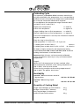
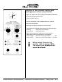
The autocast universal® 230 Casting System
A Instructions for Dental Use
B Operating Instructions for the autocast universal® 230
Casting Unit
C Accessories and spare parts
autocast universal® 230 Casting System
Index
Stand 1. 9. 03
The autocast universal® 230 Casting
System from
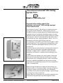
General information about the
autocast universal® 230 casting concept
from Dentaurum
The autocast universal® 230 casting unit combines the for
many years proven rematitan® casting system with the
feasibility to cover the entire spectrum of castable dental alloys.
Especially titanium’s attributes have been taken into consideration in order to guarantee the highest quality for casting.
Pure titanium, which is sold under the trade name Tritan®
or rematitan® M, with a purity grade of > 99.5%. This is in
accordance with DIN 17580 for pure titanium.
The especially strong affinity of titanium to oxygen is taken
into consideration in the melting and casting process with
the from Dentaurum developed autocast universal® 230
casting unit.
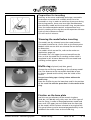
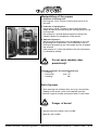
In the casting unit, pure titanium is melted with an electric
arc by means of evacuation and argon flooding of the
chamber. A copper mold is used for a melting crucible,
therefore, the titanium is melted without reacting to the
crucible.
At the end of the melting cycle, the crucible is tilted and
the titanium flows down into the muffle which is made
of rematitan® plus, rematitan® Ultra or Trinell® investment
materials, especially developed for the titanium casting
technique. An outstanding accuracy of fit for all prosthetic
work is accomplished.
When casting non-precious or precious metal alloys, the
melting is done in a ceramic crucible. Contrary to titanium
casting, the output and melting times are individually
controlled. The touch/control panel enables a quick change
in casting from alloys to titanium.
Please follow the instructions very carefully. Especially with
titanium casting, deviations can have negative effects.
autocast universal® 230 Casting System
General informations
Stand 1. 9. 03
Casting System
Instructions
for Dental Use
A Instructions for the use in Prosthetics
1. Crowns and Bridges made of Titanium
1.1 Working with rematitan® Plus Investment Material
Preparation
Fitting: Crown and Bridge Technique
Spruing System – Single Crowns / Inlays
Bridges
Muffle System
Wax-Up
Wax: Reducing Tension
Investing
Expansion control for Crowns / Bridges
Preheating Crowns / Bridges
A
A
A
A
A
A
A
A
A
A
A
1
1
1
1
1
2
2
2
2-3
4
4
1.2 Working with rematitan® Ultra Investment Material
Safety Notes
Storage
Modelling
Ring- making
Making the Casting Ring / Investment System
Fleece Lining
Wax: Tension Reducing
Mixing Ratio
Mixing
Processing Time
Setting Time
Trimming
Grinding
Waiting Time
Preheating Cycle
Availability
Quantity of Casting Metal
A
A
A
A
A
A
A
A
A
A
A
A
A
A
A
A
A
A
5
5
5
5
6
6
6
6
6
7
7
7
7
7
7
8
8
8
1.3 Working with Trinell Investment Material
Storage
Modelling
Casting Rings
Fleece Inserts
Position of Objects in the Casting Ring
Mixing Ratio
Safety Information
Mixing
Microwave Drying
Processing
Preheating Cycle – Alternatives
Night Preheating – With or Without Microwave Drying
Weekend Operation
A
A
A
A
A
A
A
A
A
A
A
A
A
A
autocast universal® 230 Casting System
Index
9
9
9
9
9
9
9
9
10
10 - 11
10
11
11
12
Stand 1. 9. 03
Reduced Speed Operation with Microwave Drying
Complete Speed Operation with Microwave Drying
Availability
A 12
A 12
A 13
Model casting made of Titanium
Preparation
Duplication with rematitan® investment
Setting time
Drying the model
Recommended waxing
Use of rematitan ® M-(Ti4)-casting metal
Sprue formers for model casting
Positioning of funnel former
Preparation for investing
Trimming the model before investing
Muffle ring
Fixation on the base plate
Investing
Preheating
Preheating oven
Preheating the muffle
Amount of rematitan® casting metal required per casting
A
A
A
A
A
A
A
A
A
A
A
A
A
A
A
A
A
A
14
14
14
15
15
15 - 16
17
18
18
19
19
19
19
20
20
20
20
21
I Conical crowns
1. Preparation
2. Duplication
3. Producing the duplicate model
4. Setting time
5. Drying the model
6. Recommended waxing
7. Spruing system
8. Preparation for investing
9. Muffle ring
10. Investing
11. Standing times, holding times, temperatures
A
A
A
A
A
A
A
A
A
A
A
22
22
22
22
22
22
23
23
23
23
23
II Telescopic crowns
1. Preparation
Amount of Titanium casting metal required per casting
A 24
A 24
2. Titanium one-piece casting technique
3. Trimming of titanium castings with the rematitan® finishing kit
Safety advices!
Cutting of sprues
Grinding
Preparation for ceramic bonding
Rubber polishing
Acid treatment
Polishing
autocast universal® 230 Casting System
A
A
A
A
A
A
A
Index
25
25
25
25
25
25
26
Stand 1. 9. 03
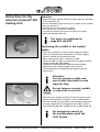
Finishing of titanium casting with the rematitan ® finishing kit
Note on safety
Description
General Notes
Preliminary operation
Procedure for finishing titanium
A
A
A
A
A
A
27
27
27
27
27
28
A
A
A
A
A
A
A
A
A
29
29
29
30
30
30
31
31 - 32
32
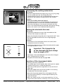
4. Casting with Alloys
Preparing the casting ring
Sprue formers
Preheating the muffle
Ceramic seal
Ceramic crucible and crucible electrode
Melting electrode
Melting process
Recognizing the point of casting
Cleaning
5. Information Service by Telephone
autocast universal® 230 Casting System
A 32
Index
Stand 1. 9. 03
A
Crowns and Bridges made of Titanium
1. Working with rematitan® Plus Investment
Material
Preparation
Waxing of crowns and bridges can be done with the usual
materials.
Crowns and bridges are waxed up in the usual way.
Minimum wall thickness 0,4 mm.
Fitting: Crown and Bridge Technique
B
Hints for wax up:
If thermoformed plastic copings are used, it is
advisable to remove the shortened spacer foil from
the plastic coping just before investing.
If a spacer is used, this should be applied somewhat more thickly in occlusal and incisal region of
the stone dies (approx. 0.1 mm). Remove the spacer
from the stone dies before fitting the cast.
The quality of the titanium casting depends, amongst
other things, on the correct choice of sprues and their
positioning.
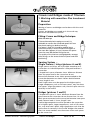
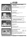
Spruing System –
Single Crowns / Inlays (pictures A and B)
C
Single crowns and inlays are in principle waxed-up on a
runner bar. An individual pattern is also positioned on a
runner bar.
T-shaped main sprue, diameter 4 mm. Minimum distance
from the sprue cone to the runner bar 10 mm.
Runner bar diameter 4 mm. Main sprue attached to the
runner bar between two leads. Pattern leads diameter
3 mm, length 3 mm.
Each single crown must be sprued at the highest point.
Larger components, such as full-cast crowns, may also have
two sprues. Align the patterns such, that the sprue cone sits
centrally in the muffle.
Bridges (pictures C and D)
D
autocast universal® 230 Casting System
T-shaped main sprue 4 mm. Minimum distance from the
sprue cone to the runner bar 10 mm. Runner bar 4 mm.
Main sprue connected to the runner bar between two sprue
leads. Pattern leads 3 mm, length 3 mm.
Each bridge component must be sprued to the runner bar
at its highest point. Larger components, such as full crowns
etc., may also have 2 leads. Align the patterns such that the
sprue cone sits centrally in the muffle. Bridges that extend
over 8 or more members must have two 4 mm main sprues
to the runner bar.
Crowns and bridges
Stand 1. 9. 03
A 1
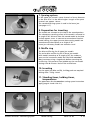
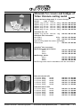
Muffle System
To avoid gas entrapment during casting, the sprue cone
must be of a certain shape. Use only the muffle bases
belonging to the system with sprue formers.
Muffle base with sprue former:
Size 3
1 piece
Ord.-No. 106-850-01
Size 6
1 piece
Ord.-No. 106-851-01
Size 9
1 piece
Ord.-No. 106-852-01
The base plate must be completely clean.
Distance between wax frame and investment surface:
max. 6 mm.
Wax-Up
To achieve a clean and rapid melt flow, joints of the sprue
cone and onto the pattern should be smooth and round.
Align the pattern horizontally.
Keep the distance from the edge of the muffle approx. 6 mm.
The pattern should lie with its upper edge 6 mm below the
edge of the muffle rings. Consequently the length of the
main supply sprue will be 15 –20 mm.
Wax: Reducing Tension
Before pressing the silicone rings over the base plate spray
the wax patterns with Lubrofilm® (Ord.-No.112-050-00) and
blow dry.
Muffle rings, flexible
Size 3
1 piece
Ord.-No. 106-840-00
Size 6
1 piece
Ord.-No. 106-841-00
Size 9
1 piece
Ord.-No. 106-842-00
Use the muffle rings corresponding to the size of the muffle
base.
Investing
In order to obtain perfect fitting castings, the handling
instructions for rematitan® Plus investment must be strictly
followed.
Required amount of rematitan® Plus investment:
For muffle size 3
1 x 250 g
For muffle size 6
2 x 250 g
For muffle size 9
3 x 250 g
rematitan® Plus investment should only be mixed with the
special mixing liquid Ord.-no. 107-602-00.
Store the mixing liquid in the refrigerator at about 8 –10°C /
46 – 50°F (not in the freezer compartment).
If outside temperature is high, powder should be cooled
also. Working time approx. 3 minutes 15 seconds at about
23°C /73°F.
autocast universal® 230 Casting System
Crowns and bridges
Stand 1. 9. 03
A 2
Mixing ratio: 250 g powder : 40 ml mixing liquid.
Mixing time in the vacuum mixer: 60 seconds.
Fill the muffle to the top with investment. Remove from the
vibrator immediately. Setting time: 40 minutes.
Pull off from the base/sprue former by twisting and grind
the side opposite the sprue, with the dry trimmer.
This promotes gas permeability of the investement in the
flow-direction of the titanium. Place the muffle with the
opening downwards in the cold oven.
autocast universal® 230 Casting System
Crowns and bridges
Stand 1. 9. 03
A 3
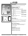
Expansion control for Crowns/Bridges
The adjustment of the expansion for the rematitan® plus
investment is exclusively done by dilution of the mixing
liquid. (see chart below).
Attention!
The mixing liquid is a concentrate which normally must be
diluted:
Recommendation for dilution:
Crowns and bridges:
60% = 6 parts of liquid + 4 parts of distilled water.
Conical and telescopic crowns:
70–100% = dilution related to the desired friction and ways
of processing.
Overall expansion
Test temperature 430°C
Setting/ thermal expansion
Setting expansion
Thermal expansion
Burnout schedule for rematitan® Plus investment
Heating rate: 5°C /41°F per min.
x = Holding times at:
150 °C / 302 °F = 90 min.
250 °C / 482°F = 90 min.
1000 °C / 1832°F = 60 min.
Preheating Crowns /Bridges
To achieve optimum expansion values and stable muffles,
we recommend 3–4 side-heated circulating air ovens with
program control (4 soaking stages) and temperature control
(5°C/41°F per min), e.g. Protherm circulating air preheating
oven (Ord.-No. 096-180-00).
There is a risk of cracking of the muffle if the oven does not
have sufficient insulation and the heating/cooling time is too
short. Do not fill the muffle space to capacity.
Overnight operation is recommended.
Holding times:
150 °C / 302 °F
90 minutes
250 °C / 482 °F
90 minutes
1000 °C / 1832 °F
60 minutes
Slow reduction of temperature to 430°C / 806°F = casting
temperature. Avoid temperature shock. Do not hold at final
temperature of 430°C / 806°F longer than 120 minutes.
autocast universal® 230 Casting System
Crowns and bridges
Stand 1. 9. 03
A 4
1.2 Working with rematitan® Ultra
Investment Material
Important! The expansion of this investment material
cannot be controlled by the mixing liquid.
Never dilute the liquid with water.
The expansion of the material is controlled by the
temperature setting of the oven.
Safety note
Danger
Mixing liquid:
If the liquid should contact the eyes,
rinse thoroughly with water and if
necessary seek medical attention.
Availability
rematitan® Ultra Powder
7 kg
rematitan® Ultra mixing liquid
1 litre
Ord.-No. 107-650-00
Ord.-No. 107-651-00
Storage
Both the powder and the mixing liquid should be stored in
the dark at room temperature.
Do not cool!
Modelling
Use only waxes or resins that leave absolutely no residue.
autocast universal® 230 Casting System
Crowns and bridges
Stand 1. 9. 03
A 5
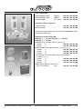
Ring-making
The investment material must be used with metal rings.
Making the Casting Ring /
Investment System
A
B
C
D
Application: crown and bridge
Ring size = 48 mm, Ring size = 65 mm
A Muffle rings, stainless steel, 2 sizes (, )
1 piece Ord.-No. 106-801-00
1 piece Ord.-No. 106-802-00
B Muffle base with sprue former, 2 sizes (, )
1 piece Ord.-No. 106-850-50
1 piece
Ord.-No. 106-851-00
C Fixing ring for connecting muffle ring and base,
2 sizes (, )
1 piece
Ord.-No. 106-845-00
1 piece
Ord.-No. 106-846-00
®
D Kera-Vlies . Asbestos free liner.
Size: 1,0 x 50 mm
25 m
Ord.-No. 127-250-00
Fleece lining
Use one dry fleece lining.
Kera-Vlies® (fleece-like ceramic material)
Ord.-No. 127-250-00
Important! It is recommended to shorten the fleece lining
to ensure that the investment material is held at the top and
bottom by the ring.
Wax: Tension Reducing
It is recommended to use a tension reducing agent such as
Lubrofilm® Order No. 112-050-00 for easier investing.
Blow dry thoroughly!
Mixing Ratio
100 g powder : 14 ml mixing liquid
Quantity required for size 3 ring,
250 g powder : 35 ml mixing liquid
Quantity required for size 6 ring,
450 g powder : 63 ml mixing liquid
autocast universal® 230 Casting System
Crowns and bridges
Stand 1. 9. 03
A 6
Mixing
Important!
Use only clean, dry mixing bowls and measuring beakers!
Always keep mixing bowls and measuring beakers away
from other investment materials!
After mixing powder and liquid, mix the compound well
by hand.
Mixing time in vacuum mixer:
Minimum 60 secs. Recommended 120 secs.
Processing Time
Approx. 6 minutes.
Setting Time / Trimming
11/ 2 - 2 hours, depending on room temperature.
Grinding
Grinding/sanding the ring surface improves its thermal
stability.
Waiting Time
rematitan® Ultra investment material is sensitive to dryness.
Therefore, it should not be allowed to stand for too long
(recommended: less than 5 min.) and should be placed in a
cold oven.
If longer holding times cannot be avoided, protect the ring
from drying out by placing it in a plastic bag or sealing it
with wax.
autocast universal® 230 Casting System
Crowns and bridges
Stand 1. 9. 03
A 7
Preheating Cycle
The expansion of rematitan® Ultra investment material con
only be controlled by the temperature. As it is not possible to
calibrate all ovens accurately, the temperature recommended
by us may be increased or decreased as required.
In our experience the temperature range is between 880°C
und 910°C/1,616°F and 1,670°F.
Higher final temperature
Lower final temperatur
=> wider fit
=> tighter fit
Longer holding time at final temperature => wider fit
Shorter holding time at final temperature => tighter fit
If the final temperature is too low, the investment material
may be unstable.
Place the ring in the cold oven.
Heat-up speed 3 – 5 °C /min / 37 °F – 47 °F per min.
1. Holding time at 250 °C /482 °F
2. Holding time at 880 – 910 °C /1,616 – 1,670 °F
90 mins.
10 – 40 mins.
To obtain a highly accurate fit, the temperature setting
should be between 880°C /616°F und 910°C /670 °F and the
holding time between 10 and 40 minutes.
Important: Not all ovens can be accurately calibrated.
It may therefore be necessary to vary our recommended
temperature.
Stage 3:
When the final temperature has been reached, allow
the temperature to decline to the casting temperture of
430 °C / 806 °F with the oven closed.
Allow the ring to adjust to the casting temperature of
430 °C / 806 °F for approx. 30 minutes.
Availability
rematitan® Ultra investement material
7 kg container
Ord.-No. 107-650-00
rematitan® Ultra mixing liquid
1 litre
Ord.-No. 107-651-00
Quantity of Casting Metal
Single crowns/bridges up to 6 elements
Bridges of more than 7 elements
Very large bridges (14 elements) /
extensive supra constructions
autocast universal® 230 Casting System
Crowns and bridges
22 g
31 g
36 g
Stand 1. 9. 03
A 8
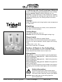
1.3 Working with Trinell Investment Material
Trinell is the result of ongoing development of our already
proven rematitan® Ultra Investment Material for the
rematitan® Casting Technique. Trinell, besides the standard
work, will expedite the working cycle significantly. With the
appropriate casting unit, the casting surfaces are almost
oxide-free.
Storage:
Please store powder and mixing liquid at room temperature
in a dark area.
Modelling:
Use only residue-free burn-out waxes, such as (Dentaurum
Star Wax), or similar products.
Casting Rings:
Use metal casting rings, size 3 – 9.
Attention: Do not use old and damaged casting rings.
Fleece Inserts:
Use only dry, elastic fleece (no paper fleece).
Shorten fleece so that investment material rests approximately 5 mm, top and bottom, directly against the casting
ring.
1 fleece insert 1 mm – dry –
(Kera Vlies® Order No. 127-250-00)
Position of Objects in the Casting Ring:
Cover with approximately 8 mm of investment material.
Outer distance from fleece insert at least 5 mm.
Mixing Ratio:
100 g powder : 14 ml mixing liquid or special speed liquid
Size 3 casting ring – 250 g powder: 35 ml mixing liquid or
special speed liquid
Size 6 casting ring – 500 g powder: 70 ml mixing liquid or
special speed liquid
Size 9 casting ring – 750 g powder: 105 ml mixing liquid or
special speed liquid
Left over investment material can be stored in the original
packaging, but should be closed tightly with the enclosed
clip.
Safety Information:
Danger
Should mixing liquid or special speed-liquid
come in contact with the eyes, rinse thoroughly
with water, and if necessary, contact your doctor.
Attention: Never add water to the mixing liquid or
special speed liquid.
autocast universal® 230 Casting System
Crowns and bridges
Stand 1. 9. 03
A 9
Mixing:
Always use clean and dry mixing and measuring utensils!
Attention: Use one particular measuring container only for
Trinell liquids.
Mix well manually!
Mixing time in a vacuum mixing unit: 60 seconds
Attention: Do not dilute the slightly thick material.
Due to the moisture content, and the timely processing
time, a bubble-free investment is guaranteed.
Working Time: Approximately 6 minutes
Setting Time: 60 minutes
Microwave Drying:
The special feature of this investment material is that it can
be dried in a microwave oven. Due to this drying process,
the texture of the investment material is greatly improved.
General Information with Reference to the Microwave:
Investment casting rings with metal casting rings can be
dried in a suitable microwave oven at a low setting.
The best results are achieved when the microwave has a
turning plate and a microwave distributor that is located
on the inner side wall, with a plastic covering.
The microwave has to have continuous power starting
with "0", or the lowest setting (defrost) has to be at approximately 80 Watt. The drying time has to be reduced if the
power is above 80 Watt. The less suitable units are the ones
with an upper or lower microwave distributor.
Processing:
After investing, and one hour of setting time, cut the
surface with a knife (do not use a model trimmer).
Remove the bottom of the casting ring.
Set microwave to lowest setting (defrost).
Place casting ring, with the sprue facing down, into the
microwave. Set the unit for approximately 6 –10 minutes,
depending on size and power of the microwave.
Best results are achieved with units of 800 Watt power and
a defrost setting of 80 Watt.
Example with the setting of 80 Watt ("Defrost"):
Size 3 casting ring:
6 minutes
Size 6 casting ring:
8 minutes
Size 9 casting ring: 10 minutes
This pertains to single casting rings. With more than one, the
working times have to be adjusted between 8 and 10 minutes.
Microwave drying is necessary with speed operation.
It is recommended with night operation.
autocast universal® 230 Casting System
Crowns and bridges
Stand 1. 9. 03
A 10
Preheating Cycle – Alternatives
Attention: The end temperature of (870–900°C /
1598–1652°F) is very important for a proper fit.
Depending on oven size and calibration, the temperature may have to be adjusted, up or down.
Higher end temperature = wider fit
Lower end temperature = tighter fit
Attention: Every package of investment contains a separate
instruction sheet that gives recommendations for
end temperature and holding time, according to
that particular batch.
Night preheating with or without
microwave drying:
Attention: For night preheating, use only Trinell Mixing
Liquid!
(The Trinell Special Speed Liquid can only be
used for reduced and full speed preheating.)
In order to increase stability, we strongly recommend using the microwave!
Place the casting ring, with the sprue facing down into the
cold oven, preheat in 2 steps and cool down phase.
Preheating 1. Step (heat acceleration 4 °C / 39 °F)
250 °C / 482 °F 60 min. holding time
Preheating 2. Step (heat acceleration 4 °C / 39 °F)
870 – 900 °C / 1598 –1652 °F
20 min. holding time
(End Temperature)
Cool down 3. Step
400 °C / 752 °F 30 min.holding time
Casting Temperature:
400 °C / 752 °F
We recommend to reduce the end temperature to
approximately 10 °C/50 °F for the telescope and conical crown
technique. Additional adjustments to the expansion can be
made by extending (higher expansion) or reducing (lower
expansion) the holding time at the end temperature.
For the telescope and conical crown technique, use only
night preheating not speed preheating.
autocast universal® 230 Casting System
Crowns and bridges
Stand 1. 9. 03
A 11
Weekend Operation:
Attention: For weekend operation, use only Trinell mixing
liquid!
(Use Trinell Special Speed Liquid only for reduced
and full speed preheating.
When using overnight preheating microwave drying is
imperative as it increases ring stability.
After microwave drying, place casting, with the sprue
facing down, into the cold oven and program the oven for
preset preheating at 2 steps and cool down phase.
Complete Speed Operation with
Microwave Drying
Attention: At Speed Operation use only Trinell Special
Speed Liquid! (The Trinell Mixing Liquid should only
be used for night preheating).
In exceptional cases, the size 3 casting can be placed in the
oven at the end temperature. Slight variations in the fit
and stability are then unavoidable.
After microwave drying and a 5 minute resting phase, place
casting in the horizontal position in the 870 – 900 °C / 1598
– 1652 °F / 20 min. holding time preheated oven.
After completed holding time, cool off casting at 700 °C /
1292 °F in a closed oven.
At 700 °C / 1292 °F remove casting and cool at room temperature.
Casting temperature between 200 – 400 °C / 392 – 752 °F.
Reduced Speed Operation with
Microwave Drying
Attention: At reduced speed operation, use only Trinell
Special Speed Liquid! (The Trinell Mixing Liquid should
only be used for night preheating)
After microwave drying and a 5 minute resting phase, place
casting with sprue facing down into a 400 °C / 752 °F
preheated oven.
Constant preheating at maximum acceleration rate to
870 – 900 °C / 1598 – 1652 °F and a 20 minute holding time.
Cool Down Variations:
1. Cool down casting at 400 °C / 752 °F with oven closed
2. Cool down casting at 700 °C / 1292 °F thereafter at
400 °C / 752 °F with opened door
3. Transfer castings after cool down of 700 °C / 1292 °F
into a preheated oven of 400 °C / 752 °F.
autocast universal® 230 Casting System
Crowns and bridges
Stand 1. 9. 03
A 12
Availability:
Trinell Special Speed Liquid 1000 ml
Ord.-No. 107-655-00
Trinell Mixing Liquid
1000 ml
Ord.-No. 107-653-00
Trinell Investment Material 28 x 250 g Ord.-No. 107-654-00
autocast universal® 230 Casting System
Crowns and bridges
Stand 1. 9. 03
A 13
Model casting made of Titanium
Preparation
The reactive layer, also called the „alpha case“, formed at
the contact zone between the rematitan® casting metal
and the investment should be kept as thin as possible.
Because of the special properties of titanium, such as low
specific gravity, high melting point, low contraction and
very high affinity for oxygen, all the factors which influence
titanium must be dealt with differently than with conventional dental castings.
This includes all the materials and operations intended
specifically for the autocast universal® 230 casting unit.
Other materials may have an adverse affect on the casting
results.
Duplication with rematitan® investment
After appropriate preparation, the master model is
duplicated with Rema®-Sil silicone (Ord.-No. 108-700-00 /
108-701-00, see processing instructions).
15 mm
Note! Minimum thickness of the refractory at the deepest
part of the palate is 15 mm. If necessary, increase
the height of the master model with gumex before
duplication. Higher models may be trimmed down
to 15 mm.
In the case of split cast models etc., the investment model
should be trimmed down to proper size before investing.
After removal of the master model, the silicone mould is
degreased with Lubrofilm®. Blow dry immediately.
No sprue former is necessary. Casting is done from the top.
Shake the mixing liquid well before use.
rematitan® Plus is mixed with rematitan® mixing liquid in
a ratio of 250 g : 40 ml in a vacuum mixer (Airvac, Ord.-No.
095-060 -00 / 095-070-00) for 60 seconds and the mixture is
poured into the silicone mould.
Working time at 23 °C/ 73,4 °F: 2 minutes 45 seconds.
A longer working time can be achieved by cooling the
mixing liquid.
Note! Due to the high specific gravity of rematitan® Plus
investment, heavy particles of the investment may be
deposited in the mixing beakers after the mixing operation.
After mixing in the Airvac, the investment is briefly mixed
manually using a spatula (only for 250 g).
The surface of the investment must be smooth.
autocast universal® 230 Casting System
Model casting
Stand 1. 9. 03
A 14
Setting time
Setting time is 40 minutes. Refractory should not be placed
in a pressure pot while setting.
Drying the model
70 °C/158 °F, for 40 minutes in a circulating air drying cabinet.
Note! Do not use higher temperatures, since this will
affect the surface smoothness.
Risk of damage to the surface (pasty).
If the model is dried in the preheating oven, check the
temperature and adjust if necessary.
Models with too high a moisture content prevent good
attachement of the wax or plastic patterns.
The environmentally compatible cold hardener Ökodur
(Ord.-No. 167-300-00) is used as model hardener.
After 40 minutes at 70°C/158°F in the drying cabinet, the
thoroughly dried duplicate model is immersed in the cold
Ökodur hardener liquid for 5-10 seconds. The hardened
model is then subsequently dried for 5-10 minutes in a
drying cabinet at 70 °C / 158 °F.
The dried, hardened model should be waxed and invested
within 6 hours. If it stands for longer, the model surface
may absorb moisture from the atmosphere and become
soft. The original hardness of the model can be achieved
by returning it to the drying cabinet and drying it again
(70 °C / 158 °F, 10 min).
Recommended waxing
If rematitan® casting metal is used for model casting,
the construction of the framework should have thicker
dimensions because of the different physical values
compared to that to CoCr alloys.
Full palate:
Horseshoe:
Anterior-posterior palatal bar:
Palatal strap:
thickness
thickness
thickness
thickness
0,8
0,8 – 1,0
0,8 – 1,0
0,8 – 1,0
mm
mm
mm
mm
Additionally reinforce lower jaw lingual bars 4.3 x 2.3 mm
(Ord.-No. 111-113-00).
All the figures are recommendations. Stabilization can also be
achieved by waxing-in reinforcements.
The wax and plastic patterns used should be suitable for
titanium casting.
Note! Do not use alien adhesives. To guarantee that the
titanium melt flows properly into the mould,
be sure the wax /plastic surface is smooth and clean.
autocast universal® 230 Casting System
Model casting
Stand 1. 9. 03
A 15
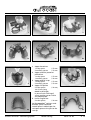
1
2
3
1a
2a
3a
4
4a
1 Upper horseshoe
1 main sprue
5 mm
2 auxiliary sprues
3 mm
2 Upper anterior-posterior
palatal bar
1 main sprue
5 mm
1 auxiliary sprue
4 mm
3 Upper palatal strap
1 main sprue
5 mm
2 auxiliary sprues
3 mm
4 Upper full palate
2 main sprues
4 mm,
10–15 mm long
Model at 45°angle.
In case of resin relining of
a-line, position sprues within
the palatal plate.
5 Lower lingual bar
2 main sprues
4 mm
®
1a-5a rematitan castings sandblasted, sprues removed.
Attach sprues in delta shape. Do
not taper sprues at the joint to the
wax up.
autocast universal® 230 Casting System
Model casting
5
5a
Stand 1. 9. 03
A 16
Use of
rematitan® M-(Ti4)-casting metal
rematitan® M has a higher elongation limit, tensile strength
and modulus of elasticity values.
rematitan® M has slightly poorer flow properties than the
more commonly used titanium Ti1. However, it is easier to
cast than is normally the case when using titanium grade 4.
Slight modification of the casting sprues allow the
fabrication of very delicate partial dentures.
Casting sprues:
With very delicate model casting structures, 3 or 4 sprues,
with a diameter of 3, 4 or 5 mm, are joined to the wax-up
from below in the form of a star.
Example: Maxillary partial framework.
4 mm
3 mm
3mm
5 mm
autocast universal® 230 Casting System
Model casting
Stand 1. 9. 03
A 17
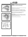
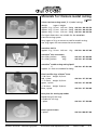
Sprue /sprue former
All model castings are cast from the top.
Sprue formers for model casting
Plastic sprue cones should be used.
Note! Do not use other cone shapes than recommended.
The shape of the sprue cone and the position of the sprue
channel help the melt to flow cleanly. The funnel must be
in the center of the casting ring, so that the muffle can be
centered cleanly in the unit.
Attention! The new funnels are equipped with cavity
formers for better aligning of the packing rings.
B
A
C
A Correct positioning, B + C Incorrect positioning.
Not centered (B) or inclined sprue cone positions (C)
adversely affect the way the melt flows into the hollow
cavity of the casting.
C Reduced seal coverage and uneven pressure on the
muffle.
Positioning of funnel former
Wax up funnel with bottom edge at occlusion level.
The investment must be filled to the top edge of the funnel
former. Avoid air bubbles at the fitting surface.
autocast universal® 230 Casting System
Model casting
Stand 1. 9. 03
A 18
Preparation for investing
Contrary to the crown and bridge technique, removable
restorations are made with a model which has to be
invested in a ring. In order to avoid loss of pressure during
the casting process, there must be a tight bond between
the refractory model and the investment ring. Any deviation
form the recommended materials and procedures may
result in cracking of the ring due to the expansion characteristics of the investment material.
This will result in miscasts.
Trimming the model before investing
The models are dry trimmed up to the waxed patterns.
The model should be 10 –15 mm thick at the lowest point.
Models which are too thick are trimmed flat on the base
to dimensions.
For models which are too flat, refer to the section on
duplication, page A 9 .
The models for a full upper jaw are trimmed from the
front so that the model has a standing surface which is
angulated at 45°. Distance between the wax model and
standing surface approx. 4 mm.
Muffle ring
of plastic (red, blue, green)
Choose the muffle ring according to the refractory model
size. The distance to the wax model should be at least
8 –10 mm. Spread vaseline thinly over the inside of the
muffle.
Do not insert lining tape. Casting is done without the
muffle ring.
Place the muffle ring on the base plate and fix the position
of the model. Be sure the sprue cone is in the center of the
ring.
Fixation on the base plate
Seal the wax up refractory to the smooth ring base
(Ord.-No. 127-309-00) using sticky wax. Use a thin layer of
wax for fixing, in order to keep gap between model and
coat small. Full upper jaws are waxed onto the front side
of the model, which has been trimmed at an angle of 45°.
The sprue former must be centered perpendicularly in the
middle of the muffle. Press on the muffle ring.
autocast universal® 230 Casting System
Model casting
Stand 1. 9. 03
A 19
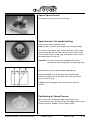
Investing
For one muffle 2 x 250 g packs of rematitan® Plus investment
(Ord.-No. 107-600-00) are required.
Mixing ratio = 500 g : 80 ml.
Shake rematitan® mixing liquid (Ord.-No. 107-601-00) before
use.
For small models and a red muffle ring, and generally for
blue muffle rings, 3 x 250 g packs are used.
Mixing ratio: 250 g : 40 ml liquid.
Note:
Process rematitan® Plus investment at 18 –22 °C / 64,5 –72 °F.
Cool the liquid in a refrigerator a 8 –10 °C / 46,4 – 50 °F if
necessary (not in the freezer compartment). If outside
temperatures are very high, also cool the powder.
Mix the rematitan® Plus investment and liquid in a vacuum
mixer for 60 seconds. Use a separate mixing beaker.
Fill the muffle to 1 mm below the edge of the sprue former.
Be sure that the surface is smooth and without bubbles.
For full upper jaws models waxed-up at an angle of 45°, brush
the undercut areas of the investment model with rematitan®
Plus investment using a large brush, before mounting the
muffle ring. This prevents from undesired bubbles in the wax
up.
Setting time 40 minutes. Remove muffle from base and ring.
Break investment at the outer muffle edges A.
Bevel the sprue cone edge B to ensure a flat surface for the
seal.
C
A
B
Note C:
Do not trimm the surface with a model trimmer.
Preheating
Place investment mold in the oven with the sprue opening
facing down.
Be sure the base of the oven is clean.
Preheating oven
The oven should be equipped with a 3- to 4-sided heating
chamber and well-insulated (e. g. Protherm preheating
oven, Ord.-No. 096-170-00 and 096-180-00).
Required end temperature 1000 °C / 1832 °F.
A programmable furnace is imperative. Circulating air
is advisable. Do not fill the oven to its capacity.
Furnaces without sufficient insulation or where the
temperature increase decrease rate is too high may cause
mould cracking.
autocast universal® 230 Casting System
Model casting
Stand 1. 9. 03
A 20
Preheating the muffle
Heating rate: 5 °C / 41°F per minute.
150 °C 90 min. -> 250 °C 90 min. -> 1000 °C
302 °F 90 min. -> 482 °F 90 min. -> 1832 °F
60 min.
60 min.
Cooling rate: 5 °C / 41°F per minute. Slow cooling to
430 °C / 806 °F = remove muffle. Avoid temperature shock.
Holding time at end temperature 430 °C / 806 °F not longer
than 120 minutes.
Amount of rematitan® casting metal
required per casting
Normal framework casting
Frameworks of large dimension
autocast universal® 230 Casting System
Model casting
31 g
36 g
Stand 1. 9. 03
A 21
2. Titanium one-piece casting
technique
One-piece casting for crowns of 2° and 4° taper is possible
with the following procedure.
Telescopic crowns are dealt with separately in section II.
I Conical crowns
1. Preparation
Wax up primary crowns on the master model.
Angulation (tapering) 2° or 4°.
2. Duplication
Duplicate the master model with the primary crowns using
Rema®-Sil silicone (Ord.-No. 108-700-00 / 108-701-00).
3. Producing the duplicate model from
rematitan® Plus investment
Degrease the negative silicone mould with Lubrofilm®
(Ord.-No. 112-050-00).
Mix rematitan® Plus investment (Ord.-No. 107-600-00) and
rematitan® model casting mixing liquid (Ord.-No. 107-601-00)
in a ratio of 250 g : 40 ml and fill the silicone mould.
4. Setting time
40 minutes.
5. Drying the model
70 °C / 158 °F, 40 minutes
Harden the model with Ökodur cold hardener (see page A 15)
6. Recommended waxing
Upper jaw horse shoe
thickness 1 mm
Upper jaw skeletal plate
thickness 1 mm
Upper jaw transversal bar
thickness 1 mm
Additionally reinforce lower jaw lingual bars.
To ensure complete casting of secondary crowns the
minor connectors must be waxed thicker.
● Waxing thickness of the secondary crowns not less than
0,5 mm.
●
autocast universal® 230 Casting System
Model casting
Stand 1. 9. 03
A 22
7. Spruing system
In the upper jaw, attach 2 sprue channels of 4 mm diameter
in the form of a v in the dorsal region. Length of the sprue
channels are approx. 10 mm.
The standard spruing system is used in the lower jaw.
(see page A 11)
8. Preparation for investing
The models are trimmed on the side to the waxed portions.
The subsequent standing surface of the model is trimmed at
an angle of 45°. Distance from the waxed model to the base
surface approx. 4 mm. In contrast to conventional titanium
model casting, the upper jaw one-piece casting models are
waxed onto the base plate at an angle of 45°.
Lower jaw refractory models are waxed as usual.
9. Muffle ring
The blue muffle ring for all upper jaw models.
The red or blue muffle ring for all lower jaw models.
With models waxed-up at an angle of 45°, the undercut
areas on the investment model are filled with rematitan®
Plus investment using a large brush before mounting the
muffle ring. This prevents from bubbles on the wax model.
Setting time 40 minutes. Peel off the muffle base.
10. Investing
For the upper jaw (blue muffle), 3 x 250 g packs are required.
Mixing ratio = 750 g : 120 ml.
11. Standing times, holding times,
temperatures
The parameters for the rematitan® casting system instructions
apply (page A 4 and A 20–21).
autocast universal® 230 Casting System
Model casting
Stand 1. 9. 03
A 23
II Telescopic crowns
Preparation
1. The tooth arch in the silicone mould is first filled with
rematitan® Plus investment, which is mixed with diluted
rematitan® Plus crown/bridge mixing liquid (Ord.-No.
107-602-00).
Attention!
The mixing liquid is a concentrate which normally must
be diluted:
Recommendation for dilution:
Crowns and bridges:
60% = 6 parts of liquid + 4 parts of distilled water.
Conical and telescopic crowns:
70–100% = dilution related to the desired friction and
ways of processing.
2. Before the investment has set, the mould must be filled
with rematitan® Plus investment in the normal consistency
of 250 g : 40 ml (partial denture mixing liquid,
Ord.-No. 107-601-00).
3. The subsequent operating steps are the same as sections
4. to 11. of the instructions for conical crowns.
Amount of Titanium casting metal
required per casting
Minor combination work
Extensive combination work
autocast universal® 230 Casting System
Model casting
31 g
36 g
Stand 1. 9. 03
A 24
3. Finishing of titanium castings
Safety advices!
Danger
Abraded or separated titanium particles when
hot react with oxygen and produce sparks.
Caution: Risk of combustion and explosion.
Cool the workpiece with water.
If suction lines are used, change the filter paper
regularly. Warning: Otherwise fire hazard.
Warning! Always use trimming materials only for
processing titanium. Keep separate!
Cutting of sprues
Warning! Do not overheat the casting when separating.
Cool. No red heat.
For recommended separating discs, see page C 6.
Grinding
If possible, use carbide burs and trim in one direction.
Tungsten carbide burs are particularly suitable (see page C 6).
Grinding points can be used for smoothing surfaces
(see page C 6).
Note! Use carbide burs and grinding points only for
trimming rematitan®. Keep separate!
Preparation for ceramic bonding
Surfaces which are to be blended with ceramic must be
finished entirely with carbide burs. The amount of material
removed depends on the particular material thickness.
Afterwards, blast off the framework surface with aluminum
oxide and condition according to the ceramic manufacturer’s
instructions.
Rubber polishing
When rubber polishing, it is essential to avoid severe
heating of the polishing surfaces!
(For recommended rubber polishers, see page C 6.)
Uniform smoothing of the metal surface to be polished is
achieved if this has been ground with very fine emery paper
(500 –1000 grain) in a sandpaper holder.
Acid treatment
Do not place titanium castings in hydrofluoric acid.
Titanium is quickly damaged by hydrofluoric acid!
autocast universal® 230 Casting System
Model casting
Stand 1. 9. 03
A 25
Polishing
Polish and shine with a soft polishing brush and special
titanium polishing paste (Tiger brillant, Ord.-No. 190-350-00,
see page C 6 –7).
Note! To form a passivity layer, leave polished work
exposed to air for at least 10 minutes.
Only then steam clean or use ultrasonic cleaner.
autocast universal® 230 Casting System
Model casting
Stand 1. 9. 03
A 26
Trimming of titanium castings with
the rematitan® finishing kit
Note on safety
– Always wear safety goggles when finishing
castings.
– Always turn on the extractor unit during work.
– The maximum rotation speeds of the various
instruments must not be exceeded
Description
Pure titanium is a soft tough material which requires special procedures for finishing and polishing. The Finishing Set
(Ord.-No. 135-500-00) contains the most important materials
for the efficient finishing and polishing of titanium for dental
purposes.
The sequence of use and the most important finishing
characteristics of the individual instruments are described
below.
General Notes
– Use the finishing materials for titanium only
– The grinding tools must not become clogged.
This precludes the use of other types of tool
(e. g. diamonds) for finishing purposes.
– In addition, local overheating of the workpiece must be
avoided. For this reason, care must be taken when using
rubber polishers.
– Do not exert too much pressure and work at low speeds.
Preliminary operation
Titanium castings are always covered by an oxide skin
which must be removed carefully before work begins.
This is done with the blasting unit and blasting medium
of various grades.
Note: Sparks are always created when finishing titanium.
When using rematitan® Plus investment material:
Model casting:
blasting type Al 2O3 blast (< 250 µm)
Crowns and bridges:
blasting type Al 2O3 blast (< 125 µm)
Important: Do not damage the edges of the crown.
Do not exert too much pressure.
autocast universal® 230 Casting System
Accessories and replacement parts
Stand 1. 9. 03
A 27
When using rematitan® ultra investment material:
Use Aluminium oxide Al 2O3 (30 µm – 250 µm)
For very fine parts (inlays) careful blasting with polishing
beads is sufficient.
Procedure for finishing titanium
Follow the finishing instructions in the correct sequence.
This enables you to achieve an excellent polish on the
titanium with very little effort and expense.
Preparation of surfaces for ceramic applications:
– use tungsten carbide burs only
– blast carefully with Al 2O3 (125 µm – 250 µm) and
2–3 bars of pressure.
Important: After polishing, the workpiece must be allowed
to passivate in the atmosphere for 10 minutes before
cleaning with steam jet or ultrasonic cleaner.
In addition to the component numbers, observe the order
numbers for spare parts on page C 9.
Finishing instructions
Operation
Processing material
Remarks
ST cut-off disk (large)
STM cut-off disk (thick)
TX cut-off disk (thin)
(1)
(2)
(3)
Thick casting channels, ST cut-off disk (quick grinder) or STM
(handpiece)
Thin casting channels, TX cut-off disk
Do not tilt, cool workpiece with water
Finishing
(rough)
Tungsten
Tungsten
Tungsten
Tungsten
(4)
(5)
(6)
(7)
Maximum rotation speed 10.000 /min.
Low pressure force
Finishing
(fine)
Aloxin stone, B, blue
Aloxin stone, C, blue
(8)
(9)
Circular motion on workpiece
Do not use Aloxin stone material with surfaces for ceramic
application
Removing the
casting channels
Fine grinding
Rubber polishing
Polishing
carbide
carbide
carbide
carbide
bur,
bur,
bur,
bur,
mini
midi
maxi
maxi plus
Emery paper -500-
(10)
Recommended before rubber buffing
Rubber disk (grey)
Rubber disk (red)
Rounded rubber polisher (red)
Rubber cylinders (red)
(11)
(12)
(13)
(14)
Use sparingly without pressure and at low speeds
(do not overheat)
grey = preliminary polish, red = fine polish
(align cylinders before first use)
Polishing brush, large, (polishing motor)
Polishing brushes, black
Small brushes
Tiger brilliant, polishing paste
(15)
(16)
(17)
(18)
Change direction of polish frequently
For high lustre, no addition of polishing paste
autocast universal® 230 Casting System
Accessories and replacement parts
Stand 1. 9. 03
A 28
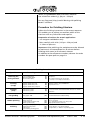
4. Casting with Alloys
All customary dental alloys for prosthetics can be cast with
the autocast universal® 230 unit. The alloys are melted on a
special ceramic crucible. The electric arc is deflected over an
electrode that is set in the crucible.
The output of the electric arc is regulated according to the
alloy being used. The tipping of the crucible is done manually
via the viewing window.
Preparing the casting ring
Prepare casting object as usual, either with a sprue bar or
directly.
The use of metal muffle rings is strongly recommended.
Depending on the investment material or preheating
program, in some cases micro cracks can form in the investment material. Cracks can lead to inferior pressure values
when casting and therefore produce a poor casting reaction.
When model casting, the stability of the casting muffle has
to be considered. If necessary, metal muffle rings can also
be used.
Sprue formers
It is essential to use sprue formers from the rematitan
casting system, or other bases with sprue formers that have
a clean and smooth base.
In order to seal the casting chamber, it is important to have
a complete and smooth seal. When model casting, it is also
recommended to use the rematitan® sprue formers (see
instructions for rematitan®).
Attention! Do not use sprue formers which do not provide
a perfect sealing (i. e. BEGO etc.).
Preheating the muffle
The muffles are preheated, independent of the casting
process, according to the instructions for the investment
material and casting alloy.
autocast universal® 230 Casting System
Accessories and replacement parts
Stand 1. 9. 03
A 29
Ceramic seal
Only high temperature ceramic seals should be used.
(Ceramic seal C – Order No. 090-012-60)
Multiple uses are only suitable when the muffle base is very
smooth. Do not reuse more than three (3) times.
Ceramic crucible and crucible electrode
Two sizes of ceramic crucibles can be used when casting
with alloys.
The small crucible Order No. 090-161-00 can be used for up
to 36 grams of non-precious metals and for up to 45 grams
of precious metal alloys.
The large crucible Order No. 090-161-50 can be used for
a maximum of 54 grams of non-precious alloys and a
maximum of 95 grams of high gold containing alloys.
Attention: Precious metal reduced alloys have a lower
specific weight, therefore, the maximum melting weight is
clearly reduced when compared to high gold containing
alloys.
Use a separate ceramic crucible for every alloy!
The crucible electrode should also only be used for one
alloy.
Repeated use of the ceramic crucible for up to 40 times is
possible, depending on the alloy being used.
The ceramic crucible cannot be cooled down in water after
casting (danger of breakage). Without cool down, the
crucible can be adjusted up to three times by using tongs
or tweezers.
The crucible electrode has to protrude slightly from the
ceramic pan. Do not sharpen the electrode! Connect the
electrode with a wrench with the copper crucible support,
and tighten.
Melting electrode
The melting electrode in the upper melting chamber
has to be well sharpened (see section B 18). The position of
the melting electrode remains the same when casting with
alloys or titanium.
The space between both electrodes is 15 mm when
casting alloys. Small differences of ± 1 mm do not have
an influence on the casting.
autocast universal® 230 Casting System
Accessories and replacement parts
Stand 1. 9. 03
A 30
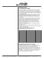
Melting process:
Controlling the output
The power output of the casting machine is controlled by
an inverter from 5% to 100% by use of a potentiometer.
The predetermined output setting does not only depend on
the melting temperature of the alloy, but also the quantity
of the casting metal.
Due to excessive cooling down of the casting muffle, the
melting time should not exceed 40 – 50 seconds. An automatic safety device tips the crucible after a maximum of
90 seconds.
The suggestions that are mentioned with reference to the
output settings, and depending on the melting amount,
represent rough guidelines. The output may deviate at
different melting temperatures. At the same time, the
condition of the melting electrode influences the performance of the electric arc.
Electrodes that become dull after many castings decrease
the performance.
If necessary, the output can be corrected either up or down
during the melting process.
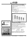
Average setting “non-precious metal”: 50%
Average setting “precious metal”: 15%
Non-precious alloys
Precious alloys
Melt Quantity
Melt Output
1 casting piece – 6 g
approx. 30–35%
up to 2 casting pieces 6 –12 g
approx. 40%
3 to 6 casting pieces 13 – 36 g
approx. 50%
7 to 8 casting pieces 37 – 48 g
approx. 55%
9 casting pieces 49 – 54 g
approx. 60–65%
up to approx. 10 g
approx. 10%
10 g – 30 g
approx. 15%
30 g – 50 g
approx. 20%
50 g – 70 g
approx. 25%
70 g – 95 g
approx. 30–35%
Recognizing the point of casting
After igniting the electric arc, the melting process can be
monitored through the darkened viewing window.
At low output settings, the second darkened window can
be pushed aside in order to improve the visual monitoring.
Attention: At a higher output > 50%, the second safety
viewing glass has to remain, otherwise eye damage may
occur due to the bright beam of light.
autocast universal® 230 Casting System
Accessories and replacement parts
Stand 1. 9. 03
A 31
The casting process is manually controlled via the “cast”
button when the melt builds a uniform mass. To avoid
partially melted ingots, place them in an overlapping
pattern and have them contact one another on the crucible.
Avoid placing the ingots in the rear area of the crucible,
they are obscured from vision behind the electric arc
a) Ensure a good contact of the metal to the crucible
electrode
b) Precious and non precious alloys must be cast immediately when the melting point has been reached without
any additional temperature soaking.
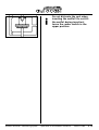
Cleaning
Melt residues and splatters have to be removed after every
casting process. Especially particles in the funnel between
both chambers.
The window of the casting chamber has to be cleaned on
a regular basis. (In order to observe the melting process).
Both chambers have to be cleaned regularly.
5. Information Service by Telephone
Contact our Prosthetics Department for any questions you
might have – Hotline +49 7231/803-410
J. P. Winkelstroeter KG
Turnstraße 31 · 75228 Ispringen
Telephone + 49 72 31/ 80 34 22
Fax + 49 72 31/ 80 34 09
autocast universal® 230 Casting System
Accessories and replacement parts
Stand 1. 9. 03
A 32
Casting Unit
Operating Instructions
for the
autocast universal® 230
Casting Unit
Index autocast universal® 230 Casting Unit
B Operating Instructions for the autocast universal® 230 Casting Unit
Instructions
B3
Correct Use
Guarantee and liability
Safety Regulations
Symbols and Warnings
Note on Instructions
References to residual risks
B3
B3
B4
B4
B5
B5
Fundamental Safety Instructions
B6
Comments on the Instructions
Responsibilities of the operator
Responsibilities of personnel
Dangers in working with the machine
Safety devices
Safety measures
Training of staff
Electrical hazards
B6
B6
B6
B7
B7
B7
B7
B8
Danger Points
B9
Modifications to the machine
Cleaning the machine, disposal of waste
B 10
B 10
Note on Maintenance
B 11–12
Maintenance, repair and troubleshooting
B 13
Information for the autocast universal® 230 Casting Unit
B 14
Casting with Titanium
B 14
Casting with Alloys
B 14
Technical data
B 15
Installation
B 16
Location
Electrical connection
Argon supply
autocast universal® 230 Casting System
B 16
B 16
B 16
Index
Stand 1. 9. 03
B 1
Instructions for the autocast universal® 230 Casting Unit
B 17
Start-Up
Positioning the crucible in the crucible holder
Positioning the melting material
Setting the electrode clearance
Location of the ring-support plate
Ceramic seal
Positioning the muffel
Initiation of the automatic melting and casting process when using titanium
Sequence while casting titanium
Manipulating of the process
End of process
Casting of alloys: Start of melt and casting process when using alloys
Additional function crucible control
Maintenance and setting
B 17
B 17
B 18
B 18
B 18
B 19
B 19
B 21
B 22
B 23
B 23
B 24
B 25–26
B 27
Inspection before every casting process
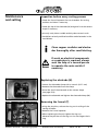
Replacing the electrode
Removing the funnel
Replacing the safety glass
Care
Weekly maintenance
B 27
B 27
B 27
B 28
B 28
B 28
Error signals – causes and remedies
B 29
Faults and remedies
Technical service
B 29
B 30
Accessories for autocast universal® 230 Casting Unit
B 31
B 31
B 31
Included with basic unit
Cleaning agents
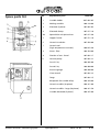
Spare parts list
B 32
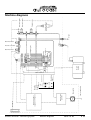
Machine diagrams
B 33
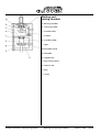
Individual elements of the autocast universal® 230
B 34
Melting and casting chamber
B 35
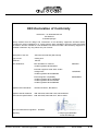
Declaration of Conformity
B 36
autocast universal® 230 Casting System
Index
Stand 1. 9. 03
B 2
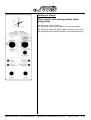
Instructions
Correct use
The autocast universal® 230 unit is intended only for melting
and casting titanium and other alloys that are used in dental
prosthetics.
It is not suitable for any other purpose.
Dentaurum cannot be held liable for any damage caused by
incorrect or improper use.
The correct use of the machine also includes:
• Full compliance with the Instructions and maintenance
procedures
Guarantee and liability
Our “General Conditions of Sale and Supply” apply in all
cases and are available to all customers. Claims for damage or
injury under the guarantee or manufacturer’s liability will not
be accepted if they are attributable to one or several of the
following causes.
• Incorrect use of the machine for other than its intended
purpose
• Incorrect installation, start-up, operation and maintenance
of the machine
• Operation of the machine with defective, incorrectly
installed or ineffective safety devices
• Non compliance with the operating instructions regarding
transport, storage, installation, start-up, operation and
maintenance of the machine
• Unauthorised modifications to the machine
• Inadequate monitoring of machine components which are
subject to wear
• Unauthorized and-or incorrect repairs
• Damage caused by foreign bodies or by Act of God.
autocast universal® 230 Casting System
Instructions for use
Stand 1. 9. 03
B 3
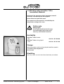
Safety Regulations
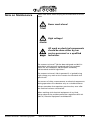
Symbols and Warnings
In these Instructions, possible sources of danger are marked
by the following symbols.
Reference to a possible source of danger to life or limb.
Danger
Disregarding these instructions may cause serious injury or
danger to health.
Reference to a potentially dangerous situation.
Attention
¡
Important
autocast universal® 230 Casting System
Disregarding these instructions may cause less serious injury
or damage to property.
This symbol gives important information on the correct
handling of the equipment.
Disregarding these instructions may cause the equipment to
malfunction or impair the working environment..
Instructions for use
Stand 1. 9. 03
B 4
Note on Instructions
In accordance with current regulations, these instructions
contain all the information necessary for safe operation of
the machine.
Apart general references to safety regulations which
guarantee safe operation of the machine when it is used
correctly, these instructions also contain:
References to residual risks
which, in view of the design and conception of the machine,
are impossible to remove. References to such residual
risks are specially marked (see section on SYMBOLS and
MARKINGS).
¡
autocast universal® 230 Casting System
This machine should be used, maintained
and repaired only by persons who have
read and understood these Instructions.
Instructions for use
Stand 1. 9. 03
B 5
Fundamental Safety
Instructions
Comments on the Instructions
• Good knowledge of the safety instructions and safety
regulations is essential for the safe handling and smooth
operation of this machine.
• These Instructions contain the most important information
for safe use of the machine.
• These Instructions in particular the sections on safety must
be carefully observed by all persons working with the
machine.
• In addition, the rules and regulations for the prevention of
accidents applicable in the country or place of use must be
observed at all times.
Responsibilities of the operator
It is the operators responsibility to allow only persons to work
with the machine
• who are familiar with the fundamental regulations
governing safety at work and accident prevention, and who
have received instructions on the correct handling of the
machine,
• who have read and understood the chapter on safety and
the warnings in these Instructions.
Personnel must receive periodic training and instructions.
Responsibilities of personnel
Before beginning work, all persons working with the machine
are obligated.
• to comply with the fundamental regulations governing
safety at work and accident prevention,
• to read the section on safety and warning notices in the
Instructions and to acknowledge with their signature.
autocast universal® 230 Casting System
Safety Regulations
Stand 1. 9. 03
B 6
Dangers in working with the machine
The autocast universal® 230 has been designed and built in
accordance with the latest technical standards and generally
accepted safety regulations. The use of the machine may
however involve serious danger to the user or third parties or
otherwise cause damage to property. The machine should be
used only:
• for its intended purpose
• when in perfect technical condition.
Defects or malfunctions which affect the safety of the
machine must be corrected immediately.
Safety devices
• Before putting the machine into operation, all safety
devices must be correctly installed and function perfectly.
• Safety devices should be removed only after the machine
has been switched off and secured against accidental
starting.
Safety measures
• These Instructions must be kept permanently at the place
where the machine is located.
• In addition to these Instructions always comply with the
local regulations on accident prevention and environmental
protection.
Training of staff
• Only trained and qualified personnel should be allowed to
work with the machine.
• Personnel being trained in the use of the machine must be
supervised by an experienced and qualified person.
autocast universal® 230 Casting System
Safety Regulations
Stand 1. 9. 03
B 7
Electrical hazards
Danger
• Any work on the power supply system of the machine
should be carried out only by a qualified electrician or
Dentaurum Service personnel.
• Keep the machine closed at all times. It should be opened
only by authorized personnel.
• If work on electrical components or conductors is required,
always seek the help of a second person to operate the
main switch if necessary
autocast universal® 230 Casting System
Safety Regulations
Stand 1. 9. 03
B 8
Danger Points
• When removing the casting rings or the copper melting
crucible, there is a risk of serious burns.
Danger of burns
Always use the crucible tongs
• Exercise proper care when working with inert gas cylinders:
- never throw gas cylinders
- never heat gas cylinders
- ensure that gas cylinders are securely fastened to the wall
- ensure that they do not leak during storage and operation
• Always store the inert gas cylinders in a well ventilated
place.
Danger of fire!
• The electric arc and the high temperature in the chamber
may cause many materials to ignite.
• Easily flammable materials (e.g. paper, wood, rags etc.),
solvents or cleaning agents must not be placed in the
melting and casting chambers.
• Always use the tongs to handle hot rings and melting
crucibles.
• Do not quench castings or crucibles in plastic containers.
autocast universal® 230 Casting System
Danger Points
Stand 1. 9. 03
B 9
Modifications to the machine
• Do not make changes or modifications to the machine
without the authorization of the manufacturer.
• Any proposed modification must be approved in writing
by the manufacturer.
• Machines which are not in perfect working condition must
be replaced at once.
• Use only replacement parts supplied by the manufacturer
of the machine (see page B 38).
• Other replacement parts may not have been designed and
produced in accordance with the same high standards of
safety as those from the manufacturer.
Cleaning the machine, disposal of waste
• Handle and dispose of all substances and materials in the
correct way. This applies particularly to cleaning solvents.
autocast universal® 230 Casting System
Danger Points
Stand 1. 9. 03
B 10
Note on Maintenance
Never work alone when carrying out maintenance or service
work:
Never work alone!
High voltage!
All work on electrical components
should be done either by our
service personnel or a qualified
technician.
The autocast universal® 230 has been designed and built in
accordance with generally accepted technical standards.
These are: EEC Guidelines, EN (European standards),
DIN standards and VDE regulations.
The autocast universal® 230 is operated (i. e. ignited) using
high voltage, any work on the inverter must be done with
special care.
For reasons of safety, measurements on electrical components
during operations must be done only at a suitable distance.
Always remember that capacitors remain active, even after
the machine has been switched off.
When working with electrical equipment of any kind,
always observe the accident-prevention regulations BGV A2
(VBG 4) ”Electrical Equipment and Materials“.
autocast universal® 230 Casting System
Note on Maintenance
Stand 1. 9. 03
B 11
When working with electrical components, always observe
the following five safety rules:
• Switch off and disconnect
Electrical equipment, components and other material are
to be switched off or disconnected by separating them
from live components (i.e. components which are receiving
a supply of electricity) on all poles and all sides.
• Secure against accidental switching on
All electrical equipment which has been switched off or
disconnected must be secured against being accidentally
switched on e.g. through human error or vibrations.
Lock the main switch with a padlock or remove the fuses.
Use all the mechanical locking devices provided.
Apply a warning notice in a clearly visible area for the
duration of work.
• Check absence of electricity
Use measuring instruments or indicators to ensure that
components are no longer live. Measure all poles against
one another and against the neutral conductor.
• Grounding and short circuiting
Always ground first. In low voltage equipment, short
circuit the capacitors. With high voltage equipment, short
circuit the high voltage wires and capacitors. Do not forget
to remove the grounding and short circuit bridges upon
completion of work.
• Cover and/or isolate neighboring live components
If there is any danger of accidental direct contact with
unprotected live components during work, or if it is
impossible to switch off or disconnect these components,
a suitable solid covering of insulating material should be
used to secure them against direct contact (rubber or
plastic sheets).
autocast universal® 230 Casting System
Note on Maintenance
Stand 1. 9. 03
B 12
Maintenance, repair and troubleshooting
• Always carry out the prescribed maintenance work
punctually (see page B 28 – 31).
• Pull out the power plug before doing maintenance work
• Disconnect the machine and ensure that it cannot be
switched on again accidentally.
• Check all screw or bolt connections after re-assembling
the machine.
• On conclusion of maintenance work, re-check the function
of the safety devices.
autocast universal® 230 Casting System
Note on Maintenance
Stand 1. 9. 03
B 13
Information for the
autocast universal® 230
Casting Unit
Casting with Titanium
Due to the high melting point of titanium, the autocast
universal® 230 unit is equipped with a highly efficient melting
system that supplies the energy necessary for melting the
titanium within a very short period of time. When the start
button is pressed, the entire melting and casting process
takes place automatically.
The complete melting/casting process takes place in an
enclosed double chamber system. The melting chamber is
filled with argon gas and the casting chamber is under
vacuum. The titanium is placed on a copper crucible.
The skull melting process leaves the crucible undamaged
because the titanium melt is enclosed within a shell of solid
material. An electric arc melts the metal within a given
period of time. The melting period depends on the amount
of metal to be melted. Once the degree of liquidity for
casting has been reached, the melt is tipped under pressure /
vacuum assistance via an argon flush into the muffle.
Casting with Alloys
Contrary to casting with titanium, the output of the electric
arc is individually set depending on the alloy used. The alloy
is melted on a special ceramic crucible under visual control
and then tipped when the right casting moment has been
reached.
Requirements for a universal melting and casting unit for use
in the dental field, are:
• Safe and reliable casting of titanium and other alloys while
retaining all their characteristics.
• Compact size for accommodation in the dental laboratory.
• The autocast universal® 230 has a low energy consumption.
autocast universal® 230 Casting System
Information
Stand 1. 9. 03
B 14
Technical data
Melting process:
DC electric-arc melting with a tungsten electrode in an
inert-gas atmosphere (argon) and special copper crucible.
Casting process:
Vacuum pressure casting into a ring flushed with argon.
Connected load:
230 Volt, 1-phase, 50-60 Hz, 4,6 kVA
Fuse protection of socket:
3 x 16 Amp., slow-acting – Neozed fuse –
Electric arc:
220 A, 15 –17 V
Casting capacity:
Up to 15 castings per hour
Maximum melt weight:
Titanium
Non precious metal alloy
High gold containing alloy
40 g
45 g
95 g
Argon requirement:
20 –25 litres per min.
Vacuum pump:
oil-free
suction power: 4,5 m3/hour
220V / 240V
0.37 kW
Dimensions:
Width:
Height:
Depth:
Weight:
autocast universal® 230 Casting System
450 mm/ 17.7”
800 mm/ 31.5”
450 mm + 200 mm wall clearance
17.7” + 7.9” wall clearance
80 kg/176 lbs.
Technical data
Stand 1. 9. 03
B 15
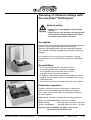
Installation
Location
• Locate the autocast universal® 230 in a clean dry room.
• Ensure that the room is sufficiently spacious
• Do not position the autocast universal® 230 close to ovens or
other heat generating devices
• The autocast universal® 230 is a bench unit.
Bench height, 85 – 90 cm /33 1 ⁄ 2 – 35 1 ⁄ 2 ”.
• Ensure that the bench is sufficiently stable and does not
wobble (minimum carrying capacity 100 kg/220 lbs.)
• The distance between the wall of the room and the back
panel of the machine should be approximately 20 cm/8”.
• Align the unit by using a spirit level and the adjustable legs.
• Ensure that the working area is well illuminated.
Electrical connection
The unit is connected to the power supply via a grounded
safety socket. Distance from unit is 1 metre.
Connected load:
Cable length:
Socket:
230 V, 3-phase, 50-60 Hz,
4,6 kVA
2m
protected by 1 x16 A slow acting
Neozed fuse
Argon supply
Use only argon of the following classification:
Argon 4.8 HR 99.998% to DIN 32526 or higher purity
Size of argon cylinder:
10 litres min.
• Secure the argon cylinder with a chain to prevent it from
falling over
• the argon cylinder at a maximum distance of 1 metre from
the machine
• Connect the pressure regulator to the argon cylinder using
an open ended wrench
Push the argon hose onto the coupling (argon) in the back
panel of the unit and connect the other end to the pressure
regulator using a hose clamp.
Always make sure that the valve at the gas bottle
is opened and that there is enough gas in the gas
container.
autocast universal® 230 Casting System
Installation
Stand 1. 9. 03
B 16
Instructions for the
autocast universal® 230
Casting Unit
Start-Up
• Open the argon cylinder and the cylinder pressure regulator
at the stop valve (K)
• Set the secondary argon pressure (I) to 5 bars at the cylinder
pressure control (J )
• Connect the unit to the power supply
• Turn the unit on at the main switch (D).
A signal will sound to let you know the unit is ready.
• Open the chamber door (C).
¡
The terms are explained on
page B34 and B35.
Positioning the crucible in the crucible
holder
Pure copper crucible
• Select the crucible for titanium (pure copper crucible) –
or for the selected alloy (combination crucible) support,
ceramic crucible and crucible electrode.
When casting with alloys, a ceramic crucible
(Order No. 090-161-00) is inserted into the copper crucible
support (Order No. 090-160-00).
A special crucible electrode (Order No. 090-162-00) is
attached to the crucible support with a wrench.
The rounded point should protrude slightly from the
ceramic pan.
¡
Attention:
Use one ceramic crucible and
one crucible electrode for each
separate alloy.
Do not immerse ceramic crucible
in cold water to cool off.
Crucible holder, ceramic crucible and crucible electrode
• Place the clean and dry crucible (F) with the sprue facing
forward, horizontally on the bars of the crucible holder.
• Push the crucible (F) to the back of the melting chamber until
its corner support fits into the grooves of the bars, and the
nose of the crucible clicks audibly into the crucible holder (G).
¡
autocast universal® 230 Casting System
For premature removal of
the crucible please push the
CAST button.
Operation of the autocast universal
Stand 21.7.04
B 17
Positioning the melting material (L)
a) Titanium
• Place the required titanium ingot (18 g, 22 g, 31 g, 36 g, 40 g)
on the crucible with the flat surface down (F)
• The positioning rings on the crucible determine the exact
position of the titanium casting metal on the crucible.
clearance
b) Alloys
• Filling the crucible with metal (alloys):
Take notice that there is contact between the metal and
crucible electrode, as well as the individual metal pieces.
Place the metal pieces in the center and make sure that
there is less metal behind the electrode. (During the melting
process the metal is not visible behind the light arc).
Setting the electrode clearance
a) Titanium
• The distance between the tip of the electrode and the
surface of the metal must be 5 mm.
• Open the electrode clamp (M) with a ring wrench (A/F 7 mm).
• Set the electrode clearance to 5 mm using the gauge
provided.
wrong
right
b) Alloys
• The distance of the electrode remains the same (when
compared to titanium casting).
• The distance between the crucible electrode and the upper
melting electrode is 15 mm.
¡
Important: The triangular tip
of the electrode (N) must always
have an angle of 50°.
50°
• The height of the electrode does not have to be changed
when casting titanium or alloys.
• To replace the electrode (N) see page B 30.
Location of the ring-support plate
• Switch on the main switch (D).
• An audible signal and the green light (mains power supply)
indicate that the unit is ready for operation.
• Open the cylinder pressure regulator to start the flow of
argon gas.
• Place the support disk (O) on the mandrel in the casting
chamber (B) with the knobs upwards.
• Place the ring-contact plate (P) on the support disk (O).
• The ring-contact plate (P) is moved up and down by the
rocker switch (Q).
• When the rocker switch is at the centre position “0” the
ring-contact plate remains stationary in its current position.
autocast universal® 230 Casting System
Operation of the autocast universal
Stand 1. 9. 03
B 18
¡
Important:
The ”0“ position is for
positioning the muffel
on the contact plate.
Always move the switch to
its upper position for melting
and casting.
Ceramic seal
The ceramic seal (R) serves to seal the ring (S) against the
melting chamber (A). It provides an effective seal between the
ring and the pouring funnel (T) during the entire melting and
casting process.
Seals that are dry or have not been damaged can be reused
up to 3 times. Ceramic seals are available for high temperature
casting (Order No. 090-012-60)
¡
Important!
Damaged or wet seals should
not be used as these will cause
casting failures.
Ceramic seal (R)
Positioning the muffel
• Remove the muffel from the heating oven.
• Align the seal (R) to the funnel (S).
• Place the casting ring into the casting chamber (B) with its
flat side towards the back panel.
• Place the muffel (S) on the centre of the muffel-contact
plate (P) so that the downsprue is exactly beneath the
pouring funnel (T).
• By switching the rocker switch (Q) upwards, press the
muffel against the pouring funnel (T).
Funnel (S) with ceramic seal (R)
autocast universal® 230 Casting System
Operation of the autocast universal
Stand 21.7.04
B 19
¡
autocast universal® 230 Casting System
Do not dislocate the seal when
inserting the muffel! Do not tilt
the muffel during insertion!
Leave the rocker switch in the
upper position.
Operation of the autocast universal
Stand 1. 9. 03
B 20
Initiation of the automatic melting and
casting process when using titanium
• Open the argon valve at the gauge connected to the bottle.
• Ajust the gas pressure at 5 bar.
• Close chamber door (C).
• Set the turnbutton at the selected titanium quantity.
• Press the start button.
• Melting and casting commences automatically.
• The yellow LED indicates the commencing of the process.
Blinking
= Evacuation of chambers
Illuminated
= Melting Casting
• While casting, pressure and vacuum values may be
observed at the pressure gauge on the machine:
Green needle = Vacuum in casting chamber = – 1 bar
Black needle
= pressure in melting chamber = 0,97 bar.
¡
autocast universal® 230 Casting System
When casting titanium the
inverter value is always 100%.
This value is not displayed and
cannot be altered.
Operation of the autocast universal
Stand 1. 9. 03
B 21
Sequence while casting titanium
1. The melting chamber in briefly flushed with argon.
2. Both chambers are evacuated.
3. The melting chamber is flooded with argon and the arc
ignites while the casting chamber is still being evacuated.
4. After a melting time of:
Ti 18 / 22 g
t s = 32 s
Ti 31 g
t s = 43 s
Ti 36 g
t s = 49 s
Ti 40 g
t s = 60 s
The crucible automatically tilts the melt into the casting
chamber.
5. The argon pressure in the melting chamber raises to
1,4 bar.
6. The delay time amounts to 40 seconds.
7. The pressures in casting and melting chamber are relieved.
8. The completion of the process is indicated by a beep.
Danger
autocast universal® 230 Casting System
Never open the chamber door
before completion of the whole
process.
Operation of the autocast universal
Stand 1. 9. 03
B 22
Manipulating of the process
1. Reduction of melting time:
Pressing the “CAST” button initiates premature tilt of
the melt.
2. Extension of melting time:
Pressing the “START” button at least 5 seconds before
elapse of melting time prolongs the melting process for up
to 65 seconds.
For reference: 5 seconds before elapse of melting time,
a beep indicates the completion of the process.
3. Abortion of process:
Melting and casting process may be aborted at any time
by pushing the STOP button. The crucible does not tilt.
All electric proceedings are interrupted and the chambers
are relieved.
After elapse of a safety period (40 s) the end of processes
is indicated by a beep.
Do not open chamber door
prematurely!
Danger
Prefixed parameters for titanium processing:
– Flushing
4s
– Evacuation
max. 15 s
– Flooding
60 s
End of process
• After opening the chamber door, the ring is removed by
flipping of the rocker switch to the bottom position.
• Remove ring and crucible and quench both in cold water.
Danger of burns!
Danger
• Remove titanium residues from crucible.
• Wipe dry the crucible.
autocast universal® 230 Casting System
Operation of the autocast universal
Stand 1. 9. 03
B 23
Casting of alloys:
Start of melt and casting process when
using alloys
Set the rotary switch to alloys.
The set power of the iverter appears on the LED display.
The setting for different alloys is done manually by rotating
the potentiometer marked “POWER” to the desired setting.
autocast universal® 230 Casting System
Operation of the autocast universal
Stand 1. 9. 03
B 24
¡
Non-precious alloys are generally
melted at 50% inverter power.
Small amounts can be melted from
30% on up, larger amounts with
a maximum of 65% inverter power
(vgl. 29 – 32).
¡
Precious metals are generally melted
with 15% inverter power.
Small amounts can be melted from
10% on up, larger amounts with a
maximum of 35% (see 29 – 32).
• Preset the inverter power with the rotary switch “POWER”.
• After stocking the machine with alloy and positioning of
the ring (see B17) press the “START”-button.
• ➯ The pressure-respectively time – controlled process
of melting begins. Pressure- and vacuum-values can be
observed during the whole process at the pressure
gauge (see B21).
• As soon as the arch ignites, the power can be readjusted at
any time by turning the rotary switch to higher or lower
settings.
• After all ingots have completely coalesced, press the
“CAST” button.
¡
After the electric arc has ignited, the
melting process can be monitored
through the darkened viewing
window. At low output settings, the
second darkened window can be
pushed aside, thereby allowing
better visual control of the melting
process.
In case of non ignition of the arch the
melting process may be interrupted
by pressing the “STOP”-button, or
by turning the main switch. Check
contact of the crucible electrode to
the alloy!
autocast universal® 230 Casting System
Operation of the autocast universal
Stand 1. 9. 03
B 25
At a power output higher than
50%, the second safety glass has
to stay, otherwise there is a chance
of eye damage due to the bright
stream of light.
¡
If after 90 seconds the CAST button
is not pressed, the crucible will tilt
automatically.
• The remaining sequence is the same as casting with
titanium (Page B 22).
Interruption of process:
The melting- and casting-process may be interrupted at any
time by pressing the “STOP”-button without tilting the
crucible.
All electrical proceedings are cut off and the chambers are
flooded with air.
After elapse of a safety block of 40 seconds an acustic signal
indicates the termination of the process.
Do not open the chamber door
before termination of the process!
Crucible holder with ceramic
crucible cannot be quenched in
water. The sudden cool down
could break the crucible.
Parameters for processing alloys:
– Flushing time
4s
– Vacuum time
max. 15 s
– Cooling time
10 s
Additional function Crucible control
The tilt function of the crucible may be even controlled with
open door of the casting chamber, by pressing the “CAST”
button. With this function, also a mislocated crucible may be
released and removed.
autocast universal® 230 Casting System
Operation of the autocast universal
Stand 1. 9. 03
B 26
Maintenance
and setting
Inspection before every casting process
• Check the funnel between the two chambers for casting
residues and clean if necessary.
• Check the tip of the electrode (N) and grind it to the correct
shape if necessary.
• Use only a dry clean crucible and dry clean ceramic seals.
• Sand-blast seriously oxidised crucibles and electrodes in the
sand blaster.
¡
Clean copper crucibles and electrodes thoroughly after sand blasting.
If work on electrical components
or conductors is required, always
seek the help of a second person
to operate the main switch if
necessary.
Replacing the electrode (N)
• Loosen the electrode clamp with a wrench (A/F 7 mm)
• Remove the electrode from the clamp.
• Grind the tip of the electrode to the correct shape
(see page B 18).
• Replace the electrode and tighten the electrode clamp (M).
Removing the funnel (T)
• Using the pin pliers, release the ring nut in ceiling of the
casting chamber
• Remove the funnel upwards
• When replacing the funnel, tighten the ring nut.
Observe the position of the ring nut. Do not forget the O
ring.
autocast universal® 230 Casting System
Maintenance and setting
Stand 1. 9. 03
B 27
Replacing the safety glass
The safety glass can be removed by pressing the tension
spring.
Care
• The autocast universal® 230 requires only a minimum
of care.
• Use a damp cloth to clean the surface.
Weekly maintenance
• Cleaning the sinter filter:
Remove radiator from the melting chamber.
Unscrew filter – if necessary with a fork spanner SW 17 mm
from the melting chamber.
Clean the filter in ultrasonic bath.
After drying reassemble the filter in the reverse sequence.
• Clean the reflector metal sheets in the casting chamber.
• Remove the safety glass on the inside of the door and
clean it if necessary using a paper towel soaked in solvent.
If the glass is damaged or soiled by splashes of metal,
replace it.
autocast universal® 230 Casting System
Maintenance and setting
Stand 1. 9. 03
B 28
Error signals –
causes and remedies
¡
If an error occurs during operation or during the
process, it is displayed on the touch panel and a buzzer
is heard at intervals of one sec. When the error has
been corrected, the signal must be acknowledged by
touching Quit.
The following problems may occur:
Signal
Check door / lift
Cause
Started with door open
Started with casting mould not
clamped (toggle switch not
up)
No quantity selected Started without selecting melt
quantity (fig. 2)
Effect
Remedy
Process start
prevented.
No value in
service mode
Flip toggle
switch to upper
position, close door
Process start
prevented.
No value in service
mode
Select melt quantity
No arc current
Plasma source does not generate Process aborted.
current despite inverter being
No value in service
switched on
mode
● No material in crucible
● Defective electrode
● Defective inverter
Chamber
temperature
Temperature in casting chamber No effect on current Switch unit off and
too high
process, new process allow to cool
start prevented
Ring defective,
STOP!
Pressure increase in casting .
Pressure monitoring Replace ring.
chamber during melting process system detects
Check seal.
due to defective ring
continuous excessive
pressure (min. 3 sec.)
in melting chamber.
Melting process
aborted. Cool off.
No tilting of crucible.
No value in service
mode.
autocast universal® 230 Casting System
Error signals – causes and remedies
Place material in
crucible
Check electrode
Inverter check
only by approved
electrician!
Stand 1. 9. 03
B 29
Technical service
Should any other defects or malfunctions occur,
please contact the
Dentaurum Customer Service Dept.
J. P. Winkelstroeter KG
Turnstraße 31 · 75228 Ispringen
Telephone + 49 72 31/ 80 34 22
Fax + 49 72 31/ 80 34 09
We recommend that you subscribe
a maintenance and service contract with us.
Please contact us for details.
autocast universal® 230 Casting System
Technical service
Stand 1. 9. 03
B 30
Accessories for
autocast universal® 230
Casting Unit
Included with basic unit:
Titanium casting metal (5 x 31 g)
1 melting crucibles
1 receptacle for crucible alloys
5 ceramic crucibles
5 ceramic crucibles (large)
1 package crucible electrodes
1 casting ring plate (907-271-00)
1 support disk
1 test mold
1 hose (2.5 meter in length)
1 cylinder pressure reducer
1 set electrodes (3 pieces) (40mm long)
1 set ceramic seals (100 pieces)
1 tool kit consisting of:
– 1 plate for crucible
– 1 pin-type face wrench
– 1 pair of crucible tongs
– 1 pair of tongs for removing crucible
– 1 ring wrench SW 7
Cleaning agents
for cleaning melting chamber:
Pump spray Lubrofilm
100 ml
autocast universal® 230 Casting System
Accessories
Ord.-No. 112-050-00
Stand 1. 9. 03
B 31
Spare parts list
No.
4b
9
8
Order No.
1
Crucible holder
907-001-02
2
Melting crucible
090-110-00
3
Electrode (3 piece)
907-001-03
4
Electrode clamp
907-617-10
4b
Spannhülse mit Spritzschutz
907-617-60
5
Copper funnel
907-571-10
6
Ceramic insulation
907-428-00
7
Ceramic seal
(high temperature resistant)
090-012-60
8
Sinter filter
908-324-00
9
Fixation of cast funnel
907-001-17
Vacuum pump
907-001-12
Fuse 2.5 A,t
908-802-00
Fuse 0.5 A,t
908-909-00
Pressure gauge
908-940-00
Claw wrench
907-001-14
Tongs
907-001-15
Receptacle for crucible alloys
090-160-00
Ceramic crucible (10 pieces)
090-161-00
Ceramic crucible – large (10 pieces)
090-161-50
Crucible electrode (5 pieces)
090-162-00
11
autocast universal® 230 Casting System
Replacement parts
Spare parts list
Stand 1. 9. 03
B 32
autocast universal® 230 Casting System
Machine diagrams
Stand 1. 9. 03
Power supply plug
Main switch
Component E
with SPS
Double
pressure
gauge
Operating
panel
Vacuum
pump
Gas-inlet valve 1
Lifting cylinder
Ventilator 1
Crucible tilting magnet
Relief valve
Pressure controller
Electric-arc power
supply with HF ignition
Ventilator 2
Argón
Pressure sensor,
casting chamber
Vacuum value
Gas-outlet valve
Gas-outlet choke
Machine diagrams
Gas-inlet valve 2
Cable channel
B 33
Individual elements of the
autocast universal® 230
E
G
A
B
C
D
E
G
Q
Melting chamber
Casting chamber
Chamber door
Main switch
Double pressure gauge
Touch panel
Rocker switch
D
A
Q
B
C
H
I
Pressure gauge
H
I
J
K
Primary pressure gauge
Secondary pressure gauge
Pressure controller
Stop valve
K
J
autocast universal® 230 Casting System
Individual elements
Stand 21.7.04
B 34
Melting and
casting chamber
A Melting chamber
B Casting chamber
C Chamber door
F Crucible
G Crucible holder
L Ingot
M Electrode clamp
N Electrode
O Support disk
P Ring contact plate
R Ceramic seal
S Ring
T Funnel
autocast universal® 230 Casting System
Melting and casting chamber
Stand 1. 9. 03
B 35
EEC-Declaration of Conformity
Dentaurum J. P. Winkelstroeter KG
Turnstraße 31
D-75228 Ispringen
hereby declares that the design and construction of the laboratory equipment described below,
including the version marketed by us, comply with the basic regulations governing safety and health
as stated in the EEC Guidelines. This declaration will become invalid if the laboratory equipment is
modified or altered in any way without our prior consent.
Description of the unit:
Autocast Universal 230 (090-155-00)
Type of Unit:
Order-No.:
Casting Unit
122-001
EEC Guidelines:
EEC Guideline for machine
modified guideline RL 98/79/EG
98/37/EG
Electical equipment used within certain
voltage limits
modified guideline RL 93/68/EWG
Electromagnetic compatibility
modified guideline RL 91/263/EWG
modified guideline RL 92/31/EWG
modified guideline RL 93/68/EWG
Applied unified standards:
EN 292; EN 55011; EN 60335-1
Applied national standards
and technical specifications:
DIN VDE 0100; DIN VDE 0110; DIN VDE 0544
DIN VDE 0700; DIN VDE 0721; DIN V 19250
Date and manufacturer signature: 09.06.04
Signatory:
autocast universal® 230 Casting System
73/23/EWG
89/336/EWG
..........................................................
–i.V.Dipl.Ing.(FH)K.Merkle–
Production Manager
Declaration of Conformity
Stand 9.6.04
B 36
Gießsystem
Operating Instructions
Accessories and
replacement parts
Index
C Accessories and spare parts
Materials for crowns and bridges made of titanium
Materials for titanium model casting
Contents of rematitan® finishing kit for titanium casting
System components
Guarantee
autocast universal® 230 Casting System
C
C
C
C
2
5-7
8-9
10 - 12
C 13
Index
Stand 1.9. 03
C 1
Materials for crowns and bridges of
Tritan titanium casting metal
0483
Tritan titanium casting metal, Ti
Weight
Ingot Height
approx. 18 g 21 mm 11.5 mm
approx. 22 g 21 mm 14.3 mm
approx. 31 g 25 mm 14.3 mm
approx. 36 g 27 mm 14.3 mm
approx. 40 g 27 mm 15.8 mm
1 (crowns/bridges)
250
500
500
500
500
g
g
g
g
g
Ord.-No.
Ord.-No.
Ord.-No.
Ord.-No.
Ord.-No.
100-100-50
100-101-50
100-102-50
100-103-50
100-105-50
rematitan® M – Ti4
approx. 31 g 25 mm 14.3 mm 1 kg
Ord.-No. 100-107-00
rematitan Plus investment
80 x 250 g
32 x 250 g
Ord.-No. 107-600-00
Ord.-No. 107-610-00
®
20 kg
8 kg
Special mixing liquid for crowns and bridges
Concentrate
1l
Ord.-No. 107-602-00
rematitan® Plus investment
Muffle base with sprue former:
Size 3
Ord.-No. 106-850-50
Size 6
Ord.-No. 106-851-00
Size 9
Ord.-No. 106-852-00
Muffle rings, elastic:
Size 3
Ord.-No. 106-840-00
Size 6
Ord.-No. 106-841-00
Size 9
Ord.-No. 106-842-00
Muffle rings to be used in accordance with the size of base.
autocast universal® 230 Casting System
Blue wax wire on rolls
2.5 mm 250 g
round
3.0 mm 250 g
round
3.5 mm 250 g
round
4.0 mm 250 g
round
5.0 mm 250 g
round
Ord.-No.
Ord.-No.
Ord.-No.
Ord.-No.
Ord.-No.
111-825-00
111-830-00
111-835-00
111-840-00
111-850-00
Hard wax wire on rolls
2.5 mm 250 g
round
3.0 mm 250 g
round
3.5 mm 250 g
round
4.0 mm 250 g
round
5.0 mm 250 g
round
Ord.-No.
Ord.-No.
Ord.-No.
Ord.-No.
Ord.-No.
111-425-00
111-430-00
111-435-00
111-440-00
111-450-00
Accessories and replacement parts
Stand 1.9. 03
C 2
Trinell investment:
Special Speed Liquid
Trinell Mixing Liquid
Trinell Powder
1000 ml
1000 ml
28 x 250 g
Ord.-No. 107-655-00
Ord.-No. 107-653-00
Ord.-No. 107-654-00
rematitan® Ultra investment:
7 kg Container
Mixing Liquid
1l
Ord.-No. 107-650-00
Ord.-No. 107-651-00
Investment system especially for Trinell and rematitan® Ultra
investment materials.
Application: crown and bridge
Ring size = 48 mm, Ring size = 65 mm,
Ring size = 88 mm
A
B
C
A Muffle rings, stainless steel, 2 sizes (, )
Ord.-No. 106-801-00
1 piece
Ord.-No. 106-802-00
1 piece
B Muffle base, with sprue former, 3 sizes (, , )
Ord.-No. 106-850-50
1 piece
Ord.-No. 106-851-00
1 piece
Ord.-No. 106-852-00
1 piece
C Fixing ring for connecting muffle ring and base,
3 sizes (, , )
Ord.-No. 106-845-00
1 piece
Ord.-No. 106-846-00
1 piece
Ord.-No. 106-847-00
1 piece
D Kera-Vlies. Asbestos free liner.
Size: 1.0 x 50 mm
25 m
Ord.-No. 127-250-00
D
autocast universal® 230 Casting System
Accessories and replacement parts
Stand 1.9. 03
C 3
Cervical wax:
StarWax C
50 g
Ord.-No. 120-212-00
Modelling waxes:
Star Wax CB green
50 g
Ord.-No. 120-201-00
Modelling waxes:
Star Wax CB beige (opaque)
50 g
Ord.-No. 120-202-00
Milling wax:
Star Wax M
50 g
Ord.-No. 120-211-00
Lubrofilm®
Degreases wax surfaces. Guarantees bubble-free flow of
investment.
Note! Also can be used as a silicone surface tensionreducing agent.
Pump spray
Refill bottle
100 ml
1000 ml
Ord.-No. 112-050-00
Ord.-No. 112-051-00
Folident Mini thermoforming unit
for plastic foils.
Set includes:
Moulding pot/foil holder
100 foils each of 0.6 and 0.1 mm
Ord.-No. 120-130-00
Replacement foils: 0.6 mm 100 pieces Ord.-No. 120-131-00
0.1 mm 200 pieces Ord.-No. 120-132-00
Ceramic seals C
100 pieces
autocast universal® 230 Casting System
Accessories and replacement parts
Ord.-No. 090-012-60
Stand 1.9. 03
C 4
Materials for titanium model casting
0483
Tritan titanium casting metal, Ti 1 (model casting)
Weight
Ingot Height
approx. 31 g 25 mm 14.3 mm 500 g Ord.-No. 100-102-50
approx. 36 g 27 mm 14.3 mm 500 g Ord.-No. 100-103-50
approx. 40 g 27 mm 15.8 mm 500 g Ord.-No. 100-105-50
The ingot dimensions are suitable for the rematitan®
titanium casting system.
Only ingots of 31 g or more are used for model casting.
Use 36 g ingots for more extensive constructions.
rematitan® M-Ti4
approx. 31 g 25 mm 14.3 mm 1 kg
Ord.-No. 100-107-00
rematitan® Plus Investment
80 x 250 g sachets
20 kg
Ord.-No. 107-600-00
32 x 250 g sachets
8 kg
Ord.-No. 107-610-00
rematitan® model casting mixing liquid
1l
Ord.-No. 107-601-00
Approx. 3.2 litres are needed for 20 kg.
Plastic muffle rings of Rema®-Form
80.5 mm Height 54,5 mm
red, 1 piece
Ord.-No. 127-307-00
71.0 mm Height 54,5 mm
green, 1 piece
Ord.-No. 127-306-00
78.0 mm Height 70,0 mm
blue, 1 piece
Ord.-No. 127-308-00
Base plate for waxing-up models
Rapid fixing of the rings.
Suitable for all rings.
1 piece
Ord.-No. 127-309-00
Plastic sprue formers
5 pieces
autocast universal® 230 Casting System
Accessories and replacement parts
Ord.-No. 090-027-00
Stand 1.9. 03
C 5
Wax wire for sprue channels
3.0
3.5
4.0
5.0
mm
mm
mm
mm
250
250
250
250
g
g
g
g
round
round
round
round
Ord.-No.
Ord.-No.
Ord.-No.
Ord.-No.
111-830-00
111-835-00
111-840-00
111-850-00
Ord.-No.
Ord.-No.
Ord.-No.
Ord.-No.
108-700-00
108-701-00
108-710-00
108-711-00
Material
autocast universal® 230 Casting System
Rema®-Sil
1
1
5
5
Gumex N
Undercut filler
650 g
Ord.-No. 168-015-50
rematitan®
Cold model hardener
Ord.-No. 167-305-00
Lubrofilm®
Surface tension-reducing agent for wax and
silicone
100 ml
Ord.-No. 112-050-00
1000 ml
Ord.-No. 112-051-00
Septisol
Gypsum-gypsum and gypsum-silicone release
agent
100 ml
Ord.-No. 108-720-00
1000 ml
Ord.-No. 108-721-00
kg
kg
kg
kg
component
component
component
component
A
B
A
B
Accessories and replacement parts
Stand 1.9. 03
C 6
attachments
0483
T-Attachment. Easy to activate or exchange. Comes in 90° or 36°.
Intracoronal retentive element which can be stress free welded
into the cavity of the crown by means of a laser. Both versions
also available as burnout plastic preformed females.
• Attachment made of pure titanium
• Prepared for laser welding
• With screw easy to activate
• Height reductable, approx. 40%
• Easy to place
• Low male boxing
• Replaceable male
• Castable preformed plastic female
• Male boxing can be glued into partial denture
• 2 Attachment shapes for upper and lower jaw
• No alteration of metal structure if laser welding is applied
B/D
C/A
Components A– N 1 piece each.
A 90° complete Ti Ti
B 36° complete Ti Ti
C 90° complete Ti-plastic-female part
D 36° complete Ti-plastic-female part
E plastic female
F titanium female
G male 90°
H male 36°
I male-part casing
J activating screw
K tapered nut
L parallel holder
M activating screwdriver
N tapered-nut key
Starter-Set
1 Pack
E/F
H
G
J
I
L
K
M
Availability: rematitan® attachment Starter Set.
Contents:
1 Parallel holder
1 Activation screwdriver
1 Conical nut key
Ord.-No.
Ord.-No.
Ord.-No.
Ord.-No.
Ord.-No.
Ord.-No.
Ord.-No.
Ord.-No.
Ord.-No.
Ord.-No.
Ord.-No.
Ord.-No.
Ord.-No.
Ord.-No.
Ord.-No.
240–010–00
240–020–00
240–012–00
240–022–00
240–030–00
240–031–00
240–015–00
240–025–00
240–035–00
240–036–00
240–037–00
240–040–00
240–041–00
240–042–00
240–001–00
rematitan® attachments: Instructions for use 1–6
N
autocast universal® 230 Casting System
1
2
3
4
5
6
Accessories and replacement parts
Stand 1.9. 03
C 7
Contents of Finishing Kit
11
1
12
13
2
14
3
5
6
Ord.-No. 135-500-00
(1)
ST cut-off disk, 40 mm
1
piece
(2)
STM cut-off disk, mini, 26 mm
2
pieces
(3)
TX cut-off disk, 22 mm
5
pieces
(4)
Ti tungsten carbide bur, mini
1
piece
(5)
Ti tungsten carbide bur, midi
1
piece
(6)
Ti tungsten carbide bur, maxi
1
piece
(7)
Ti tungsten carbide bur, maxi plus
1
piece
(8)
Aloxin stone, B, blue
1
piece
(9)
Aloxin stone, C, blue
1
piece
(10) Emery paper – 500 –
7
4
70
cm
(11) Rubber polisher, grey, disk
4
pieces
(12) Rubber polisher, red, disk
4
pieces
(13) Rubber polisher, red, rounded
4
pieces
(14) Rubber polisher, cylinder
4
pieces
(15) Polishing brushes, 20 mm, black
4
pieces
1
pieces
1
pieces
(16) Polishing brush, 60 mm,
Chungking bristles, double row
(17) Mini brush, black
(18) Tiger brilliant, polishing paste
10
60
g
(19) Mandrels for cylinders
1
piece
(20) Mandrels for disks / rounded polishers
6
pieces
(21) Mandrels for emery paper
1
piece
For information on ordering single set components,
refer to the list of “System Components” on page C 12.
19
20
21
16
15
17
autocast universal® 230 Casting System
Accessories and replacement parts
Stand 1.9. 03
C 8
X-Control
X-Ray unit for titanium castings. Easy to use with PolaroidInstant picture-system. A must for quality control.
Size: (W x H x D) 250 x 500 x 300 mm.
1 piece
Ord.-No. 090-140-00
Polaroid plain film for x-control
20 pieces
Technical data:
Electrical:
Connection:
Ord.-No. 090-142-00
220/240 V, 50/60 Hz
1.5 kVA
X-Ray stepped wedge
For adjustment of suitable exposure time.
1 piece
Ord.-No. 090-145-00
autocast universal® 230 Casting System
Accessories and replacement parts
Stand 1.9. 03
C 9
System components
Description
autocast universal® 230 casting unit
Melting crucible
Receptacle for crucible alloys
Ceramic seals
Crucible electrode
Ceramic seals C
Quantity
1 piece
1 piece
1 piece
10 pieces
5 pieces
100 pieces
Ord.-No.
090-155-00
090-110-00
090-160-00
090-161-60
090-162-00
090-012-60
0483
Tritan casting metal Ti 1
18 g, 21 mm, height 11.5 mm
250
22 g, 21 mm, height 14.3 mm
500
31 g, 25 mm, height 14.3 mm
500
36 g, 27 mm, height 14.3 mm
500
40 g, 27 mm, height 15.8 mm
500
rrematitan® M casting metal Ti4 31 g, 25 mm, height 14.3 mm 1
g
g
g
g
g
kg
100-100-50
100-101-50
100-102-50
100-103-50
100-105-50
107-107-00
rematitan® Investments
rematitan® Plus Plus Investment, 80 x 250 g
rematitan® Plus Investment, 32 x 250 g
rematitan® Plus mixing liquid
rematitan® Plus special mixing liquid
rematitan® Ultra investment material
rematitan® Ultra mixing liquid
Trinell Investment
Trinell Mixing Liquid
Trinell Speed Liquid
kg
kg
l
l
kg
l
g
ml
ml
107-600-00
107-610-00
107-601-00
107-602-00
107-650-00
107-651-00
107-654-00
107-659-00
107-655-00
Titanium
Titanium
Titanium
Titanium
Titanium
Titanium
Titanium
Titanium
20
8
1
1
7
1
28 x 250
1000
1000
wires
wire round, 0.4 mm, Länge 2 m
wire round, 0.7 mm, Länge 2 m
wire round, 1.0 mm, Länge 100 mm
wire round, 1.2 mm, Länge 100 mm
wire round, 1.5 mm, Länge 50 mm
wire rolled, height 0.5 mm, lenght 100 mm
wire rolled, height 0.25 mm, lenght 100 mm
1
1
10
10
1
10
10
roll
roll
pieces
pieces
piece
pieces
pieces
528-039-50
528-040-50
528-041-00
528-042-00
528-050-00
528-043-00
528-044-00
Muffle base with sprue former size 3
Muffle base with sprue former size 6
Muffle base with sprue former size 9
Muffle ring elastic size 3
Muffle ring elastic size 6
Muffle ring elastic size 9
Casting ring, stainless steel, size 3
Casting ring, stainless steel, size 6
Fixing ring, size 3
Fixing ring, size 6
Fixing ring, size 9
Muffle ring for model casting, 71 mm, green, height 54 mm
Muffle ring for model casting, 78 mm, blue, height 70 mm
Muffle ring for model casting, 80 mm, red, height 54 mm
Muffle base for muffle rings 127-306/-307/-308
1
1
1
1
1
1
1
1
1
1
1
1
1
1
1
piece
piece
piece
piece
piece
piece
piece
piece
piece
piece
piece
piece
piece
piece
piece
106-850-50
106-851-00
106-852-00
106-840-00
106-841-00
106-842-00
106-801-00
106-802-00
106-845-00
106-846-00
106-847-00
127-306-00
127-308-00
127-307-00
127-309-00
autocast universal® 230 Casting System
System components
Stand 1.9. 03
C 10
Description
Plastic sprue former
Muffle forceps
Kera-Vlies
Quantity
5 pieces
1 piece
25 m
rematitan® attachment
rematitan® attachment
rematitan® attachment
rematitan® attachment
Plastic female
Titanium female
Male 90°
Male 36°
Male-part casing
Activating screw
Fixing screw
Parallel support
Activating key
Key for fixing screw
90°
36°
90°
36°
complete
complete
complete
complete
Ti Ti
Ti Ti
Ti-plastic
Ti-plastic
rematitan® allergy platelets
Septisol gypsum-gypsum, gypsum-silicone release agent
Rema® Sil duplicating silicone
Component A
Component B
Component A
Component B
Gumex N undercut filler
rematitan® cold model hardener
round,
round,
round,
round,
round,
Wax
Wax
Wax
Wax
Wax
round,
round,
round,
round,
round,
hard,
hard,
hard,
hard,
hard,
wire,
wire,
wire,
wire,
wire,
2.5
3.0
3.5
4.0
5.0
mm,
mm,
mm,
mm,
mm,
piece
piece
piece
piece
piece
piece
piece
piece
piece
piece
piece
piece
piece
piece
3 pieces
Lubrofilm® surface tension-reducing agent for wax
and silicone
Wax wire
Wax wire,
Wax wire,
Wax wire,
Wax wire,
Wax wire,
1
1
1
1
1
1
1
1
1
1
1
1
1
1
roll
roll
roll
roll
roll
2.5
3.0
3.5
4.0
5.0
mm,
mm,
mm,
mm,
mm,
g
g
g
g
g
roll
roll
roll
roll
roll
Folident Mini thermoforming unit
Foils, 0.6 mm
Foils, 0.1 mm
autocast universal® 230 Casting System
250
250
250
250
250
g
g
g
g
g
240-010-00
240-020-00
240-012-00
240-022-00
240-030-00
240-031-00
240-015-00
240-025-00
240-035-00
240-036-00
240-037-00
240-040-00
240-041-00
240-042-00
100-110-00
100
1000
100
1000
ml
ml
ml
ml
112-050-00
112-051-00
108-720-00
108-721-00
1
1
5
5
kg
kg
kg
kg
108-700-00
108-701-00
108-710-00
108-711-00
1 piece
1000 ml
250
250
250
250
250
Ord.-No.
090-027-00
008-030-00
127-250-00
168-015-50
167-305-00
1
1
1
1
1
roll
roll
roll
roll
roll
111-825-00
111-830-00
111-835-00
111-840-00
111-850-00
1
1
1
1
1
roll
roll
roll
roll
roll
111-425-00
111-430-00
111-435-00
111-440-00
111-450-00
1 piece
100 pieces
200 pieces
System components
120-130-00
120-131-00
120-132-00
Stand 1.9. 03
C 11
Description
Modelling waxes StarWax CB green
Modelling waxes StarWax CB beige (opaque)
Milling wax StarWax M blue
Cervical wax Star Wax C red
Quantity
50 g
50 g
50 g
50 g
Ord.-No.
120-201-00
120-202-00
120-211-00
120-212-00
1 pieces
135-500-00
Separating discs:
ST separating discs, 40 mm
STM separating discs, 25 mm
TX separating discs, 22 mm
10 pieces
20 pieces
100 pieces
130-100-00
130-110-00
130-512-00
Ti-hard metal burs, mini
Ti-hard metal bur, midi
Ti-hard metal bur, maxi
Ti-hard metal bur, maxi plus
Aloxin points B, blue
Aloxin points C, blue
Emery cloth – 500 –
Rubber polisher grey, disk
Rubber polisher red, disk
Rubber polisher red, rounded
Rubber polisher clinders
5
1
1
1
12
12
25
100
100
100
100
pieces
piece
piece
piece
pieces
pieces
m
pieces
pieces
pieces
pieces
123-610-00
123-611-00
123-612-00
135-613-00
135-852-00
135-853-00
140-016-00
138-102-00
138-601-00
138-603-00
138-602-00
10 pieces
10 pieces
10 pieces
141-800-00
141-711-00
141-810-00
1 piece
1 piece
190-350-00
190-301-00
10 pieces
10 pieces
10 pieces
139-100-00
139-300-00
139-500-00
rematitan® finishing set
(for contents see page C 7)
Brushes for polishing, 20 mm, black
Brushes for polishing, 60 mm, 2 rows of bristles
Small brushes, black
Tiger, polishing paste, 400 g
Tiger Starshine Universal Finish, polishing paste, 50 ml
Mandrels for clinders
Mandrels for disk and lentil
Mandrels for emery cloth
autocast universal® 230 Casting System
System components
Stand 1.9. 03
C 12
All the use recommendations given in writing, verbally
or in instruction manuals result from our own experiences
and experiments.
They are not binding, including in respect of any protective
rights of third parties. The user himself remains responsible
for testing our products and recommandations. Any claims
for compensation which nevertheless occur and are based
on our use recommandations will always relate only to the
value of the goods delivered.
All recommendations for use given in writing, verbally or
in instruction manuals result from our own experiences and
experiments.
They are non commital including protective rights of third
parties. The user alone remains responsible for evaluating
our products and recommendations given.
Nevertheless, any claims resulting from recommendations
issued from our side will be only covered to the value of
goods delivered.
J.P. Winkelstroeter KG
Turnstraße 31 · 75228 Ispringen
Telephone +49 7231/80 34 22
Fax +49 7231/80 34 09
989-806-20 Printed by Dentaurum Germany
autocast universal® 230 Casting System
Guarantee
Stand 1.9. 03
C 13