1
Installation and maintenance instructions
For the competent person
Installation and maintenance instructions
ecoTEC plus
VU 80, 100, 120 kW
GB, IE
Table of contents
Table of contents
1
1.1
1.2
1.3
1.4
1.5
Notes on the documentation ..................................... 3
Storing documents .......................................................... 3
Applicability of the instructions ................................... 3
Identification plate........................................................... 3
CE label............................................................................... 3
Type overview ...................................................................4
2
2.1
2.2
2.3
2.4
Safety .................................................................................5
Safety and warning information ..................................5
Intended use......................................................................5
Basic safety information ................................................6
General requirements ..................................................... 7
3
Unit and functional description ................................11
4
4.1
4.2
4.3
4.4
4.5
4.6
Installation ......................................................................12
Scope of delivery ............................................................12
Transporting the unit .....................................................12
Dimension drawing and connection dimensions .....15
Requirements for the installation site .......................15
Wall-mounting the boiler...............................................16
Removing/fitting the front casing ..............................16
5
5.1
5.2
Gas installation ..............................................................17
Preparing for installation ..............................................17
Connecting the gas line.................................................17
6
6.1
6.2
6.3
6.4
Hydraulic installation ................................................. 18
Preparing for installation ............................................. 18
Connecting the heating flow and heating return....19
Connecting the condensate drain pipework........... 20
Connecting the discharge pipe to the expansion
relief valve on the heating installation ......................21
7
7.1
7.2
7.3
Flue gas installation ...................................................22
Preparing for installation .............................................22
Installing the flue pipe ..................................................22
Flue gas guiding opening .............................................22
8
8.1
8.2
8.3
8.4
8.5
8.6
Electrical installation .................................................24
Preparing for installation .............................................24
Opening/closing the electronics box .........................24
Establishing the mains connection and
connecting the pump group ........................................24
Connecting the controller ............................................26
Connecting additional units ........................................27
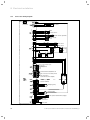
Connection wiring diagram .........................................28
9
9.1
9.2
9.3
9.4
9.5
9.6
Establishing operational readiness ........................29
Reading the temperature or pressure display ........29
Preparing the heating water .......................................29
Filling and purging the heating installation ............29
Preventing low water pressure .................................. 30
Filling the condensate siphon ......................................31
Checking the gas ratio setting.....................................31
2
10
10.1
10.2
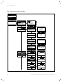
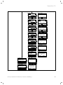
Operation ........................................................................33
Calling up the installer level ........................................33
Overview of the menu structure ............................... 34
11
11.1
11.2
11.3
11.4
11.5
Start-up ...........................................................................36
Switching on the boiler.................................................36
Installation assistant .....................................................36
Appliance configuration and diagnostics menu .....37
Using test programmes ................................................37
Checking the function of the boiler ......................... 38
12
12.1
12.2
Adapting the unit to the heating installation ....39
Overview of the parameters in the diagnostics
menu .................................................................................39
Handing the boiler over to the operator................. 43
13
13.1
13.2
13.3
13.4
13.5
Inspection and maintenance ................................... 44
Inspection and maintenance intervals ..................... 44
Inspection and maintenance work............................ 48
Using the function menu ............................................ 49
Removing/fitting the upper casing........................... 50
Carrying out maintenance work................................ 50
14
14.1
14.2
14.3
14.4
14.5
Troubleshooting ........................................................... 55
Contacting Vaillant customer service ...................... 55
Performing diagnostics ............................................... 55
Using the function menu ..............................................61
Running check programmes ........................................61
Resetting parameters to factory settings .................61
15
15.1
15.2
15.3
15.4
15.5
15.6
15.7
15.8
15.9
Replacing components ...............................................62
Preparing for and completing replacement work ..62
Removing/fitting the side section (if required) .....62
Replacing the gas valve................................................63
Replacing the burner ....................................................63
Replacing insulating mats........................................... 64
Replacing the fan .......................................................... 64
Replacing the heat exchanger ................................... 64
Replacing the PCB and/or the display ..................... 65
Ending repairs ................................................................ 65
16
16.1
16.2
16.3
Decommissioning ........................................................ 66
Temporarily shutting down the boiler ..................... 66
Permanently decommissioning the boiler .............. 66
Disposing of the boiler ................................................ 66
17
Vaillant Commercial Service ................................... 66
18
Technical data ...............................................................67
19
Glossary ......................................................................... 68
20
Appendix ........................................................................ 69
Index
...........................................................................................72
ecoTEC plus installation and maintenance instructions 0020134823_01
Notes on the documentation
1
Notes on the documentation
1.4
The following information is intended to help you throughout the entire documentation. Other documents apply in
addition to these Installation instructions. We accept no liability for any damage caused by failure to observe these
instructions.
Other applicable documents
> During installation, you must observe all the installation
instructions for the assemblies and components of the
system.
These installation instructions are enclosed with the various
system parts and supplementary components.
> Furthermore, observe all operating instructions enclosed
with components of the system.
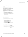
1.1
Storing documents
> Pass these installation instructions and all other applicable documents and, if necessary, any required tools to
the system operator.
The system operator should retain these instructions and
tools so that they are available when required.
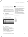
1.2
Applicability of the instructions
These instructions apply for the following products only:
Unit
Type designation
Article
number
Gas
Council
Number
ecoTEC plus
806 (VU GB 806/5-5)
0010010767
41-044-68
ecoTEC plus
1006 (VU GB 1006/5-5)
0010010780
41-044-69
ecoTEC plus
1206 (VU GB 1206/5-5)
0010010791
41-044-70
1
CE label
CE labelling shows that, based on the type
overview, the units comply with the basic
requirements of the following directives:
– Directive 2009/142/EC of the Council with amendments
"Directive for Harmonisation of Legal Regulations of the
Member States for Gas Consumption Appliances"
(Gas Appliances Directive)
– Directive 92/42/EC of the Council with amendments
"Directive Concerning the Efficiency of New Hot Water
Heating Boilers Fired by Liquid or Gaseous Fuels"
(Efficiency directive)
– Directive 2006/95/EC of the Council with amendments
"Directive Concerning Electrical Equipment for Use
Within Specific Voltage Limits" (Low voltage directive)
– Directive 2004/108/EC of the Council with amendments
"Directive Concerning Electromagnetic Compatibility"
The boilers comply with the type sample described in the
EC Type testing certificate
PIN no. CE-0085CM0415
The units comply with the following standards:
– EN 12828
– EN 15417
– EN 15420
– EN 50165
– EN 55014
– EN 60335-1
– EN 6100-3-2
– EN 6100-3-3
– prEN 15502-1
– prEN 15502-2
1.1 Type overview
> The article number of the unit can be found on the identification plate.
1.3
Identification plate
The identification plate of the Vaillant ecoTEC plus is
attached to the bottom of the boiler at the factory.
The article number of the gas-fired wall-hung boiler can be
found in the serial number. The seventh to sixteenth numbers constitute the article number.
The serial number is also located on a plate, which is placed
in a plastic fish plate behind the front flap on the underside
of the boiler. The serial number can also be shown in the
display of the boiler (¬ Operating instructions).
ecoTEC plus installation and maintenance instructions 0020134823_01
3
1
1.5
Notes on the documentation
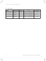
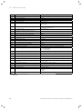
Type overview
Unit type
ecoTEC plus
Designated country
(designation in accordance with ISO 3166)
806 (VU GB 806/5-5)
Approval
category
Gas group
Nominal heat output
range [kW]
GB (Great Britain)
IE (Ireland)
II2H3P
Natural gas H - G20 - 2 kPa (20 mbar)
Propane - G31 - 3.7 kPa (37 mbar)
Propane - G31 - 5 kPa (50 mbar)
16 - 80
1006 (VU GB 1006/5-5)
GB (Great Britain)
IE (Ireland)
II2H3P
Natural gas H - G20 - 2 kPa (20 mbar)
Propane - G31 - 3.7 kPa (37 mbar)
Propane - G31 - 5 kPa (50 mbar)
20 - 100
1206 (VU GB 1206/5-5)
GB (Great Britain)
IE (Ireland)
II2H3P
Natural gas H - G20 - 2 kPa (20 mbar)
Propane - G31 - 3.7 kPa (37 mbar)
Propane - G31 - 5 kPa (50 mbar)
24 - 120
1.2 Type overview
4
ecoTEC plus installation and maintenance instructions 0020134823_01
a
Safety 2
2
Safety
2.1
2.2
Safety and warning information
> When installing the ecoTEC plus, you must observe all
the general safety information and the warning notes
that appear before all of the actions.
2.1.1
Classification of warnings
The warnings are classified in accordance with the severity
of the possible danger using the following warning signs
and signal words:
Warning
symbol
Signal
word
a
e
a
b
Danger!
Explanation
Imminent danger to life or
risk of severe personal
injury
Danger!
Risk of death from electric
shock
Warning.
Risk of minor personal injury
Caution.
Risk of material or environmental damage
Intended use
There is a risk of injury or death to the user or others, or of
damage to the product and other property, in the event of
improper use or use for which it is not intended.
The product is intended as a heat generator for closed hot
water/central heating installations and for hot water generation. The products referred to in this manual must only be
installed and operated in conjunction with the accessories
listed in the associated flue pipe installation manual.
Intended use includes the following:
– observance of accompanying operating, installation and
servicing instructions for the Vaillant product, as well as
all other components of the system
– installing and fitting the product in accordance with the
product and system approval
– compliance with all inspection and maintenance conditions listed in the instructions.
The use of the product in vehicles, such as mobile homes
and caravans, is not classed as intended use. Units that are
not classed as vehicles are those that are installed in a
fixed and permanent location (known as "fixed installation").
Installing and using the product in locations where it will be
subject to possible moisture or spray water is considered to
be improper use.
Any other use that is not specified in these instructions, or
use beyond that specified in this document, shall be considered improper use. Any direct commercial or industrial use
is also deemed to be improper.
The manufacturer/supplier is not liable for any claims or
damage resulting from improper use. The user alone bears
the risk.
Caution.
Improper use of any kind is prohibited.
2.1 Classification of warnings
2.1.2
Structure of warnings
Warning signs are identified by an upper and lower separating line. and are laid out according to the following basic
principle:
a
Signal word!
Type and source of danger!
Explanation of the type and source of
danger
> Measures for averting the danger
ecoTEC plus installation and maintenance instructions 0020134823_01
5
a
a
a
2 Safety
2.3
Basic safety information
> Notify the gas supply company or National Grid Transco
0800 111999 by telephone from outside the building!
> Observe the following safety information at all times.
What to do if you smell flue gas
European installation directive
Installation and maintenance of the boiler must only be performed by a competent person with valid accreditation from
the Health and Safety Executive in accordance with the
"Gas Safety (Installation and Use) Regulations 1998" (hereinafter abbreviated to "competent person" or "heating specialist company"). The existing regulations, rules and guidelines must be observed when doing so. The competent person is also responsible for inspection, maintenance and
repairs to the boiler, and alterations to the gas volume setting.
IE only: The installation must comply with the current Version of I.S.813 ‘Domestic Gas Installations’ and current
Building Regulations.
The current ETCI Regulations for installing electrical systems must also be observed.
Risk of poisoning and burns caused by escaping
hot flue gases!
Hot flue gas can escape and cause poisoning and burns if
the boiler is operated with an incompletely installed or flue
pipe or if the boiler is operated with internal leaks with the
front casing open.
> Operate the boiler for start-up and in continuous mode
only when the front casing is fitted and closed and the
flue pipe is completely fitted.
> For test purposes only (such as gas flow pressure testing), the boiler may be operated with the front casing
removed for short durations ONLY but must have a completely installed flue pipe.
What to do in an emergency if you smell gas
Installation errors, damage, tampering, unauthorised installation sites or similar can cause gas to escape and result in
a risk of poisoning and explosion. If there is a smell of gas
in the building, proceed as follows:
> Avoid rooms that smell of gas.
> If possible, open doors and windows fully and ensure
adequate ventilation.
> Do not use naked flames (e.g. lighters, matches).
> Do not smoke.
> Do not use any electrical switches, mains plugs, doorbells, telephones or other communication systems in the
building.
> Close the gas meter isolator device or the main isolator.
> If possible, close the gas isolator cock in the gas supply.
> Warn other occupants in the building by yelling or banging on doors or walls.
> Leave the building.
> If you can actually hear gas leaking, leave the building
immediately and ensure that others do not enter the
building.
> Alert the fire brigade and police when you are outside
the building.
6
Installation errors, damage, tampering with the unit, unauthorised installation sites or similar can cause flue gas to
escape and result in a risk of poisoning. If there is a smell of
flue gas in the building, proceed as follows:
> If possible, open doors and windows fully and ensure
adequate ventilation.
> Switch the boiler off.
> Check the flue gas routes in the boiler and the flue gas
pipes.
> In particular, check that the flue gas opening is not
blocked. If required, seek expert assistance for this.
Installation in rooms with ventilation
For open-flued operation, the unit must not be placed in
rooms from which the air is extracted using fans (for example, ventilation systems, extractor hoods, tumble dryer ventilation). These systems create negative pressure in the
room. As a result of the negative pressure, flue gas from
the opening is drawn through the annular gap between the
flue gas pipe and the shaft into the installation room.
The unit may only be operated dependent on the room air,
if simultaneous operation of the unit and fan is not possible.
> To interlock the fan and unit, install the Vaillant accessory multi-functional module 2 from 7.
> Please inform the system operator of the possible risk
from running exhaust fans.
Material damage caused by corrosion
To prevent corrosion on the boiler and also in the flue pipe,
note the following:
> Do not use sprays, solvents, chlorinated cleaning agents,
paint, adhesives or similar substances in the vicinity of
the boiler.
Under unfavourable circumstances, these substances may
cause corrosion.
Material damage due to improper use and/or
unsuitable tools
The use of unsuitable tools or improper use thereof may
cause damage, such as gas or water leaks.
> To tighten or loosen threaded connections, only use a
suitable open-ended spanner (combination wrench) – do
not use pipe wrenches, extensions, etc.
Changes to the surroundings of the boiler
Changes may not be made to the following equipment:
– the boiler
– the gas, air and water pipes and power lines
– the flue pipe
– the drain line and expansion relief valve for the heating
water
– constructional conditions that could affect the operational safety of the boiler
ecoTEC plus installation and maintenance instructions 0020134823_01
a
Safety 2
Using the correct gas type
Using the wrong gas type may cause a fault shutdown on
the boiler. Furthermore, ignition and combustion noise may
occur in the boiler.
> Observe the gas setting values in accordance with
¬ section 1.5.
Risk of death due to lack of safety devices
A lack of safety devices (e.g. expansion relief valve, expansion vessel) can lead to potentially fatal scalding and other
injuries, e.g. due to explosions.
The schematic drawings included in this document do not
show all safety devices required for correct installation.
> Install the necessary safety devices in the system.
> Inform the operator about the function and position of
the safety devices.
> Observe the applicable national and international laws,
standards and guidelines.
2.4
General requirements
2.4.1
Related documents
To ensure the safe installation and continued satisfactory
operation of your appliance, all works shall be carried out
by a competent installer fully conversant with the equired
current and up to date, acts standards, laws and regulations
relevant for this range of equipment at the time of installation. In addition any special requirements of Local Authorities, gas undertakings or insurers must be complied with.
Installers shall carryout a full site risk assessment and put
into place all necessary steps and procedures to comply
with Health and Safety at Work Act and ensure safety of
themselves and others with regard to manual handling and
working at height requirements.
Attention shall be paid to (but not restricted to) the following:
– Gas Safety (Installation and Use) regulations.
– Non Domestic Heating, Cooling and Ventilation Compliance Guide.
– All Building Regulations 2000 for England and Wales,(as
amended).
– (Includes Approved Codes of Practice and Approved Documents for building regulations e.g. L1, L2A, L2B, L8.)
– The Building Standards, Scotland, and any requirements
determined by the local authorities within.
– BS 7671 Requirements for electrical installations. IEE Wiring Regulations
– The Electricity at Work Regulations.
– The Clean Air Act 1993, 1968 and the 3rd Edition of the
1956 Clean Air Act. (installations exceeding 150kW)
– The Water supply (water fittings) regulations 1999.
– BS 5854 Code of practice for flues and flue structures in
buildings.
– BS EN 12828 Design of water-based heating systems.
ecoTEC plus installation and maintenance instructions 0020134823_01
– BS 6644 Specification for the installation of gas fired
hot water boilers with rated inputs between 70 kW (net)
and 1.8 MW (net) (2nd and 3rd family gases).
– I.S. 820 Non Domestic gas Installations (Ireland)
– BS 6700 Specification for the design, installation, testing
and maintenance of services supplying water for domestic use within buildings and their curtilages.
– BS 6880 Code of practice for low temperature heating
systems with outputs greater than 45 kW.
Part 1 Fundamental and design considerations.
Part 2 Selection of equipment.
Part 3 Installation, commissioning and maintenance.
– BS 6981 Installation of low pressure gas pipework of up
to 35mm in domestic premises.
– BS 4814 Specification for: Expansion vessels using an
internal diaphragm, for sealed hot water and heating systems.
– BS 7074 Application, selection and installation of expansion vessels and ancillary equipment for sealed water
systems.
Part 1 Code of practice for domestic heating and hot water.
Part 2 Code of practice for low and medium temperature
hot water systems.
– BS 7593 Code of practice for treatment of water in
domestic hot water central heating systems
– BS EN 13831 Closed expansion vessels with built in diaphragm
– BS EN 14336 Heating systems in buildings. Installation
and commissioning of water based heating systems.
Institute of Gas Engineers Publications:
– IGE/UP/1 (Edition 2) Strength testing, tightness testing
and direct purging of industrial and commercial gas
installations.
– IGE/UP/1A (Edition 2) Strength testing, tightness testing
and direct purging of small, low pressure industrial and
commercial natural gas installations.
– IGE/UP/1B (Edition 2) Tightness testing and direct purging of small natural gas installations.
– IGE/UP/ 7 (Edition 2) Gas in timber and light steel
framed buildings.
– IGE/UP/10 Installation of gas appliances in industrial and
commercial premises.
Part 1 Flued appliances.
7
a
a
a
2 Safety
2.4.2 Installation site
2.4.3 Gas supply
The installation site of the boiler should allow proper connection of the flue pipe to the boiler. In addition, there
should be adequate room for maintenance work and air circulation around the boiler.
The boiler must be set up in a separate installation room.
In case of installation of the boiler in an unusual location,
special procedures may be necessary and BS 5546 and
BS 6798 give detailed instructions on this aspect. The boiler
must be installed on a flat, vertical wall, which must be sufficiently robust to take the weight of the boiler. The boiler
may be installed on a combustible wall, subject to the
requirements of the Local Authorities and Building Regulations.
An existing gas meter should be checked to ensure that it is
capable of passing the rate of gas supply required.
The lines must be fitted in accordance with BS 6891. In IE in
accordance with the current issue of IS 813. The lines
between the gas meter and boiler must be of an appropriate size.
Do not use any lines that are smaller than the connection
to the boiler (25 mm). The complete system must be tested
for leaks and purged as described in BS 6891.
i
If the boiler is to be installed in a timber frame
house, the installation must be performed in
accordance with the Institute of Gas Engineers
Publication IG/UP/7 edition 2 "Guideline for gas
installations in wooden and light metal-clad residences".
b
Caution.
Risk of damage caused by aggressive
vapours and dust.
Aggressive vapours and dust in the installation room may cause corrosion damage to
the boiler and to the flue gas installation.
> Ensure that the boiler is room-sealed if
the air in the installation room contains
aggressive vapours or dust.
> Observe the following when choosing the installation site
and operating the boiler:
– Do not install the boiler in rooms prone to frost.
– Do not install the boiler in rooms in which the combustion air contains chemical substances, e.g. fluoride,
chlorine, sulphur, dust, etc. (e.g. sprays, solvents,
cleaning agents, paint, adhesives).
> Operate the boiler independently of room air or in a separate installation room, otherwise this may cause corrosion in the boiler and in the flue gas installation, if
– the combustion air supply contains the aforementioned substances,
– you install the boiler in hairdresser salons, painter's or
joiner's workshops, cleaning businesses or similar.
> Do not route the combustion air through an old oil furnace hearth, as this can also cause corrosion.
> When installing the unit, please observe the local condensate regulations,
– avoid horizontal sections in the condensate and flue
gas route.
The condensate connection must not be modified or
blocked.
8
2.4.4 Electrical connection
e
Danger!
Risk of death from electric shock!
If the boiler is not earthed, it may be electrically live if a defect occurs.
> Earth the boiler and the metal pipes that
are connected to the boiler.
A common, single-phase 230 V-, ~ 50 Hz electricity supply
fused to a max. 3 A must be provided for the boiler and its
additional controllers in accordance with the latest edition
of the directive BS7671 (IEE Wiring Regulations) and any
other local regulations that may apply. In IE reference
should be made to the current edition of the ETCI rules. The
method of connection to the power mains must provide a
means of completely isolating the boiler and its ancillary
controllers from the power mains. It is preferable to isolate
the boiler using a two-pin switch with a 3-mm contact opening on both pins. The isolator should be attached and
marked accordingly so that it is easily accessible and adjacent to the boiler.
2.4.5 System of parts through which water flows
Lines which do not form part of the usable heating surface
should be insulated to prevent heat losses and possible
freezing up, especially where the lines run under roofs and
ventilated cellar spaces. The drain connections must be easily accessible, so that the entire system including the boiler
and hot water system can be drained. The drain connections should be at least 1/2" (BSP nominal size) and must be
in accordance with BS 2879.
The water pipes must be thoroughly cleaned, especially
when connecting a new boiler to an existing system.
ecoTEC plus installation and maintenance instructions 0020134823_01
a
Safety 2
b
Caution.
Risk of material damage if the heating
water is treated with unsuitable frost or
corrosion protection agents!
Frost and corrosion protection agents may
cause changes in the seals, noises during
heating and may lead to further damage.
> Do not use any unsuitable frost or corrosion protection agents.
Permissible salt content
Heating water
characteristics
Unit
Low-salt
Saline
Electrical conductivity at
25 °C
mS/cm
< 100
100 - 1500
Appearance
Free of sedimentary
materials
pH value at 25 °C
8.2 - 10.01)
8.2 - 10.01)
< 0.1
< 0.02
Oxygen
Mixing additives with the heating water may result in material damage. However, no incompatibility with Vaillant boilers has been detected with proper use of the following
products over a long period.
> When using additives, follow the manufacturer's instructions without exception.
Vaillant accepts no liability for the compatibility of any additive or its effectiveness in the rest of the heating installation.
Additives for cleaning measures (subsequent
flushing required)
– Fernox F3
– Sentinel X 300
– Sentinel X 400
Additives intended to remain permanently in the
system
–
–
–
–
Fernox F1
Fernox F2
Sentinel X 100
Sentinel X 200
Additives for frost protection intended to remain
permanently in the system
– Fernox Antifreeze Alphi 11
– Sentinel X 500
> Inform the operator about the measures required if you
have used these additives.
> Inform the operator about the measures required for
frost protection.
ecoTEC plus installation and maintenance instructions 0020134823_01
mg/l
1) For aluminium and aluminium alloys, the pH value range is
restricted from 6.5 to 8.5.
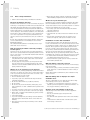
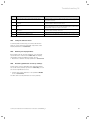
2.2 Guideline values for heating water: Salt content
Permissible water hardness
b
Caution.
Heating water that is extremely calciferous or corrosive or contaminated by
chemicals may cause damage to the
boiler.
Unsuitable heating water damages the
seals and diaphragms, blocks components
in the boiler and heating installation
through which the water flows, and causes
noise.
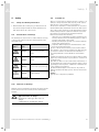
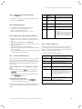
The heating water must fulfil the limit values based on the system volume in accordance with fig. 2.1 and, if required, must be
treated.
In addition, the national regulations with
regard to water treatment shall apply.
To treat the water, we recommend treatment plants that work according to the
reverse osmosis process.
> Condition the water for the initial filling
as well as the water for any subsequent
fillings.
9
a
a
2 Safety
3,6
3,3
3
80 kW
2,7
100/120 kW
2,4
y [mol/m3]
a
2,1
A
1,8
1,5
80 kW: A
1,2
0,9
100/120 kW: B
B
0,6
0,3
0,0
0
500
1000
1500
2000 2500 3000 3500 4000 4500 5000 5500 6000
x [l]
2.1 Water preparation depending on water hardness and system
volume
Key:
x System volume [l]
y Water hardness [mol/m3]
(1 mol/m3 corresponds to 100 mg/l CaCO3)
A Water treatment required
B Water treatment not required
2.4.6 Expansion relief valve
The boiler is supplied with a 6 bar presure relief valve,
which must be fitted to the boiler and drained to a safe but
visible location. The safety discharge pipe must be a minimum of 18 mm diameter and must be solely used for this
purpose.
Ensure that all components that are fitted in the heating
installation are suitable for a max. operating pressure of
6 bar.
2.4.7 Purging
The boiler is equipped with an automatic air vent. Other
measures need to be taken to allow the heating system to
be purged during filling and during commissioning either
manually or using an automatic air vent.
Risk of damage due to frost
Insufficient frost protection measures may cause frost damage to the heating installation
> Explain to the operator how to protect the heating installation against frost.
10
ecoTEC plus installation and maintenance instructions 0020134823_01
Unit and functional description 3
3
Unit and functional description
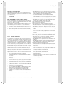
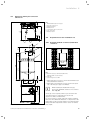
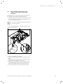
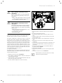
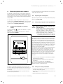
1
Construction and function
15
14
2
13
3
1
15
14
2
12
4
5
11
13
3
12
4
5
10
11
6
7
9
6
10
7
8
9
8
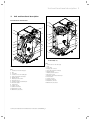
3.1 Functional elements (VU GB 806/5 - 5)
Key
1 Connection for the flue pipe
2 Fan
3 Gas valve
4 Connection for air intake pipe
5 Flue gas pressure cartridge
6 Return sensor
7 Water pressure sensor
8 Electronics box
9 Stainless steel heat exchanger
10 Pressure gauge
11 Flow sensor
12 Safety cut-out
13 Ignition electrode
14 Automatic air vent
15 Monitoring electrode
ecoTEC plus installation and maintenance instructions 0020134823_01
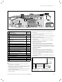
3.2 Functional elements (VU GB 1006/5 - 5 and
VU GB 1206/5 - 5)
Key
1 Connection for the flue pipe
2 Fan
3 Gas valve
4 Supply air collector
5 Flue gas pressure cartridge
6 Return sensor
7 Water pressure sensor
8 Electronics box
9 Stainless steel heat exchanger
10 Feed sensor
11 Safety cut-out
12 Ignition electrode
13 Automatic air vent
14 Monitoring electrode
11
4 Installation
4
Installation
4.1
Scope of delivery
The Vaillant ecoTEC plus is delivered pre-assembled in a
packaging unit.
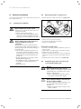
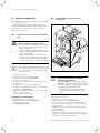
4.2
Transporting the unit
Important:
In regard to the regulations of 1992 concerning the manual
handling of loads, the unit exceeds the weight which can be
lifted by a single person.
General handling recommendations
4.1.1
>
>
>
>
Unpacking the boiler
Open the box by pulling on the tear-off strings.
Remove the boiler from its box.
Remove the protective film from all parts of the boiler.
Place the boiler so that it is vertical on the foot pad.
4.1.2
Checking the scope of delivery
> Check that the scope of delivery is complete and intact
(¬ table 4.1).
> Clear your path before lifting the unit.
> Use safe lifting techniques – keep your back straight –
and bend your legs at the knee.
> Hold the load as close as possible to your body. Do not
twist your body – instead, reposition your feet.
> If the unit is being lifted by 2 persons, ensure your movements are coordinated during lifting.
> Avoid bending your upper body - do not lean forwards or
to the side.
> Wear appropriate cut resistant and non-slip gloves to
protect yourself against sharp edges and maintain a safe
and secure grip.
> If required, get somebody to assist you in this.
Number Description
1
Hanging bracket
1
Unit
1
Enclosed documentation
- Installation and maintenance instructions
- Operating instructions
- Flue pipe installation manual
- Installation template
- Guarantee card
- Various stickers
1
Condensate siphon
1
Bag containing small parts (assembly kit)
- 1 x expansion relief valve, 6 bar
- 2 x service valves
- 6 x wood screws
- 6 x rawl plug, 10 x 60 mm
- 6 x washers
4.1 Scope of delivery
4.1.3
Disposing of the packaging
> Dispose of the cardboard packaging used on the ecoTEC
plus at a recovered paper collection point.
> Dispose of the plastic film and plastic filling at an appropriate plastic recycling site.
> Observe valid national regulations.
12
Unloading the box from the delivery van
It is recommended that two people lift the unit together.
> Lift the box using the straps provided.
> Use safe lifting techniques – keep your back straight –
and bend your legs at the knee.
> Hold the load as close as possible to your body.
> If the unit is being lifted by 2 persons, ensure your movements are coordinated during lifting.
> If required, get somebody to assist you in this.
Transporting the box from the delivery point to the
installation site – ground floor
It is recommended that two people lift the unit together.
> Use safe lifting techniques – keep your back straight –
and bend your legs at the knee.
> Hold the load as close as possible to your body.
> If the unit is being lifted by 2 persons, ensure your movements are coordinated during lifting.
> Clear your path before lifting the unit.
> Use safe lifting techniques – keep your back straight –
and bend your legs at the knee.
> Do not twist your body – instead, reposition your feet.
> Avoid tripping hazards, slippery or wet surfaces as well
as steps and stairs.
> If required, get somebody to assist you in this.
ecoTEC plus installation and maintenance instructions 0020134823_01
Installation 4
Transporting the box from the delivery point to the
installation site – first or higher floor, cellar
It is recommended that two people lift the unit together.
> Use safe lifting techniques – keep your back straight –
and bend your legs at the knee.
> Hold the load as close as possible to your body.
> If the unit is being lifted by 2 persons, ensure your movements are coordinated during lifting.
> Avoid bending your upper body - do not lean forwards or
to the side.
> Clear your path before lifting the unit.
> Use safe lifting techniques – keep your back straight –
and bend your legs at the knee.
> Do not twist your body – instead, reposition your feet.
> Avoid tripping hazards, slippery or wet surfaces as well
as steps and stairs.
> If required, get somebody to assist you in this.
Transporting the box from the delivery point to the
installation site – roof
> The unit must be lifted by two persons.
> Coordinate your movements.
> Avoid bending your upper body - do not lean forwards or
to the side.
> Clear your path before lifting the unit.
> Avoid tripping hazards, slippery or wet surfaces as well
as steps and stairs.
> If the unit is being transported to an attic storey, one
person must guide the unit from above, while the other
supports the unit from below.
> Use safe lifting techniques – keep your back straight –
and bend your legs at the knee.
> Hold the load as close as possible to your body.
> If required, get somebody to assist you in this.
> The attic storey must be safely accessible and must have
a solid floor and suitable lighting.
> If the attic storey is accessed via a hatch, the hatch must
be secured against falling using a suitable guard rail.
> Before setting up the unit, it is recommended that you
perform a risk assessment of the attic storey, to clarify
access, floor rigidity, lighting and other factors, and any
measures to be undertaken in advance.
Unpacking the unit from the box
> It is recommended that two persons lift the unit out of
the box.
> Always keep the working area free from obstacles.
> Cut through the two straps.
> Open the box flaps.
> Remove the polystyrene parts from the box
> Separate the box in the centre at the pull-out strap.
> Lift the upper part of the box away.
> Lift the unit out of the box.
> Use safe lifting techniques – keep your back straight –
and bend your legs at the knee.
> Hold the load as close as possible to your body.
> If required, get somebody to assist you in this.
> Dispose of the packaging responsibly.
ecoTEC plus installation and maintenance instructions 0020134823_01
> Wear appropriate cut-resistant and non-slip gloves to
protect yourself against sharp edges and maintain a safe
and secure grip while handling the unpackaged unit.
Positioning the unit for final installation – no
obstacles
> If the unit weighs more than 25 kg, it should always be
transported by two persons, where possible.
> Fix the unit bracket securely to the wall before lifting the
unit and placing it in position.
> Ensure that you hold on to the front and side of the unit
securely, lift it, hold it in a balanced position and then lift
it further upwards and position it on the bracket.
> Use safe lifting techniques – keep your back straight –
and bend your legs at the knee –if you are lifting something from the floor.
> Do not twist your body – instead, reposition your feet.
> During the entire lifting process, hold the boiler as close
as possible to your body to minimise the strain on your
back.
> Ensure your movements are coordinated so that the
weight of the unit is evenly distributed.
> If required, get somebody to assist you in this.
> Wear appropriate cut-resistant and non-slip gloves to
protect yourself against sharp edges and maintain a safe
and secure grip while handling the unit.
Positioning the unit for final installation – above a
work surface, possible obstacles, etc.
If the unit weighs more than 25 kg, it should always be
transported by two persons, where possible.
> Fix the unit bracket securely to the wall before lifting the
unit and placing it in position.
> If required, provide the work surface with sufficient protection against damage.
> Ensure that you hold the unit securely at the front and
side and lift it - if available - onto the work surface.
> Hold the unit in a balanced position and then lift it further upwards and position it on the bracket.
> If the unit is being positioned on the bracket by two persons, ensure that you have a firm grip on the front and
side/bottom of the boiler.
> Ensure your movements are coordinated if the unit is
being lifted by 2 persons, so that its weight is evenly distributed.
Use safe lifting techniques – keep your back straight – and
bend your legs at the knee –if you are lifting something
from the floor.
> Do not twist your body – instead, reposition your feet.
> During the entire lifting process, hold the boiler as close
as possible to your body to minimise the strain on your
back.
> Avoid bending your upper body - do not lean forwards or
to the side.
> If required, get somebody to assist you in this.
> Wear appropriate cut-resistant and non-slip gloves to
protect yourself against sharp edges and maintain a safe
and secure grip while handling the unit.
13
4 Installation
Positioning the unit for final installation –
restricted installation
Positioning the unit for final installation – with
restricted installation position under the roof.
> If the unit weighs more than 25 kg, it should always be
transported by two persons, where possible.
> Fix the unit bracket securely to the wall before lifting the
unit and placing it in position.
> If required, provide the work surface with sufficient protection against damage.
> Ensure that you hold the unit securely at the front and
side and lift it - if available - onto the work surface.
> Hold the unit in a balanced position and then lift it further upwards and position it on the bracket.
> If the unit is being positioned on the bracket by two persons, ensure that you have a firm grip on the front and
side/bottom of the boiler.
> Ensure your movements are coordinated if the unit is
being lifted by 2 persons, so that its weight is evenly distributed.
> Use safe lifting techniques – keep your back straight –
and bend your legs at the knee –if you are lifting something from the floor.
> Do not twist your body – instead, reposition your feet.
> During the entire lifting process, hold the boiler as close
as possible to your body to minimise the strain on your
back.
> If required, get somebody to assist you in this.
> Wear appropriate cut-resistant and non-slip gloves to
protect yourself against sharp edges and maintain a safe
and secure grip while handling the unit.
> If the unit weighs more than 25 kg, it should always be
transported by two persons, where possible.
> Ensure that you hold onto the front and side of the unit
securely, lift it, hold it in a balanced position and then lift
it further upwards and position it on the bracket.
> If the unit is being positioned on the bracket by two persons, ensure that you have a firm grip on the front and
side/bottom of the boiler.
> Ensure your movements are coordinated if the unit is
being lifted by 2 persons, so that its weight is evenly distributed.
> If the unit is being positioned on the bracket by one person, ensure that you have a firm grip and lift the boiler
from the bottom.
> Use safe lifting techniques – keep your back straight –
and bend your legs at the knee –if you are lifting something from the floor.
> Do not twist your body – instead, reposition your feet.
> During the entire lifting process, hold the boiler as close
as possible to your body to minimise the strain on your
back.
> If required, get somebody to assist you in this.
> Wear appropriate cut-resistant and non-slip gloves to
protect yourself against sharp edges and maintain a safe
and secure grip while handling the unit.
> Before setting up the unit, it is recommended that you
perform a risk assessment of the attic storey, in order to
check the access, floor rigidity, lighting, and railing, and
to take all required remedial actions before the unit is
installed.
14
ecoTEC plus installation and maintenance instructions 0020134823_01
Installation 4
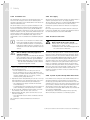
Dimension drawing and connection
dimensions
G 1 1/4
4.3
4
482
49
Ø25
7
Key
1 Wall breakthrough for flue pipe
2 Flue pipe connection
3 Hanging bracket
4 Heating flow
5 Condensate siphon connection
6 Gas connection
7 Heating return
6
5
1
4.4
Requirements for the installation site
4.4.1
Required minimum clearances/installation
clearances
477
70
A
190
2
138
287
3
C
673
680,5
B
960
C
4.2 Recommended minimum clearances/installation clearances
22
Key
A 350 mm (flue pipe diameter 110/160 mm)
450 mm (with cascade design)
B 400 mm
C optional approx. 200 mm
172
172
175
480
> When using the accessories, observe the minimum clearances/installation clearances.
> Where units are installed in cascade, observe the gradient of the flue pipe (approx. 50 mm/m).
603
i
4.1 Connection dimensions in mm
ecoTEC plus installation and maintenance instructions 0020134823_01
When installing the 110/160 mm flue pipe,
observe the minimum clearances in accordance
with ¬ fig. 4.1.
A side gap is not required, however you can remove the
side panels if there is sufficient space at the side
(approx. 200 mm) for maintenance.
It is not necessary to ensure sufficient clearance between
the boiler and combustible materials or components as the
temperature of the boiler will always be less than the maximum permissible temperature of 85 °C due to its nominal
heat output.
15
4 Installation
4.5
Wall-mounting the boiler
a
4.6
Danger!
Risk of death if the load-bearing capacity
of the fixing elements used is insufficient!
If the fixing elements or wall do not have
sufficient load-bearing capacity, the boiler
can come loose and fall down. This may
also cause leaks in the gas line, which is
potentially fatal.
> When installing the boiler, make sure that
the fixing elements have a sufficient
load-bearing capacity.
> Check if the supplied fixing kit may be
used for the wall.
> Check the quality of the wall.
> If required, use individual stands from
the cascade programme which is available as an accessory.
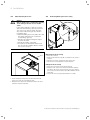
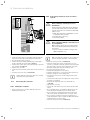
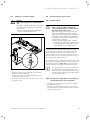
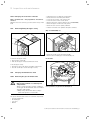
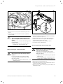
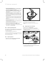
Removing/fitting the front casing
2
1
4.4 Removing the front casing
1
Removing the front casing
> Undo the screw (1)
> Push in both retaining clips (2) so that the front casing is
released.
> Pull the front casing forwards at the bottom edge.
> Lift the front casing upwards from the bracket.
Fitting the front casing
> Place the front casing on the upper brackets.
> Push the front casing onto the boiler until the retaining
clips (2) on the front casing snap into place. For support,
you can also pull the retaining clips (2) downwards at the
same time.
> Secure the front casing by tightening the screw (1).
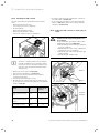
4.3 Wall-mounting the boiler
> Fit the hanging bracket (1) to the wall using the rawl
plugs and screws provided with the unit.
> Hang the boiler (3) on the hanging bracket from above
using the suspension bracket.
16
ecoTEC plus installation and maintenance instructions 0020134823_01
Gas installation 5
5
Gas installation
The work described in this section must only be carried out
by a competent person.
5.1
b
Preparing for installation
a
Danger!
Risk of death caused by improper gas
installation!
An incorrect gas installation may result in
leaks and an explosion.
> During installation, the legal directives
and the local regulations for gas supply
companies must be observed.
a
Danger!
Risk of death caused by improper gas
installation!
Tension in the gas line may result in leaks
or an explosion.
> Make sure there are no stresses in the
gas lines when it is installed.
b
Caution.
Risk of material damage caused by incorrect gas installation.
Excess test pressure may cause damage to
the gas valve.
> When checking the gas valve for leaktightness, use a max. test pressure of
1.1 kPa (110 mbar).
> During the gas installation, ensure that
the home pressure regulation for the
required gas flow pressure of 5 mbar is
maintained in accordance with the technical data (¬ section 18).
b
Caution.
Risk of material damage caused by contaminated lines.
Foreign bodies, such as welding remnants,
sealing residue or dirt in the supply lines
for gas, may cause damage to the boiler.
> Blow the gas line thoroughly clean prior
to installation.
ecoTEC plus installation and maintenance instructions 0020134823_01
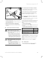
5.2
Caution.
Risk of material damage caused by the
incorrect gas type.
Using the wrong gas type may cause a fault
shutdown on the boiler. Furthermore, ignition and combustion noise may occur in the
boiler.
> Only use the gas type specified in the
type overview (¬ section 1.5).
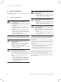
Connecting the gas line
5.1 Gas connection
> Fit an approved gas valve to the unit with a screw
connector.
> Fit the gas supply line to the gas valve.
> Purge the gas line before you start up the unit.
> Check the gas connection for leak-tightness.
17
6 Hydraulic installation
6
Hydraulic installation
The work described in this section must only be carried out
by a competent person.
6.1
b
Caution.
Risk of damage caused by incorrect
installation.
Stresses in the supply line may cause leaks.
> Make sure there is no voltage in the supply lines when they are installed.
b
Caution.
Risk of damage caused by heat transfer
when soldering.
Heat that is transferred during soldering
may cause damage to the seals in the service valves.
> Do not solder the connection pieces if
the connection pieces are screwed to the
service valves.
Preparing for installation
a
Danger!
Risk of personal injury caused by incorrect installation!
Heating water that leaks from the drain line
of the expansion relief valve can cause
severe burns.
> Install the expansion relief valve to
ensure that there is no danger to other
persons.
> Route a discharge pipe with inlet funnel
and siphon on the customer side from
the discharge line of the expansion relief
valve to a suitable drain.
> Make sure that the drain is visible.
Any condensate that occurs must only be fed in under consideration of the local regulations regarding neutralisation.
b
Caution.
Risk of material damage caused by contaminated lines.
Foreign bodies such as welding remnants,
sealing residue or dirt in the water pipes
may cause damage to the boiler.
> Flush the heating installation thoroughly
prior to installation.
b
Caution.
Risk of damage from corrosion.
If non-diffusion-tight plastic pipes are used
in the heating installation, this may cause
air to enter the heating water and corrosion
of the heat generation circuit and the
boiler.
> If using non-diffusion-tight plastic pipes
in the heating installation, separate the
system by installing an external heat
exchanger between the boiler and the
heating installation.
18
a
Danger!
Risk of scalding and/or damage due to
leaking water.
Stresses in the supply line may cause leaks.
> Make sure there is no voltage in the supply lines when they are installed.
The Vaillant ecoTEC boiler should be connected using a
Vaillant pump group with modulating pumps (available as
an accessory).
This pump group has a connection option for an expansion
vessel (right-hand connection) and an expansion relief valve
(left-hand connection). You can also purchase these as
accessories.
> When installing the pump group, observe the installation
sequence for the insulation and the hydraulic pipes
(¬ pump group installation instructions).
> Note that the boiler pump must always be fitted in the
return line. Otherwise, this may lead to a unit fault.
When connecting several units in cascade operation, you
must install a non-return flap from the cascade connection
set for each individual unit in the unit supply.
A non-return flap from a third-party manufacturer must
have no more than 30 mbar pressure losses for a volume
flow of 4.5 m3/h.
ecoTEC plus installation and maintenance instructions 0020134823_01
Hydraulic installation 6
6.2
Connecting the heating flow and heating
return
b
Caution.
Risk of material damage caused by incorrect installation.
Stresses in the supply line may cause leaks.
> Make sure there is no voltage in the supply lines when they are installed.
b
Caution.
Risk of damage to the service valves.
> Do not solder the connection pieces if
the connection pieces are screwed to the
service valves.
i
Seals made of rubber-like materials may be subject to plastic deformation, which may lead to
pressure losses.
We recommend using seals made of a paste-like
fibre material.
Hydraulic connection
For connection to the system a hydraulic header has to be
used. In difficult cases a plate to plate heat exchanger is
recommended. In all instances the system water should be
adequately treated.
To this end, various plate heat exchangers are available as
accessories, depending on the output of a unit or in cascade connection. The pressure loss is adjusted to the pump
group that is offered as an accessory. The minimum volume
of circulating water is guaranteed in the unit circuit thanks
to the original plate heat exchangers and pump groups, provided the maximum pressure losses are not exceeded in the
piping.
To prevent contamination, it is recommended that you
install a dirt filter when using plate heat exchangers. This
prevents excessive contamination of the heat exchanger.
Back-purging devices for cleaning the plate heat exchanger
are to be placed on-site.
Ø 1 1/4"
6.2 Diameter of the supply lines
1
The following remaining feed heads are available at the unit
supply:
6.1 Installing the heating flow and heating return
Power
Description
> Insert a flat gasket in each.
> Screw the service valves onto the flow and return connection (1) of the pump group.
> Screw the service valves to the customer's installation.
The diameter of the line is 1 1/2".
80 kW
Modulating pump
100 kW
Modulating pump
120 kW
Modulating pump
Remaining feed
head
0.042 MPa
(420 mbar)
0.026 MPa
(260 mbar)
0.024 MPa
(240 mbar)
6.1 Remaining feed head pump group
If you are using a plate heat exchanger to hydraulically separate the system, the following pressure losses must be
maintained:
ecoTEC plus installation and maintenance instructions 0020134823_01
19
6 Hydraulic installation
Power
Max. pressure
loss (mbar)
< 120 kW
86
in conjunction with the hydraulic cascade
< 240 kW
96
< 360 kW
76
< 480 kW
82
< 600 kW
87
< 720 kW
92
6.2 System separation pressure loss
6.3
min.
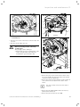
180
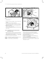
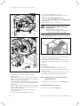
Connecting the condensate drain pipework
1
2
a
a
Danger!
Risk of death from escaping flue gases!
An empty or insufficiently filled condensate
siphon may allow flue gases to escape into
the room air.
> Make sure that the condensate siphon is
filled with water when switching on the
boiler.
Danger!
Risk of death from escaping flue gases!
If the condensate drain pipework is connected tightly to a fixed connection on the
waste-water piping, the internal condensate
siphon can be fully drained until empty.
> Do not connect the condensate drain
pipework tightly to the waste-water
piping.
> It is recommended that the condensate
is drained into a tundish. The condensate
drain is totally sealed. It may be possible
to empty the trap due to syphonic action
causing leackage of combustion
products:
Condensate forms in the boiler during combustion. The condensate drain pipework routes the condensate to the waste
water connection via a tundish.
The boiler is equipped with a condensate siphon. The filling
height is 145 mm. The condensate siphon collects any condensate that occurs and feeds it into the condensate drain
pipework.
3
6.3 Condensate siphon
Install the enclosed condensate siphon as follows:
> Place the condensate siphon on the underside of the
boiler on the condensate drain pipe and secure it using
the retaining clips.
> Leave an installation space of at least 180 mm beneath
the condensate siphon so that you can clean the condensate siphon in the case of service work.
> Check the connection for leaks.
> Check if a neutralising unit is required in accordance
with national regulations.
To connect the condensate drain pipework, proceed as
follows:
> Hang the condensate drain pipework of the boiler in the
pre-installed tundish.
> If required, guide the drain hose (1) of the automatic air
vent into the tundish.
i
The condensate drain pipework connected to the
condensate discharge of the boiler must have a
downward gradient throughout its entire length
(45 mm per metre) and should be installed and
connected within the building to prevent possible freezing.
> The connections for the condensate drain pipework must
not be modified or blocked
> The condensate drain pipework must terminate in a suitable location.
Further information can be obtained from "BS 6798 Specification for installation of gas-fired boilers of rated input not
exceeding 70 kW net". Before the boiler is started up, the
condensate siphon (1) must be filled with water as
described in the relevant section.
20
ecoTEC plus installation and maintenance instructions 0020134823_01
Hydraulic installation 6
6.4
Connecting the discharge pipe to the
expansion relief valve on the heating
installation
The expansion relief valve for the heating installation can
be connected to the pump group (left-hand side)
> Install the drain line for the expansion relief valve so that
it is not damaged when removing and fitting the lower
part of the condensate siphon.
i
We do not recommend shortening the discharge
pipe that is supplied.
> Leave an installation space of at least 180 mm beneath
the condensate siphon.
1
2
min.
180
3
6.4 Install the discharge pipe on the expansion relief valve
> Insert a seal (1) in the cap nut (2).
> Screw the discharge pipe (3) onto the expansion relief
valve.
> Make the drain line routing as short as possible and in a
downward gradient away from the boiler.
> Allow the line to terminate in such a way that nobody
can be injured and no cable or other electrical components can be damaged if water or steam is ejected.
> Please note that the end of the line must be visible.
ecoTEC plus installation and maintenance instructions 0020134823_01
21
7 Flue gas installation
7
Flue gas installation
7.2
Installing the flue pipe
> Install the flue pipe using the enclosed installation
instructions.
7.1
Preparing for installation
a
Danger!
Risk of personal injury and material damage due to unapproved flue pipes.
Vaillant boilers are certified only with genuine Vaillant flue pipes. The use of other
accessories may cause personal injury and
material damage as well as operating faults.
> Only use genuine Vaillant flue pipes.
i
You will find a list of genuine flue pipes in the
Vaillant installation instructions for flue pipes.
All ecoTEC plus boilers feature an 110/160 mm diameter air/
flue gas connection as standard. Selecting the most suitable system depends on the individual installation and application conditions.
> When installing the flue pipe, observe the provisions of
the applicable national regulations.
> Agree the flue pipe with your chimney sweep.
> Lay the flue pipe with a downward gradient so that any
escaping condensate can easily flow into the drain
(siphon) provided for it without leaving any backwater
residues.
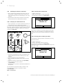
7.1 Installation example: Vertical roof duct
7.3
Flue gas guiding opening
The following information applies to all flue pipe systems.
a.
The terminal must be positioned so that the products
of combustion can disperse freely at all times.
b.
Water vapour will sometimes be visible from the terminal of the flue gas system. Fitting locations where
this could be a nuisance should be avoided.
c.
If the terminal is installed less than 2 m above a balcony, above ground or above a flat roof to which people have access, a suitable terminal guard must then
be provided and fitted (contact Tower Flue Components, Tonbridge, TN9 1TB).
i
Vertical flues must not terminate within 600 mm
of an openable window, air vent or any other
ventilation opening.
The flue gas system must be attached or shielded in such a
way that ignition (causing fire) or damage to any part of the
building is avoided.
22
ecoTEC plus installation and maintenance instructions 0020134823_01
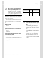
Flue gas installation 7
P
B
Q
Q
B
A
C
D,E
B
C
2m
H E
A
S
M
H
H
N
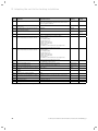
7.2 Opening of the flue pipe
Installation site
Minimum
dimensions
Horizontal flue gas pipes
A
B(5)
C
D
E(4)
F
G(4)
H
H(2)
J
J(2)
L
M
N
Directly below an opening, air bricks, opening
windows, etc.
Above an opening, air bricks, opening windows,
etc.
Horizontally to an opening, air bricks, opening
windows, etc.
Below temperature-sensitive building components e.g. plastic gutters, down pipes or wastewater pipes
Below eaves, adjacent to wastewater pipes
Below balconies or car port roofs
From a vertical wastewater pipes or down pipes
From internal or external corners
From the edges along to a terminal/outside
corner
Opposite an edge or a terminal
From a surface facing a terminal
From an opening in the car port (e.g. door,
window) which leads into the dwelling
Vertical from a terminal
Horizontal from a terminal
Vertical flue gas pipes
P
From another terminal
Q Above the roof area
R(3) From adjacent windows that cannot be opened
S(2) From an adjacent wall to the flue gas pipe
(5)
(6)
The flue through the roof should not be located within the
shaded area.
Is is recommended that the terminal should not be located
below 2 m in any occupied space.
600 mm
600 mm
600 mm
25 mm
50 mm (1)
25 mm
50 mm
50 mm
300 mm
2000 mm
1000 mm
N/A
1500 mm
600 mm
BS 5440–1: It is recommended that the fanned flue terminal
should be positioned as follows:
– at least 2 m from an opening in the building directly
opposite, and
– so that the products of combustion are not discharged
directly across a property boundary.
– Dimensions D, E and F:
These clearances may be reduced to 25 mm without
affecting the performance of the boiler. In order to
ensure that the condensate vapour plume does not damage adjacent surfaces, the terminal should be extended
as shown in ¬ fig. 7.3.
– Dimension H:
This clearance may be reduced to 25 mm without
adversely affecting the performance of the boiler. However, in order to ensure that the condensate vapour
plume does not damage adjacent surfaces, a clearance
of 300 mm is preferred.
For IE, recommendations are given in the current issue
of the IS 813.
600 mm
600 mm
1000 mm
300 mm
Balcony/eaves
7.1 Position of the opening of a fan-assisted flue gas guiding
Gutter
Key:
(1)
There should be no ventilation/opening in the eaves within
600 mm distance of the terminal.
(2)
These dimensions comply with the building regulations, but they
may need to be increased to avoid wall staining and nuisance
fron pluming depending on site conditions.
(3)
It is recommended that an elbow termination is fitted to direct
the plume away from windows.
(4)
If the pipe is shielded from the heat this dimension may be
reduced to 25 mm.
ecoTEC plus installation and maintenance instructions 0020134823_01
Adequately secured
air/flue gas pipe
The flue pipe must
protrude beyond any overhang
7.3 Opening of the flue gas system under balconies or eaves
23
8 Electrical installation
8
Electrical installation
The work described in this section must only be carried out
by a competent person.
8.1
8.2
Opening/closing the electronics box
> Remove the front casing of the boiler (¬ section. 4.6).
Preparing for installation
2
e
e
24
Danger!
Risk of death from electric shock!
Touching live connections may cause serious personal injury.
> Switch off the power supply.
> Secure the power supply against being
switched on again by unauthorised persons while you are working on the boiler.
Danger!
Risk of death from electric shock as a
result of an improper electrical
connection!
An improper electrical connection may
adversely affect the operational safety of
the boiler and result in material damage or
personal injury.
> The electrical installation must be carried out by a suitably qualified competent person who is responsible for complying with the existing standards and
directives.
> Connect the boiler in accordance with
BS 7671 (IEE Regulations).
> For IE: Observe the current ETCI regulations (Electro Technical Council for
Ireland).
> Earth the boiler.
1
3
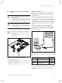
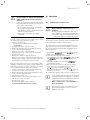
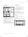
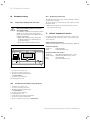
8.1 Opening the back wall of the electronics box
> Tilt the electronics box (1) forwards.
> Loosen the clips (3) from the brackets.
> Tilt the cover (2) upwards.
Closing the electronics box
> Close the cover (2) by pushing downwards on the electronics box (1).
> Ensure that all clips (3) audibly click into the brackets.
> Tilt the electronics box upwards.
> Push the four right and left clips of the box against the
side panels on the boiler until you hear them click into
place.
> Attach the front casing of the boiler (¬ section 4.6).
8.3
Establishing the mains connection and
connecting the pump group
e
Danger!
Risk of death from electric shock!
Mains connection terminals L and N remain
permanently live even if the boiler on/off
button is switched off!
> Before establishing the mains connection, switch off the power supply.
b
Caution.
Risk of material damage caused by the
incorrect supply voltage!
At mains voltages greater than 253 V and
less than 190 V, the functions may be
impaired.
> Make sure that the rated voltage of the
mains is 230 V.
ecoTEC plus installation and maintenance instructions 0020134823_01
Electrical installation 8
b
b
Caution.
Risk of damage caused by incorrect
installation.
Mains voltage at the incorrect plug terminals on the ProE system may destroy the
electronics.
> Only connect the mains connection cable
to the terminals marked for the purpose.
> Use a flexible connection cable.
Caution.
Risk of damage caused by incorrect
installation.
Connecting wires that have been stripped
too far may cause short circuits and damage the electronics if a strand accidentally
comes loose.
> Only strip the lines a maximum of 3 cm
to prevent short circuits.
> Lay the lines correctly.
> Use strain reliefs.
In IE, reference should be made to the current edition of
the ETCI (Electro-Technical Council for Ireland) rules.
The boiler is supplied for connection to 230 V, ~ 50 Hz supply fused at 3 A. The connection to the supply network is
made using a 3 A fused double-pole isolator with a contact
opening of at least 3 mm at all poles. A prerequisite here is
that only the boiler and controllers are connected). At the
connection point to the mains, it must be possible to completely isolate the boiler and its auxiliary controllers electrically. The connection should be easily accessible and adjacent to the boiler. Use a three-core flexible cable in accordance with BS 6500, tables 6, 8 or 16
(3 x 0.75 to 3 x 1.5 mm2).
The rated voltage of each line in the mains must be 230 V;
with mains voltages over 253 V and below 190 V, the unit
may not function properly.
> Open the electronics box (¬ section 8.2).
> Use a flexible, commercial mains connection cable that is
compliant with standards.
> Guide the mains connection cable through the cable duct
on the left of the base of the unit.
> Use the grommet supplied to seal the cable duct.
ecoTEC plus installation and maintenance instructions 0020134823_01
L N
230V~ 230V~
L N
230V~ 230V~
8.2 Cable routing of the mains connection cable
> Insert the mains connection cable into the electronics
box.
> Uses the strain reliefs provided.
> Shorten the flexible mains connection cable as necessary.
> Strip the flexible mains connection cable by 2-3 cm, but
not more than 3 cm.
> Insulate the conductor of the flexible mains connection
cable.
> Fit conductor end sleeves on the stripped ends of the
conductors.
> Connect the provided green ProE plug for the mains connection to the flexible mains connection cable using a
screwdriver.
> Insert the ProE plug into the corresponding PCB slot
(L, N and earth) (¬ fig. 8.2).
> Lay the lines correctly.
> Secure the cable in the electronics box using the strain
reliefs.
> Close the electronics box (¬ section 8.2).
i
Ensure that the connection cables are securely
fastened to the plug terminals.
25
8 Electrical installation
X22
X18
230 V
8.4.2 Connecting controllers to the electronic
system
b
Caution.
Risk of damage caused by incorrect
installation.
Connecting wires that have been stripped
too far may cause short circuits and damage the electronics if a strand accidentally
comes loose.
> Only strip the lines a maximum of 3 cm
to prevent short circuits.
> Lay the lines correctly.
> Use strain reliefs.
b
Caution.
Risk of material damage caused by incorrect installation.
Mains voltage at the incorrect plug terminals on the ProE system may destroy the
electronics.
> Do not connect a mains voltage to the
eBUS terminals (+/-).
i
Make sure that the conductors are securely fastened to the plug terminals of the ProE plug.
8.3 Connecting the pump group to the PCB
> Guide the pump cable for the pump group through the
cable duct to the right on the underside of the unit.
> Uses the strain reliefs provided.
> Connect the power supply network plug of the pump
group to the X18 slot on the PCB (¬ fig. 8.3).
> Connect the control cable of the pump group to the X22
slot on the PCB (¬ fig. 8.3).
> Lay the lines correctly.
> Secure the lines using the strain reliefs in the electronics
box.
> Close the electronics box (¬ section 8.2).
i
8.4
8.4.1
Ensure that the connection cables are securely
fastened to the plug terminals.
Connecting the controller
Fitting the controller
> Fit the controller in accordance with the respective
installation instructions.
26
> Open the electronics box (¬ section 8.2).
> Guide the supply lines of the components to be connected (e.g. external controller, external sensor) through
the cable duct to the left on the underside of the unit.
> Insert the supply lines into the electronics box.
> Uses the strain reliefs provided.
> Shorten the supply lines as necessary.
> Strip the supply lines 2 - 3 cm, but not more than 3 cm.
> Strip the conductor on the supply lines.
> Fit conductor end sleeves on the stripped ends of the
conductors.
> Connect the ProE plug to the supply lines of the controller using a screwdriver.
> Insert the ProE plug into the associated PCB slot
(¬ fig. 8.4).
> Lay the lines correctly.
> Secure the cable in the electronics box using the strain
reliefs.
> If you do not connect a room/timer thermostat to the
boiler, bridge the input RT 24 V if no bridge exists.
> If you connect a room/timer thermostat to the boiler,
remove the bridge at input RT 24 V, if a bridge exists.
> If you connect a weather-controlled compensator or
room temperature control system via eBUS, then bridge
input RT 24 V, if no bridge exists.
> Close the electronics box (¬ section 8.2).
ecoTEC plus installation and maintenance instructions 0020134823_01
Electrical installation 8
> In order to achieve pump operating mode 1 "Comfort"
(continuously running pump) for multi-circuit controllers,
set the diagnostics code D.018 Pump operating mode
from 3 = "Eco" (intermittent pump) to 1 = "Comfort"
(¬ section 12.1.2).
> If the system partition is installed, set the pump to Comfort (D.018) and set the pump output to at least 4 (85 %,
D.014). The same setting applies for installing units in
cascade.
i
8.5
> For smooth operation in cascade, use the diagnostics
code D.050 to raise the fan speed in partial load operation to 1500 rpm.
Please note that the bridge at the ProE plug
must be removed when connecting a maximum
thermostat (contact thermostat) for underfloor
heating.
Connecting additional units
b
8.5.1
For cascade operation according to the B23p configuration,
you must provide a motorised flue non-return flap for each
unit and this is actuated by the VR 40 multi-functional
module.
The installation instructions for the VR 40 describe how the
flue non-return flap is activated.
Caution.
Risk of damage caused by incorrect
installation.
Connecting wires that have been stripped
too far may cause short circuits and damage the electronics if a strand accidentally
comes loose.
> Only strip the lines a maximum of 3 cm
to prevent short circuits.
> Lay the lines correctly.
> Use strain reliefs.
VR 40 - Connecting the "2 from 7" multifunctional module
You can connect two additional components to the ecoTEC
plus using the Vaillant multi-functional module "2 from 7"
(Accessories).
You can switch the following components:
– Circulation pump
– External pump
– Cylinder charging pump
– Fume extractor hood/flue non-return flap
– External solenoid valve
– External fault signal
– Not active
– Remote control eBUS (not active)
– Anti-legionella pump (not active)
> Install the components in accordance with the respective
installation instructions.
> Select diagnostics code D.018 to actuate relay 1 on the
multi-functional module at installer level (¬ section 12.1).
> Select diagnostics code D.028 to actuate relay 2 on the
multi-functional module at installer level (¬ section 12.1).
ecoTEC plus installation and maintenance instructions 0020134823_01
27
8 Electrical installation
Connection wiring diagram
Display
connection
Pump PWM signal
blue
Gas valve
Water
pressure sensor
Cylinder sensor (optional)
white
white
Cylinder contact
“C1-C2“
Flow sensor
blue
Flow sensor
pink
red
Water
DD
Safety
cut-out
Remote control circulation pump
External sensor
Flow sensor (optional)
DCF connection
Earth
Earth
Contact thermostat/burner off
Accessory output
(Select via D.26)
PWM
Earth
Bus connection
(Controller(room th. digital)
grey
pink
Ext. room th. 3-4 (contact, 24 V)
pink
white blue
Edge connector
Safety
cut-out
Flue gas
DD
Hall signal
8.6
Fan
blue
Charging pump
turquoise
white
green
internal pump
Ext. ignition transformer (supply)
Ioni. signal
Unit earth
Mains connection
Unit earth
8.4 Connection diagram for the ecoTEC plus electronics box
28
ecoTEC plus installation and maintenance instructions 0020134823_01
Establishing operational readiness 9
9
Establishing operational readiness
The Vaillant ecoTEC plus boiler is fitted with a digital information and analysis system (DIA). If additional settings are
required, which have not been configured using the installation assistant, you can view and modify further parameters
using the DIA.
The operating concept and operation of the boiler are
described in the ¬ Operating instructions of the boiler. The
read-off and setting facilities of the operator level are also
described in the ¬ Operating instructions.
9.1
Reading the temperature or pressure
display
Press the right-hand selection button twice to read off the
digital filling pressure value.
9.2
Observe the specifications concerning heating water preparation in (¬ section 2.4.5).
9.3
Filling and purging the heating installation
b
Left-hand button
: Hot water handling ¬ Cylinder
temperature
: Heating mode ¬ Heating
Right-hand button
temperature/water pressure
50
Preparing the heating water
Caution.
Risk of material damage caused by contaminated lines!
Foreign bodies, such as welding remnants,
sealing residue or dirt in the water pipes,
may cause damage to the boiler. It is recommended that you use a dirt trap on older
systems upstream of the ecoTEC plus.
> Thoroughly flush newly installed part of
the heating installation prior to start-up.
The system is filled via a filling connection installed on-site,
which must be fitted at a suitable location in the heating
circuit. This connection must be removed again after the
filling process is complete. If the local water authority does
not permit temporary connections you must use a closed
system filling pump with an interrupt vessel. Automatic filling of the heating system does not take place from the hot
water side. (Alternative procedures for filling closed systems are described in BS 5449).
To ensure the correct operation of the heating installation,
the indicator on the pressure gauge must point to the
upper half of the grey area or in the middle of the bar
graph display (marked by the dashed limit value) when the
heating installation is cold. This corresponds to the filling
pressure between the minimum and maximum recommended pressure. You can also display the exact filling
pressure.
> Flush the newly installed part of the heating installation
thoroughly before filling it.
> Open all thermostatic radiator valves in the heating
installation.
> Select check programme P.6 (¬ section 11.4).
The check programme starts, the burner and pump are
switched off (to fill or drain the boiler).
9.1 Reading the temperature or pressure display
The boiler is fitted with an analogue pressure gauge and
also has a symbolic bargraph display for the fill pressure of
the heating installation and a digital pressure and temperature display.
You can see the pressure gauge once you have removed
the front casing of the boiler.
ecoTEC plus installation and maintenance instructions 0020134823_01
9.3.1
Filling the heating installation
> Connect a hose between a cold water valve and the filling line of the heating system.
> In order to fill the heating installation, first open the cold
water valve.
> Open all thermostatic radiator valves.
29
9 Establishing operational readiness
> Check that both service valves on the boiler are open.
> Slowly open the stop valve on the filling line so that the
water flows into the heating system.
9.3.3 Flush the heating installation for the first
time ("cold")
i
i
If the water pressure in the heating system is
too low, the display view switches between fault
message F.22 and the display of the actual pressure when the boiler is switched on.
> Purge the lowest radiator until water flows out of the
purging valve without bubbles.
> Purge all other radiators until the entire heating system
has been filled with water. Close all purging valves.
> Use the display to monitor the rising filling pressure in
the heating installation.
> Top up with water until the pressure gauge display is in
the middle of the grey area and the required filling pressure appears on the display.
> After filling, close the stop valve on the filling line as well
as the cold water valve and remove the filling hose.
> Check all connections and the entire system for leaks.
> Each time the unit is filled and topped up, document this
in a system book.
i
Ensure that the filling and drainage tap in the
heating installation is connected to a cold water
valve in accordance with the standard.
The complete heating system must be flushed at
least twice: once with cold water and once with
hot water in accordance with the following
instructions.
> Check whether all thermostatic radiator valves and both
service valves on the boiler are open.
> Connect a hose to the drain valve that is located at the
lowest position in the heating system.
> Fully open the radiator valves and drain cocks to ensure
that the water drained quickly. Starting at the top of the
system open the air vents on the radiators to aid complete draining of the contaminated water.
> Close the drain cocks.
> Refill the heating system with water, as described in
(¬ section 9.3).
> Check that the expansion relief valve of the heating system is functioning correctly by turning the handle on the
valve.
> Check the pressure in the heating system and top up
with water if necessary.
> Close the filling valve and the cold water valve.
9.4
Preventing low water pressure
9.3.2 Purging the heating installation
> To purge the heating installation, select check programme P.0 (¬ section 11.4).
The boiler does not start up, the internal pump operates
intermittently and, as an option, purges the heating circuit
or the hot water circuit. The display shows the filling pressure of the heating installation.
To prevent damage to the heating installation that is caused
by low water pressure, the boiler is fitted with a water pressure sensor. If the water pressure falls below 0.1 MPa
(1.0 bar), the boiler indicates low pressure by displaying a
flashing pressure value. If the water pressure falls below
0.05 MPa (0.5 bar), the boiler switches off. The display
shows F.22.
> Top up the heating water and switch the boiler on again.
> The filling pressure of the heating installation must not
fall below 0.08 MPa (0.8 bar) when purging is in progress
as, otherwise, this will not be carried out properly.
Check programme P.0 runs for 6.5 minutes.
> Purge all the radiators.
> Then check the water pressure in the heating installation
again.
At the end of the filling procedure, the filling pressure of
the heating installation should be at least 0.02 MPa
(0.2 bar) above the counterpressure of the expansion vessel
("Exp") (PInstallation PExp + 0.02 MPa (0.2 bar)).
> If there is still too much air in the heating installation at
the end of check programme P.0, repeat the check programme.
> Check all connections for leak-tightness.
30
A flashing pressure value appears on the display until a
pressure of 0.11 (1.1 bar) or higher has been reached.
> If you notice frequent drops in pressure, then determine
and eliminate the cause.
ecoTEC plus installation and maintenance instructions 0020134823_01
Establishing operational readiness 9
9.5
Filling the condensate siphon
a
Danger!
Risk of poisoning due to escaping flue
gas.
An empty or insufficiently filled condensate
siphon may allow flue gas to escape into
the room air.
> Fill the condensate siphon with water
before starting up the boiler.
9.6
Checking the gas ratio setting
9.6.1
Default setting
b
Caution.
An incorrect gas-family setting can
cause operating faults or a reduction in
the working life of the boiler!
If the unit design does not correspond to
the locally available gas family, you will
experience error functions or you will have
to replace boiler components prematurely;
for example, a liquid-gas boiler must not be
operated with natural gas.
> Before starting up the boiler, compare
the details concerning the set type of gas
on the identification plate with the type
of gas supply at the installation site.
If the unit should be operated with liquid gas (propane), do
not start up the unit. Instead, contact Vaillant Customer
Service. They will convert the unit and then start it up.
The same applies for the conversion from liquid gas (propane) to natural gas. This conversion must also only be carried out by Vaillant Customer Service.
1
2
9.2 Filling the condensate siphon
> Remove the siphon lower section (2) by unscrewing it
from the condensate siphon (1).
> Fill the siphon lower section with water up to about
10 mm below the upper edge.
> Secure the siphon lower section correctly to the condensate siphon again.
The combustion of the ecoTEC plus has been factory tested
and is preset for operation with the gas group indicated on
the identification plate (¬ table 13.1). In some areas these
settings may need to be adjusted at the installation site.
i
It is not necessary to check the gas volume during initial start-up. The adjustment takes place
based on the CO2 component in the flue gas. The
gas ratio setting must be defined in the attached
commissioning checklist.
9.6.2 Checking the leak-tightness of the flue gas
system and for flue gas recirculation
> Check that the flue gas system is intact, in accordance
with British Gas TB 200.
> If the flue gas system is longer than 2 m, we urgently
recommend that you test the system for flue gas recirculation as described below.
ecoTEC plus installation and maintenance instructions 0020134823_01
31
9 Establishing operational readiness
1
806/5-5
1
9.3 Flue gas and air analysis points
Key:
1 Flue gas analysis point
2 Air analysis point
> Use the air analysis point (2) to check for flue gas recirculation.
> Use the flue gas measuring instrument.
> If you discover CO or CO2 in the fresh air, search for a
leak in the flue gas system or for flue gas recirculation.
> Eliminate the damage.
> Repeat the above-mentioned test to determine if the
fresh air contains CO or CO2.
> If you cannot eliminate the damage, you must not start
up the boiler.
9.6.3 Checking the gas connection pressure
(gas flow pressure)
> Ensure that the gas connection pressure (gas flow pressure) can be still achieved if all other gas-fired boilers in
the dwelling/house are in operation.
> Remove the front casing from the boiler (¬ section 4.6).
> Close the gas isolator cock of the boiler.
i
32
Permissible gas connection pressure (gas flow
pressure) for natural gas operation:
2 kPa (20 mbar) to 2.5 kPa (25 mbar)
1006/5-5
1206/5-5
1
9.4 Measuring the gas connection pressure (gas flow pressure)
> Undo the sealing screw of the measuring nipple (1)
(lower screw) at the gas valve using a screwdriver.
> Connect a digital pressure gauge or U tube manometer
to the measuring nipple (1).
> Open the gas isolator cock of the boiler.
> Start the boiler by activating check programme P.1, as
described in ¬ section 14.4.
> Turn the room thermostat fully up to that the maximum
heat in the heating installation can be shown.
> Measure the gas connection pressure in comparison with
atmospheric pressure.
ecoTEC plus installation and maintenance instructions 0020134823_01
Operation 10
b
Caution.
Possible material damage and operating
faults caused by incorrect connection
pressure.
If the gas connection pressure lies outside
the permissible range, this can cause operating faults on the boiler.
> Do not make any settings on the boiler.
> Do not operate the boiler.
> Check the pressure control system at the
entrance to the property.
> Advise the responsible gas supply
company.
If the gas connection pressure (gas flow pressure) is within
the permissible range, proceed as follows:
> Switch off the boiler by:
– Ending check programme P.1 as described in
¬ section 11.4.
> Close the gas isolator cock of the boiler.
> Remove the pressure gauge and tighten the sealing
screw of the measuring nipple (1).
> Open the gas isolator cock of the boiler.
> Ensure that there are no leaks at the sealing screw.
> Refit the front casing.
> Reset boiler controls for normal operation.
> Make a note of the gas connection pressure (gas flow
pressure) (kPa or mbar) of the boiler in the commissioning checklist for starting up the gas-fired boiler.
If the gas connection pressure (gas flow pressure) is not
within the permissible range and you cannot eliminate the
fault, please notify the gas supply company or the Vaillant
Service Solutions Team, and proceed as follows:
> Switch off the boiler by ending check programme P.1.
> Close the gas isolator cock of the boiler.
> Remove the pressure gauge and re-tighten the sealing
screw of the measuring nipple (1).
> Open the gas isolator cock.
> Ensure that there are no leaks at the sealing screw.
> Turn the gas isolator cock off.
> Refit the front casing.
> Disconnect the power supply to the boiler.
> You must not start up the boiler yourself.
ecoTEC plus installation and maintenance instructions 0020134823_01
10
10.1
Operation
Calling up the installer level
b
Caution.
Risk of damage caused by incorrect
handling.
Incorrect settings at installer level can
cause damage to the heating installation.
> You must only access the installer level if
you are an approved competent person.
The following overview shows the options for reading information and making settings at installer level.
The installer level is secured against unauthorised access
with a password because incorrect parameter settings at
this level may cause functional faults and damage to the
heating installation.
and right
selection
> Press the left
buttons ("i") simultaneously
The following menu appears on the display.
or the plus but> Scroll using the minus button
until the menu point "Installer level"
ton
appears.
to
> Press the right-hand selection button
select the menu point.
"Enter code" and the value "00" appear in the display.
> Select the value 17 (code) using the minus button
or the plus button
.
to con> Press the right-hand selection button
firm the entered code.
The installer level appears with a selection of menu points.
i
At the installer level the path to access the Fault
list, Test Programmes, the Appliance Configuration, Diagnosis Menue and Installation Assist are
outlined in the following overview, e.g.
Menu ¬ Installer level ¬ Test programmes ¬
Check programmes.
i
If you exit the installer level and then access it
again within 15 minutes, you do not have to
enter the code again.
33
10 Operation
10.2
Overview of the menu structure
Menu
Information
Reset burner off time
Installer level
Back
Select
Installer level
Fault list
Test programs
Appliance config.
Enter code
17
Back
OK
Back
Select
Installer level
Fault list
Test programs
Appliance config.
Back
Select
F.00
F.75
Interruption
Fault
Flow sensor
Pump water shortage
Test programs
Check programs
Gas type check
Function menu
Back
Select
Test programs
Check programs
Gas type check
Function menu
Back
Select
Test programs
Gas type check
Function menu
Self test electronics
Back
Select
Test programs
Gas type check
Function menu
Self test electronics
Back
Installer level
Test programs
Appliance config.
Diagnosis menu
Back
Select
Select
Appliance config.
Language
Target flow temp.
DHW temperature
Back
Select
Appliance config.
Language
Target flow temp.
DHW temperature
Back
Select
Appliance config.
Language
Target flow temp.
DHW temperature
Back
Select
P.00 Purging
P.00 Purging
Pump is
Pump is
cyclically
cyclically
actuated
actuated
Back
Select
Back
Select
Gas type check
Type of gas
LPG
Select
Back
Select
T.01
T.01
internal pump
internal pump
Back
Back
Select
Select
Self test
Self diagnosis
of the electronics
Back
Select
Language
01 Deutsch
Cancel
OK
Target flow temp.
41
Cancel
OK
DHW temperature
35
Cancel
OK
10.1 Overview of the menu structure for installer level, part 1
34
ecoTEC plus installation and maintenance instructions 0020134823_01
Operation 10
Appliance config.
Target flow temp.
DHW temperature
Comfort mode
Back
Select
Appliance config.
DHW temperature
Comfort mode
Auxiliary relay
Back
Select
Appliance config.
Comfort mode
Auxiliary relay
Accessory relay 1
Back
Select
Appliance config.
Auxiliary relay
Accessory relay 1
Accessory relay 2
Back
Select
Appliance config.
Accessory relay 1
Accessory relay 2
Heating partial load
Back
Select
Appliance config.
Accessory relay 2
Heating partial load
Contact data
Back
Select
Appliance config.
Heating partial load
Contact data
Factory setting
Back
Installer level
Test programs
Appliance config.
Diagnosis menu
Back
Select
Installer level
Appliance config.
Diagnosis menu
Start inst. assistant
Back
Select
Select
Comfort mode
Comfort on
Cancel
OK
D.026
D.026
Auxiliary relay
Auxiliary relay
Circulation pump
External pump
Back
Cancel
OK
D.027
D.027
Accessory relay 1
Accessory relay 1
Circulation pump
External pump
Back
Cancel
OK
D.028
D.028
Accessory relay 2
Accessory relay 2
Circulation pump
External pump
Back
Cancel
OK
D.000
Heating partial load
0
Cancel
OK
Contact data
Phone number
Back
D.096
Reset to
factory settings?
No
Cancel
OK
D.000
D.001 partial load
Heating
Pump overrun
Heating
0
0
Back
Back
To start the Installation assist.
press OK
Cancel
OK
10.2 Overview of the menu structure for installer level, part 2
ecoTEC plus installation and maintenance instructions 0020134823_01
35
11 Start-up
11
Start-up
a
i
i
Danger!
Risk of poisoning and scalding caused by
escaping hot flue gases.
Hot flue gas may escape and cause poisoning and scalding, if the boiler is operated
with an incompletely fitted or open flue
pipe or if the boiler is operated with the
front casing open in the event of internal
leaks.
> Operate the boiler
- for start-up
- for testing
- in continuous mode
only when the front casing is closed and
the flue pipe is fully installed and closed.
Initial start-up is performed by a Vaillant customer service engineer or by a competent person approved by Vaillant. The appliance must be
comissioned by a competent person who is in
possession of a calibrated gaz analyser. Initial
start-up is performed in accordance with the
commissioning checklist and is also acknowledged there by the approved competent person.
The commissioning checklist that is attached to
the installation instructions must be filled out
and carefully stored with the unit's
documentation.
Before filling the heating circuit and during further operation, the cap of the automatic air vent
must be open.
To purge the heating circuit, use purging programme "P.0" (¬ section 11.4).
lation assistant is displayed each time the boiler is switched
on until it has been completed successfully.
You must confirm the launching of the installation assistant.
Once confirmed, all of the heating and process water
demands from the boiler are blocked. This status remains
until the installation assistant is completed or cancelled.
If you do not confirm the launch of the installation assistant, it is closed 10 seconds after you switch on the unit and
the basic display then appears. The next time the boiler is
switched on using the on/off button, the installation assistant will be started again.
11.2.1
Language
> Select the required language using the minus or plus
button.
> Press the right-hand selection button to confirm the
selected language.
The language change must be confirmed a second time in
order to avoid an unintentional change.
i
If you unintentionally select a language that you
cannot understand, you can change it again as
described below.
> Press the right-hand selection button and the plus button simultaneously and hold them down.
> Press the fault clearance key for a short time.
> Continue to press and hold the right-hand selection button and the plus button until the display offers you the
option to set the language.
> Use the minus button or plus button to select your
desired language.
> Confirm the change by pressing the right-hand selection
button ("OK").
11.2.2 Purging
Auxiliary service equipment:
The following test and measuring equipment is required for
start-up:
– Calibrated CO2-measuring instrument
– Digital or U tube manometer
> Fill the heating circuit slowly and purge the boiler via the
purging device fitted in the supply pipe.
> Then start the purging check programme either via the
installation assistant or P.0 (¬ section 11.4).
11.1
11.2.3 Heating temperature
Switching on the boiler
> Press the on/off button (¬ Operating instructions).
The basic display appears on the display.
11.2
> Press the "Operating Mode" selection button.
The heating temperature is displayed.
> Use the plus/minus buttons to set the desired
temperature.
> Confirm your setting with "OK".
Installation assistant
The installation assistant is started when switching on the
boiler for the first time. It provides easy access to the main
configuration settings for installation of the unit. The instal-
36
ecoTEC plus installation and maintenance instructions 0020134823_01
Start-up 11
11.2.4 Heating partial load
11.4
The heating partial load of the Vaillant ecoTEC plus boiler is
factory set to "auto". This means that the boiler independently determines the optimum heating output depending on
the current heat demand of the system. A setting is normally no longer required. The setting can also be changed
at a later point using diagnostics code D.000.
In addition to the installation assistant, you can also call up
other test programmes for start-up.
Menu ¬ Installer level ¬ Test programmes
11.2.5 Auxiliary relay and multi-functional module
Additional components that are attached to the boiler can
be adjusted directly here.
This setting can be changed using diagnostics codes D.026,
D.027 and D.028.
There, you can not only find the function menu
(¬ section 13.3) and an electronics self-test
(¬ section 13.3.1) but also the check programmes.
Menu ¬ Installer level ¬ Test programmes ¬
Check programmes
By activating various check programmes, you can trigger
special functions on the boilers.
The following four check programmes are available:
Display
11.2.6 Competent person telephone number
P.0
You can store your telephone number in the unit menu.
The operator can display this number in the information
menu. The telephone numbers can be up to 16 digits long
and must not contain any spaces. If the telephone number
is shorter, end the entry after the last digit by pressing the
right-hand selection button.
All of the digits to the right will be deleted.
Meaning
Purging check programme:
The heating circuit and the hot water circuit are purged
via the automatic purging valve (the cap of the automatic purging valve must be released).
1 x right-hand selection button ("
-> "): Start purging heating
circuit
->
"): Start purging hot
water
circuit
1 x left-hand selection button ("Cancel"): Exit purging
programme
The heating pump is timed
Note: Purging programme runs for 6.5 minutes.
Maximum load check programme:
After successful ignition, the boiler is operated at maximum heat input.
P.1
P.2
Minimum load check programme:
After successful ignition, the boiler is operated at minimum heat input.
P.6
Filling mode check programme:
The diverter valve (VUV) is moved to the mid-position.
The burner and pump are switched off (to fill or drain
the boiler).
11.2.8 Restarting the installation assistant
You can restart the installation assistant any time by calling
it up manually in the menu.
Menu ¬ Installer level ¬ Installation assistant
1)
2 x right-hand selection button ("
11.2.7 Ending the installation assistant
If you have successfully run through and confirmed the
installation assistant, it will not start up automatically next
time the unit is switched on.
Using test programmes
11.1 Overview of the check programmes
11.3
Appliance configuration and diagnostics
menu
If you have already filled and purged the heating installation and have ended the installation assistant but wish to
set the most important system parameters again, you can
also call up the "Appliance configuration" menu point.
Menu ¬ Installer level ¬ Appliance configuration
All of the setting options for more complex systems can be
found in the diagnostics menu (¬ section 12).
Menu ¬ Installer level ¬ Diagnostics menu
1)
Purging the heating circuit:
Diverter valve in heating position, actuation of the heating
pump for 15 cycles: 15 s on, 10 s off. Display: "Active heating
circuit".
Purge hot water circuit:
After the above-mentioned cycles have passed or after repeated
confirmation using the right-hand selection button: diverter
valve in hot water position, actuation of heating pump as above.
Display: "Active hot water circuit".
Starting check programmes
Menu ¬ Installer level ¬ Test programmes ¬
Check programmes
ecoTEC plus installation and maintenance instructions 0020134823_01
37
11 Start-up
11.5
Checking the function of the boiler
> After completing the installation and the gas ratio setting, perform a complete function check of the boiler
before starting up the boiler and handing it over to the
operator.
> Document the setting values and that all checks have
been performed in the commissioning checklist.
11.5.1
Carrying out a full function test
> Start up the boiler in accordance with the relevant operating instructions and commissioning checklist.
If you have not yet completed the installation assistant and
have then confirmed, this will be restarted when you switch
on the unit. Before continuing, complete the installation
assistant (¬ section 11.2).
11.5.2 Checking the heating mode
> Switch on the boiler.
> Make sure that there is a heat requirement.
> Activate the Live monitor (¬ section 14.2.1).
S.04
Heating mode
Burner on
Back
11.2 Live monitor – display during heating mode
If the boiler is running correctly, the display will show the
status code "S 04". The status code displayed will also be
explained by the plain text display "Heating mode, burner
on".
11.5.3 Checking the hot water generation
To test that hot water generation is functioning correctly,
proceed as follows:
> Switch on the boiler.
> Turn on a hot water draw-off point fully.
> Activate the Live monitor (¬ section 14.2.1).
When the hot water generation is working correctly the display shows "S.14".
S.14
11.1 Checking leak-tightness
> Check the gas supply line, the flue gas installation, the
heating installation and the hot water pipes for leaktightness.
> Check the flue pipe for proper installation.
> Make absolutely sure that the front casing is properly
closed.
> Check the operation of the heating (¬ section 11.5.2).
> Hand over the boiler to the operator
(¬ section 12.2).
> Explain the basic operation of the heating installation to
the operator.
DHW mode
Burner on
Back
11.3 Live monitor – Hot water generation
You can display the current operating condition of the
boiler in the "Live monitor" on the boiler display
(¬ section 14.2.1).
Menu ¬ Live monitor
38
ecoTEC plus installation and maintenance instructions 0020134823_01
Adapting the unit to the heating installation 12
12
Adapting the unit to the heating
installation
The installation assistant is started when the boiler is
switched on for the first time (¬ section 11.2).
If you have already filled the heating installation and terminated the installation assistant, but wish to set the most
important system parameters again, you can also call up
the "Appliance configuration" menu point.
Menu ¬ Installer level ¬ Appliance configuration
All of the settings for more complex systems can be found
in the diagnostics menu.
Menu ¬ Installer level ¬ Diagnostics menu
12.1
Overview of the parameters in the
diagnostics menu
Menu ¬ Installer level ¬ Diagnostics menu
You can use the parameters that are marked as adjustable
in ¬ table 12.1 to adapt the boiler to the heating installation
and the needs of the customer:
i
You can enter your settings in the last column
after setting the system-specific parameters.
or the plus button
> Press the minus button
to switch between the displayed diagnostics
codes.
For modifiable parameters:
> Press the right-hand selection button
("Select") to select the parameters to be changed.
or the plus button
> Press the minus button
to change the current setting.
("OK")
> Press the right-hand selection button
to confirm the change.
The change is saved.
ecoTEC plus installation and maintenance instructions 0020134823_01
39
12 Adapting the unit to the heating installation
Code
Parameters
Adjustable values
D.000 Heating partial load
Factory
setting
Adjustable heating partial load in kW
auto: Unit automatically adjusts max. partial load to
current system demand)
D.001 Overrun time of internal heating pump for 2–60 min
heating mode
D.002 Max. burner anti-cycling time heating at
2–60 min
20 °C flow temperature
D.017 Heating flow/return regulation changeover 0 = Flow, 1 = Return
0
D.018
Pump operating mode setting
3 = Eco
D.027
Switching of relay 1 on the
"2 in 7" multi-functional module VR 40
Auto
5 min
20 min
D.050 Offset for minimum speed
1 = Comfort (continuously operating pump)
3 = Eco (intermittently operating pump)
1 = Circulation pump
2 = Ext. pump
3 = Charging pump
4 = Extractor hood
5 = Ext. solenoid valve
6 = Ext. error message
7 = Not active
8 = Remote control eBUS (not yet supported)
9 = Anti-legionella pump (not active)
1 = Circulation pump
2 = Ext. pump
3 = Charging pump
4 = Extractor hood
5 = Ext. solenoid valve
6 = Ext. error message
7 = Not active
8 = Remote control eBUS (not yet supported)
9 = Anti-legionella pump (not active)
0 = Relay with disable facility
1 = PWM with disable facility
In rpm, adjustment range: 0 to 3000
Rated value
D.051
Offset for maximum speed
In rpm, adjustment range: -990 to 0
Rated value
D.071
Target value maximum heating flow temperature
Internal pump overrun after cylinder
charging
Partial load for cylinder charging
40 to 85 °C
75 °C
Adjustable from 0 to 10 min
2 min
D.028 Switching of relay 2 on the
"2 in 7" multi-functional module VR 40
D.046 Pump type
D.072
D.077
Your own
setting
do not
adjust
1
2
0
[kW]
D.084 Maintenance indicator: Number of hours
until the next maintenance
D.093 DSN unit variant setting
Adjustment range: 0 to 3010 hrs und "-" for deactivated
Adjustment range: 0 to 99
D.094 Delete fault history
D.096 Factory setting
1 = Delete fault list
1 = Reset all adjustable parameters to factory setting
"-"
12.1 Adjustable parameters of the diagnostics menu
40
ecoTEC plus installation and maintenance instructions 0020134823_01
Adapting the unit to the heating installation 12
12.1.1
Setting the heating partial load
The heating partial load of the Vaillant ecoTEC plus boiler is
factory set to "auto". This means that the unit independently determines the optimum heating output depending on
the current heat demand of the system. A setting is normally no longer required. If you still want to set a fixed
maximum heating partial load, you can set a value under
diagnostics code D.000, which equates to the unit output
in kW.
If the unit is operated in cascade, you must increase the fan
speed of the unit partial load to 1500 rpm (diagnostics code
D.050).
If a domestic hot water cylinder (cylinder type VIH) is
installed, you can adjust the partial load setting for the cylinder charging to the cylinder type.
12.1.2 Adjusting pump overrun and pump
operating mode
The pump overrun time for heating mode is set at the factory to a value of 5 minutes. You can set the pump overrun
under diagnostics code D.001 within the range of 1 minute
to 60 minutes. You can set a different pump operating
mode under diagnostics code D.018. Here you have the
choice between Eco and Comfort.
Comfort (continuously operating pump)
The internal pump is switched on when the heating flow
temperature is not at "Heating off" (¬ Operating instructions) and the heating requirement is enabled via an external controller.
Eco (intermittently operating pump)
In the factory, the Eco pump operating mode is set. This
pump operating mode is useful for removing residual heat
after cylinder charging when the heat demand is extremely
low and large temperature spreads exist between the cylinder charging and heating mode target values. This prevents
living rooms from being under-supplied. If there is a heat
demand, the pump is switched on every 25 minutes for
5 minutes once the overrun time has elapsed.
If a system partition is installed, you must set the pump to
Continuous mode (85%) (set diagnostics code D.014 to 4).
12.1.3 Setting the maximum flow temperature
12.1.4 Setting the return flow temperature control
If the boiler is connected to an underfloor heating system,
the temperature control can be changed from flow temperature regulation (default setting) to return flow temperature
control under diagnostics code D.017.
12.1.5 Burner anti-cycling time
Setting the burner anti-cycling time
To prevent frequent switching on and off of the burner and
therefore energy loss, an electronic restart lockout is activated for a specific period each time the burner is switched
off. You can adjust the burner anti-cycling time to the conditions of the heating installation.
The burner anti-cycling time is only activated for the heating mode.
Hot water handling during a burner anti-cycling time does
not affect the timer.
You can set the maximum burner anti-cycling time in the
installer level under diagnostics code D.002 within the
range of 2 minutes to 60 minutes (default setting: 20 minutes). The effective burner anti-cycling time depends on the
current target flow temperature and the maximum burner
anti-cycling time set.
The effective burner anti-cycling times with respect to the
target flow temperature and the maximum set burner anticycling time can be found in the following table.
i
The remaining burner anti-cycling time following
a regular shutdown in heating mode can be
called up under diagnostics code D.067.
Resetting the remaining burner anti-cycling time
You have two options to reset the remaining burner anticycling time:
1st option
Menu ¬ Reset burner anti-cycling time
The current burner anti-cycling time appears in the display.
> Confirm the reset of the burner anti-cycling time by
pressing the right-hand selection button
("Select").
2nd option
> Press the fault clearance key (¬ Operating instructions).
The maximum flow temperature for the heating mode is set
at the factory to 75 °C. You can set this under diagnostics
code D.071 in the range 40 °C to 85 °C.
ecoTEC plus installation and maintenance instructions 0020134823_01
41
12 Adapting the unit to the heating installation
TFlow (target) Set maximum burner anti-cycling time [min]
[°C]
1
5
10
15
20
25
30
35
40
45
50
55
60
20
2.0
5.0
10.0
15.0
20.0
25.0
30.0
35.0
40.0
45.0
50.0
55.0
60.0
25
2.0
4.5
9.2
14.0
18.5
23.0
27.5
32.0
36.5
41.0
45.0
50.0
54.5
30
2.0
4.0
8.5
12.5
16.5
20.5
25.0
29.0
33.0
37.0
41.0
45.0
49.5
35
2.0
4.0
7.5
11.0
15.0
18.5
22.0
25.5
29.5
33.0
36.5
40.5
44.0
40
2.0
3.5
6.5
10.0
13.0
16.5
19.5
22.5
26.0
29.0
32.0
35.5
38.5
45
2.0
3.0
6.0
8.5
11.5
14.0
17.0
19.5
22.5
25.0
27.5
30.5
33.0
50
2.0
3.0
5.0
7.5
9.5
12.0
14.0
16.5
18.5
21.0
23.5
25.5
28.0
55
2.0
2.5
4.5
6.0
8.0
10.0
11.5
13.5
15.0
17.0
19.0
20.5
22.5
60
2.0
2.0
3.5
5.0
6.0
7.5
9.0
10.5
11.5
13.0
14.5
15.5
17.0
65
2.0
1.5
2.5
3.5
4.5
5.5
6.5
7.0
8.0
9.0
10.0
11.0
11.5
70
2.0
1.5
2.0
2.5
2.5
3.0
3.5
4.0
4.5
5.0
5.5
6.0
6.5
75
2.0
1.0
1.0
1.0
1.0
1.0
1.0
1.0
1.0
1.0
1.0
1.0
1.0
12.2 Effective burner anti-cycling times
12.1.6 Setting the maintenance interval
12.1.7 Setting the pump output
You can define maintenance intervals for the ecoTEC plus.
Using this function, the message that the boiler must be
serviced appears in the display after a defined, configurable
number of burner operating hours.
After the set burner operating hours have expired, the
(open-end spanner) appears next to
maintenance symbol
the current flow temperature. The display on the eBUS controller (Accessories) shows the information "Maintenance"
"MAIN".
The ecoTEC plus boiler can be equipped with a pump group
with a high-efficiency pump. This pump is fully modulating
and is actuated according to the heat requirement
The remaining feed head of this pump group is designed so
that the full heat output is transported as far as the system
separation.
The remaining feed heads of the pumps can be found in
¬ section 6.2.
> Set the operating hours until the next service using diagnostics code D.084.
You can see the operating hours in increments of ten from
0 to 3010 h.
If you do not enter a figure under diagnostics code D.084,
but instead enter the symbol "–", then the "Maintenance
display" function is not active.
i
42
On completion of the set operating hours, you
must set the maintenance interval again in diagnostics mode.
ecoTEC plus installation and maintenance instructions 0020134823_01
Adapting the unit to the heating installation 12
12.2
Handing the boiler over to the operator
a
> Explain to the operator how to correctly set the temperatures, the controllers and the thermostatic radiator
valves (economically).
Danger!
Risk of poisoning and burns caused by
escaping hot flue gas!
Hot flue gas may escape and cause poisoning and scalding, if the boiler is operated
with an incompletely fitted or open flue
pipe or if the boiler is operated with the
front casing open in the event of internal
leaks.
> Operate the boiler
- for start-up
- for testing
- in continuous mode
only when the front casing is closed and
the flue pipe is fully installed and closed.
> When you have finished the installation, attach the
sticker supplied (835593) to the front of the unit in the
user's language. The sticker is delivered with the boiler.
Initial start-up is carried out by an approved competent person. This person documents the initial start-up with the
associated setting values on the commissioning checklist.
This checklist remains with the unit documentation.
You must brief the operator of the boiler on the handling
and function of the ecoTEC plus.
> Explain the importance of regular maintenance by a
heating specialist company to the operator.
It is strongly recommended that a maintenance contract
be taken out to ensure regular maintenance. You can
obtain more information from Vaillant Service Solutions
(+44 (0) 870 6060 777).
> In the commissioning checklist, enter the operating pressure of the central heating, the heat supply (in kW) and
the temperature difference between the flow and return.
If this boiler is not installed and commissioned in accordance with the manufacturer's instructions, this may void
the guarantee (Note: Your legal rights remain unaffected
by this.)
> Provide the operator with all relevant instructions and
unit documentation for safe-keeping.
> Go through the operating instructions with the operator
> Answer any questions the operator may have.
> Make the operator aware of the need to keep the instructions near the boiler but not in or on the boiler.
> Draw special attention to the safety instructions which
the operator must follow.
> Instruct the operator about measures taken to ensure
the supply of combustion air and flue gas guiding. In particular, instruct the operator that he must not make any
changes to the combustion air supply and flue gas guiding.
> Explain to the operator how to check the water level/filling pressure of the system.
> Explain to the operator which measures are required to
top up and purge the heating installation if required.
ecoTEC plus installation and maintenance instructions 0020134823_01
43
13 Inspection and maintenance
13
13.1
Inspection and maintenance
Inspection and maintenance intervals
a
a
Danger!
Negligent inspection and maintenance
results in a risk of injury as well as a risk
of material damage!
Negligence in inspection and maintenance
work as well as failure to comply with the
specified inspection and maintenance intervals can impair the operating safety of the
boiler and lead to injuries and material
damage.
> Instruct the operator that the prescribed
inspection and maintenance intervals
must be complied with as a minimum
requirement.
> Carry out a regular inspection once a
year.
> Carry out regular maintenance work in
line with the findings from the
inspection.
The maintenance interval must not be
longer than five years.
Danger!
Risk of injury and death due to improper
inspection/maintenance!
Improper performance of inspections and
maintenance work can result in leaks or
even an explosion.
> Inspection and maintenance work on the
boiler must only be carried out by professionally qualified persons.
Any customer service work must be carried out by a professionally qualified person in accordance with the safety,
installation and operating provisions for gas-fired units.
Professional qualification must be confirmed by a correspondingly recognised organisation or public office.
In addition, BS 6798: 2009 "Specification for the Installation and Maintenance of Gas-fired Boilers with a Maximum
Net Nominal Heat Output of 70 kW" contains the following
recommendations:
The person who carries out a combustion measurement
must be trained in the use of a flue gas measuring instrument and in interpreting the results.
The flue gas measuring instrument used must meet the
requirements of BS 7927 or BS-EN50379-3 and must be calibrated in accordance with the requirements of the measuring instrument manufacturer.
Professional qualification can be proven through the successful completion of the relevant ACS standard assessment, which covers the use of portable electronic flue gas
44
measuring instruments in accordance with BS 7967, part 1
to 4.
> The correct fuel type must be set on the flue gas measuring instrument.
We recommend completing an inspection and maintenance
contract with a correspondingly qualified operator or
installer.
Inspection
The inspection is intended to determine the actual condition of the boiler and compare it with the target condition.
This is done by measuring, checking, observing. You must
carry out an inspection of the ecoTEC plus at least once
every year. A quick and economic inspection can be performed without having to remove components by requesting data from the DIA system and carrying out simple visual
checks.
Service
Maintenance is required in order to eliminate any deviations
of the actual condition from the target condition. This is
normally done by cleaning, adjusting and, if necessary,
replacing individual components that are subject to wear.
Based on experience, it is not necessary to carry out annual
cleaning, e.g. on heat exchangers, under normal operating
conditions. As a competent person, you determine these
maintenance intervals and their scope based on the condition of the unit determined during the inspection, but maintenance must be carried out at least every 2 years.
> Carry out all inspection and maintenance work in the
order shown in table 13.2.
a
Danger!
Risk of poisoning and burns caused by
escaping hot flue gas!
Escaping hot flue gases can cause poisoning and scalding if the boiler is operated in
the following condition:
- without a completely installed flue pipe
- with an open flue pipe
- with internal leaks and open front casing.
> The boiler must only be operated with
the front casing closed and a completely
installed and closed flue pipe
- for initial start-up
- for test purposes
- in continuous mode.
ecoTEC plus installation and maintenance instructions 0020134823_01
Inspection and maintenance 13
13.1.1
General inspection and maintenance
instructions
i
For certain inspection and maintenance work,
the electrics of the boiler must remain activated;
this is specified in the description of the respective maintenance task.
Procuring spare parts
> If you require spare parts for servicing or repair work,
use only Vaillant genuine spare parts.
The original components of the unit were also certified as
part of the CE declaration of conformity. If you do not use
certified Vaillant genuine spare parts, this voids the CE conformity of the unit. We therefore strongly recommend that
you fit Vaillant genuine spare parts.
You can find information about available Vaillant genuine
spare parts from the contact address provided on the
reverse of this document.
During an inspection or maintenance procedure, as well as
after replacing components in the combustion circuit, the
following checks must be performed:
– The boiler has been installed in accordance with the corresponding installation instructions.
– The condition of the flue gas system and the flue gas
seals corresponds to the enclosed instructions for the
flue gas system.
– Visual inspection of the combustion circuit of the boiler
and the associated seals.
– The maximum gas connection pressure (gas flow pressure) corresponds to the information in ¬ section 9.6.3.
– Correctness of the current, water and gas connections.
– Correctness of the water pressure.
– Condition of the overall system, in particular the condition of the radiator valves, indications of leaks in the
heating installation or dripping water taps.
> Eliminate any faults before continuing.
13.1.2 Safety information
e
Danger!
Risk of injury and death from electric
shock!
Even when the boiler is switched off, mains
voltage is still present at the power connection terminals of the boiler.
> Avoid any contact with the power connection terminals.
> Protect the switch cabinet from water,
especially from being splashed.
> Before any work on the boiler, switch off
the power supply and secure the boiler
against being switched back on accidentally.
ecoTEC plus installation and maintenance instructions 0020134823_01
Before starting any inspection and maintenance work, perform the following steps:
> Switch off the main switch.
> Disconnect the boiler from the power supply by
– removing the mains plug or
– de-energising the boiler with an isolating device with
a contact opening of at least 3 mm (e.g. fuses or
mains switches).
> Also check the electrical isolation of the boiler with a
measuring instrument.
> Close the gas isolator cock.
> Close the stop valves in the heating flow and return.
> Remove the front casing of the boiler.
> When removing components which carry water, ensure
that no water comes into contact with electrical components.
After completing any inspection and maintenance work,
perform the following steps:
> Only use new seals and O-rings when replacing parts.
> Open the stop valves in the heating flow and return.
> Open the cold water stop valve if necessary.
> Reconnect the boiler to the power mains.
> Switch on the boiler using the on/off switch.
> Fill the heating circuit of the boiler with water up to a
pressure of 0.1 and 0.2 MPa (1.0 and 2.0 bar), if necessary.
> If you have topped up the heating water, purge the heating installation (¬ section 9.3.2).
> Open the gas isolator cock.
> Check the boiler for gas and water leaks.
> If necessary, refill and purge the heating installation
again.
> Reattach the front casing of the boiler (¬ section 4.6).
> Carry out a functional check of the boiler
(¬ section 11.5.1 to 11.5.3).
> Always check the earth connection, the polarity and the
resistance with a multimeter following completion of the
maintenance or repair work and after replacing electrical
components.
> Complete the commissioning checklist that is attached to
these instructions.
45
13 Inspection and maintenance
> If all these points meet the requirements, continue in
accordance with ¬ section 13.2.
> If one of the flue gas values is above the permissible
value in ¬ table 13.1, continue in accordance with the
following ¬ section 13.1.4.
13.1.3 Checking the CO2 content
The CO2 content must be checked/set in the following
cases:
– When replacing the gas valve
– If you suspect incorrect combustion.
– At initial start-up
– During any maintenance work
– When replacing the fan or burner
– If there are changes to the gas installation
13.1.4 Setting the CO2 content (or setting the air
ratio)
1
a
Danger!
Increased risk of poisoning from incorrect setting.
If one of the flue gas values is above the
permissible values in ¬ table 13.1:
> Check that the entire flue gas system is
in good condition.
> Check that the seals of the combustion
system are in good condition.
> Check the gas connection pressure (gas
flow pressure).
> Check the gas volume flow.
13.1 Checking the CO2 content
i
The boiler is equipped with a flue gas analysis
point (1). A suitable flue gas measuring instrument can be used to check the combustion performance of the measuring instrument at this
analysis point.
> Remove the front casing (¬ section 4.6).
> Start check programme P.1 (¬ section 11.4).
> Wait at least 5 minutes until the boiler reaches its
operating temperature.
> If required, remove the upper casing.
> Measure the CO2 content at the flue gas analysis point
(1). Compare the measured value with the corresponding
value in ¬ table 13.1.
806/5-5
1
1
Settings
Unit
Natural gas H
Tolerance
CO2 after 5 minutes full load
operation with front casing Vol.-%
closed
9.0 +/- 0.5
CO2 after 5 minutes full load
operation with front casing Vol.-%
removed
8.8 +/- 0.5
Set for Wobbe Index W0
kWh/m3
1006/5-5
1206/5-5
15
13.1 Gas default settings
13.2 Carry out the CO2 measurement, air index setting
46
ecoTEC plus installation and maintenance instructions 0020134823_01
Inspection and maintenance 13
If the flue gas value has to be set, proceed as follows.
The adjusting screw (1) for the air index setting is located
under a sealing sticker.
> Break through the sealing sticker.
> Set the CO2 content (value with front casing removed) by
turning the screw (1).
i
Turn to the left: Increases the CO2 content
Turn to the right: Decreases the CO2 content
> Only perform the adjustment in 1/8 turns and wait
approximately 1 minute after each adjustment until the
value stabilises. For this, always first turn the adjusting
screw in and then turn it out again for fine adjustment.
– The adjusting screw must only slightly poke out of the
casing:
i
On the VU GB 1006/5-5 and VU GB 1206/5-5,
the CO2 content only changes after approx. 1
turn of the adjusting screw (overcoming the
adjustment hysteresis).
> Press the "Cancel" selection button once the settings
have been made.
> Reattach the front casing (¬ section 4.6).
ecoTEC plus installation and maintenance instructions 0020134823_01
47
13 Inspection and maintenance
13.2
Inspection and maintenance work
The following table shows the inspection and maintenance
work that must be carried out at specific intervals.
Inspection
Service
(must be
(regularly, at
performed
least every
every year)
2 years)
No. Work
1
2
3
4
5
6
7
8
Isolate the boiler from the power mains. Check that the plug connections and other connections are
seated correctly and correct these if necessary.
Close the gas isolator cock and the service valves.
Check the flue pipe for leak-tightness and correct seating. Make sure that it is not blocked or damaged and has been installed in accordance with the relevant Installation Manual.
Check the general condition of the boiler. Remove general dirt from the boiler and from the vacuum
chamber.
Visually inspect the general condition of the entire heating cell and specifically check for signs of corrosion, soot or other damage. If you notice any damage, carry out maintenance work.
Remove the gas-air mixture unit (burner door with fan and gas valve) (¬ section 13.5.1).
Check all seals in the combustion area. If you see any damage, replace the seals. Replace the burner
door seal every time you open the burner door.
Clean the heat exchanger by flushing it with a water hose from above (¬section 13.5.2).
X
X
X
X
X
X
X
X
X
X
X
X
9
Check the burner for dirt and clean if necessary.
10
Check the condensate siphon in the boiler, clean and top up if necessary.
X
X
11
Check, and if necessary correct, the charge pressure of the expansion vessel.
X
12
Reinstall all of the previously removed components, up to and including the gas-air mixture unit.
X
13
Reinstall the gas-air mixture unit. Caution: Replace the seals.
X
14
Replace the ignition and monitoring electrode and the associated seals.
X
X
X
19
Motorised flue non-return flaps for cascade operation: Check that the flue non-return flap functions
faultlessly.
If required, clean the casing from inside and outside, as well as the shut-off disc and the shaft.
Open the gas isolator cock, reconnect the boiler to the power mains and switch the boiler on.
Open the service valves, fill the boiler/heating installation to 0.1 - 0.2 MPa (1.0 - 2.0 bar) (depending on
the static height of the heating installation), start purging programme P.0.
Check the gas connection pressure (gas flow pressure) (¬section 9.6.3) at maximum output.
If the gas connection pressure (gas flow pressure) is not within the correct range, carry out maintenance.
Check the CO2 content of the boiler and, if necessary, adjust it (¬section 13.1.3). Keep a record of this.
20
Perform a test operation of the boiler and heating installation and purge the system if necessary.
X
X
15
16
17
18
X
X
X
X
X
X
X
X
21
Visually inspect the ignition and burner performance.
X
X
22
Check the CO2 content (air ratio) of the product again.
X
X
23
Check the boiler for gas, flue gas, hot water and condensate leaks and repair if necessary.
X
X
24
Close the front casing.
X
X
25
Record the inspection/maintenance work carried out.
X
X
26
Check the quality of the heating water (hardness level) and log the values in a system book.
If required, use water treatment to correct the water hardness.
X
X
13.2 Inspection and maintenance steps
48
ecoTEC plus installation and maintenance instructions 0020134823_01
Inspection and maintenance 13
13.2.1 Filling the boiler and the heating
installation
Display
T.01
A description of how to fill the boiler and heating installation is given in section 9.3.1.
Switch the boiler off with the on/off button.
Close the service valves of the boiler.
Start the check programme P.6.
Open the drain valves on the service valves.
You can switch the internal pump on
and off.
Check fan
T.04
Check cylinder
charge pump
You can switch the fan on and off.
The fan runs at maximum rotational
speed.
You can switch the cylinder charging
pump on and off.
T.06
Check external
pump
You can switch the external pump on
and off.
T.08
Check burner
The boiler starts, carries out the necessary self-test and switches to minimum load.
The display shows the status and the
temperature in turn (alternatively the
pressure). If a fault occurs, the display shows the corresponding fault
code.
13.2.3 Draining the entire heating installation
> Attach a hose to the draining device on the system.
> Bring the open end of the hose to an appropriate drain
point.
> Start check programme P.6 (¬ section 11.4).
> Make sure that the service valves of the boiler are open.
> Open the drain cock.
> Open the purging valves on the radiators.
Start from the highest radiator and then work from the
top to the bottom.
> Once the water has drained off, close the purging valves
of the radiators and the drain cock.
Action
T.03
13.2.2 Draining the boiler
>
>
>
>
Test programmes
Check internal
pump
13.3 Self-tests in the function menu
13.3.1 Testing components
If you have opened the function menu, you can select various self-tests. You can use these self-tests to check the
function of the following components of the heating installation or to purge the heating circuit.
You can select the following self-tests:
13.3
Using the function menu
You can use the function menu to service the ecoTEC plus
as it allows you to control individual components of the
heating installation. In addition, the function menu offers a
programme for purging the heating circuit and the hot
water circuit.
Menu ¬ Installer level ¬ Test programmes ¬ Function
menu
or the plus button
> Use the minus button
to go to the components of the heating
installation.
> Confirm your selection using the right-hand selection
("Select").
button
Cancelling the function test
Test programmes Action
Check pumps of
the pump group
You can switch the pump on and off.
Check fan
You can switch the fan on and off. The fan
runs at maximum rotational speed.
You can switch the cylinder charging pump on
and off.
Check charging
pump
Check external
pump
You can switch the external pump on and off.
Check burner
The unit starts, carries out the necessary selftest and switches to minimum load.
The display shows the status and the temperature in turn (alternatively the pressure). If a
fault occurs, the display shows the corresponding fault code.
End function
menu
You can exit the function menu here.
> Press the left-hand selection button
("Cancel") to stop the function test.
The plain text display shows the current mode.
If you do not press any buttons for more than 15 minutes, test
mode is ended automatically.
You can test the operation of the heating installation components listed below using the self-tests in the function
menu.
13.4 Self-tests in the function menu
ecoTEC plus installation and maintenance instructions 0020134823_01
49
13 Inspection and maintenance
13.3.2 Carrying out electronics self-tests
Menu ¬ Installer level ¬ Test programmes ¬ Electronics
self-test
With the electronics self-test, you can test the relays on the
PCB.
13.4
>
>
>
>
>
>
>
>
Switch the boiler off with the on/off button.
Isolate the boiler from the power mains.
Close the gas isolator cock on the boiler.
Close the service valves on the boiler.
Remove the front casing from the boiler (¬ section 4.6).
Undo the upper screws in the side panels.
Move the side sections slightly outwards.
Tilt the front unit cover upwards and pull it forwards.
Removing/fitting the upper casing
Only on VU GB 806/5 - 5:
2
1
2
1
13.4 Remove the air intake pipe (only for VU GB 806/5 - 5)
13.3 Removing/fitting the upper casing
To remove the upper casing:
> Unscrew the screws (2).
> Pull out the upper casing (1) towards the front.
> Undo the clip (1) on the air intake pipe (2).
> Remove the air intake pipe from the intake port.
For all units:
3
To fit the upper casing:
> From above, place the upper casing (2) on the boiler.
> Use the screws (1) to secure the upper casing.
13.5
4
Carrying out maintenance work
13.5.1 Removing the gas-air mixture unit
a
Danger!
Risk of being burned or scalded by hot
components!
There is a risk of being scalded or burned
on the gas-air mixture unit and on all watercarrying components.
> Only carry out work on these components if they have cooled down.
13.5 Separate the gas pipework (VU GB 806/5 - 5)
The gas-air mixture unit consists of four main components:
– Speed-regulated fan
– Air intake pipe
– Gas valve
– Burner
50
ecoTEC plus installation and maintenance instructions 0020134823_01
Inspection and maintenance 13
13
12
11
3
5
10
6
9
4
7
8
806/5-5
13.6 Separate the gas pipework (VU GB 1006/5 - 5 and
VU GB 1206/5 - 5)
> Undo the four screws on the flange connection (3) to the
gas valve.
> Move the gas pipe (4) to the side.
13
12
a
Danger!
Risk of poisoning and fire caused by
escaping gas!
The gas pipe can be damaged.
> Ensure that you do not damage the seals
on the gas pipe when removing and
installing the gas-air mixture unit.
10
8
11
5
6
7
9
1006/5-5
1206/5-5
13.7 Removing the gas-air mixture unit
> Remove the plug for the ionisation line from the ionisation electrode (11), and remove the plug for the ground
connection from the earthing lug.
> Remove the ignition line plug and the ground connection
of the ignition electrode (9) from the ignition transformer.
i
The cable is firmly connected to the ignition
electrode.
> Remove the plugs (12 and 13) from the fan motor by
pushing in the latching lug.
> Remove the plug from the gas valve (10).
ecoTEC plus installation and maintenance instructions 0020134823_01
51
13 Inspection and maintenance
> Remove the plug from the upper safety cut-out (8).
> Undo the screws (6) on the burner door.
> Remove the complete gas-air mixture unit (5) from the
heat exchanger (7).
> Check the burner and the heat exchanger for damage
and dirt.
If you have removed the condensate siphon, reinstall it
below the boiler after cleaning (¬ section 13.5.5) so that
the heat exchanger is ready for operation again.
13.5.3 Checking the burner
13.5.2 Cleaning the heat exchanger
1
b
Caution.
Risk of material damage from spraying
water.
If you fail to protect the electronics box
adequately, water can penetrate the box
during cleaning and may damage the electronics.
> Protect the folded down electronics box
against sprayed water.
2
3
4
> Remove the gas-air mixture unit (¬ section 13.5.1).
1
13.9 Check the burner (Example: VU GB 806/5 - 5)
13.8 Cleaning the heat exchanger (example: VU GB 806/5 - 5)
b
Caution.
Risk of damage to the heat exchanger.
> You should neither loosen nor tighten
the screws (2).
> Check the surface of the burner for damage. If you
notice any damage, replace the burner and seal
(¬ section 15.4).
> Check the insulating mat (2) on the burner door. If you
notice any signs of damage, replace the insulating mat
(¬ section 15.5).
> Check the burner door seal (4) on the burner door. If you
notice any signs of damage, replace the seal. See
"Replacing the burner" (¬ section 15.4).
13.5.4 Replace the ignition and ionisation
electrode
We recommend that you replace the ignition and ionisation
electrode every 2 years.
Before flushing, we recommend removing the condensate
siphon so that the neutralising unit is not damaged.
> Rinse away any dirt from the burner chamber wall and
through the pipes (1) of the heat exchanger using a
strong jet of water or use a plastic brush.
The water flows out of the heat exchanger through the
drain.
52
ecoTEC plus installation and maintenance instructions 0020134823_01
Inspection and maintenance 13
1
1
13.10 Replacing electrodes
2
> Remove the electrodes (1) from the burner plate from
above.
> Insert the new electrodes with new seals. Tightening
torque: 2.8 Nm
b
Caution.
Risk of material damage caused by damage to the ignition and ionisation electrodes.
The electrodes could become damaged during installation.
> Fit the new electrodes only after first
installing the gas-air mixture unit.
13.11 Cleaning the condensate siphon
> Remove the siphon's lower section (2) by unscrewing it
from the condensate siphon (1).
> Flush out the lower section of the siphon with water.
> Fill the lower section of the siphon with water up to
about 10 mm below the upper edge.
> Re-fit the lower part of the condensate siphon.
> Check the seal for leak-tightness.
13.5.6 Installing the gas-air mixture unit
13.5.5 Cleaning the condensate siphon
a
Danger!
Risk of death caused by improper maintenance!
If you operate the boiler with an empty
condensate siphon, flue gas may escape
into the room air.
> Top up the condensate siphon after each
cleaning session.
a
Danger!
Risk of personal injury and material damage due to hot flue gases.
If you do not replace the seal, hot flue
gases may escape and cause injuries and
material damage.
> Replace the seal each time you open the
burner door.
> If the insulating mat on the burner door
shows signs of damage, then replace it.
> Replace the seal in the burner door.
> Ensure that the bracket for the insulating mat is fitted
properly again after replacement.
> Replace all seals at the sealing point opened during the
maintenance work.
ecoTEC plus installation and maintenance instructions 0020134823_01
53
13 Inspection and maintenance
13
12
11
4
10
> Connect the plug (10) to the gas valve.
> Connect the gas pipe (4) with a new seal to the gas
valve.
Torque (for the VU GB 806/5-5 only): 2 Nm
Torque (for the VU GB 1006/5-5 and VU GB 1206/5-5
only): 2.8 Nm
> Open the gas isolator cock on the boiler.
5
a
6
9
7
Danger!
Risk of poisoning and fire caused by
escaping gas!
Gas can escape through leaks.
> Check the gas tightness at the gas connection using leak detection spray.
8
806/5-5
For the VU GB 806/5 - 5 only: Installing the air intake pipe
13
2
12
10
8
1
4
11
5
6
7
9
1006/5-5
1206/5-5
13.12 Installing the gas-air mixture unit
> Connect the gas-air mixture unit (5) to the heat
exchanger (7).
> Tighten the screws (6) in a cross-wise pattern until the
burner door fits closely and uniformly onto the mating
surfaces. Tightening torque: 10 Nm
> Connect the plugs of the ignition lines and the ground
connection to the ignition electrode (9) on the ignition
transformer.
> Connect the plug of the ionisation line to the ionisation
electrode (11) and connect the plug of the ground connection to the earthing lug.
> Connect the plug of the safety cut-out to the upper
safety cut-out (8).
> Connect the plugs (12 and 13) to the fan motor.
54
13.13 Installing the air intake pipe (Only for VU GB 806/5 - 5)
> Check that the sealing ring in the air intake pipe (2) is
positioned correctly in the seal seat.
> Place the air intake pipe back onto the intake nozzle.
> Secure the air intake pipe with the clip (1) on the intake
nozzle.
For all units:
> Close the electronics box.
> Re-establish the connection to the power mains.
> Open the service valves in the heating flow and in the
heating return.
> If required, refill the boiler with water to a pressure of
between the minimum and the maximum values.
13.5.7 Checking the gas connection pressure
(gas flow pressure)
> Check the gas connection pressure (¬ section 9.6.3).
13.5.8 Checking the CO2 content
> Check the CO2 content (section 13.1.3).
ecoTEC plus installation and maintenance instructions 0020134823_01
Troubleshooting 14
13.5.9 Checking the boiler
14
Troubleshooting
> Commission the boiler in accordance with the relevant
operating instructions.
14.1
Contacting Vaillant customer service
> If you contact your Vaillant Customer Service or Vaillant
Service partner, then please provide, where possible,
– the fault code that is displayed (F.xx),
– the unit status (S xx) that is displayed in the "Live
monitor" (¬ section 14.2.1).
14.2
Performing diagnostics
You can use the function menu to control and test individual components of the boiler in the fault diagnostics.
Menu ¬ Installer level ¬ Test programmes ¬ Function
menu
> Use the function menu for fault diagnostics
(¬ section 13.3).
13.14 Leak-tightness test
14.2.1 Calling up Live monitor (status codes)
> Purge the heating installation using check programme
P.0 (¬ section 11.4).
> Check the boiler for gas and water tightness.
> If necessary, refill and purge the heating installation
again.
> Check the ignition and that the flame on the burner is
burning evenly.
> Attach the front casing of the boiler (¬ section 4.6).
> Check the flue pipe for correct seating.
> Check the flue pipe for leak-tightness.
> Check the function of the heating (¬ section 11.5.2).
> Record the inspection/maintenance work carried out in
the system book that you leave with the unit's documentation.
Menu ¬ Live monitor
You can call up the boiler status codes in the display which
provide information on the current operating condition of
the boiler.
S.04
Heating mode
Burner on
Back
14.1 Display views of the status codes
ecoTEC plus installation and maintenance instructions 0020134823_01
55
14 Troubleshooting
14.2.2 Overview of status codes
14.2.3 Service messages
Display Meaning
If the
"open-end spanner" maintenance symbol appears
in the display, there is a service message. The maintenance
symbol appears if you have set a maintenance interval, for
example, (¬ section 12.1.6) and it has elapsed. The boiler is
not in fault mode but continues to operate.
Heating
S 00
S 02
S 03
S 04
S 05
S 06
S 07
S 08
S 09
mode
Heating, no heat demand
Heating mode pump flow
Heating mode, ignition
Heating mode, burner on
Heating mode, pump/fan overrun
Heating mode, fan overrun
Heating mode, pump overrun
Heating, remaining locking time in xx minutes
Heating mode measuring programme
Special cases
S 30
Room thermostat is blocking heating mode
S 31
Summer mode active or no heat requirement from eBUS
controller
S 32
Operation block function due to different fan speed
S 34
S 36
Frost protection mode active
Target value of the eBUS controller is < 20 °C and is
blocking heating mode
Fan waiting period: Fan failure in operation
Contact thermostat/"burner off contact" has responded
Comfort protection mode is active: Unit running with
limited heating comfort
Water pressure > 0.2 MPa (2 bar)
Flue non-return flap return signal blocks burner operation (only in connection with VR40 accessory) or condensate pump faulty, heat requirement is blocked
Unit is within the waiting period of the modulation
block/operation block function due to low water pressure (flow-return spread too large)
Unit is within the waiting period of the operation blocking function as a result of low water pressure (temperature gradient)
Return sensor test running, heating demands are
blocked
Water pressure sensor test running, heating demands
are blocked
Supply/return sensor test running, heating demands are
blocked
S 37
S 39
S 40
S 41
S 42
S 53
S 54
S 96
S 97
S 98
To obtain more information about the service message:
> Call up the "Live monitor" (¬ section 14.2.1).
If status code S.40 is displayed as well as the maintenance
symbol, the boiler is in Comfort protection mode. This
means that the boiler continues to operate with restricted
comfort after it has detected a fault (e.g. because of a
severe storm).
> In this case, read out the fault memory in order to determine whether a boiler component is defective
(¬ section 14.2.6).
If no fault message is present, the boiler will automatically
switch back to normal operating mode after a certain time.
Comfort protection mode may then have been triggered by
a severe storm, for example.
14.1 Overview of status codes
56
ecoTEC plus installation and maintenance instructions 0020134823_01
Troubleshooting 14
14.2.4 Calling up diagnostics levels
Menu ¬ Installer level ¬ Diagnostics menu
You can use the diagnostics menu to inspect parameters
and modify certain parameters. An overview of all diagnostics codes can be found in ¬ table 12.1.
14.2.5 Overview of diagnostics codes at installer
level
Display Meaning
Display value/adjustable value
D.000
Heating partial load
Adjustable heating partial load in kW
(Factory setting: auto: Unit automatically adjusts max. partial load to
current system demand)
D.001
Pump overrun for heating mode
2 - 60 minutes (factory setting: 5)
D.002
Max. burner anti-cycling time heating at 20 °C flow
temperature
2 - 60 minutes (factory setting: 20)
D.005
Flow temperature target value (or return target value)
In °C, max. of the value set in D.071, limited by an eBUS controller if
connected
D.006
Hot water temperature target value
35 to 65 °C
D.007
Warm start temperature target value
40 to 65 °C
D.010
Heating pump status of the pump group
1 = on, 0 = off
D.011
Status of external heating pump
1 to 100 = on, 0 = off
D.014
Target value for pump speed
D.016
Room thermostat 24 V DC at terminal 3'-4‘ (only NL)
D.017
Heating flow/return regulation changeover
Heating circuit pump target value in %
0 = auto (default setting)
1 = 53
2 = 60
3 = 70
4 = 85
5 = 100
0 = Room thermostat open (no heating mode)
1 = Room thermostat closed (heating mode)
0 = flow, 1 = return (default setting: 0)
D.018
Pump operating mode setting
D.022
D.023
Hot water demand via C1/C2, internal hot water control
system
Summer/winter operating mode (heating on/off)
D.025
Hot water generation enabled by eBUS controller
1 = Yes, 0 = No
D.027
Switching of relay 1 on the
"2 in 7" multi-functional module VR 40
1 = Circulation pump (default setting)
2 = Ext. pump
3 = Charging pump
4 = Extractor hood
5 = Ext. solenoid valve
6 = Ext. error message
7 = Not active
8 = Remote control eBUS (not active)
9 = Anti-legionella pump (not active)
D.028
Switch of relay 2 on the "2 from 7" multi-functional
module VR 40
1 = Circulation pump
2 = Ext. pump (factory setting)
3 = Charging pump
4 = Extractor hood
5 = Ext. solenoid valve
6 = Ext. error message
7 = Not active
8 = Remote control eBUS (not active)
9 = Anti-legionella pump (not active)
1 = Comfort (continuously operating pump)
3 = Eco (intermittently operating pump, default setting)
1 = on, 0 = off
1 = Heating on, 0 = Heating off (summer mode)
14.2 Diagnostics codes at installer level
ecoTEC plus installation and maintenance instructions 0020134823_01
57
14 Troubleshooting
Display
Meaning
Display value/adjustable value
D.033
D.034
D.039
D.040
D.041
D.044
Fan speed target value
Fan speed actual value
Solar feed temperature
Flow temperature
Return temperature
digitalised ionisation voltage
D.046
Pump type
D.047
D.050
Outside temperature
(with weather-controlled Vaillant controller)
Offset for minimum speed
In rpm
In rpm
Actual value in °C
Actual value in °C
Actual value in °C
Display field 0 to 102,
> 80 no flame
< 40 good flame
0 = Relay with disable facility (default setting)
1 = PWM with disable facility
Actual value in °C
D.051
Offset for maximum speed
Adjustment range in rpm: - 990 to 0 (factory set nominal value)
D.060
Number of temperature limiter shutdowns
Number
D.061
Number of ignition device cutoffs
Number of unsuccessful ignitions in the last attempt
D.064
Average ignition time
In seconds
D.065
Maximum ignition time
In seconds
D.067
Remaining burner anti-cycling time
In minutes
D.068
Unsuccessful ignitions at 1st attempt
Number
D.069
Unsuccessful ignitions at 2nd attempt
Number
Adjustment range in rpm: 0 to 3000 (factory set nominal value)
D.071
Target value maximum heating flow temperature
Adjustment range in °C: 40 to 85 (factory setting: 75)
D.072
Internal pump overrun after
Adjustment range in min: 0 to 10 (default setting: 2)
D.076
UNit variant (display)(device specific number)
D.077
Partial load for cylinder charging
82 = VU GB 806/5-5
81 = VU GB 1006/5-5
80 = VU GB 1206/5-5
in kW
D.080
Operating hours, heating
In hours (h)
D.081
Operating hours, hot water generation
In hours (h)
D.082
Number of burner start-ups in heating mode
Number
D.083
Number of burner start-ups in hot water mode
Number
D.084
Maintenance indicator: Number of hours until the next
maintenance
Status of digital controller
Adjustment range: 0 to 3010 h and "-" for deactivated
(Factory setting: "-")
1 = Recognised, 0 = Not recognised
D.091
Status DCF with external sensor connected
0 = No reception, 1 = Reception, 2 = Synchronised, 3 = Valid
D.093
DSN unit variant setting
Adjustment range: 0 to 99
D.094
Delete fault history
1 = Delete fault list
D.095
Software version eBUS components
D.096
Factory setting
1. PCB
2. Display
4. VR34
1 = Reset all adjustable parameters to factory setting
D.090
13.2 Diagnostics codes at Installer level
(continued)
58
ecoTEC plus installation and maintenance instructions 0020134823_01
Troubleshooting 14
14.2.6 Reading fault codes
If a fault develops in the boiler, the display shows a fault
code F.xx.
A plain text display explains the displayed fault code.
Example F.10: "Short circuit in flow sensor".
Fault codes have priority over all other displays. If a fault
occurs, the display no longer shows the current heating
flow temperature of the heating installation.
If multiple faults occur at the same time, the display shows
the corresponding fault codes for two seconds each in
sequence.
> Remedy the fault.
> To restart the boiler, press the fault clearance key
(¬ Operating instructions).
> If you are unable to remedy the fault and the fault reoccurs despite several fault clearance attempts, contact
Vaillant Customer Service.
14.2.7 Querying the fault memory
Menu ¬ Installer level ¬ Fault list
The boiler has a fault memory.
You can use this to query the last ten faults that occurred
in chronological order. If a DCF sensor is connected, the
date on which the fault occurred will also be displayed.
The display shows:
– the number of faults that have occurred
– the fault currently selected with fault number F.xx.
– a plain text display explaining the fault
or the plus button
> Use the minus button
to view the last ten faults.
14.2.8 Resetting the fault memory
You can delete the entire fault list.
> Press the right-hand selection button
("Delete").
> Confirm the deletion of the fault memory by pressing the
("OK").
right-hand selection button again
ecoTEC plus installation and maintenance instructions 0020134823_01
59
14 Troubleshooting
14.2.9 Overview of fault codes
Code
Meaning
Cause
F.00
Flow temperature sensor interruption
NTC plug not plugged in or has come loose, multiple plug on the PCB
not plugged in correctly, interruption in cable harness, NTC defective
F.01
Return temperature sensor interruption
NTC plug not plugged in or has come loose, multiple plug on the PCB
not plugged in correctly, interruption in cable harness, NTC defective
F.10
Short circuit, flow sensor
Sensor plug has a short to the casing, short-circuit in cable harness,
sensor faulty
F.11
Short circuit, return sensor
Sensor plug has a short to the casing, short-circuit in cable harness,
sensor faulty
F.20
Temperature safety switch-off
Earth connection of cable harness to boiler not correct, when the
burner cover safety cut-out triggers: burner door seal or burner isolation defective.
When the flow safety cut-out triggers: pump fault
F.22
Low water pressure safety switch-off
F.23
Safety switch-off: Temperature difference too great
No or too little water in the boiler, water pressure sensor defective,
cable to pump or water pressure sensor loose/not connected/
defective
Pump blocked, insufficient pump output, air in boiler, flow and return
NTC interchanged
F.24
Safety switch-off: Temperature rise too fast
Pump blocked, poor pump performance, air in boiler, system pressure
too low, non-return valve blocked/incorrectly installed
F.25
Safety switch-off: Flue gas temperature too high
F.27
Safety switch-off: Flame simulation
Break in plug connection for optional flue gas safety temperature
limiter (safety cut-out), break in cable harness
Moisture on the electronics, electronics (flame monitor) defective,
gas solenoid valve leaking
F.28
Failure during start-up: Ignition unsuccessful
F.29
Failure during operation: Re-ignition unsuccessful
F.32
Fan fault
F.34
Safety switch-off: pressure monitoring
F.35
F.49
Flue pipe fault
eBUS fault
F.61
Fault: Gas valve regulation
F.62
Fault: Gas valve switch-off delay
Gas meter defective or gas pressure monitor has been triggered, air
in gas, gas connection pressure (gas flow pressure) too low,
Thermal isolator device (TAE) has been triggered, condensate duct
blocked, incorrect gas restrictor, incorrect ET gas valve, failure at gas
valve, multiple plug on PCB incorrectly plugged in, break in cable harness, ignition system (ignition transformer, ignition cable, ignition
plug, ignition electrode) defective, ionisation current interrupted
(cable, electrode), incorrect earthing of boiler, electronics defective
Gas supply temporarily stopped, flue gas recirculation, condensate
duct blocked, faulty earthing of boiler, ignition transformer has spark
failure
Plug on fan not correctly plugged in, multiple plug on PCB not correctly plugged in, break in cable harness, fan blocked, Hall sensor
defective, electronics defective
Flue gas pressure cartridge: cable break, blocked flue gas route
Water pressure switch: hydraulic leak, air in heating circuit
Flue pipe blocked
Short circuit on eBUS, eBUS overload or two power supplies with different polarities on the eBUS
- Short circuit/short to earth in cable harness for the gas valve
- Gas valve defective (coils shorted to earth)
- Electronics defective
- Delayed shutdown of gas valve
- Delayed extinguishing of flame signal
- Gas valve leaking
- Electronics defective
Electronics defective
F.63
EEPROM fault
F.64
Electronics/sensor fault
Flow or return NTC short circuited, electronics defective
F.65
Electronic temperature fault
F.67
Electronics/flame fault
Electronics overheating due to external influences, electronics
defective
Implausible flame signal, electronics defective
F.70
Invalid device code
Spare parts case: Display and PCB replaced at the same time and
unit variant not reset
14.3 Fault codes
60
ecoTEC plus installation and maintenance instructions 0020134823_01
Troubleshooting 14
Code
Meaning
Cause
F.73
Water pressure sensor signal in the wrong range
(too low)
F.74
Water pressure sensor signal outside correct range
(too high)
Interruption/short circuit of water pressure sensor, interruption/short
circuit to GND in supply line to water pressure sensor or water pressure sensor defective
Line to water pressure sensor has short-circuited at 5 V/24 V
or internal fault in water pressure sensor
F.75
Fault, no pressure change detection when starting
pump
F.76
Water pressure sensor and/or pump defective, air in heating installation, too little water in boiler; check adjustable bypass, connect external diaphragm expansion vessel to the return
Overheating protection on primary heat exchanger has Cable or cable connections for safety fuse in primary heat exchanger
responded
or primary heat exchanger defective
F.77
Flue non-return flap/condensate pump fault
No response from flue non-return flap or condensate pump defective
con
No communication with the PCB
Communication fault between display and PCB in the electronics box
13.3 Fault codes (continued)
14.3
Using the function menu
To remedy faults in the boiler, you can use the function
menu to control and check individual components of the
heating installation (¬ section 13.3).
14.4
Running check programmes
By activating various check programmes, you can trigger
special functions on the boiler (¬ table. 11.1). The display
shows which check programme you have chosen.
> Read how to start the check programmes in section 11.4.
14.5
Resetting parameters to factory settings
As well as the option to manually reset individual parameters to the factory settings specified in ¬ table 12.1, you can
also reset all parameters at once.
> Set the value of the diagnostics code parameter D.096
to "1" (¬ section 12.1).
You have now reset all parameters to factory settings.
ecoTEC plus installation and maintenance instructions 0020134823_01
61
15 Replacing components
15
Replacing components
15.2
Removing/fitting the side section
(if required)
The work described in this section must only be carried out
by a competent person.
> Only use genuine Vaillant spare parts for repairs.
You can find information about available Vaillant genuine
spare parts from the contact address provided on the
reverse of this document.
15.1
Preparing for and completing replacement
work
e
Danger!
Risk of death from electric shock!
Mains connection terminals L and N remain
live even if the continuous voltage on/off
switch is turned off.
> Before carrying out maintenance work
on the boiler, switch the boiler off using
the on/off button.
> Disconnect the boiler from the power
mains by de-energising the boiler using a
partition with a contact opening of at
least 3 mm (e.g. fuses or power switches).
i
When carrying out any repair to the boiler, make
sure that you observe the following instructions
for your own safety and to avoid material damage to the boiler.
>
>
>
>
>
>
>
>
>
Switch off the boiler.
Isolate the boiler from the power mains.
Remove the front casing (¬ section 4.6).
Close the gas isolator cock.
Close the service valves in the heating flow and in the
heating return.
Close the service valve in the cold water pipe.
Drain the boiler if you want to replace components that
carry water (¬ section 13.2.2).
Make sure that water does not drip on live components
(e.g. the electronics box).
Use only new seals and O-rings.
Completing replacement work
> Check the boiler for gas tightness.
> Reattach the front casing (¬ section 4.6).
> Carry out a function test
(¬ section 11.5.1 to 11.5.3).
62
15.1 Removing/installing the side section
b
Caution
Risk of material damage caused by
mechanical deformation.
Removing both side sections may cause
mechanical distortion in the product, which
may cause damage to the piping, for example, and potentially result in leaks.
> Always only remove one side section –
never both side sections at the same
time.
To remove one side section:
> Tilt the electronics box forward.
> Remove the upper casing (¬ section 13.4).
> Hold on to the side section so that it cannot fall, and
unscrew the lower front and upper central screws from
the side section.
> Tilt the side section slightly to the side and pull it out
towards the front.
To fit the side section:
> Push the side section into the bracket. When doing so,
ensure that all straps on the side panel engage with the
rear back wall in order to prevent leaks.
ecoTEC plus installation and maintenance instructions 0020134823_01
Replacing components 15
> Slide the side section to the rear.
> Secure the side section using two screws in the front
lower area and in the upper central area.
> Fit the upper casing (¬ section 13.4).
> Fold up the electronics box.
15.3
> Fit the new gas valve in the same position on the fan as
before. Use new seals for this.
> Tighten the screws (1) in a cross-wise pattern.
Torque (only for VU GB 806/5-5 and
VU GB 1006/5-5): 6 Nm
Torque (only for VU GB 1206/5-5): 10 Nm
> Connect the gas pipe (1) with a new seal to the gas valve.
Torque (only for VU GB 806/5-5): 2 Nm
Torque (only for VU GB 1006/5-5 and
VU GB 1206/5-5): 2.8 Nm
> After installing the new gas valve, carry out a leak-tightness test (check product function and tightness) (¬ section 13.5.9) and a gas ratio setting (¬ section 13.1.4).
Replacing the gas valve
15.4
Replacing the burner
> Remove the gas-air mixture unit (¬ section 13.5.1).
2
1
1
2
3
806/5-5
4
2
15.3 Replace the burner (example: VU GB 806/5 - 5)
1
1006/5-5
1206/5-5
15.2 Replacing the gas valve
> Remove the gas pipe (1) from the gas valve.
> Unscrew the screws (2) from the fan and remove the gas
valve from the fan.
> Replace the defective component.
ecoTEC plus installation and maintenance instructions 0020134823_01
>
>
>
>
>
Remove the ignition and monitoring electrode.
Remove the seal (4) from the burner door.
Turn the insulation protection plate (1) to remove it.
Remove the insulating mat (2).
Loosen the nuts (3) on the burner.
VU GB 806/5-5: three nuts
VU GB 1006/5-5 and VU GB 1206/5-5: four nuts
> On the VU GB 1006/5-5 and VU GB 1206/5-5 only:
Use a suitable socket (with extension) to ensure that the
burner mat does not become damaged. You must not
use burners that have a damaged mat.
> Remove the burner. When doing so, hold the fan and the
burner door securely.
> Fit the new burner with a new seal.
63
15 Replacing components
> On the VU GB 806/5-5 only: Use the three nuts to
secure the burner and the bracket for the insulation protection plate. Tightening torque: 4 Nm
> On the VU GB 1006/5-5 and VU GB 1206/5-5 only:
First, use two nuts to secure the burner. Tightening
torque: 4 Nm
> On the VU GB 1006/5-5 and VU GB 1206/5-5 only:
Use the four remaining nuts to secure the burner and
the bracket for the insulation protection plate. Tightening torque: 4 Nm
> When installing the nuts, ensure that the openings in the
insulation protection plate for ignition and monitoring
electrodes lie on top of the corresponding bolts in the
burner door.
> Install the insulating mat. Ensure that the insulating mat
lies against the burner door.
> Install the insulation protection plate by turning the bayonet fitting until it clicks into place.
> Install the ignition and monitoring electrodes. Use new
seals for this. Tightening torque: 2.8 Nm
> Install the gas-air mixture unit (¬ section 13.5.6).
> Check that the product functions correctly and check the
leak-tightness (¬ section 13.5.9).
1
15.4 Replacing the fan
> Unscrew the four screws (1) from the fan.
> Install a new fan and burner in the same position as
before.
15.7
15.5
Replacing insulating mats
If the safety cut-out on the burner door has been triggered,
the insulating mat between the burner door and burner
room may be damaged.
> Check and replace the insulating mat.
Replacing the heat exchanger
> Drain the boiler (¬ section 13.2.2).
> Remove the gas-air mixture unit (¬ section 13.5.1).
> Unscrew the flow and return line in the front area of the
underside of the boiler.
To replace the insulating mat, proceed in the same way as
when removing the burner (¬ section 15.4). It is not necessary to remove the burner.
15.6
Replacing the fan
> Remove the gas-air mixture unit (¬ section 13.5.1).
> Remove the burner (¬ section 15.4).
1
15.5 Loosen the clamps on the flow and return pipes
> Loosen the clamps (1) on the sealing collars of the flow
and return pipes in the base area.
64
ecoTEC plus installation and maintenance instructions 0020134823_01
Replacing components 15
15.8.1 Replacing either the display or the PCB
> Replace the PCB or display according to the assembly
and installation instructions supplied.
1
If you are replacing only one component, the set parameters are transferred automatically. By switching on the
boiler, the new component takes over the previously set
parameters from the unreplaced component.
15.8.2 Replacing the PCB and the display at the
same time
15.6 Loosen the locking plate
> On the heat exchanger upper bracket on the back wall,
loosen the locking plate (1).
> Lift the heat exchanger out of its bracket. The pipes can
be used as handles for this.
> Install the new heat exchanger in reverse order.
> Install the gas-air mixture unit (¬ section 13.5.6).
> Fill and purge the boiler and, if necessary, the heating
installation.
15.8
> Replace the PCB and display according to the assembly
and installation instructions supplied.
If you are replacing both components at the same time, the
product switches directly to the menu to select the language after switching on. The default language setting is
English.
> Select the required language.
> Confirm your setting with (OK).
You are automatically taken to D.093 to set the device specific number.
> Select the correct value for the relevant product type in
accordance with the following table.
Replacing the PCB and/or the display
Number of the
unit variant
Unit
e
b
Danger!
Risk of death from electric shock!
Mains connection terminals L and N remain
live even if the continuous voltage on/off
switch is turned off.
> Before carrying out any repair work on
the boiler, switch off the on/off switch.
> Disconnect the boiler from the power
mains by de-energising the boiler using a
partition with a contact opening of at
least 3 mm (e.g. fuses or power switches).
Caution.
Risk of material damage caused by incorrect repairs.
Using an incorrect replacement display can
cause damage to the electronics.
> Before replacing, check that the correct
replacement display is available.
> Never use another replacement display.
ecoTEC plus installation and maintenance instructions 0020134823_01
VU GB 806/5-5 ecoTEC plus
82
VU GB 1006/5-5 ecoTEC plus
81
VU GB 1206/5-5 ecoTEC plus
80
15.1 Numbers of the unit variants
> Confirm your setting.
The electronics are now set to the unit type and the parameters of all adjustable diagnostics codes are set to default
settings.
The display automatically restarts with the installation
assistant.
> Make the system-specific settings (¬ section 12).
15.9
Ending repairs
> After completing the work, perform a gas tightness
check and a function check (¬ section 13.5.9).
65
16 Decommissioning
16
Decommissioning
16.1
16.3
Temporarily shutting down the boiler
b
Caution.
Risk of frost damage due to incorrect
decommissioning.
If you switch off the boiler using the on/off
switch or disconnect it from the power
mains, this can cause frost damage to the
heating installation.
> Only shut down the boiler fully if the
heating installation is otherwise protected from frost.
> Drain the heating installation fully.
Disposing of the boiler
The Vaillant ecoTEC plus boiler consists primarily of materials that can be recycled.
The boiler and its accessories must not be disposed of with
household waste.
> Make sure that the boiler and any existing accessories
are disposed of properly.
17
Vaillant Commercial Service
To ensure efficient and reliable operation of your boiler it is
recommended that regular servicing is carried out by your
service provider.
Vaillant Applied System Sales:
Vaillant Ltd. Nottingham Road, Belper, Derbyshire, DE56 1JT
Commercial Training
Telephone:
0845 601 8885
Email:
[email protected]
2
Commercial After Sales Service
Telephone:
0870 850 3072 (Mon-Fri 8:30 – 17:30)
Technical Help: 1634 292 392 (Mon-Fri 8:30 – 17:30)
Fax:
01773 525 946
Email:
[email protected]
50
1
16.1 Switching off the boiler
> Close the gas isolator cock.
> Close the cold water stop valve.
> Drain the heating installation fully
(¬ section 13.2.3).
> Press the on/off switch (1).
The display (2) goes off.
16.2
Permanently decommissioning the boiler
> Close the gas isolator cock.
> Close the cold water stop valve.
> Drain the heating installation fully
(¬ section 13.2.3).
> Press the on/off switch (1).
The display (2) goes off.
> Isolate the boiler from the power mains.
> Secure the gas line against leaks.
> Dispose of the boiler correctly (¬ section 16.3).
66
ecoTEC plus installation and maintenance instructions 0020134823_01
Technical data 18
18
Technical data
ecoTEC plus
Nominal heat output range P at 80/60 °C
Nominal heat output range P at 60/40 °C
Nominal heat output range P at 50/30 °C
Nominal rated efficiency (stationary) at 80/60 °C
Nominal rated efficiency (stationary) at 60/40 °C
Nominal rated efficiency (stationary) at 50/30 °C
Standard degree of utilisation at 75/60 °C in accordance with
DIN 4702-8
Standard degree of utilisation at 40/30 °C in accordance with
DIN 4702-8
Maximum heat input during heating mode 1)
Maximum heat input during cylinder charging 1)
Minimum heat input 1)
Heating
Max. flow temperature (default setting: 75 °C)
Permissible operating overpressure
Rated water volume (when DT = 23 K)
Condensate rate approx. (pH value 3.5 … 4.0) at 40/30 °C
Remaining feed head of the high-efficiency pump with pump
group
Remaining feed head of the modulating pump with pump
group
General
Gas connection on unit
Heating connection on unit
Gas connection pressure (gas flow pressure) natural gas, G20
Connection value at 15 °C and 101.3 kPa (1013 mbar)
Natural gas H (Hi = 9.5 kWh/m3)
Wobbe index (WS) at 0 °C and 101.3 kPa (1013 mbar)
Natural gas range H
EE setting, in relation to WS 4)
Natural gas H
Flue gas mass rate min./max. 3)
Unit
kW
kW
kW
%
%
%
ecoTEC plus
VU GB 1006/5-5
ecoTEC plus
VU GB 1206/5-5
14.9 - 74.7
16 - 80
16.5 - 82.3
18.7 - 93.3
20 - 100
20.74 - 102.8
98
105
108
22.4 - 112
24 - 120
24.7 - 123.4
%
106
%
110
kW
kW
kW
76.2
76.2
15.2
95.2
95.2
19.2
114.3
114.3
22.9
°C
MPa (bar)
l/h
l/h
2990
12.8
MPa (bar)
0.024 (0.24)
0.038 (0.38)
0.036 (0.36)
MPa (bar)
0.042 (0.42)
0.026 (0.26)
0.024 (0.24)
Inches
Inches
kPa (mbar)
m3/h
8.0
kWh/m
kWh/m3
g/s
85
0.6 (6.0)
3740
16
4485
19.2
R1
G 1 1/4
2 (20)
3
Flue gas temperature min./max. 3)
Approved flue gas connections
Permitted pressure difference in the flue pipe for installation
type B23p as a single occupancy max.
Permitted pressure difference in the flue pipe for installation
type B23p as cascade operation max.
Air/flue gas connection
NOx class
ecoTEC plus
VU GB 806/5-5
10.1
12.1
12.0 – 16.1
6.9/34.4
°C
15.0
8.9/43.6
10.6/52.5
40/85
C13, C33, C43, C53, C93, B23, B23P, B53, B53P
Pa (bar)
150 (0.0015)
200 (0.002)
Pa (bar)
50 (0.0005)
mm
110/160
NOx emissions
mg/kWh
< 50
CO2 content 3)
%
9.0
5
Boiler dimensions (H x W x D)
Weight excl. pump group
Electrical connection
mm
kg
960 x 480 x 602
68
V/Hz
86
90
230/50
Built-in fuse
4 A, slow-blow
Min. electrical power consumption excl. pump
W
25
18
18
Max. electrical power consumption excl. pump
W
122
160
160
Level of protection
Test symbol/registration no.
IP X4D
CE- 0085CM0415
18.1 ecoTEC plus Technical Data
1) In relation to the heating value Hi and pure heating mode
2) Determined according to DIN 4702 Part 8
3) Calculated value for dimensioning of the chimney in accordance
with DIN EN 13384-1
ecoTEC plus installation and maintenance instructions 0020134823_01
4) For operation with a gas quality other than the factory set
EE setting, deviations from the specified nominal heat output or
set heat output may occur
67
19 Glossary
19
Glossary
Burner anti-cycling time
The burner is electronically locked for a specific time after
each time it is switched off ("restart interlock") to avoid frequent switching on and off of the burner (energy losses)
and to extend the working life of the boiler. The burner anticycling time is only activated for the heating mode. Hot
water handling is not affected if burner anti-cycling time is
running.
Calorific value
Unlike the heating value, the calorific value of a fuel
describes the total useable heat during combustion, based
on the quantity of fuel used, including the condensation
heat in the steam.
The energy contained in steam can also be used if the
steam liquefies on cooling.
of different system components within a heating installation. It provides particular flexibility for retro-fitting and
expanding the system. This simplifies the installation of
boiler cascades or the subsequent addition of components
such as solar hot water generation. The eBUS provides
extended possibilities for connecting controllers and also
for connecting to the vrnetDIALOG Internet communications system for remote servicing and diagnosis.
Flue pipe
A flue pipe is a line system with two separate flow channels.
The flue gas is routed into separate chambers at the same
time as the required combustion air is pumped to the boiler.
The flue pipe can be designed as a concentric or adjacent
double flue gas pipe (the flue gas channel is sealed from
the air channel). Floor-standing boilers and gas-fired wallhung boilers can be operated as room-sealed through the
flue pipe. As a result, boilers can be installed in new buildings that, due to their airtight construction, do not offer
sufficient combustion air for open-flued heat generators.
Condensing technology
Gas-air mixture unit
Technology which uses the calorific value of the fuel that is
used. To do this, the flue gases are cooled below the dew
point of the flue gas so that the steam they contain condenses. The condensation heat that this releases can also
be used.
In particular, the flue gas losses are greatly reduced. The
losses from conduction of heat and radiation are also
reduced by the lower system temperatures. The entire heating installation should therefore be designed for low system
temperatures (flow/return temperature) for the effective
use of the calorific value. The level of efficiency attainable
for boilers is always given based on the heating value of the
gas. Due to the additional condensation heat used, the calculated values can exceed 100 %.
The multi-functional module is an accessory that controls
additional functions or components in combination with
Vaillant boilers with eBUS electronics. It also allows you to
select and control 2 in 7 functions, e.g. circulation pump,
external heating pump, external solenoid valve or response
from the flue non-return flap.
Dew point
vrnetDIALOG Internet communication system
The dew point is the temperature at which steam turns to
liquid (condensation). The steam in the flue gas from the
boiler contains thermal energy, which can be released by
condensation. In gas-fired and oil-fired boilers using calorific values, the flue gases are cooled so that the steam
condenses and the heat that it contains can be output into
the heating system.
Using the vrnetDIALOG Internet communication system for
remote setting and monitoring, you can set the heating
installation at the customer's home from your home PC.
So no journey is required.
vrnetDIALOG can also forward fault messages by fax, E-mail
or SMS to you and thereby help with diagnostics. You can
therefore prepare your work in advance and, if required,
arrive at the customer's home with the right spare parts for
maintenance or repair.
Digital information and analysis system (DIA)
The gas-air mixture unit is an assembly in Vaillant condensing units, which consists of the following four main components in the ecoTEC plus: Speed-regulated fan, gas valve,
gas supply (mixture pipe) to the premix burner and premix
burner
Multi-functional module
The Vaillant ecoTEC plus boiler is fitted with a digital information and analysis system (DIA). If additional settings are
required, which have not been configured using the installation assistant, you can view and modify further parameters
using the DIA.
eBUS
eBUS is an abbreviation for energyBUS. The eBUS is a special bus used in heating technology, which assists the communication between intelligent components in the heating
technology. In a Vaillant system, up to eight different heat
generators can be connected via the eBUS. The eBUS communications protocol simplifies the control-related linking
68
ecoTEC plus installation and maintenance instructions 0020134823_01
Appendix 20
20 Appendix
Commissioning checklist
ecoTEC plus installation and maintenance instructions 0020134823_01
69
Index
Index
A
E
Accessories............................................................................. 27, 42
Adjusting the air ratio ............................................................... 46
Auxiliary relay............................................................................... 37
Expansion relief valve................................................................. 10
F
B
Burner............................................................... 48, 49, 52, 56, 63
Burner anti-cycling time ..................................................... 41, 68
C
CE label ............................................................................................ 3
Checking
Burner ...................................................................................... 52
CO2 content ............................................................................ 46
Connection pressure............................................................. 32
Flue gas recirculation ............................................................ 31
Function of the boiler ........................................................... 38
Gas ratio setting ..................................................................... 31
Heating mode ......................................................................... 38
Leak-tightness ........................................................................ 38
Leak-tightness of flue gas system...................................... 31
Scope of delivery .................................................................... 12
Check programmes ............................................................... 37, 61
Circulation pump......................................................................... 27
Cleaning
Cleaning the integral condensation heat exchanger .... 52
Condensate siphon................................................................ 53
Condensate drain pipework...................................................... 20
Condensate siphon ................................................. 20, 31, 48, 53
Connecting
Condensate drain pipework ................................................ 20
Controllers............................................................................... 26
Gas line ..................................................................................... 17
Heating flow............................................................................. 19
Heating return ......................................................................... 19
Connection wiring diagram ...................................................... 28
D
Decommissioning ........................................................................ 66
Diagnostics codes ................................................................ 57, 58
Diagnostics level 1 ....................................................................... 57
Diagnostics level 2...................................................................... 58
Disposal
Boiler ........................................................................................ 66
Packaging ................................................................................. 12
Draining
Boiler ........................................................................................ 49
Heating installation ............................................................... 49
72
Fan .................................................................................... 49, 60, 63
Fault codes ................................................................................... 59
Fault memory............................................................................... 59
Filling
Condensate siphon................................................................. 31
Heating installation ............................................................... 29
Fitting
Controllers............................................................................... 26
Flue gas installation ................................................................... 22
Flue pipe ............................................................. 6, 22, 36, 48, 55
Front casing.................................................................................. 24
Frost protection........................................................................... 56
Function menu ............................................................................. 49
G
Gas-air mixture unit ................................................................... 50
Gas flow pressure ....................................................................... 32
Gas line ........................................................................................... 17
H
Heat exchanger
Replacing ................................................................................. 64
Heating flow .................................................................................. 19
Heating return .............................................................................. 19
Heating water .............................................................................. 29
Preparation ............................................................................... 8
I
Installation site ........................................................................ 8, 15
Installer level................................................................................ 33
Installing
Flue pipe .................................................................................. 22
Side section ............................................................................ 62
Intended use ................................................................................... 5
Ionisation electrode ................................................................... 52
L
Language ...................................................................................... 36
ecoTEC plus installation and maintenance instructions 0020134823_01
Index
M
T
Mains connection ........................................................................ 24
Multi-functional module ............................................................. 37
Technical data.............................................................................. 67
Troubleshooting .......................................................................... 55
Type of gas ..................................................................................... 4
Type overview ................................................................................ 4
O
Overview
Diagnostics codes ..................................................... 39, 57, 58
Fault codes ........................................................................ 60, 61
Inspection and maintenance work .................................... 48
Menu structure....................................................................... 34
Parameters .............................................................................. 40
Status codes ........................................................................... 56
W
Water pressure .............................................................. 30, 43, 56
Water pressure sensor ....................................................... 56, 60
P
Preparing
Electrical installation ............................................................ 24
Flue gas installation .............................................................. 22
Gas installation ....................................................................... 17
Hydraulic installation ............................................................. 18
Pump group
Electrically connecting ......................................................... 24
Pump operating mode ......................................................... 40, 41
Pump output ................................................................................. 41
Pump overrun ........................................................................ 41, 57
Purging
Heating installation ............................................................... 30
R
Removing
Fan ............................................................................................. 63
Gas-air mixture unit .............................................................. 50
Side section ............................................................................ 62
Repair ..................................................................................... 62, 65
Reset .............................................................................................. 59
S
Safety information ................................................................... 5, 6
Setting
Burner anti-cycling time ....................................................... 41
Language ................................................................................. 36
Parameters .............................................................................. 39
Spare parts ................................................................................... 62
Start-up ......................................................................................... 36
Status codes................................................................................. 56
ecoTEC plus installation and maintenance instructions 0020134823_01
73
Manufacturer
0020134823_01 GBIE 122012 – Subject to change
Supplier