1
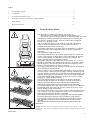
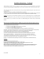
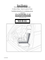
Seat Heaters
Universal: Dual Temperature
Carbon Fiber: Twin Comfort Pads
Installation instructions for seat heating systems
SH-R-01
03 Feb 2009
.
Index
1.
General safety advice . . . . . . . . . . . . . . . . . . . . . . . . . . . . . . . . . . . . . . . . . . . . . . . . . . . . . . . . . . . . . . . 2
2.
Component list
3.
Pre-Installation Summary & OCS.…......................................................................................................................... 4
3.
Installation instructions including OCS / OPDS information . . . . . . . . . . . . . . . . . . . . . . . . . . . . . . . . . . . . . . . . . 5-6
4.
Wiring diagram..….... . . . . . . . . . . . . . . . . . . . . . . . . . . . . . . . . . . . . . . . . . . . . . . . . . . . . . . . . . . . . . . . . . . . . . . . .7
5.
Operating instructions...……. . . . . . . . . . . . . . . . . . . . . . . . . . . . . . . . . . . . . . . . . . . . . . . . . . . . . . . . . . . . . . . . . . .8
A
… . . . . . . . . . . . . . . . . . . . . . . . . . . . . ... . . . . . . . . . . . . . . . . . . . . . . . . . . . . . . . . . . . . . . . . . . . 3
a = min. 250 mm
a = min. 9 1/32”
1.
-
a
a
B
General safety advice
It is impossible to install a Seat Heater kits whenever;
• The seat covers are adhered to the seat’s foam padding, or
• The distance between listing channels are spaced less than 10” apart.
-The battery terminals should be disconnected prior to working on
the vehicle’s electrical circuits. Security codes (radio, navigation
system, etc.) should be noted.
-Do not modify the seat cover or seams of seats with side air-bags.
- Refer to owner’s manual for seats with integrated seat belts or
occupant detection sensors for air bags.
- The heating elements are only allowed to be installed by a qualified
professional who is knowledgeable about electronic systems and
upholstery.
- Use original kit components only.
- The heating elements must be secured and mounted free of folds and
creases. Any exposure to sharp objects will compromise the integrity
of the heating element. For durability and system reliability, the
heating element must be positioned correctly.
- The heating element is only allowed to be operated at +12 V ±3 V. It
should be connected to the onboard power supply via ignition voltage
and the protective fuse should ideally be put in an empty bay in the
fuse box. The maximum fuse rating is 12 amps.
- The heating elements are only allowed to be modified as described in
these installation instructions (B).
- The wire harness must not be modified and must be routed so the seat
can move freely. Contact with sharp edges, bending or pulling of wire
must be avoided to prevent the wire harness from being damaged. The
onboard main supply and wire harness cross-section must be adapted
to the extra current loads if necessary. Refer to the vehicle’s wiring
diagram for additional information.
- The foam padding must be clean and free of any dirt. Sufficient
pressure should be applied to the adhesive sections of the pads to
ensure a solid bond between foam and pad. Do not detach and
reinstall an element after it has been installed for the first time.
- The heating elements must not contact the seat’s electrical conductive
components such as hog rings or the seat’s frame in any way or you
risk the Danger of Short-Circuiting!
- The heating performance at the cover’s surface varies according to the
type of seat or cover. Every millimeter of the cover’s foam thickness
prolongs the heating time by up to 15 seconds.
- The seat heater functions must be explained to the customer and the
Operating Instructions Section of this installation guide must be
provided. The customer must be informed about all safety aspects.
The operating instructions must include the fuse location and its
position.
- The points in the operating instructions must be followed for the
installation.
Warning: Seat heaters must not be installed in vehicles that will be used by paraplegic or other
occupants who cannot sense heat. Customers must notify the original installer if the vehicle is sold to
a third party.
03 Jan 2009
.
2
Pre-Installation Summary – Overview
1. Remove the existing front or rear seat covers.
2. Take note of whether the covers reattach by way of Velcro or Hog rings.
3. The Wire Connector with Purple & Black colored wires is seat the connector which will enable the use of both
High & Low temperature functions.
4. Place the heating pads on the seat and at the Listing Reattachment Area mark the pad with a pen. You will
be cutting 2 holes per pad. The holes should be equidistant. Example: If your listing length for Velcro or hog
rings is 12’ in length then, make a hole at the 4” & 8” point. (The Seat Heaters may also be trimmed in length)
5. Now separate the protective adhesive backing at the backside of the heating pads and carefully align your
pad and holes with the listing area and press the pads against the seat foam to secure the pad in place.
6. Reinstalling the Covers: Tip: For Backrest Covers, turn the cover inside-out and roll the cover back down
the backrest, then reattach the plastic clips. For Seat Bottoms, start by attaching your Velcro or hog ring listings
and then proceed to work outwards. Don’t work from front to back or from left to right – start from the middle
then work outwards!
7. Switch Location: The diameter of the hole for the switch is 13/16” or 21mm & the most common location for
the switch is on the plastic trim located at the side of the seat.
8. Power Sources: The most common sources are the Accessory Panel, Power Seat, Cigarette
Lighter/Accessory Outlet, and Steering Column. However, we recommend drawing power via a relayed keystart trigger sourced directly from the battery. This avoids onboard electronic system interference.
***Warning: Passenger Side Occupancy Detection System for the Air Bags;
You Must Observe the Following:
When you remove the seat bottom seat covers, identify whether or not the seat is equipped with topside
sensors. They are usually visible and resemble flat circular disks which are interconnected or rectangular in
shape. If you are uncertain, you must contact a service department professional for confirmation.
Toyota, Kia and Hyundai usually locate the sensors on top of the seat bottom core foam.
Honda usually locates the sensors on the face of the seat backrest.
In either case, for that particular seat (usually passenger sides only) use only the 2-temp wire connector with
one of our seat heater pads. (Disconnect one of the other pads – you will not need it)
*The dual temperature wire connector is attached to a black and a red wire.
For kits with black and red wires in both elements – Keep the pad which provides 2 colour switch illumination.
This will allow dual temperature function with the use of only a single pad.
Do as the factory does!!
When you purchase a Toyota Sienna from the factory they only heat the passenger side backrest. The Seat
Bottom has NO Heat.
When you purchase a Honda Odyssey from the factory they only heat the passenger seat bottom. The Backrest
has NO Heat.
** Reminder - Whenever a cover is removed and reinstalled Please have the Dealership Service
Department Recalibrate the Seat Sensor to Register “0” –Zero.!!
03 Jan 2009
.
4
2. Component list
A) 2 X Carbon Fiber Heating Pads
B) 1 X Illuminated Hi/Low Switch
C) 1 X Wire Harness – includes a 44” Modular Harness Extension
D) 1 X 5-Pin Automotive Relay
E) 1 X Fuse Holder containing a 10 amp Fuse
F) 4 X Strips of “Heat Transfer Tape”
G) 4 X Quick Zip Ties (To be used as Hog Ring Replacements)
A
F
C
E
B
G
03 Jan 2009
.
D
Installation Instructions
1. Ensure that the vehicle is on a level surface in “Park” & with the hand brake engaged.
2. Disconnect the car’s battery or ensure that the work area is well grounded.
3. Unplug any wires which may be attached / harnessed to the underside of the vehicle’s seat. Proceed to unbolt
the seat from the vehicle’s floor.
4. Carefully remove the seat out of the vehicle to allow for easier access to the vehicle’s seat & seat cover trim
“J” clips.
5. Carefully remove the seat covers off of the seat by detaching the “J” clips which bind the Backrest Cover
together. Then, detach the clips which secure the seat bottom seat cover. These clips secure the cover at the base /
perimeter at the bottom of the seat.
6. Place the backrest pad (10.5” x 19”) & the seat bottom heating pad (10.5” x 19”) against the respective
backrest & seat bottom. Align the heating pads against the seat & “Mark” the listing attachment area to be cut to
allow for the re-installation of the backrest & Cushion covers.
7. Carefully cut no more than 2 holes horizontally or 2 holes vertically from each of the seat heater pads. The
diameter of the each hole should not exceed 1 inch.
Note: The seat heater pads may also be trimmed in length to accommodate a variety of seating styles & listing
locations.
Example – If the seat bottom pad length at 18” is too long then simply trim the heating pad with a pair of scissors
to achieve the desired length.
Do Not: Cut the heating pads widthwise!!! This will render the seat heater useless and void the warranty.
8. Remove the protective backing from the back side of the seat heating pad and carefully adhere the pad to the
seat at the desired location.
9. At this point the holes cut in the pad should align with your identified key listing attachment locations.
Note: Older style listings = wire rod and listing sleeve (requires hog rings for the installation). Newer
style listings incorporate Velcro attachments. For older styles listings secure one of the provided
strips of adhesive tape around the wire listing rod to insulate it.
10. Locate an onboard power source that is able to deliver a continuous 10 Amp current. This source may be
located at your accessory panel, accessory outlet, etc. Consult with the Owner’s Vehicle Manual to ensure an
appropriate location as a source of power source.
11. Once the power source is located extend the wiring harness underneath the carpeting to be able to access this
power source. (Never install the wire directly under where the occupant’s feet would rest)
12. Find a suitable location for your seat heater switches either at the side of the seat, front dash or floor mounted
center console in between the driver and passenger seats.
13. At the desired location drill a 13/16” or 21mm hole and pull the main wiring connector to be attached to the
seat heater switch harness connector through the hole. Attach the switch connector with the main wiring
connector and push everything back through the hole and make sure to push the switch snuggly into the hole until
you hear a “click”.
03 Jan 2009
.
5
Installation Instructions – Continued
14. Re-install the vehicle’s seats and attach the connector which you secured underneath the seat with the
connector pulled up through the carpeting. Make sure to securely re-bolt the vehicle’s seats to the vehicle’s floor.
15. At this point connect the seat heater lead wires to the previously identified safe power source and secure a
good ground base.
16. Make sure to connect your battery terminals and start your ignition.
17. Press the seat heater switch to the upward position for a desired high setting. The middle setting is the Neutral
or “OFF” position. Press the switch down to the lower position to engage the Low temperature setting.
Caution: If at any time you feel that the seat heaters are too hot or causing dizziness due to overheating please
turn off the seat heater and / or take your vehicle to the side of the road and carefully exit the vehicle and wait to
regain composure. If you feel that the seat heaters are malfunctioning please consult with your Professional
Installer.
OCS (Occupant Classification System) / OPDS (Occupant Position Detection System) devices
There are generally three set-ups for sensors.
1. The sensor is located under the seat foam core on the frame.
2. The sensor is located within the seat foam core.
3. The sensor is located on the top surface of either the seat bottom or back foam core.
Historically, Toyota and Honda install sensors on the top surface of the seat bottom and back rest respectively.
Honda continues to deliver the Odyssey EX-L and the Touring equipped with seat heaters.
Honda installs its OPDS (sensor) on the top surface of the passenger backrest.
As a result, it provides Heat for the Bottom only and does not heat the backrest portion of the seat.
Toyota, Hyundai, Kia, BMW etc … equip their seats in the similar way to Honda with a difference
The big difference being that the sensor location is on top of the seat bottom surface not the backrest.
Likewise, they only heat the section which is not equipped with a sensor.
Example - A Toyota Sienna with a passenger side sensor for airbags features a heated backrest only.
Summary:
Follow the example of what the factory does.
Do not place a seat heater pad on top of the OCS / OPDS sensor.
Instead, prepare to install the pad onto the foam core which is not equipped with the sensor.
Simply unplug one of our heating pads from the main harness.
Make sure that the remaining pad is plugged into the connector which provides dual temperature control.
Remove the adhesive backing from the pad and adhere it to the appropriate non-OCS foam section.
Continue with the balance of the installation process as normal.
03 Jan 2009
.
6
Operating instructions for seat heating units - Safety advice
Wiring diagram
03 Jan 2009
7
Operating instructions for seat heating units - Safety advice
**Warning:
The seat heating unit is only allowed to be operated when a person is sitting on it.
This person must be able to feel temperatures and be able to react to them. Persons who experience difficulty
with feeling temperatures – such as all paraplegic persons, children and old people – are not allowed to use the
seat heating unit because there is a risk that they will suffer injury from burns.
The seat heating unit, like any other heating appliance, should not be switched on and left unsupervised. Caution
is to be exercised when near the seat heater switch as to avoid unintentional activation of the seat heating unit.
*If the seat occupant feels an excessive temperature after the seat heating unit has been switched on, change to
a lower temperature setting to reduce heat or switch off completely.
*The heating elements are not allowed to come into contact with sharp metal objects such as knives or tools, or
any object which could penetrate and pierce the seat’s surface and heating elements.
*The “high” setting of the Seat heater is unsuitable for continuous operation.
At the time of installation, the seat heater should not generate heat when vehicle ignition is off.
The recommended location of the seat heater fuse is within 12” of the tapped power source.
Location of Fuse – for customer reference: _____________________________________________________
*The seat heating unit must be switched off after the engine has been switched off. This applies if the installer has
sourced power from a continuous duty plus circuit, and avoids draining the battery.
*Sharp objects are not allowed to be transported or put down on the seat. Excessive weights or heavy objects that
are put down on the seat can cause damage to the seat heating unit and affect its operation adversely. It is
therefore recommended not to put objects on the seat.
*If an unusual smell develops when the seat heating unit is switched on or if there is an uneven distribution of
heat on the seat or backrest – or between the seat and backrest as the case may be – then the seat heating unit
must be switched off immediately and a professional installation center must be contacted. The seat heating unit
is only allowed to be modified or decommissioned by a professional installation center.
*When a seat heater has been switched “on”, the seat is not allowed to be covered with insulating materials
(including blankets or rugs, jackets, cushions, bags, handbags, retro-fitted seat mats, children’s seats, seat
reinforcement, protective covers, etc.). The seat heating unit’s function could be affected if it is operated when
these materials are present: this could risk damage to the seat or burning injuries to seat occupant.
*The seat heating unit is not allowed to be exposed to excessive moisture. Small amounts of the following liquids
do not adversely affect the seat heating unit from being operated safely and continuously after it has dried out:
perspiration, beverages (e.g., coffee, cola, mineral water, etc.), brine (Saltwater - 5 % in solution), cleaning agents
containing ammonia (10 % by volume), cleaning agents containing alcohol (10 % by volume), cleaning agents for
plastic or vinyl, or even soap water.
*Warning: Excessive contact with the any liquids can adversity affect the performance of the seat heating unit and
reduce its service life.
The seat heating element must not be turned on at any time when excessive moisture has dampened the seat
surface or internal components, or both. The seat heating element must not be operated when the occupant is
wearing articles of clothing which is wet or moist. The seat heating element is not to be used for drying clothing or
objects.
03 Jan 2009
8
Operating instructions for seat heating units – Consumer Guide
“HIGH” Temperature Setting:
- The seat heating system is switched ‘ON’ by pressing the switch upwards towards the Double wave
located at the top of the face of the switch.
This will engage the seat heater in the High temperature setting.
This is confirmed by the RED color emitted by the LED light.
LOW Temperature Setting:
- The seat heating system is also switched ‘ON’ by pressing the switch downwards towards the Single
wave located at the bottom of the face of the switch.
This will engage the seat heater in the Low temperature setting.
This is confirmed by the AMBER color emitted by the LED light.
Note:
-The seat heating element is switched “ON” by moving the switch upwards or downwards from its
center OFF position..
-The heating time can vary according to the type of seat cover material and kind of clothing or coat that
is being worn. The heating must be switched to the ‘Low’ setting in order to avoid overheating, when
the desired temperature has been achieved.
Caution:
The heat will be noticeable within 4 - 5 minutes. The heating must be switched off in order to avoid
overheating, whenever the temperature is too high.
Troubleshooting:
The Heating does not function although it is
switched on.
The LED is not illuminated.
C Verify the fuse and change it if necessary.
Co Consult a Professional Installer if the fuse is in
order.
The LED is not illuminated although the
heating is functioning and switched ON.
The Heating does not function although it is
switched on.
The LED is ON.
The LED in the switch is defective
The distribution of heat in the seat or back
is uneven.
Switch off the seat heating unit and Consult a
Professional Installation Center.
The fuse burns out repeatedly.
Check the fuse rating. Consult a Professional
Installation Center if the fuse rating is correct.
The temperature of the seat cover may be too high due
to the high interior temperature of the vehicle. The
thermostat in the seat heater is connected. Wait until
the seat cover’s temperature has fallen and try again.
03 Jan 2009
9