1
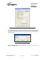
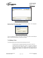
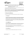
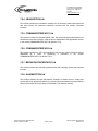
NEPTUNE Subsea System
User Manual
Document Number:
Revision:
Project Name:
Project Number:
Author:
Date:
0848-RPT002
1.0
NEPTUNE
0848
Graham Cunliffe
27-FEB-09
OceanWorks International
120 – 6741 Cariboo Road
Burnaby, BC V3N 4A3
Canada
www.oceanworks.com
OceanWorks International
120 – 6741 Cariboo Road
Burnaby, BC V3N 4A3
Canada
www.oceanworks.com
Document History
Revision
0.2
1.0
Description
Document Draft
Final Release
Date
01-MAY-08
27-FEB-09
Document Number: 0848-RPT002
Author: Graham Cunliffe
Author
Guy Druce
Graham Cunliffe
Subsea System User Manual
Page 2 of 27
Revision 1.0
OceanWorks International
120 – 6741 Cariboo Road
Burnaby, BC V3N 4A3
Canada
www.oceanworks.com
Table of Contents
Table of Contents................................................................................................. 3
List of Figures....................................................................................................... 5
List of Tables........................................................................................................ 5
List of Abbreviations............................................................................................. 6
1. Introduction ................................................................................................... 7
1.1. Purpose of Document ............................................................................ 7
1.2. Reference Documents ........................................................................... 7
1.3. General Information ............................................................................... 7
2. Principles of Operation.................................................................................. 8
2.1. General Operation ................................................................................. 8
2.2. Transportation........................................................................................ 8
2.3. Installation.............................................................................................. 8
2.4. Safety Considerations............................................................................ 8
3. Deployment Procedure ................................................................................. 9
3.1. Mechanical and Electrical Interfaces...................................................... 9
3.2. Pre-deployment Testing......................................................................... 9
3.3. Command Interface ............................................................................. 10
3.4. Data Handling Interface ....................................................................... 10
4. Recovery Procedure ................................................................................... 10
5. Junction Box Operational Modes and Procedures ...................................... 10
5.1. Power ON/OFF and Initiation of Software ............................................ 10
5.2. Operational Calibration Procedures ..................................................... 11
5.3. Methods of Commanding and Collecting Data from the System.......... 11
6. Software Operational Procedure ................................................................. 11
6.1. Software Start-up ................................................................................. 11
6.2. Normal Operations............................................................................... 11
6.2.1. System Status Conditions............................................................. 11
6.2.2. Breaker Status Conditions ............................................................ 12
6.3. Fault Conditions ................................................................................... 12
6.3.1. System Fault Conditions............................................................... 12
6.3.2. Breaker Fault Condition ................................................................ 12
7. Maintenance Procedures ............................................................................ 13
7.1. Periodic Maintenance Requirements ................................................... 13
7.2. Test Equipment and Special Tools Required ....................................... 13
7.3. Flashing Junction Box Firmware .......................................................... 14
7.4. Software Tools ..................................................................................... 17
7.5. Flashing Junction Box Firmware .............Error! Bookmark not defined.
7.6. Subsea Code Modules......................................................................... 18
7.6.1. Node.C.......................................................................................... 18
7.6.2. JBDEFS.Lib .................................................................................. 18
Document Number: 0848-RPT002
Author: Graham Cunliffe
Subsea System User Manual
Page 3 of 27
Revision 1.0
OceanWorks International
120 – 6741 Cariboo Road
Burnaby, BC V3N 4A3
Canada
www.oceanworks.com
7.6.3. JBTCP.Lib..................................................................................... 18
7.6.4. JBAQUISITION.Lib ....................................................................... 19
7.6.5. COMMANDINTERFACE1.Lib....................................................... 19
7.6.6. COMMANDINTERFACE.Lib......................................................... 19
7.6.7. BROADCASTINTERFACE1.Lib ................................................... 19
7.6.8. ALARMACTION.Lib ...................................................................... 19
7.6.9. LIB.Dir........................................................................................... 20
APPENDIX A – The UDP Data Structure ........................................................... 21
7.1. Introduction .......................................................................................... 21
7.2. Number Representation....................................................................... 21
7.3. UPD Data Frame Format ..................................................................... 21
7.4. Frame Header...................................................................................... 23
7.5. Breaker Array....................................................................................... 24
7.6. Hotel Array........................................................................................... 25
7.7. Message Data...................................................................................... 26
7.8. UDP Data Stream Object ..................................................................... 26
Document Number: 0848-RPT002
Author: Graham Cunliffe
Subsea System User Manual
Page 4 of 27
Revision 1.0
OceanWorks International
120 – 6741 Cariboo Road
Burnaby, BC V3N 4A3
Canada
www.oceanworks.com
List of Figures
Figure 7.3.1. RFU Main Screen.......................................................................... 14
Figure 7.3.2. RFU “Communications Options” Screen ....................................... 15
Figure 7.3.3. RFU “Discovery” Screen ............................................................... 15
Figure 7.3.4. RFU “Communications Options” Screen with Programmer
Information ......................................................................................................... 16
Figure 7.3.5. RFU “Choose Flash Image” Screen .............................................. 16
Figure 7.3.6. RFU “Browse for Image” Screen ................................................... 17
Figure 7.3.7. RFU “Passphrase” Screen ............................................................ 17
List of Tables
Table 1.2.1. List of Reference Documents ........................................................... 7
Table 6.2.1.1. Subsea Software System Status Bits .......................................... 12
Table 6.2.2.1. Subsea Software Breaker Status Bits.......................................... 12
Table 6.3.1.1. Subsea Software System Fault Conditions ................................. 12
Table 6.3.2.1. Subsea Software Breaker Shut Down Conditions ....................... 13
Document Number: 0848-RPT002
Author: Graham Cunliffe
Subsea System User Manual
Page 5 of 27
Revision 1.0
OceanWorks International
120 – 6741 Cariboo Road
Burnaby, BC V3N 4A3
Canada
www.oceanworks.com
List of Abbreviations
The following abbreviations are used throughout this document.
AC
ADC
DC
HV
JB
LV
MVC
NEPTUNE
RFU
ROV
UDP
Alternating Current
Analogue to Digital Converter
Direct Current
High Voltage
Junction Box
Low Voltage
Medium Voltage Converter
North-East Pacific Time-series Undersea Networked Experiments
Rabbit Field Utility
Remotely Operated Underwater Vehicle
User Datagram Protocol
Document Number: 0848-RPT002
Author: Graham Cunliffe
Subsea System User Manual
Page 6 of 27
Revision 1.0
OceanWorks International
120 – 6741 Cariboo Road
Burnaby, BC V3N 4A3
Canada
www.oceanworks.com
1. Introduction
1.1. Purpose of Document
The purpose of the document is to provide the user with a reference to the nature of the
North-East Pacific Time-series Undersea Networked Experiments (NEPTUNE) Junction Box
(JB) subsea hardware and software; the deployment and operational use thereof.
1.2. Reference Documents
The documents in Table 1.2.1 are relevant to the operation of the JB and should be read in
unison with this report.
Table 1.2.1. List of Reference Documents
Document Title
Document Revision
Document Number
Assembly Drawings
NEPTUNE Lifting Frame Assembly Drawing
NEPTUNE Assembly Alignment Fixture
3
2
0848-250-T30000
0848-250-T20000
2.0
0848-RPT001
1.4
N/A
N/A
N/A
Other Documents
0848-RPT001 NEPTUNE Junction Box System
Design Document
Junction Box Telnet Command Manual
NEPTUNE Calibration File Format
1.3. General Information
The NEPTUNE JB is cylindrical, 13.2” (33.5 cm) in diameter by 40” (101.6 cm) in length. It
should be noted that this length does not include the SeaCon connectors which extend
approximately 1” (2.5 cm) beyond the end plate of the JB.
The JB weighs approximately 400 lbs (181kg) in air and approximately 202 lbs (91.5kg) in
fresh water.
The JB is equipped with the two following custom tooling items:
-
NEPTUNE Lifting Frame Assembly, part number 0848-250-T30000
NEPTUNE Assembly Alignment Fixture, part number 0848-250-T20000
The NEPTUNE Lifting Frame Assembly is designed to be used for both lifting and securing
the JB during transportation. The NEPTUNE Assembly Alignment Fixture is designed to be
used when inserting the JB chassis into the pressure vessel.
The JB is shipped in a custom fabricated crate. The crate empty weight is approximately 60
lbs (27.2 kg) and must be accounted for when handling the crated JB.
Document Number: 0848-RPT002
Author: Graham Cunliffe
Subsea System User Manual
Page 7 of 27
Revision 1.0
OceanWorks International
120 – 6741 Cariboo Road
Burnaby, BC V3N 4A3
Canada
www.oceanworks.com
2. Principles of Operation
2.1. General Operation
The JB receives 400VDC from a Medium Voltage Converter (MVC) and distributes low
voltage (LV) to six to ten instrument ports at 12VDC, 15VDC, 24VDC, 48VDC and high
voltage (HV) to up to three ports at 400VDC as defined in the NEPTUNE Junction Box
System Design Document (0848-RPT001). The JB has a single 1000Baset fiber or 100BaseT
copper uplink and up to ten Ethernet links and four EIA232, EIA422 or EIA485 (2-wire or 4wire) serial links.
The JB is controlled by the subsea software which can be accessed remotely via TELNET.
The user is able to control the state of the instrument ports and is provided feedback in the
form of telemetry from the JB.
2.2. Transportation
During transportation the JB must be kept within the temperature range of -20°C to +70°C.
The JB should be transported in crates that provide sufficient protection to the JB and, if fit,
the extruding ODI penetrator. O-rings for the JB face SeaCon connectors should not be fit,
but rather bagged, tagged and attached to the ODI penetrator. The SeaCon connectors and
ODI Remotely Operated Underwater Vehicle (ROV) connector should have dust caps
installed to prevent contaminants from entering them.
2.3. Installation
When connecting the uplink and instruments to the JB, ensure that O-rings are installed in
the SeaCon faces and that all connectors (SeaCon and ODI) are properly seated. Do not hot
swap either the SeaCons or the ODI.
2.4. Safety Considerations
During transportation and installation, the NEPTUNE Lifting Frame Assembly should be used
to move the JB whenever possible. All lifting devices, slings, support fixtures, cradles and
other equipment used to move or secure the JB must be rated for safe working loads that
exceed that of the JB (crated and uncrated).
Document Number: 0848-RPT002
Author: Graham Cunliffe
Subsea System User Manual
Page 8 of 27
Revision 1.0
OceanWorks International
120 – 6741 Cariboo Road
Burnaby, BC V3N 4A3
Canada
www.oceanworks.com
3. Deployment Procedure
3.1. Mechanical and Electrical Interfaces
The junction box end plate has 10 SeaCon connectors, numbered J1 through J10. The steps
below outline the installation of cables on the JB SeaCon connectors:
-
-
Check that the JB output ports are disabled.
Check that the connectors are clean and free of dust or debris.
Install o-ring in the face of the SeaCon connector. Ensure that the o-ring is
properly lubed, that there is no dust or debris on it and that it is seated properly in
the connector.
Align the key slots of the cable connector with that of the JB SeaCon.
Keeping the key slots aligned, push the cable connector onto the JB SeaCon. If
the key slots are not properly aligned, slowly rotate the cable connector until it
slides onto the JB SeaCon.
Turn the threaded portion of the cable connector until it is hand tight.
The steps below outline the installation of cables to the ODI Remote Operated underwater
Vehicle (ROV) connector:
-
Check that the power supply to the JB is not live.
Check that the connector faces are clean and free of dust or debris.
Align the key slots of the connectors.
Push the cable into the ODI ROV receptacle.
Ensure that no yellow is visible on the side of the ODI ROV connector. If yellow is
visible a proper mate was not made. In this case remove the connectors and
restart the process.
Precautions must be taken so that the weight of the cables is not born by the connectors and
suitable strain relief techniques must be employed to prevent damage to the connectors.
Care must also be taken to prevent kinking of the cables.
3.2. Pre-deployment Testing
Prior to deploying the JB confirm the following:
-
JB powers up.
All internal JB network devices can be pinged via the primary and secondary
uplinks.
JB ports can be controlled via Telnet and expected voltage outputs are seen at
the ports.
Communication links can be established on serial ports (if applicable).
Communication links can be established on 100BaseT ethernet ports.
During this testing, the JB must be secured in a manner that prevents it from rolling on the
surface that it is placed upon. The NEPTUNE Lifting Frame Assembly is an option for this.
Document Number: 0848-RPT002
Author: Graham Cunliffe
Subsea System User Manual
Page 9 of 27
Revision 1.0
OceanWorks International
120 – 6741 Cariboo Road
Burnaby, BC V3N 4A3
Canada
www.oceanworks.com
Do not apply power to the JB unless it is electrically bonded to the power supply chassis. This
ensures that there is no potential between the JB chassis and earth ground. This bonding
protects personnel who are either floating with respect to earth or bonded to earth via ESD
measures. This bonding can be achieved by connecting the JB to earth ground with a
#8AWG or larger wire. Using a large gauge wire simulates the deployed environment of the
JB where the resistance seen between the earth reference point of all devices approaches
0Ω. The holes in the pressure vessel can heads used to fasten the can head mounting jig are
an ideal bonding point for the JB. OceanWorks strongly recommends that earth bonding of
the JB is standard procedure whenever the JB is powered outside of seawater.
3.3. Command Interface
The command interface to the subsea software is achieved via TELNET. For more
information refer to the Junction Box Telnet Command Manual.
3.4. Data Handling Interface
Telemetry data is transmitted from the subsea system as a UDP data stream. Refer to
Appendix A where the UDP data structure is defined.
4. Recovery Procedure
When recovering the JB, first ensure that the JB is not powered. Once this has been
established the ODI ROV cable can be disconnected. Before disconnecting instrument
cables, dry the JB can head so that there is no liquid present on or around the SeaCon
connectors. Compressed air or a heater can be used to make sure that all liquid is removed.
If the JB is to be opened, follow the same procedure as with the SeaCon cables to make sure
that no liquid enters the pressure vessel. The NEPTUNE Assembly Alignment Fixture, part
number 0848-250-T20000, should be used when opening the JB to make sure that
components of the pressure vessel are not damaged.
5. Junction Box Operational Modes and Procedures
5.1. Power ON/OFF and Initiation of Software
When the JB is powered up all of the breakers enter a safe state (output disabled) and the
control computer automatically boots the subsea software. A 60 second lockout is imposed
on the breakers so that they cannot be switched on before their input Negative Time
Constant (NTC) thermistors have returned to their high impedance value. This protects the
breakers in the case of a rail crash, i.e. if the JB looses power from the MVC with breakers
on, the breakers cannot be switched back on before it is safe to do so without causing
damage.
Once the subsea software has booted, telemetry data is sent via the UDP data stream.
Document Number: 0848-RPT002
Author: Graham Cunliffe
Subsea System User Manual
Page 10 of 27
Revision 1.0
OceanWorks International
120 – 6741 Cariboo Road
Burnaby, BC V3N 4A3
Canada
www.oceanworks.com
After the initial 60 second lockout period has passed, control of the JB breakers via TELNET
is possible.
5.2. Operational Calibration Procedures
Refer to the NEPTUNE Calibration File Format document for a detailed description of how to
create a JB calibration file.
5.3. Methods of Commanding and Collecting Data from the
System
The subsea software is controlled via TELNET. Refer to the Junction Box Telnet Command
Manual for more information.
Refer to Appendix A for information regarding JB telemetry data.
6. Software Operational Procedure
6.1. Software Start-up
The JB control computer starts running the subsea software automatically when the JB is
powered up. Telemetry data is sent to the surface as soon as the subsea software has
started.
On start-up, the JB control computer performs the initialization operations that are
summarized below:
-
The control computer board and Analogue to Digital Converters (ADC) are
initialized. This phase takes approximately 30ms.
The Ethernet interface and communications are initialized. This phase takes
approximately 3630ms.
The Ethernet controller type is determined and appropriate set-up actions are
performed based on the controller type. This phase takes approximately 140ms.
Internal data structures for telemetry are set up and the breakers are
commanded to enter the OFF state via software. This occurs approximately
3800ms after power on.
The JB controller software enters its main loop in which Telnet commands are
responded to, telemetry data is acquired, fault conditions are detected and
telemetry is transmitted via UDP. The main loop is typically started 3900ms after
power on.
6.2. Normal Operations
6.2.1. System Status Conditions
The subsea software defines the system status bits given in Table 6.2.1.1.
Document Number: 0848-RPT002
Author: Graham Cunliffe
Subsea System User Manual
Page 11 of 27
Revision 1.0
OceanWorks International
120 – 6741 Cariboo Road
Burnaby, BC V3N 4A3
Canada
www.oceanworks.com
Table 6.2.1.1. Subsea Software System Status Bits
System Status Condition
Command Link Status
Auto-calibration Bit
ADC Setting Bit
System Status
Bit
1
5
7
Bit = 0
Bit = 1
OFF
OFF
± 10VDC
ON
ON
0-5VDC
6.2.2. Breaker Status Conditions
The subsea software defines the breaker status bits given in Table 6.2.2.1.
Table 6.2.2.1. Subsea Software Breaker Status Bits
Breaker Status Condition
FET ON Bit
Rely ON Bit
Over-current INHIBIT Bit
Breaker Status
Bit
0
1
8
Breaker Hold-off Bit
9
Bit = 0
Bit = 1
OFF
OFF
NOT
INHIBITED
NO HOLDOFF
ON
ON
INHIBITED
WAITING
FOR
HOLD- OFF
TIME
6.3. Fault Conditions
6.3.1. System Fault Conditions
The subsea software generates a system fault for the conditions given in Table 6.3.1.1.
Table 6.3.1.1. Subsea Software System Fault Conditions
System Status
Bit
2
6
Fault Condition
TCP send error
Auto-calibration error
6.3.2. Breaker Fault Condition
The subsea software monitors critical breaker parameters and compares them to user
specified limits at frequency of 1Hz. If a fault is detected, the breaker experiencing it will
be shut down. The error conditions are given in Table 6.3.2.1.
Document Number: 0848-RPT002
Author: Graham Cunliffe
Subsea System User Manual
Page 12 of 27
Revision 1.0
OceanWorks International
120 – 6741 Cariboo Road
Burnaby, BC V3N 4A3
Canada
www.oceanworks.com
Table 6.3.2.1. Subsea Software Breaker Shut Down Conditions
Breaker Fault Condition
Breaker Status
Bit
3
4
5
6
Over-current Fault
Ground-fault
Low Voltage Fault
High Voltage Fault
Bit = 0
Bit = 1
NO FAULT
NO FAULT
NO FAULT
NO FAULT
FAULT
FAULT
FAULT
FAULT
7. Maintenance Procedures
7.1. Periodic Maintenance Requirements
The following mechanical items should be checked when the JB has been recovered from a
subsea deployment:
-
Check pressure vessel for signs corrosion.
Check cable pins for signs of corrosion.
Replace SeaCon connector o-rings.
Replace pressure vessel can head o-rings if JB is opened.
Check the alignment of paint marks on pressure vessel fasteners, pressure
release valve and purge plug.
Updated firmware should be flashed to the JB upon availability. This firmware includes:
-
Subsea software
MOXA EDS510A firmware
MOXA EDS508A firmware
MOXA NPort 5450I firmware
7.2. Test Equipment and Special Tools Required
It is recommended that the test equipment and special tools given listed below be utilized
when bench testing the JB to allow for complete testing and operation of the device.
-
400VDC Power Supply
LV DC Load Bank
HV (400VDC) DC Load Bank
HV Insulation Strength Tester
Digital Multimeter
Current Clamp Meter
Oscilloscope
Laptop
Managed Ethernet Switch
Junction Box Serial Isolation Card Assembly
Ethernet Serial Server
6 x CAT5e Patch Cables
2 x EIA232 Crossover Cable
2 x EIA485 Crossover Cable
Document Number: 0848-RPT002
Author: Graham Cunliffe
Subsea System User Manual
Page 13 of 27
Revision 1.0
OceanWorks International
120 – 6741 Cariboo Road
Burnaby, BC V3N 4A3
Canada
www.oceanworks.com
-
NEPTUNE Lifting Frame Assembly
NEPTUNE Assembly Alignment Fixture
7.3. Flashing Junction Box Firmware
The following section details the steps required to download the NEPTUNE subsea controller
firmware.
Tools required:
-
Rabbit Field Utility (RFU) version 2.5 (Z-World)
When the RFU is run, the main screen as seen in Figure 7.3.1 is presented.
Figure 7.3.1. RFU Main Screen
Communications with the JB must be set up. This is accomplished by selecting “Setup” on the
menu bar of the main screen. The “Communications Options” screen given in Figure 7.3.2 will be
displayed.
Document Number: 0848-RPT002
Author: Graham Cunliffe
Subsea System User Manual
Page 14 of 27
Revision 1.0
OceanWorks International
120 – 6741 Cariboo Road
Burnaby, BC V3N 4A3
Canada
www.oceanworks.com
Figure 7.3.2. RFU “Communications Options” Screen
Ensure that the TCP/IP option “Use TCP/IP Connection” radio button is selected. If the
Network Address displayed is correct, click the “OK” button to proceed. Otherwise, the RFU
needs to find programmer units that it can communicate with. This is accomplished by
clicking the “Discover” button. The “Discovery” screen given in Figure 7.3.3 is then displayed.
Figure 7.3.3. RFU “Discovery” Screen
Once the RFU has located programmers that it can communicate with, a list of such
programmers is presented in the “Discovery” screen. Select the desired programmer by
clicking the line that it is presented on and then click the “Select” button. The result of these
actions should be to place the desired programmer’s IP address in the “Communications
Options” screen as shown in Figure 7.3.4.
Document Number: 0848-RPT002
Author: Graham Cunliffe
Subsea System User Manual
Page 15 of 27
Revision 1.0
OceanWorks International
120 – 6741 Cariboo Road
Burnaby, BC V3N 4A3
Canada
www.oceanworks.com
Figure 7.3.4. RFU “Communications Options” Screen with Programmer Information
If the programmer’s IP address displayed in the “Network Address” field is correct, click the
“OK” button. Now select “File” on the menu bar in the main screen. This will bring up the
“Choose Flash Image” screen (see Figure 7.3.5), where you select the binary image to
download to the JB.
Figure 7.3.5. RFU “Choose Flash Image” Screen
Browse for the desired file by clicking the browse button. A screen similar to that shown in
Figure 7.3.6 will be displayed.
Document Number: 0848-RPT002
Author: Graham Cunliffe
Subsea System User Manual
Page 16 of 27
Revision 1.0
OceanWorks International
120 – 6741 Cariboo Road
Burnaby, BC V3N 4A3
Canada
www.oceanworks.com
Figure 7.3.6. RFU “Browse for Image” Screen
Once the correct image has been located, click the file name to select it. The “Passphrase”
screen (see Figure 7.3.7) is then presented.
Figure 7.3.7. RFU “Passphrase” Screen
There is no passphrase imposed on the system, so click the “OK” button to start loading the
image. This will take approximately 70 seconds to accomplish.
7.4. Software Tools
The following software tools are required for the maintenance of the JB:
-
Z-World© Dynamic C integrated development environment, version 9.21.
-
Z-World© Remote Field Utility (RFU,) version 2.5 (required for loading the
binary image onto the sub-sea controller). It is possible (and useful) to
compile and load directly to the sub-sea board from the IDE and for
development and testing of the software this is the preferred mode of
operation.
Document Number: 0848-RPT002
Author: Graham Cunliffe
Subsea System User Manual
Page 17 of 27
Revision 1.0
OceanWorks International
120 – 6741 Cariboo Road
Burnaby, BC V3N 4A3
Canada
www.oceanworks.com
It is strongly recommended that for the final “production” load of the software the code be
compiled to the target board (compiler Project Options) and then loaded via the RFU. The
target board is:
- 44MHz BL2600, 512K Flash, 256K+512K SRAM
Rabbit 3000 Revision: IL1T/IZ1T
The above procedure ensures that the binary (.bin) image is the one that is being run on the
board and thus can be loaded to other JBs as required.
While not a prerequisite for the maintenance of the subsea code, OceanWorks strongly
recommends the use of a network protocol analyzer such as WIRESHARK. This type of
software is very useful in isolating problems pertaining to IP addressing and validating the
contents of the User Datagram Protocol (UDP) telemetry stream.
7.5. Subsea Code Modules
The sub-sea code consists of the following modules (libraries in Dynamic C terminology):
7.5.1. Node.C
This is the main program module for the subsea code. Program start and initialisation are
performed here as well as the main program loop in which commands are received and
responded to; telemetry is acquired and transmitted and fault conditions are detected.
The error handler is also in this module. The error handler is invoked if the watchdog
timer expires. The error handler forces a restart of the sub-sea software (equivalent to
power cycling the controller board).
7.5.2. JBDEFS.Lib
This module contains all defines and global data structures required by the sub-sea
software. Global values are identified by the prefix “G_” for example: G_newIpAddr.
Defined constants are capitalized, for example: FAULT_CHECK_INTERVAL.
There are some definitions pertaining to the TCP communications that are derived from
the module JBTCP.LIB (Section 7.5.3).
7.5.3. JBTCP.Lib
This module contains some additional definitions specific to the TCP routines.
Document Number: 0848-RPT002
Author: Graham Cunliffe
Subsea System User Manual
Page 18 of 27
Revision 1.0
OceanWorks International
120 – 6741 Cariboo Road
Burnaby, BC V3N 4A3
Canada
www.oceanworks.com
7.5.4. JBAQUISITION.Lib
This module contains the initialisation modules for the telemetry related data structures
and help function; the telemetry acquisition functions and the breaker command
functions.
7.5.5. COMMANDINTERFACE1.Lib
This module contains the command parser code. The command and possible devices are
identified here and the execution of the function is dispatched to the appropriate function
in the module COMMANDINTERFACE.Lib (Section 7.5.6).
7.5.6. COMMANDINTERFACE.Lib
This module contains the TCP communications code and the various functions that are
dispatched as a result of processing a command in the module
COMMANDINTERFACE1.Lib (Section 7.5.5).
7.5.7. BROADCASTINTERFACE1.Lib
This module contains the code that synthesizes the UDP telemetry stream and transmits
the data.
7.5.8. ALARMACTION.Lib
This module contains the code that detects violations of breaker current, voltage and
ground-fault limits. Appropriate actions (e.g. shutting down the breaker) are taken and the
relevant error status is set (the latter is transmitted in the telemetry stream).
Document Number: 0848-RPT002
Author: Graham Cunliffe
Subsea System User Manual
Page 19 of 27
Revision 1.0
OceanWorks International
120 – 6741 Cariboo Road
Burnaby, BC V3N 4A3
Canada
www.oceanworks.com
LIB.Dir
This file contains a list of all the modules (custom and Z-World) required to compile the
sub-se controller code. The following lines (located at the start of the file) MUST be
maintained as the modules, or their folder is renamed:
C:\Projects\0848-100-SWA10520 v2.3.1\JBDEFS.LIB
C:\Projects\0848-100-SWA10520 v2.3.1\JBTCP.LIB
C:\Projects\0848-100-SWA10520 v2.3.1\COMMANDINTERFACE.LIB
C:\Projects\0848-100-SWA10520 v2.3.1\COMMANDINTERFACE1.LIB
C:\Projects\0848-100-SWA10520 v2.3.1\BROADCASTINTERFACE.LIB
C:\Projects\0848-100-SWA10520 v2.3.1\JBAQUISITION.LIB
C:\Projects\0848-100-SWA10520 v2.3.1\ALARMACTION.LIB
C:\Projects\0848-100-SWA10520 v2.3.1\BL26XX.LIB
The above file is used by the compiler to specify which libraries are required to compile
the sub-sea code. The appropriate library file MUST be specified in the compiler Project.
The file BL26XX.LIB is a Z-World library file that is specific to the BL2600 Wolf board.
Specifically, the function AnaIn defined in this library has been modified in order to
remedy a bug in the supplied library. The sub-sea software MUST be complied using this
modified library file.
Document Number: 0848-RPT002
Author: Graham Cunliffe
Subsea System User Manual
Page 20 of 27
Revision 1.0
OceanWorks International
120 – 6741 Cariboo Road
Burnaby, BC V3N 4A3
Canada
www.oceanworks.com
APPENDIX A – The UDP Data Structure
A.1. Introduction
The NEPTUNE system UDP data frame format is described in the following section. The
UDP frame type 102 is described, as of subsea software release v2.4.6 and later.
A.2. Number Representation
Numbers, as represented in the Rabbit microprocessor, are little-endian, hence the most
significant byte in the two byte numeric values is at the higher address of the two bytes in the
data stream.
UDP telemetry values are in ADC ticks and are integer values between 0 and 2047.
A.3. UPD Data Frame Format
The format of the raw format UDP data is as follows:
Document Number: 0848-RPT002
Author: Graham Cunliffe
Subsea System User Manual
Page 21 of 27
Revision 1.0
OceanWorks International
120 – 6741 Cariboo Road
Burnaby, BC V3N 4A3
Canada
www.oceanworks.com
Frame Header
16 Bytes
Packet Type
1
Device Id
9
Frame Counter
2
System Status
2
Digital Input State
2
Breaker Array
Breaker 1
22 * 10 = 220 Bytes
Status
2
Peak Current Value
2
Current Value
2
Current Limit
2
Current Timeout
2
Voltage Value
2
Voltage Low Limit
2
Voltage High Limit
2
Ground Fault Value
2
Ground Fault Low Limit
2
Ground Fault High Limit
2
•••
Hotel Array
Input 1
7 * 12 = 84 Bytes
Status
1
Value
2
Low Limit
2
High Limit
2
•••
Message Array
Message 1
63 * 1= 63 Bytes
Status
1
Message
63
•••
Document Number: 0848-RPT002
Author: Graham Cunliffe
Subsea System User Manual
Page 22 of 27
Revision 1.0
OceanWorks International
120 – 6741 Cariboo Road
Burnaby, BC V3N 4A3
Canada
www.oceanworks.com
The UDP data structure and element sizes are presented in detail in Section A.8. Sections
A.4 through A.7 provide details on the frame header, Beaker array, Hotel array and message
data respectively.
A.4. Frame Header
The frame header consists of five fields, described below:
Packet Type
Device Id
Unsigned byte
Character array
1 bytes
9 bytes
Frame Counter
Unsigned integer
2 bytes
System Status
Unsigned integer
2 bytes
Digital Input State
Unsigned integer
2 bytes
The system status has the following format:
7
6
5
4
3
2
1
0
ADC
mode
ACL
Err
ACL
On
Master
On
TCM2
Status
TCP
Snd Err
CL
Status
unused
15
14
13
12
11
10
9
8
unused
unused
unused
unused
unused
unused
WD trip
bit
EH set
bit
The following abbreviations are used in the above bit field description:
CL status
TCP Snd Err
TCM2 Status
Master On Bit
ACL On Bit
ACL Err Bit
ADC mode
EH set bit
WD trip bit
- 1 indicates TCP link established; 0 No link.
- 1 indicates that a TCP send error occurred.
- 1 indicates that the TCM2 compass is present 1.
- 1 indicates that the Node is master; 0 not master2.
- 1 indicates that auto-calibration is on; 0 off.
- 1 indicates an error in the 2.5v reference voltage3.
4
- 1 indicates that the ADC is in 0-5v range mode .
- 1 indicates that the last reboot was done by the error handler5.
- 1 indicates that the last reboot was due to the watchdog timing out6.
1
The TCM2 compass is present only in a VENUS NODE A sub-sea system.
Master status only applies to VENUS NODE A sub-sea systems.
3
This bit is set if the difference between the ADC ticks for the 2.5 volt reference and the computed value
for the ADC setting is greater than 61. For the ±10 volt ADC the 2.5 volt reference is nominally 1280 ticks
and for 0-5 volt ADC the reference is 1024.
4
VENUS uses a ±10 volt ADC range; NEPTUNE uses 0-5 volt.
5
Sub sea firmware release r2.4.5 and up.
6
Sub sea firmware release r2.4.5 and up.
2
Document Number: 0848-RPT002
Author: Graham Cunliffe
Subsea System User Manual
Page 23 of 27
Revision 1.0
OceanWorks International
120 – 6741 Cariboo Road
Burnaby, BC V3N 4A3
Canada
www.oceanworks.com
The digital input state has the following format:
7
6
5
4
3
2
1
0
0
0
0
0
0
0
0
0
15
14
13
12
11
10
9
8
HB
Led
Fault
Led
1
1
RLT
CP
FET
CP
RLY
Ch.
FET
Ch.
The following abbreviations are used in the above bit field description:
FET Ch.
RLY Ch.
FET CP
RLY CP
Fault Led
HB Led
- 1 indicates that the FET control signal line is high7.
- 1 indicates that the relay control signal line is high.
- 1 indicates that the FET clock signal line is high.
- 1 indicates that the relay clock signal line is high.
- 1 indicates that the SIIM interface board fault LED is ON8.
- 1 indicates that the SIIM interface board “heartbeat” LED is ON9.
A.5. Breaker Array
The breaker array consists of ten repeating groups of fields, each breaker being represented
by the following data:
Status
Unsigned integer
2 bytes
Peak Current Value
Signed integer
2 bytes
Current Value
Signed integer
2 bytes
Current Limit
Signed integer
2 bytes
Current Timeout
Signed integer
2 bytes
Voltage Value
Signed integer
2 bytes
Voltage Low Limit
Signed integer
2 bytes
Voltage High Limit
Signed integer
2 bytes
Ground Fault Value
Signed integer
2 bytes
Ground Fault Low Limit
Signed integer
2 bytes
Ground Fault High Limit
Signed integer
2 bytes
The breaker status has the following format:
7
The FET and RLY channel and clock signal lines are high by default.
The fault LED is turned on whenever a breaker is tripped by the sub-sea controller software due to a
breaker limit being exceeded.
9
During normal operation this bit is toggled at 1 Hz.
8
Document Number: 0848-RPT002
Author: Graham Cunliffe
Subsea System User Manual
Page 24 of 27
Revision 1.0
OceanWorks International
120 – 6741 Cariboo Road
Burnaby, BC V3N 4A3
Canada
www.oceanworks.com
7
6
5
4
3
2
1
0
VR
Fault
UV
Fault
OV
Fault
Ground
Fault
OC
Fault
OC
Warn
RLY
ON
FET
ON
15
14
13
12
11
10
9
8
unused
unused
unused
unused
unused
unused
Alarm
Inhibit
Hold
Off
The following abbreviations are used in the above bit field description:
RLY
OC
OV
UV
VR
Hold Off
Alarm Inhibit11
- Relay
- Over Current
- Over Voltage
- Under Voltage
- Voltage Ripple10
- Set if breaker hold-off time is greater than zero.
- Set when breaker is turned on for one UDP frame.
A.6. Hotel Array
The hotel array consists of twelve repeating groups of fields, each analogue input being
represented by the following data:
Status
Unsigned integer
1 byte
Value
Signed integer
2 bytes
Low Limit
Signed integer
2 bytes
High Limit
Signed integer
2 bytes
The analogue data status has the following format:
7
6
5
4
3
2
1
0
unused
unused
unused
unused
unused
unused
High
Fault
Low
Fault
The Low Fault and High Fault indications correspond to the value exceeding the specified
limits for the input12.
10
This fault condition is set by the VENUS system shore station software only
Note that that this bit should never be one for more than one UDP frame at a time. The bit is set to
prevent alarm checking for one second after a breaker is turned on so as to allow for the telemetry to
stabilise.
12
This mechanism is included in case there is a need in the future to deal with analogue inputs other than
the breakers requiring fault checking. At this time the status field is not used.
11
Document Number: 0848-RPT002
Author: Graham Cunliffe
Subsea System User Manual
Page 25 of 27
Revision 1.0
OceanWorks International
120 – 6741 Cariboo Road
Burnaby, BC V3N 4A3
Canada
www.oceanworks.com
A.7. Message Data
The message data consists of a single message field, represented by the following data:
Status
Unsigned integer
1 byte
Message Text
Character array
63 bytes
Message status is described is described below:
7
6
5
4
3
2
1
0
unused
unused
unused
unused
unused
unused
Msg
Error
Msg
Exists
The Message Exists (Msg. Exists) bit is turned on when a message is required to be
returned in the UDP stream (VENUS NODE.) If no message data is required (NEPTUNE
and VENUS SIIM) then this it is zero.
The Message Error (Msg. Error) is set if there was an error in reading the message that is
stored in the message text.
A.8. UDP Data Stream Object
udpBreakerObject
Type
unsigned short
short
short
short
short
short
short
short
short
short
short
Name
status
peakCurrent
current
overCurrentLimit
overCurrentTimeout
voltage
voltageLowLimit
voltageHighLimit
groundFault
groundFaultLowLimit
groundFaultHighLimit
Total Size of UDP Breaker Object
Document Number: 0848-RPT002
Author: Graham Cunliffe
Size
Offset
2
2
2
2
2
2
2
2
2
2
2
0
2
4
6
8
10
12
14
16
18
20
22
Subsea System User Manual
Page 26 of 27
Revision 1.0
OceanWorks International
120 – 6741 Cariboo Road
Burnaby, BC V3N 4A3
Canada
www.oceanworks.com
udpAnalogueInputObject
Type
unsigned char
short
short
short
Name
Size
Offset
status
value
valueLowLimit
valueHighLimit
1
2
2
2
0
1
3
5
Total Size of Analogue Input Object
7
udpMessageObject
Type
unsigned char
char
Name
Size
Offset
status
message text
1
64
0
1
Total Size of UDP Message Object
65
udpDataFrame
Type
unsigned char
char
unsigned short
unsigned short
unsigned short
udpBreakerObject
udpAnalogueInputObject
udpMessageObject
Name
Size
Offset
packetType
deviceId
digitalInputState
systemState
counter
breakerObjectArray
analogueInputArray
messageObjectArray
1
9
2
2
2
220
84
65
0
1
10
12
14
16
236
320
Total Size of Internal Data frame
384
Document Number: 0848-RPT002
Author: Graham Cunliffe
Subsea System User Manual
Page 27 of 27
Revision 1.0