1
Manual No. ’06 . SRK-T . 062
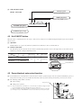
TECHNICAL MANUAL
Collection data
WALL MOUNTED TYPE
ROOM AIR-CONDITIONER
(Split system, air cooled cooling only type)
SRK52CF-BN, 71CF-BN
SRK52CF-BP, 71CF-BP
-
3-
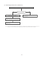
CONTENTS
1. GENERAL INFORMATION .............................................................................. 1
1.1 Specific features ....................................................................................... 1
1.2 How to read the model name ................................................................... 1
2. SELECTION DATA .......................................................................................... 2
2.1 Specifications ........................................................................................... 2
2.2 Range of usage & limitations .................................................................. 6
2.3 Exterior dimensions ................................................................................. 6
2.4 Piping system ........................................................................................... 8
2.5 Selection chart .......................................................................................... 9
3. ELECTRICAL DATA ........................................................................................ 10
3.1 Electrical wiring ........................................................................................ 10
4. OUTLINE OF OPERATION CONTROL BY MICROCOMPUTER ................... 14
4.1 Operation control function by remote control switch ........................... 14
4.2 Unit ON/OFF button .................................................................................. 16
4.3 Power blackout auto restart function ..................................................... 16
4.4 Custom cord switching procedure ......................................................... 17
4.5 Flap and louver control ............................................................................ 17
4.6 Comfortable timer setting ........................................................................ 18
4.7 Sleep timer operation ............................................................................... 18
4.8 Outline of cooling operation .................................................................... 19
4.9 Outline of dehumidifying operation ........................................................ 20
4.10 Outline of automatic operation ................................................................ 21
4.11 Set temperature selection ........................................................................ 21
4.12 Outline of fan operation ........................................................................... 22
4.13 Regulation of outdoor air flow ................................................................. 22
4.14 Stop mode ................................................................................................. 23
4.15 External control (remote display)/control of input signal ..................... 24
4.16 Operation permission/prohibition control .............................................. 25
4.17 Protective control function ...................................................................... 25
4.18 List of indoor unit jumper selections ...................................................... 28
5. APPLICATION DATA ....................................................................................... 29
5.1 Selection of location for installation ....................................................... 30
5.2 Installation of indoor unit ......................................................................... 31
5.3 Installation of outdoor unit ...................................................................... 34
5.4 Refrigerant piping ..................................................................................... 34
5.5 Test run ...................................................................................................... 36
5.6 Precautions for wireless remote control installation and operation ........ 36
5.7 Installation of wired remote control and super link
adapter (SC-AD-ER) (Optional parts) ...................................................... 37
6. MAINTENANCE DATA .................................................................................... 44
6.1 Troubleshooting procedures for electrical equipment ......................... 44
6.2 Servicing .................................................................................................... 52
-
1-
1
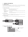
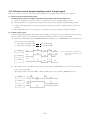
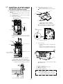
GENERAL INFORMATION
1.1 Specific features
The “MITSUBISHI HEAVY INDUSTRIES, LTD.” room air-conditioner: SRK series are of split and wall mounted type and the unit
consists of indoor unit and outdoor unit with refrigerant precharged in factory. The indoor unit is composed of room air cooling equipment with operation control switch and the outdoor unit is composed of condensing unit with compressor.
(1) Remote control flap & louver
The flap & louver can be automatically controlled by operating wireless remote control.
¡ Flap swing
: The flaps swing up and down successively.
¡ Louver swing
: The louvers swing left and right successively.
¡ Multi-directional Air Flow : Activating both up/down air swing and left/right air swing at the same time results in a multi(up/down air scroll and
directional air flow.
left/right air scroll)
¡ Memory flap
: Once the flap & louver position is set, the unit memorizes the position and continues to operate
at the same position from the next time.
(2) Automatic operation
When the remote control switch is set on “auto (
) ”, it will either automatically decide operation mode such as cooling and
thermal dry, or operate in the operation mode before it has been turned to automatic control.
(3) Self diagnosis function
¡
We are constantly trying to do better service to our customers by installing such judges that show abnormality of operation as
follows.
RUN light
1 time flash
TIMER light
ON
2 time flash
6 time flash
TIMER light
Heat exchanger sensor error
Room temperature sensor error
RUN light
keeps flashing
Indoor fan motor error
RUN light
ON
1 time flash
Outdoor temperature sensor error
2 time flash
Outdoor heat exchanger sensor
error
4 time flash
Discharge pipe temp. sensor error
2 time flash
Trouble of outdoor unit
5 time flash
Over heat of compressor
6 time flash
Error of signal transmission
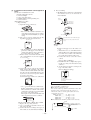
1.2 How to read the model name
Example :
SR K 52 C F - BN
Power supply
BN: 1 Phase 220-240V 50Hz
BP: 1 Phase 220V 60Hz
Series No.
Cooling only type
Product capacity
Wall mounted type
Split type room air-conditioner
-
1-
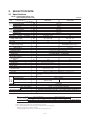
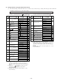
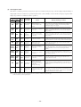
2. SELECTION DATA
2.1 Specifications
Model SRK52CF-BN (Indoor unit)
SRC52CF-BN (Outdoor unit)
(220/240V)
Model
SRK52CF-BN
Item
kW
ISO-T1
(JIS)
Cooling capacity
ISO-T3
(SASO)
Cooling power input
Energy efficiency ratio
Rating current
Cooling capacity
Cooling power input
Energy efficiency ratio
Rating current
Power source
Noise level
Cooling
Sound level
Exterior dimensions
Height × Width × Depth
Color
Net weight
Refrigerant equipment
Compressor type & Q’ty
Refrigerant
piping
Motor
Starting method
Heat exchanger
Refrigerant control
Refrigerant(3)
Refrigerant oil
Deice control
Air handling equipment
Fan type & Q’ty
Motor
Air flow (at High)
Air filter, Q’ty
Shock & vibration absorber
Electric heater
Operation control
Operation switch
Room temperature control
Pilot lamp
Safety equipment
5.4 / 5.4
kW
Btu/hW
A
kW
kW
Btu/hW
A
1.76 / 1.91
10.47 / 9.66
8.8 / 8.7
5.0 / 5.0
2.06 / 2.20
8.29 / 7.75
10.3 / 10.1
1 Phase, 220-240V, 50Hz
Hi 43, Me 40, Lo 37
dB
318 × 1098 × 248
640 × 850 × 290
kg
Yellowish white
15
Stucco white
46
–
2KS314D5AB04 (Rotary type) × 1
–
1.5
–
Line starting
Slit fins & inner grooved tubing
Straight fin & inner grooved tubing
Capillary tubes + Electric expansion valve
R22 1.25 (Pre-Charged up to the piping length of 7m)
0.67 (ATMOS NM56M or SUNISO 4DGID)
Microcomputer control
kg
R
W
(Cooling)
49
mm
kW
CMM
Tangential fan × 1
Propeller fan × 1
46
20
Polypropylene net (washable) × 2
–
–
35
38
–
Cushion rubber (for compressor)
–
Wireless-Remote control
–
Microcomputer thermostat
–
RUN (Green), TIMER (Yellow), HI POWER (Green), ECONO (Orange)
Compressor: overheat protection, Frost protection, Serial signal error protection, Indoor fan motor error
protection
O.D
Connecting method
Attached length of piping
Liquid line: φ6.35 (1/4″) Gas line: φ15.88 (5/8″)
Flare connecting
Liquid line: 0.70m
–
Gas line: 0.63m
Necessary (Both sides)
Connectable
Terminal block (Screw fixing type)
1.5 mm2 × 4 cores (Including earth cable)
Terminal block (Screw fixing type)
mm (in)
Insulation
Drain hose
Power source supply
Connection wiring
SRC52CF-BN
Size × Core number
Connecting method
Mounting kit, Clean filter (Natural enzyme filter × 1, Photocatalytic washable deodorizing filter × 1)
Wired-Remote control
Accessories (included)
Optional parts
Notes (1) The data are measured at the following conditions.
Item
Operation
Cooling
Indoor air temperature
Outdoor air temperature
DB
WB
DB
WB
27ºC
29ºC
19ºC
19ºC
35ºC
46ºC
24ºC
24ºC
The piping length is 7.5m.
(2) The operation data are applied to the 220/240V districts respectively.
(3) The refrigerant quantity to be charged includes the refrigerant in 7 m connecting piping.
(Purging is not required even in the short piping.)
If the piping length is longer, when it is 7 to 25m, add 25g refrigerant per meter.
-
2-
Standards
ISO-T1, JIS C9612
ISO-T3, SASO 385/386
Model SRK71CF-BN (Indoor unit)
SRC71CF-BN (Outdoor unit)
(220/240V)
Model
SRK71CF-BN
Item
ISO-T3
(SASO)
ISO-T1
(JIS)
Cooling capacity
Cooling power input
Energy efficiency ratio
Rating current
Cooling capacity
Cooling power input
Energy efficiency ratio
Rating current
Power source
Noise level
Cooling
Sound level
Exterior dimensions
Height × Width × Depth
Color
Net weight
Refrigerant equipment
Compressor type & Q’ty
Motor
Starting method
Heat exchanger
Refrigerant control
Refrigerant
piping
Refrigerant(3)
Refrigerant oil
Deice control
Air handling equipment
Fan type & Q’ty
Motor
Air flow (at High)
Air filter, Q’ty
Shock & vibration absorber
Electric heater
Operation control
Operation switch
Room temperature control
Pilot lamp
Safety equipment
kW
kW
Btu/hW
A
kW
kW
Btu/hW
A
7.03 / 7.03
2.12 / 2.27
11.33 / 10.58
10.6 / 10.4
6.3 / 6.3
2.48 / 2.60
8.67 / 8.26
12.4 / 11.9
1 Phase, 220-240V, 50Hz
Hi 45, Me 42, Lo 39
dB
318 × 1098 × 248
750 × 880 × 340
kg
Yellowish white
15
Stucco white
67
–
2JS386D5BC02 (Rotary type) × 1
kW
–
1.8
–
Line starting
Slit fins & inner grooved tubing
Straight fin & inner grooved tubing
Capillary tubes + Electric expansion valve
R22 1.75 (Pre-charged up to the piping length of 7m)
0.7 (ATMOS NM56M or SUNISO 4GDID)
Microcomputer control
W
CMM
Tangential fan × 1
Propeller fan × 1
46
20.5
Polypropylene net (washable) × 2
–
–
85
60
–
Cushion rubber (for compressor)
–
Wireless-Remote control
–
Microcomputer thermostat
–
RUN (Green), TIMER (Yellow), HI POWER (Green), ECONO (Orange)
Compressor: overheat protection, Frost protection, Serial signal error protection, Indoor fan motor error
protection
O.D
Connecting method
Attached length of piping
Liquid line: φ6.35 (1/4″) Gas line: φ15.88 (5/8″)
Flare connecting
Liquid line: 0.70m
–
Gas line : 0.63m
Necessary (Both sides)
Connectable
Terminal block (Screw fixing type)
1.5 mm2 × 4 cores (Including earth cable)
Terminal block (Screw fixing type)
mm (in)
Insulation
Drain hose
Power source supply
Connection wiring
55
mm
kg
R
(Cooling)
SRC71CF-BN
Size × Core number
Connecting method
Mounting kit, Clean filter (Natural enzyme filter × 1, Photocatalytic washable deodorizing filter × 1)
Wired-Remote control
Accessories (included)
Optional parts
Notes (1) The data are measured at the following conditions.
Item
Operation
Cooling
Indoor air temperature
Outdoor air temperature
DB
WB
DB
WB
27ºC
29ºC
19ºC
19ºC
35ºC
46ºC
24ºC
24ºC
The piping length is 7.5m.
(2) The operation data are applied to the 220/240V districts respectively.
(3) The refrigerant quantity to be charged includes the refrigerant in 7 m connecting piping.
(Purging is not required even in the short piping.)
If the piping length is longer, when it is 7 to 25m, add 25g refrigerant per meter.
-
3-
Standards
ISO-T1, JIS C9612
ISO-T3, SASO 385/386
Model SRK52CF-BP (Indoor unit)
SRC52CF-BP (Outdoor unit)
(220V)
Model
SRK52CF-BP
Item
ISO-T1
(JIS)
Cooling capacity
ISO-T3
(SASO)
Cooling power input
Energy efficiency ratio
Rating current
Cooling capacity
Cooling power input
Energy efficiency ratio
Rating current
Power source
Noise level
Cooling
Sound level
Exterior dimensions
Height × Width × Depth
Color
Net weight
Refrigerant equipment
Compressor type & Q’ty
Motor
Starting method
Heat exchanger
Refrigerant control
Refrigerant
piping
Refrigerant(3)
Refrigerant oil
Deice control
Air handling equipment
Fan type & Q’ty
Motor
Air flow (at High)
Air filter, Q’ty
Shock & vibration absorber
Electric heater
Operation control
Operation switch
Room temperature control
Pilot lamp
Safety equipment
kW
5.4
kW
Btu/hW
A
kW
kW
Btu/hW
A
1.76
10.47
8.8
5.0
2.06
8.29
10.3
1 Phase, 220V, 60Hz
dB
Hi 43, Me 40, Lo 37
49
mm
318 × 1098 × 248
640 × 850 × 290
kg
Yellowish white
15
Stucco white
46
–
2KS252H5AB04 (Rotary type) × 1
kW
–
1.2
–
Line starting
Slit fins & inner grooved tubing
Straight fin & inner grooved tubing
Capillary tubes + Electric expansion valve
kg
R
R22 1.25 (Pre-Charged up to the piping length of 7m)
0.65 (ATMOS NM56M or SUNISO 4GDID)
Microcomputer control
W
(Cooling)
SRC52CF-BP
CMM
Tangential fan × 1
Propeller fan × 1
46
20
Polypropylene net (washable) × 2
–
–
29
38
–
Cushion rubber (for compressor)
–
Wireless-Remote control
–
Microcomputer thermostat
–
RUN (Green), TIMER (Yellow), HI POWER (Green), ECONO (Orange)
O.D
Connecting method
Attached length of piping
mm (in)
Compressor: overheat protection, Frost protection, Serial signal error protection, Indoor fan motor error
protection
Liquid line: φ6.35 (1/4″) Gas line: φ15.88 (5/8″)
Flare connecting
Liquid line: 0.70m
Gas line: 0.63m
Insulation
Drain hose
Power source supply
–
Necessary (Both sides)
Connectable
Terminal block (Screw fixing type)
1.5 mm2 × 4 cores (Including earth cable)
Terminal block (Screw fixing type)
Mounting kit, Clean filter (Natural enzyme filter × 1, Photocatalytic washable deodorizing filter × 1)
Wired-Remote control
Size × Core number
Connecting method
Accessories (included)
Optional parts
Connection wiring
Notes (1) The data are measured at the following conditions.
Item
Operation
Cooling
Indoor air temperature
Outdoor air temperature
DB
WB
DB
WB
27ºC
29ºC
19ºC
19ºC
35ºC
46ºC
24ºC
24ºC
The piping length is 7.5m.
(2) The operation data are applied to the 220V districts respectively.
(3) The refrigerant quantity to be charged includes the refrigerant in 7 m connecting piping.
(Purging is not required even in the short piping.)
If the piping length is longer, when it is 7 to 25m, add 25g refrigerant per meter.
-
4-
Standards
ISO-T1, JIS C9612
ISO-T3, SASO 385/386
Model SRK71CF-BP (Indoor unit)
SRC71CF-BP (Outdoor unit)
(220V)
Model
SRK71CF-BP
Item
Refrigerant
piping
ISO-T3
(SASO)
ISO-T1
(JIS)
Cooling capacity
Cooling power input
Energy efficiency ratio
Rating current
Cooling capacity
Cooling power input
Energy efficiency ratio
Rating current
Power source
Noise level
Cooling
Sound level
Exterior dimensions
Height × Width × Depth
Color
Net weight
Refrigerant equipment
Compressor type & Q’ty
Motor
Starting method
Heat exchanger
Refrigerant control
Refrigerant(3)
Refrigerant oil
Deice control
Air handling equipment
Fan type & Q’ty
Motor
Air flow (at High)
(Cooling)
Air filter, Q’ty
Shock & vibration absorber
Electric heater
Operation control
Operation switch
Room temperature control
Pilot lamp
Safety equipment
O.D
Connecting method
Attached length of piping
kW
kW
Btu/hW
A
kW
kW
Btu/hW
A
SRC71CF-BP
7.03
2.12
11.33
10.6
6.3
2.48
8.67
12.4
1 Phase, 220V, 60Hz
dB
Hi 45, Me 42, Lo 39
55
mm
318 × 1098 × 248
750 × 880 × 340
kg
Yellowish white
15
Stucco white
67
–
2JS318H5AB02(Rotary type) × 1
kW
–
1.5
–
Line starting
Slit fins & inner grooved tubing
Straight fin & inner grooved tubing
Capillary tubes + Electric expansion valve
R22 1.75 (Pre-charged up to the piping length of 7m)
0.7 (ATMOS NM56M or SUNISO 4GDID)
Microcomputer control
kg
R
W
CMM
Tangential fan × 1
Propeller fan × 1
46
20.5
Polypropylene net (washable) × 2
–
–
73
60
–
Cushion rubber (for compressor)
–
Wireless-Remote control
–
Microcomputer thermostat
–
RUN (Green), TIMER (Yellow), HI POWER (Green), ECONO (Orange)
Compressor: overheat protection, Frost protection, Serial signal error protection, Indoor fan motor error
protection
mm (in)
Insulation
Drain hose
Power source supply
Size × Core number
Connecting method
Accessories (included)
Optional parts
Connection wiring
Liquid line: φ6.35 (1/4″) Gas line: φ15.88 (5/8″)
Flare connecting
Liquid line: 0.70m
–
Gas line : 0.63m
Necessary (Both sides)
Connectable
Terminal block (Screw fixing type)
1.5 mm2 × 4 cores (Including earth cable)
Terminal block (Screw fixing type)
Mounting kit, Clean filter (Natural enzyme filter × 1, Photocatalytic washable deodorizing filter × 1)
Wired-Remote control
Notes (1) The data are measured at the following conditions.
Item
Operation
Cooling
Indoor air temperature
Outdoor air temperature
DB
WB
DB
WB
27ºC
29ºC
19ºC
19ºC
35ºC
46ºC
24ºC
24ºC
The piping length is 7.5m.
(2) The operation data are applied to the 220V districts respectively.
(3) The refrigerant quantity to be charged includes the refrigerant in 7 m connecting piping.
(Purging is not required even in the short piping.)
If the piping length is longer, when it is 7 to 25m, add 25g refrigerant per meter.
-
5-
Standards
ISO-T1, JIS C9612
ISO-T3, SASO 385/386
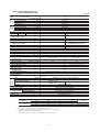
2.2 Range of usage & limitations
Models
All models
Item
Indoor return air temperature
(Upper, lower limits)
Cooling operation: Approximately 21 to 32 °C
Outdoor air temperature
(Upper, lower limits)
Cooling operation: Approximately 21 to 54 °C
Refrigerant line (one way) length
Max. 25m
Vertical height difference between
outdoor unit and indoor unit
Max. 15m
Rating ± 10%
Power source voltage
Voltage at starting
Min. 85% of rating
Frequency of ON-OFF cycle
Max. 10 times/h
ON and OFF interval
Max. 3 minutes
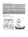
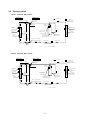
2.3 Exterior dimensions
(1) Indoor unit
Models SRK52CF-BN, 71CF-BN, 52CF-BP, 71CF-BP
Unit: mm
A
1098
248
3
9 48
318
Piping hole right (left)
Terminal block 55
Indoor unit
886
450
49.5
50
Installation board
106
299
50
150
349
8.5
106
60
44.5
301.8
25
4
19
17.3
1090
51.2
64
4
43.5
55
77
55
53.5
7.7
44.5
47
221.5
25
Piping for Gas (ø15.88) 633.5
Piping for Liquid (ø6.35) 703.5
Drain hose 772 (ø16)
Piping hole (ø65)
Piping hole (ø65)
VIEW A
-
6-
(2) Outdoor unit
Models SRC52CF-BN, 52CF-BP
50
Drain holes
12
Unit: mm
14
49.6
314
290
43.5
12
328
286.4
476
203.1
510
Elogated hole
(2-12 x16)
136.9
850
Terminal block
640
124
34.6
42.7
Ground
terminal
100.3
15
20˚
20˚
Service valve (Liquid)
ø6.35 (1/4'')
Service valve (Gas)
ø15.88 (5/8'')
Models SRC71CF-BN, 71CF-BP
Unit: mm
223
310
60
15
2-
R7
61
150
Drain holes
580
27
150
880
418
19
61
380
340
47.5
.5
32
88
Terminal block
Service valve (Liquid)
24
30°
48.5
750
Flare fitting ø6.35(1/4")
Service valve(Gas)
103.5
Flare fitting ø15.88(5/8")
165.5
-
7-
25
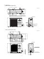
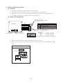
2.4 Piping system
Models SRK52CF-BN, 52CF-BP
Indoor unit
Outdoor unit
Flare connecting
Piping
(Gas)
ø15.88
Cooling cycle
Outdoor air
temp. sensor
Service valve
(Gas)
Muffler*
Check joint
Heat exchanger
sensor
Humidity
sensor
Room temp.
sensor
Heat
exchanger
Discharge pipe
temp. sensor
Heat
exchanger
sensor
Heat
exchanger
Compressor
Piping
(Liquid)
ø6.35
Accumulator
Service valve (Liquid)
Capillary tube
Electronic
expansion valve
Strainer
Flare connecting
Capillary tube
* except for 52CF-BN
Models SRK71CF-BN, 71CF-BP
Indoor unit
Outdoor unit
Flare connecting
Piping
(Gas)
ø15.88
Cooling cycle
Outdoor air
temp. sensor
Service valve
(Gas)
Muffler*
Check joint
Humidity
sensor
Room temp.
sensor
Heat exchanger
sensor
Heat
exchanger
sensor
Heat
exchanger
Discharge pipe
temp. sensor
Heat
exchanger
Compressor
Piping
(Liquid)
ø6.35
Accumulator
Service valve (Liquid)
Capillary tube
Flare connecting
Electronic
expansion valve
Strainer
* except for 71CF-BP
-
8-
Strainer
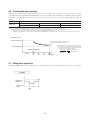
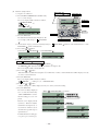
2.5 Selection chart
Correct the cooling capacity in accordance with the conditions as follows. The net cooling capacity can be obtained in the following way.
Net capacity = Capacity shown on specification ✕ Correction factors as follows.
(1) Coefficient of cooling capacity in relation to temperatures
S SRK52CF-BN, 52CF-BP
Coefficient of cooling
capacity in
relation to temperature
1.3
1.2
Cooling
1.1
1.0
0.9
0.8
0.7
Outdoor air D.B.
temperature
°C D.B.
Cooling operation
0.6
ISO-T3
Standard Condition
ISO-T1
Standard Condition
Applicable range
54
50
45
40
35
30
25
21
16
18
20
24
22
Indoor air W.B. temperature °C W.B.
S SRK71CF-BN, 71CF-BP
Coefficient of cooling
capacity in
relation to temperature
1.3
1.2
Cooling
1.1
1.0
0.9
0.8
0.7
Outdoor air D.B.
temperature
°C D.B.
Cooling operation
0.6
ISO-T3
Standard Condition
ISO-T1
Standard Condition
Applicable range
54
50
45
40
35
30
25
21
16
18
20
22
24
Indoor air W.B. temperature °C W.B.
(2) Correction of cooling capacity in relation to one way length of refrigerant piping
It is necessary to correct the cooling capacity in relation to the one way piping length between the indoor and outdoor units.
Piping length [m]
7
10
15
20
25
Cooling
1.0
0.99
0.975
0.965
0.95
How to obtain the cooling capacity
Example : The net cooling capacity of the model SRK71CF-BN with the piping length of 15m, indoor wet-bulb temperature at 19.0˚C
and outdoor dry-bulb temperature 35˚C is Net cooling capacity =
7030
✕
SRK71CF-BN
-
9-
0.975
Length 15m
✕
1.0
=
Factor by air
temperatures
6854 W
HA
JEM-A
S/N
R/L
1
L
G
Power Source
1 Phase
220-240V 50Hz
J
J
BK
RD
WH
N
RD
Y/GN
BK
WH
1
2/N
N
F
250V
3.15A
CC
CM2 WH
Option
ZNR
XR1
XR2
XR3
XR4
CNT
CM1 BK
F
250V
3.15A
52X1
Y
10 -
CNX
CNM
CNE
CNG
~
~
-
+
DS
11
9
CNB
52X3
RD
WH
BK
-
CNY
52X4
CNF
BL
XYZ
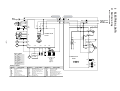
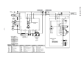
Parts name
Compressor motor
Fuse
Fan motor(Indoor)
Fan motor(Outdoor)
Flap motor
Louver motor
Room temp.sensor
Heat exch.sensor(Indoor unit)
WH
CNU
Display
SM
Wireless
R-AMP
Th1 Th2 Th3
Terminal block
Printed circuit
board
To wired
remote
control
(Option)
CNE
EEV
52X1 52X3 52X4
Th4
Meaning of marks
CM
F
FMI
FMO
SM
LM1,2
Th1
Th2
FMo
3
CNG
Symbol
OR
Y
RD
7
5
Color symbol
Black
Blue
Orange
Red
Yellow
White
Yellow/Green
Green
CFO
Y
XYZ
BK
BL
OR
RD
Y
WH
Y/G
GR
CM
W
Printed circuit
board
XR5
LM1
U
V
ZNR
LM2
WH
RD
L
Th5
Th6
Symbol
Th3
Th4
Th5
Th6
ZNR
EEV
DS
52X1~4
Parts name
Humidity sensor
Heat exch.sensor(Outdoor unit)
Outdoor air temp.sensor
Discharge pipe temp.sensor
Varistor
Electronic expansion valve
Diode stack
Auxiliary relay
Symbol
CC
CFO
TB
XR1
XR2
XR3
XR4
XR5
Parts name
Capacitor for CM
Capacitor for FMO
Terminal block
Operation indication (DC12)
Heating indication (DC12)
ON indication for CM(DC12)
Check indication (DC12)
Distant operation
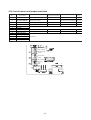
ELECTRICAL DATA
FMI
6
5
4
3
1
CNU
Y/GN
3
3
BL
Y
WH
BK
RD
Y/GN
RD
3
WH
2/N
BK
TB
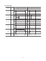
3.1 Electrical wiring
Heat
exchanger
TB
Model SRK52-CF-BN
Outdoor unit
Indoor unit
Option
HA
JEM-A
XR1
XR2
XR3
XR4
S/N
R/L
Y/GN
G
2/N
N
1
L
J
N
F
250V
3.15A
CC
CM1 BK
F
250V
3.15A
52X1
Y
CNY
11 -
CNG
CNF
CNB
~
-
+
DS
11
9
52X3
RD
WH
BK
CNE
~
XY Z
Wireless
R-AMP
Black
Blue
Orange
Red
Yellow
White
Yellow/Green
Green
Th3
1
5
Terminal block
To wired
remote
control
(Option)
CNE
Parts name
Compressor motor
Fuse
Fan motor(Indoor)
Fan motor(Outdoor)
Flap motor
Louver motor
Room temp.sensor
Heat exch.sensor(Indoor unit)
EEV
52X1 52X3 52X4 52X5
Th4
Meaning of marks
CM
F
FMI
FMO
SM
LM1,2
Th1
Th2
WH
CNU
Printed circuit
board
CNG
Symbol
FMo
3
BK
52X5
Th2
7
XYZ
Display
Th1
OR
Y
RD
BL
52X4
BK
BL
OR
RD
Y
WH
Y/G
GR
CFO
Y
CNX
Color symbol
CM
W
Printed circuit
board
ZNR
SM
U
CM2 WH
V
CNT
CNM
WH
RD
L
ZNR
LM1
BK
RD
J
XR5
LM2
Power Source
1 Phase
220-240V 50Hz
3
RD
Y/GN
1
BK
FMI
6
5
4
3
1
CNU
WH
BL
Y
WH
BK
RD
TB
WH
Y/GN
RD
3
WH
2/N
BK
Heat
exchanger
TB
Th5
Th6
Symbol
Th3
Th4
Th5
Th6
ZNR
EEV
DS
52X1~5
Parts name
Humidity sensor
Heat exch.sensor(Outdoor unit)
Outdoor air temp.sensor
Discharge pipe temp.sensor
Varistor
Electronic expansion valve
Diode stack
Auxiliary relay
Symbol
CC
CFO
TB
XR1
XR2
XR3
XR4
XR5
Parts name
Capacitor for CM
Capacitor for FMO
Terminal block
Operation indication (DC12)
Heating indication (DC12)
ON indication for CM(DC12)
Check indication (DC12)
Distant operation
Model SRK71CF-BN
Outdoor unit
Indoor unit
HA
JEM-A
S/N
R/L
Y/GN
G
Power Source
1 Phase
220V 60Hz
3
2/N
N
1
L
J
J
BK
RD
RD
Y/GN
1
BK
FMI
6
5
4
3
1
CNU
WH
BL
Y
WH
BK
RD
Y/GN
RD
3
WH
2/N
BK
TB
WH
Heat
exchanger
TB
N
F
250V
3.15A
CC
CM2 WH
Option
ZNR
XR1
XR2
XR3
XR4
W
F
250V
3.15A
52X1
Y
XR5
CNY
12 -
CNX
CNM
CNE
CNG
~
-
+
DS
11
9
52X3
52X4
BL
XYZ
Parts name
Compressor motor
Fuse
Fan motor(Indoor)
Fan motor(Outdoor)
Flap motor
Louver motor
Room temp.sensor
Heat exch.sensor(Indoor unit)
WH
CNU
Display
SM
Wireless
R-AMP
Th1 Th2 Th3
Terminal block
Printed circuit
board
To wired
remote
control
(Option)
CNE
EEV
52X1 52X3 52X4
Th4
Meaning of marks
CM
F
FMI
FMO
SM
LM1,2
Th1
Th2
FMo
3
CNG
Symbol
OR
Y
RD
7
5
Color symbol
Black
Blue
Orange
Red
Yellow
White
Yellow/Green
Green
~
CNB
CNF
XYZ
BK
BL
OR
RD
Y
WH
Y/G
GR
CFO
Y
RD
WH
BK
-
LM1
CM
CM1 BK
ZNR
LM2
U
V
Printed circuit
board
CNT
WH
RD
L
Th5
Th6
Symbol
Th3
Th4
Th5
Th6
ZNR
EEV
DS
52X1~4
Parts name
Humidity sensor
Heat exch.sensor(Outdoor unit)
Outdoor air temp.sensor
Discharge pipe temp.sensor
Varistor
Electronic expansion valve
Diode stack
Auxiliary relay
Symbol
CC
CFO
TB
XR1
XR2
XR3
XR4
XR5
Parts name
Capacitor for CM
Capacitor for FMO
Terminal block
Operation indication (DC12)
Heating indication (DC12)
ON indication for CM(DC12)
Check indication (DC12)
Distant operation
Model SRK52CF-BP
Outdoor unit
Indoor unit
Option
HA
JEM-A
XR1
XR2
XR3
XR4
S/N
R/L
Y/GN
G
2/N
N
1
L
J
N
F
250V
3.15A
CC
CM1 BK
F
250V
3.15A
52X1
Y
CNY
13 -
CNG
CNF
CNB
~
-
+
DS
11
9
52X3
RD
WH
BK
CNE
~
XY Z
Wireless
R-AMP
Black
Blue
Orange
Red
Yellow
White
Yellow/Green
Green
Th3
1
5
Terminal block
To wired
remote
control
(Option)
CNE
Parts name
Compressor motor
Fuse
Fan motor(Indoor)
Fan motor(Outdoor)
Flap motor
Louver motor
Room temp.sensor
Heat exch.sensor(Indoor unit)
EEV
52X1 52X3 52X4 52X5
Th4
Meaning of marks
CM
F
FMI
FMO
SM
LM1,2
Th1
Th2
WH
CNU
Printed circuit
board
CNG
Symbol
FMo
3
BK
52X5
Th2
7
XYZ
Display
Th1
OR
Y
RD
BL
52X4
BK
BL
OR
RD
Y
WH
Y/G
GR
CFO
Y
CNX
Color symbol
CM
W
Printed circuit
board
ZNR
SM
U
CM2 WH
V
CNT
CNM
WH
RD
L
ZNR
LM1
BK
RD
J
XR5
LM2
Power Source
1 Phase
220V 60Hz
3
RD
Y/GN
1
BK
FMI
6
5
4
3
1
CNU
WH
BL
Y
WH
BK
RD
TB
WH
Y/GN
RD
3
WH
2/N
BK
Heat
exchanger
TB
Th5
Th6
Symbol
Th3
Th4
Th5
Th6
ZNR
EEV
DS
52X1~5
Parts name
Humidity sensor
Heat exch.sensor(Outdoor unit)
Outdoor air temp.sensor
Discharge pipe temp.sensor
Varistor
Electronic expansion valve
Diode stack
Auxiliary relay
Symbol
CC
CFO
TB
XR1
XR2
XR3
XR4
XR5
Parts name
Capacitor for CM
Capacitor for FMO
Terminal block
Operation indication (DC12)
Heating indication (DC12)
ON indication for CM(DC12)
Check indication (DC12)
Distant operation
Model SRK71CF-BP
Outdoor unit
Indoor unit
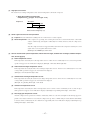
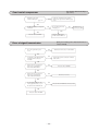
4. OUTLINE OF OPERATION CONTROL BY MICROCOMPUTER
4.1 Operation control function by remote control switch
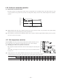
(1) Wireless remote control
Models All models
S Operation section
FAN SPEED button
Each time the button is pushed, the
cator is switched over in turn.
OPERATION MODE select button
indi-
Each time the button is pushed, the
cator is switched over in turn.
indi-
ON/OFF (luminous) button
HI POWER/ECONO button
Press for starting operation, press again for
stopping.
This button changes the HIGH POWER/
ECONOMY mode.
AIR FLOW (UP/DOWN) button
TEMPERATURE button
This button changes the air flow (up/down)
mode.
This button sets the room temperature.
(This button changes the present time and
TIMER time.)
AIR FLOW (LEFT/RIGHT) button
This button changes the air flow (left/right)
mode.
SLEEP button
This button selects SLEEP operation.
CANCEL button
This button cancels the ON timer, OFF
timer, and SLEEP operation.
CLEAN switch
OFF TIMER button
This switch changes the CLEAN mode.
This button selects OFF TIMER operation.
ON TIMER button
RESET switch
This button selects ON TIMER operation.
Switch for resetting microcomputer.
TIME SET UP switch
This switch for setting the time.
• The above illustration shows all controls, but in practice
only the relevant parts are shown.
S Indication section
ON/OFF TIMER indicator
Indicates during ON/OFF TIMER operation.
SLEEP indicator
Indicates during SLEEP operation.
OPERATION MODE indicator
Indicates selected operation with lamp.
[
(Auto) •
(Cool) •
(Fan) • (Dry)]
TEMPERATURE indicator
Indicates set temperature.
(Does not indicate temperature when operation
mode is on AUTO)
FAN SPEED indicator
Indicates set air flow rate with
TIME indicator
lamp.
Indicates present time or timer setting time.
AIR FLOW indicator
CLEAN indicator
Shows selected flap and louver mode.
Indicates during CLEAN operation.
HI POWER/ ECONO MODE indicator
Indicates during High power/economy mode
operation.
-
14 -
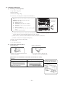
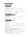
(2) Wired remote control (Optional parts)
The figure below shows the remote control with the cover opened. Note that all the items that may be displayed in the liquid crystal display
area are shown in the figure for the sake of explanation.
Characters displayed with dots in the liquid crystal display area are abbreviated.
Note (1) The SRK models don't support the switches and functions displayed in [ ].
Pull the cover downward to open it.
Central control display
[Vent indicator]
Displayed when the air conditioning
system is controlled by the option controller.
Indicates operation in the
ventilation mode.
Weekly timer display
Displays the settings of
the weekly timer.
Timer operation display
Displays the settings related to
timer operation.
Operation setting display area
Temperature setting switches
Operation/Check indicator light
These switches are used to set
the temperature of the room.
During operation: Lit in green
In case of error: Flashing in red
TIMER switch
Operation/Stop switch
This switch is used to select
a timer mode.
(The comfortable timer or sleep
operation cannot be selected.)
This switch is used to operate and
stop the air conditioning system.
Press the switch once to operate
the system and press it once again to
stop the system.
Displays setting temperature,
airflow volume, operation mode and
operation message.
MODE switch
This switch is used to switch between
operation modes.
(The clean operation cannot be selected.)
FAN SPEED switch
Timer setting switches
This switch is used to set the
airflow volume.
(AUTO, HI POWER or ECONO
cannot be selected.)
These switches are used to set
the timer mode and time.
[VENT switch]
Switch that operates the
connected ventilator.
[GRILL switch]
This switch has no function.
When this switch is pressed,
(Invalid Operation)
is displayed, but it does not mean a failure.
LOUVER switch
This switch is used to operate/stop
the swing louver.
(UP/down swing only)
AIR CON No. (Air conditioning system No.) switch
Displays the number of the connected
air conditioning system.
("00" appears.)
SET switch
This switch is used at servicing.
This switch is used to apply the timer
operation setting.
This switch is also used to make silent
mode operation settings.
[TEST switch]
[RESET switch]
This switch is used during test operation.
Press this switch while making settings
to go back to the previous operation.
This switch is also used to reset the
FILTER CLEANING message display.
(Press this switch after cleaning the air filter.)
[CHECK switch]
* If you press any of the switches above and
But it does not mean a failure.
INVALID OPER is display, the switch has no function.
-
15 -
(3) Unit indication section
RUN light (green)
Models All models
• Illuminates during operation.
TIMER light (yellow)
Illuminates during TIMER operation.
HI POWER light (green)
Illuminates during HIGH POWER operation.
ECONOMY light (orange)
Illuminates during ECONOMY operation.
4.2 Unit ON/OFF button
When the remote control batteries become weak, or if the remote control is lost or malfunctioning, this button may be used to turn the
unit on and off.
(1) Operation
Push the button once to place the unit in the automatic mode. Push it once more to turn the unit off.
(2) Details of operation
The unit will go into the automatic mode in which it automatically determines, from room temperature (as detected by sensor),
whether to go into the cooling or thermal dry modes.
Function
Operation mode
Room temperature
setting
Cooling
About 24ºC
Thermal dry
About 24ºC
Fan speed
Flap
Timer switch
Auto
Auto
Continuous
Unit ON/OFF button
4.3 Power blackout auto restart function
(1)
Power blackout auto restart function is a function that records the operational status of the air-conditioner immediately prior to it
being switched off by a power cut, and then automatically resumes operations at that point after the power has been restored.
(2)
The following settings will be cancelled:
(a) Timer settings
Jumper wire (J7)
(b) High-power operations
EXTERNAL INPUT
WIRED REMOCON
Notes (1) The power blackout auto restart function is set at on when the air-conditioner is shipped from the
factory. Consult with your dealer if this function needs to be switched off.
(2) When power failure ocurrs, the timer setting is cancelled. Once power is resumed, reset the timer.
(3) If the jumper wire (J7) “AUTO RESTART” is cut, auto restart is disabled. (See the diagram at right)
OPE PERMISSION
CUSTOM
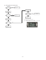
AUTO RESTART
LO TEMP
DIRT PREVENT
COOL ONLY
HI CEIL
PANEL
50/60
-
16 -
4.4 Custom cord switching procedure
If two wireless remote controls are installed in one room, in order to prevent wrong
EXTERNAL INPUT
WIRED REMOCON
operation due to mixed signals, please modify the printed circuit board in the indoor
OPE PERMISSION
CUSTOM
unit’s control box and the remote control using the following procedure. Be sure to modify
Jumper wire (J4)
AUTO RESTART
LO TEMP
both boards. If only one board is modified, receiving (and operation) cannot be done.
DIRT PREVENT
COOL ONLY
(1) Modifying the indoor unit’s printed circuit board
HI CEIL
PANEL
Take out the printed circuit board from the control box and cut off jumper wire (J4) using
50/60
wire cutters.
After cutting of the jumper wire, take measures to prevent contact with the other the
lead wires, etc.
(2) Modifying the wireless remote control
Cut
1) Remove the battery.
2) Cut the jumper wire shown in the figure at right.
4.5 Flap and louver control
Control the flap and louver by AIRFLOW (LEFT/RIGHT) button on the wireless remote control.
(UP/DOWN) and
(1) Swing flap
Flap moves in upward and downward directions continuously.
(2) Swing louver
Louver moves in left and right directions continuously.
(3) When not operating
The flap returns to the position of air flow directly below, when operation has stopped.
(4) Multi-directional Air Flow (up/down air scroll and left/right air scroll)
Activating both up/down air swing and left/right air swing at the same time results in a multi-directional air flow.
Up/down air scroll
Left/right air scroll
In COOL, DRY and FAN operation
In COOL, DRY and FAN operation
Stops at this position
for 5 seconds.
Thick line
Thin line
: moves quickly
: moves slowly
Left louver
Right louver
(5) Memory flap (Flap or Louver stopped)
When you press the AIRFLOW (UP/DOWN or LEFT/RIGHT) button once while the flap or louver is operating, it stops swinging
at an angle. Since this angle is memorized in the micro-computer, the flap or louver will automatically be set at this angle when the
next operation is started.
¡ Recommendable stopping angle of the flap
COOL•DRY
Horizontal
blowing
-
17 -
4.6 Comfortable timer setting
If the timer is set at ON when the operation select switch is set at the cooling, or the cooling in auto mode operation is selected, the
comfortable timer starts and determines the starting time of next operation based on the initial value of 15 minutes and the relationship
between the room temperature at the setting time (temperature of room temperature sensor) and the setting temperature. (Max. 60
minutes)
Operation mode
Operation start time correction value (Min.)
3 < Room temp. – Setting temp.
1 < Room temp. – Setting temp. =
≤3
Room temp. – Setting temp. =
≤1
+5
No change
–5
At cooling
Notes (1) At 5 minutes before the timer ON time, operation starts regardless of the temperature of the room temperature sensor (Th1).
(2) This function does not actuate when the operation select switch is set at the dehumidifying as well as the dehumidifying in the auto mode.
However, the operation of item (1) above is performed during the dehumidifying in the auto mode.
(3) During the comfortable timer operation, both the run light and timer light illuminate and the timer light goes off after expiration of the timer, ON setting time.
(Example) Cooling
Room temperature
Corrects the starting time of next operation by
calculating the temperature difference.
¡ If the difference (= Room temperature – Setting temperature) is 4ºC, the correction value is found to be +5 minutes from the table shown above so that the starting time
of next operation is determined as follows:
15 min. earlier + 5 min. = 20 min. earlier
↑
↑
Correction value
Current operation
start time
Setting temperature
Operation starting time
Time
15 min.
earlier
10 min.
earlier
5 min.
earlier
Setting time
4.7 Sleep timer operation
Pressing the SLEEP button causes the temperature to be controlled as shown in the following chart with respect to the set temperature.
Cooling
+1.0
Temperature
setting (˚C)
0
-1.0
Timer operation
(time)
0
1.0
2.0
Start
-
18 -
4.8 Outline of cooling operation
(1) Operation of major functional components
Item
When the compressor
command is OFF
When the compressor
command is ON
When the compressor goes
OFF due to an anomalous stop.
ON
ON
OFF
Flap and louver
ON or OFF
ON or OFF
Stop position control
Display
Lights up
Lights up
Lights up or flashes
Functional
components
Indoor fan motor
Outdoor fan motor
Electric expansion valve
ON
Depending on the stop mode
Depending on the EEV control
Depending on the stop mode
(2) Fan speed switching
Fan speed switching
AUTO
Flow control
Air scroll
Swing flap or louver
Auto fan control
Swing stop
(i)
HIGH
MED
LOW
Speed 8
Speed 6
Speed 4
Speed 8
Speed 6
Speed 4
Speed 8
Speed 6
Speed 4
Auto fan control
The indoor fan is automatically controlled in accordance with the difference between the room temperature (detected by the
room temperature sensor) and the termostat setting as shown below.
Speed 8
Speed 6
Speed 4
+1
Thermostat setting point
+2
+3
+4
(3) Thermostat operation
The compressor and outdoor fan and turned on and off as shown below according to the temperature setting.
ON
Compressor
Outdoor fan
OFF
-1
Room temp. Set temp.
(4) HIGH POWER operation ( “HI POWER” button on the remote control : ON)
The following operation is performed for 15 minutes without relation to the set temperature or fan speed setting.
Indoor unit fan
Speed 9 fixed
Outdoor unit fan
ON
Compressor
ON
Notes (1) Room temperature is not adjusted during the HIGH POWER operation.
(2) Protective functions will actuate with priority even during the HIGH POWER
operation.
(5) ECONOMY operation ( “ECONO” button on the remote control : ON)
The set temperature changes as shown at right, and the
indoor unit fan speed is set on speed 4.
-
Running time
Set temperature compensation
Running start ~ 1 hour
Set temperature +0.5
1~2 hours
Set temperature +1.0
2 hours ~
Set temperature +1.5
19 -
4.9 Outline of dehumidifying operation
(1) Choose the appropriate operation block area by the difference between room temperature and thermostat
setting temperature as shown below.
¡ Operation block area
D Block
C Block
–2
Room temp.
B Block
A Block
0
+3
– Setting temp.(deg)
(2) Start up operation
C.D Block
A.B Block
Compressor ON
and
outdoor fan OFF
Compressor ON
and
outdoor fan OFF
Speed 4
Speed 4
Speed 1
Indoor fan
OFF
20
seconds
0
3
6
Start
9
Indoor fan
OFF
0
12 minutes
12 minutes
Start
Temperature check
Temperature check
Operation block decision
Note (1) Thermostat operation is performed in A, B Block. When compressor and indoor fan stop by thermostat operation within 12 minutes from start, temperature
check is performed by operating indoor fan at speed 1 for 20 seconds before finishing 12 minutes and allowing decision of next operation block.
(3) DRY operation
After finishing start up operation described in (2) above, thermal dry operation is performed at 8 minutes intervals, according to the
difference between room temperature and thermostat setting temperature as shown below.
Beside, 1 cycle of this operating time consists of 8 minutes, 7 cycle operation is performed then.
D Block
C Block
Compressor ON
and
outdoor fan OFF
Compressor ON
and
outdoor fan OFF
Speed 4
Speed 1
Speed 1
Indoor fan
OFF
20
seconds
0
4
Start
Indoor fan
OFF
20
seconds
8 minutes
0
Temperature check
3
8 minutes
Start
Temperature check
Operation block decision
B Block
A Block
Compressor ON
and
outdoor fan OFF
Speed 4
Compressor ON
and
outdoor fan OFF
Speed 4
Speed 1
Indoor fan
Indoor fan
20
seconds
OFF
0
Start
4
OFF
8 minutes
Temperature check
0
8 minutes
Start
Temperature check
Operation block decision
(4) ECONOMY operation ( “ECONO” button on the remote control : ON)
The set temperature changes as shown at right, and the
Running time
indoor unit fan speed is set on speed 4 .
Running start ~ 1 hour
-
20 -
Set temperature compensation
Set temperature +0.5
1~2 hours
Set temperature +1.0
2 hours ~
Set temperature +1.5
4.10 Outline of automatic operation
(1) Determination of operation mode
The unit checks the room temperature and the outdoor air temperature after operating the indoor and outdoor blowers for 20
seconds, determines the operation mode and the room temperature setting correction value, and then begins in the automatic
Room temperature (˚C)
operation.
27.5
Cooling
25.5
Dehumidifying
19.5
30
18
Outdoor temperature (˚C)
(2) Within 30 minutes after either auto or manual operation stops, if auto operation is started, or if you switch to auto operation during
manual operation, the system runs in the previous operation mode.
(3) The temperature is checked 1 time in 30 minutes after the start of operation, and if the judgment differs from the previous operation
mode, the operation mode changes.
4.11 Set temperature selection
If the LO TEMP on the indoor unit’s printed circuit board is modified, the unit can lower
EXTERNAL INPUT
WIRED REMOCON
the set temperature 2º lower than the set temperature in the remote control’s display.
OPE PERMISSION
CUSTOM
(1) Modifying the indoor unit’s printed circuit board
Jumper wire (J8)
AUTO RESTART
LO TEMP
Take out printed circuit board from the control box and cut jumper wire (J8) using wire
DIRT PREVENT
COOL ONLY
cutters.
HI CEIL
PANEL
After cuting of the jumper wire, take measures to prevent contact with the other the
50/60
lead wires, etc.
(2) Setting temperature can be adjusted within the following range. There is the relationship
as shown below between the signals of the wireless remote control and the setting temperature.
AUTO
-6
-5
-4
-3
-2
-1
±0
+1
+2
+3
+4
+5
+6
COOL, DRY
18
19
20
21
22
23
24
25
26
27
28
29
30
Setting temperature (J8 shortcicuit)
18
19
20
21
22
23
24
25
26
27
28
29
30
Setting temperature (J8 release)
16
17
18
19
20
21
22
23
24
25
26
27
28
Signals of wireless
remote control (Display)
-
21 -
4.12 Outline of fan operation
(1)
Operation of major functional components
Fan speed switching
Functional
components
52C
High power
HIGH
MED
LOW
ECONO
Speed 6
Speed 4
Speed 2
OFF
Indoor fan motor
(2)
AUTO
Speed 9
Speed 8
Speed 8
Outdoor fan motor
OFF
Flap and louver
Depend on the flap and louver control
HIGH POWER operation (“HI POWER” button on the remote control : ON)
The following operation is performed for 15 minutes without relation to the set temperature or fan speed setting.
Indoor unit fan
Speed 9 fixed
Outdoor unit fan
OFF
Compressor
OFF
Note (1) Protective functions will actuate with priority even during the HIGH POWER operation.
4.13 Regulation of outdoor air flow
The fan operates as follows according to the outdoor air temperature.
S SRK71CF-BN, 71CF-BP
S SRK52CF-BN, 52CF-BP
Cooling, thermaldry
Cooling, thermaldry
3rd speed
2nd speed
2nd speed
1st speed
1st speed
32
30
Outdoor air temp. (˚C)
23
-
22 -
25
30
Outdoor air temp. (˚C)
32
4.14 Stop mode
Functional
components
Operation
When the complete stop command given, when
there is and abnormal stoppage command
Cooling,cooling oriented dehumidifying
When stoppage occurs due to thermostat operation,
switching operations and protective function operations
Cooling,cooling oriented dehumidifying
2 min.55 sec.
3 min.
ON
Compressor
OFF
1 min.
ON
1 min.
Outdoor unit fun
OFF
ON
Indoor unit fun
OFF
Fully closed
Flap
Set location
2 min.55 sec.
470 pulse
EEV
470 pulse
150 pulse
EEV
control
Stop instructions
All stop
-
23 -
Stop instructions
Restart
4.15 External control (remote display)/control of input signal
Make sure to connect the wired remote control unit. Control of input signal is not available without the wired remote control unit.
(1) External control (remote display) output
Following output connectors (CNT) are provided on the printed circuit board of indoor unit.
(a)
Operation output: Power to engage DC 12V relay (provided by the customer) is outputted during operation.
(b)
Heating output: Power to engage DC 12V relay (provided by the customer) is outputted during the heating operation.
(c)
Compressor ON output: Power to engage DC 12V relay (provided by the customer) is outputted while the compressor is
operating.
(d)
Error output: When any error occurs, the power to engage DC 12V relay (provided by the customer) is outputted.
(2) Control of input signal
Control of input signal (switch input, timer input) connectors (CNT) are provided on the control circuit board of the indoor unit.
However, when the operation of air conditioner is under the Center Mode, the remote control by CnT is invalid.
(a)
If the factory settings (Jumper wire J1 EXTERNAL INPUT on the PCB) are set, or “LEVEL INPUT” is selected in the wired
remote control’s indoor unit settings.
1)
Input signal to CnT OFF → ON
Air conditioner ON
2)
Input signal to CnT ON → OFF
Air conditioner OFF
ON
ON
CnT Input
OFF
OFF
OFF
Note (1) The ON with the * mark indicates an
A Unit
OFF
B Unit
*ON
OFF
OFF
ON operation using the remote control
unit switch, etc.
ON
ON
OFF
OFF
(b)
*ON
ON
ON
When Jumper wire J1 on the PCB of indoor unit is cut at the field or “PULSE INPUT” is selected in the wired remote
control’s indoor unit settings.
Input signal to CnT becomes valid at OFF → ON only and the motion of air conditioner [ON/OFF] is inverted.
ON
CnT Input
OFF
A Unit
OFF
ON
OFF
OFF
ON
OFF
ON
B Unit
ON
OFF
-
24 -
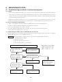
4.16 Operation permission/prohibition control
The air conditioner operation is controlled by releasing the jumper wire (J3) on the indoor control board and inputting the external signal
into the CnT.
(1) The operation mode is switched over between Permission and Prohibition by releasing the jumper wire (J3)
on the indoor control board.
When the jumper wire (J3) is short circuited
When the jumper wire (J3) is released
Normal operation is enable (when shipping)
Permission / Prohibition mode
When CnT input is set to ON, the operation starts and
When Cnt input is set to ON, the operation mode is
if the input is set to OFF, the operation stops.
changed to permission and if input is set to OFF the
For the CnT and remote control inputs, the input which
operation is prohibited.
is activated later has priority and can start and stop the
operation.
(2) When the CnT input is set to ON (Operation permission)
(a) The air conditioner can be operated or stopped by the signal from the remote control signal line.
(When the "CENTER" mode is set, the operation can be controlled only by the center input.
(b) When the CnT input is changed from OFF to ON, the air conditioner operation mode is changed depending on the status of
the jumper wire (J1) on the indoor control board.
When the jumper wire (J1) is short circuited
When the jumper wire (J1) is released
The signal (a) above starts the air conditioner.
When the CnT input is set to ON, the air conditioner
(Shipping status)
starts operation. After that, the operation of the air
conditioner depends on (a) above. (Local status)
(3) When the CnT input is set to OFF (Prohibition)
(a) The air conditioner cannot be operated or stopped by the signal from the remote control signal line.
(b) The air conditioner operation is stopped when the CnT input is changed from ON to OFF.
(4) When the operation permission / prohibition mode is set to effective by the indoor function setting selected by
the remote control, the operation depends on (1) above.
4.17 Protective control function
(1) Frost prevention for indoor heat exchanger (During cooling or dehumidifying)
(a)
Operating conditions
1)
Indoor heat exchanger temperature sensor (detected with Th2) is lower than 2.5ºC.
2)
3 minutes elapsed after the start of operation.
(b) Detail of frost prevention operation
Compressor
Indoor fan
Outdoor fan
(c)
OFF
Protects the fan tap just before frost prevention control.
Depending on the stop mode
Reset condition: Indoor heat exchanger temperature sensor (Th2) is higher than 15ºC.
-
25 -
(2)
Dew condensation prevention control [Cooling (including automatic), cooling oriented dehumidifying operation]
(a)
Operating condition: When the following conditions are met after 5 minutes or more of continuous operation after
operation starts.
Prevention control
• The humidity sensor value is 68% or higher
(b) Operation contents
Reset
1) Command of the electronic expansion valve.
63
2) When such a command is continued for 30 minutes or more, air direction
68
Humidity (%)
controls will be as listed below:
UP/ DOWN air scroll
Flap swing, UP/DOWN air scroll
Executes the command to the left.
Situations besides the ones described above
Controls the level of the UP/DOWN flap.
Louver swing, LEFT/RIGHT air scroll,
Executes the command to the left.
LEFT/ RIGHT air scroll Multi-directional Air Flow
Situations besides the ones described above
(c)
Controls the front of the LEFT/RIGHT louver .
Reset condition: When the following condition is satisfied.
• The humidity sensor value is less than 63%.
(3)
Indoor fan motor protection
When the air-conditioner is operating and the indoor fan motor is turned ON, if the indoor fan motor has operated at 300 rpm or
under for more than 30 seconds, the unit enters first in the stop mode and then stops the entire system.
Timer light illuminates simultaneously and the run light flashing 6 times at each 8-second.
(4) Three-minute forced operation
When the compressor begins operating the thermal operation is not effective for 3 minutes, so operation continues as is in the
operation mode. (After 3 minutes has passed the thermal operation is effective.)
However, stopping the compressor via a stop signal or protection control has priority.
(5) Abnormality of outdoor unit
When the indoor heat exchanger temperature does not fall to 25°C or below for 40 minutes after 5 minutes have elapsed since the
compressor operation start, the abnormality stop occurs. (The timer light flashes 2 times.)
(6) Compressor overheat protection
If the discharge pipe temperature (sensed by Th6) exceeds 115°C, the compressor stops. If the temperature is 95ºC or lower after a 3minute delay, it starts again, but if this function is reactivated again within 60 minutes, it results in an abnormal stop.
(Run light : ON, Timer light : 5 time flash)
Operation possible
Abnormal stop
95
115
Discharge pipe temperature (˚C)
-
26 -
(7) High-pressure control
The outdoor heat exchanger temperature sensor detection temperature controls the compressor.
¡ When the outdoor heat exchanger
temperature is >
= (52 type: 74˚C, 71 type: 73˚C)
Compressor
ON or OFF
OFF
68
52 type: 74
71 type: 73
Outdoor heat exchanger temp. (˚C)
(8) Serial signal transmission error protection
(a)
Purpose: Prevents malfunction resulting from error on the indoor ↔ outdoor signals.
(b) Detail of operation: If the compressor is operating and a serial signal cannot be received from the indoor control with
outdoor control having serial signals continuously for 1 minute and 55 seconds, the compressor is
stopped.
After the compressor has been stopped, it will be restarted after the compressor start delay if a serial
signal can be received again from the indoor control.
(RUN light: ON, TIMER light: 6 time flash)
(9) Sensor disconnection (room temperature, indoor heat exchanger, outdoor heat exchanger, outdoor temperature, discharge pipe)
(a)
Room temperature sensor
If the temperature detected by the room temperature sensor is –20ºC or lower continuously for 15 seconds or longer while
operation is stopped, an error indication is displayed. (Run light: 2 time flash, Timer light: ON)
(b) Indoor heat exchanger temperature sensor
If the temperature detected by the indoor heat exchanger temperature sensor is –20ºC or lower continuously for 15 seconds
or longer while operation is stopped, an error indication is displayed.
(Run light : 1 time flash, Timer light : ON)
(c)
Outdoor heat exchanger temperature sensor
If the temperature detected by the outdoor heat exchanger temperature sensor is –64ºC or lower continuously for 15 seconds
or longer while operation is stopped, an error indication is displayed.
(Run light : keep flashing, Timer light : 2 time flash)
(d) Outdoor air temperature sensor
If the temperature detected by the outdoor air temperature sensor is –64ºC or lower continuously for 15 seconds or longer
while operation is stopped, an error indication is displayed. (Run light : keep flashing, Timer light : 1 time flash)
(e)
Discharge pipe temperature sensor
After the compressor has operated for 9 minutes continuously, if there is a disconnected signal for the discharge pipe temperature sensor detected -64°C for 15 seconds, the compressor stops. After a 3-minute delay, it restarts, but if an abnormality
is detected 4 times continuously, the air-conditioner is stopped fully and an error indication is displayed. (Run light : keep
flashing, Timer light : 4 time flash)
-
27 -
4.18 List of indoor unit jumper selections
Jumper
No.
Indication on
Circuit Board
With Factory Jumper
Settings (short circuited)
J1
EXTERNAL INPUT
External input switching
J2
WIRED REMOCON
Wired remote control
J3
J4
J5
J6
OPE PERMISSION
CUSTOM
BLANK
BLANK
Operation permission/prohibition
Custom cord switching
J7
J8
J9
AUTO RESTART
LO TEMP
DIRT PREVENT
Auto restart
Set Temperature Selection
J10
J11
J12
COOL ONLY
HI CEIL
PANEL
J13
50/60
Function Name
LEVEL INPUT
Disabled
No Jumper (Open)
Reference
Page
PULSE INPUT
Page 24
Enabled
Wireless Remote Control (Disabled)
Page 37
Normal operation
Normal
Enabled
Select
Page 25
Page 17
Enabled
Disabled
Disabled
Enabled
Page 16
Page 21
No function
No function
EXTERNAL INPUT
WIRED REMOCON
OPE PERMISSION
CUSTOM
AUTO RESTART
LO TEMP
DIRT PREVENT
COOL ONLY
HI CEIL
PANEL
50/60
-
28 -
5. APPLICATION DATA
SAFETY PRECAUTIONS
¡ Please read these “Safety Precautions” first then accurately execute the installation work.
¡ Though the precautionary points indicated herein are divided under two headings,
WARNING and
CAUTION , those points
which are related to the strong possibility of an installation done in error resulting in death or serious injury are listed in the
WARNING section. However, there is also a possibility of serious consequences in relationship to the points listed in the
CAUTION section as well. In either case, important safety related information is indicated, so by all means, properly observe all
that is mentioned.
¡ After completing the installation, along with confirming that no abnormalities were seen from the operation tests, please explain
operating methods as well as maintenance methods to the user (customer) of this equipment, based on the owner’s manual.
Moreover, ask the customer to keep this sheet together with the owner’s manual.
WARNING
¡ To disconnect the appliance from the mains supply this appliance must be connected to the mains by means of
a circuit breaker or a switch (use a recognized 20A) with a contact separation of at least 3mm.
¡ The appliance shall be installed in accordance with national wiring regulations.
¡ This system should be applied to places as households, residences and the like. Application to inferior environment such as engineering shop could cause equipment malfunction.
¡ Please entrust installation to either the company which sold you the equipment or to a professional contractor.
Defects from improper installations can be the cause of water leakage, electric shocks and fires.
¡ Execute the installation accurately, based on following the installation manual. Again, improper installations can
result in water leakage, electric shocks and fires.
¡ For installation, confirm that the installation site can sufficiently support heavy weight. When strength is insufficient, injury can result from a falling of the unit.
¡ For electrical work, please see that a licensed electrician executes the work while following the safety standards
related to electrical equipment, and local regulations as well as the installation instructions, and that only exclusive use circuits are used.
Insufficient power source circuit capacity and defective installment execution can be the cause of electric shocks
and fires.
¡ Accurately connect wiring using the proper cable, and insure that the external force of the cable is not conducted
to the terminal connection part, through properly securing it. Improper connection or securing can result in heat
generation or fire.
¡ Take care that wiring does not rise upward, and accurately install the lid/service panel.It’s improper installation
can also result in heat generation or fire.
¡ When setting up or moving the location of the air conditioner, do not mix air etc. or anything other than the
designated refrigerant (R22) within the refrigeration cycle.
Rupture and injury caused by abnormal high pressure can result from such mixing.
¡ Always use accessory parts and authorized parts for installation construction. Using parts not authorized by this
company can result in water leakage, electric shock, fire and refrigerant leakage.
¡ Ventilate the work area when refrigerant leaks during the operation.
Coming in contact with fire, refrigerant could generate toxic gas.
¡ Confirm after the foundation construction work that refrigerant does not leak.
If coming in contact with fire of a fan heater, a stove or movable cooking stove, etc., refrigerant leaking in the
room could generate toxic gas.
CAUTION
¡ Execute proper grounding. Do not connect the ground wire to a gas pipe, water pipe, lightning rod or a telephone
ground wire.
Improper placement of ground wires can result in electric shock.
¡ The installation of an earth leakage breaker is necessary depending on the established location of the unit.
Not installing an earth leakage breaker may result in electric shock.
¡ Do not install the unit where there is a concern about leakage of combustible gas.
The rare event of leaked gas collecting around the unit could result in an outbreak of fire.
¡ For the drain pipe, follow the installation manual to insure that it allows proper drainage and thermally insulate it
to prevent condensation. Inadequate plumbing can result in water leakage and water damage to interior items.
-
29 -
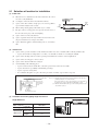
5.1 Selection of location for installation
(1)
Indoor unit
(a)
Where there is no obstructions to the air flow and where the cooled
air can be evenly distributed.
(b)
A solid place where the unit or the wall will not vibrate.
(c)
A place where there will be enough space for servicing. (Where
6.5 cm
Right
side
10 cm
Left
side
space mentioned right can be secured)
5 cm
(d)
Where wiring and the piping work will be easy to conduct.
(e)
The place where receiving part is not exposed to the direct rays of
1.5 cm
the sun or the strong rays of the street lighting.
(f)
A place where it can be easily drained.
(g)
A place separated at least 1m away from the television or the radio.
(To prevent interference to images and sound.)
(h)
A place that home appliance and househdd goods, etc. aren’t below
unit.
(2)
Outdoor unit
(a)
A place where good air circulation can be obtained and where rain, snow or sunshine will not directly strike the unit.
• A place where intake air temperature is over 46°C , it is desirable to install a roof avoiding the sunlight.
(b)
A place where discharged hot air or unit’s operating sound will not be a nuisance to the neighborhood.
(c)
A place where servicing space can be secured.
(d)
A place where vibration will not be enlarged.
(e)
Avoid installing in the following places.
• A place near the bedroom and the like, so that the operation noise will cause no trouble.
• A place where there is possibility of flammable gas leakage.
• A place exposed to strong wind.
Air inlet
100
• In a salt-laden atmosphere or a place where the generation of oil mist, vapor or fume is expected.
Notes (1) Blowing out port and suction port on the back side of the unit can be
installed at a distance of 10cm from walls.
In case the barrier is 1.2m or above in height, or is overhead, the
sufficient space between the unit and wall shall be secured.
(2) When the unit is installed, the space of the following dimension and
above shall be secured.
(
No obstacles
(Service space
for electrical
parts)
300
Air inlet
Unit : mm
Air
Outlet
)
No obstacles
(An enough open space)
(3)
Limitations for one way piping length and vertical
height difference.
Model
Item
One way piping length (R)
Outdoor
Vertical height unit is lower
difference (h) Outdoor unit
is higher
All models
h
r
25 m
15 m
15 m
-
30 -
5.2 Installation of indoor unit
(1) Installation of installation board
(a)
Fixing of installation board
Look for the inside wall structures (Intersediate support or
pillar and firaly install the unit after level surface has been
checked.)
610
450
INSTALLATION SPACE (INDOOR UNIT)
(FRONT VIEW)
Unit: mm
Mating mark for level surface
Adjustment of the installation board in the horizontal
direction is to be conducted with four screws in a
temporary tightened state.
Standard hole
Fixing on concrete wall
Use of nut anchor
Use of bolt anchor
Adjust so that board will be level by turning the board
with the standard hole as the center.
Nut
(M6)
Bolt
(M6 × 12)
Mounting
board
Max. 10
Mounting
board
(2) Drilling of holes and fixture sleeve (Option parts)
When drilling the wall that contains a metal lath, wire lath or metal plate, be sure to use pipe hole sleeve sold separately.
(a)
Drill a hole with ø65
(b) Adjusting sleeve length
whole core drill
Cut off the sleeve
collar in case of
drawing piping out
to rear.
Indoor side
Cut off the sleeve
collar that can be
seen from beneath
the unit.
Outdoor side
Wall thickness
+ 1.5 cm
Note (1) Drill a hole with incline of 5 degree from
indoor side to outdoor side.
(c)
Install the sleeve
(Inserting sleeve)
(*Sleeve + *Inclined + *Sealing plate)
Turn to
tighten
View of sleeve when installed
Inclined
flange
Sealing
Sleeve
plate
Paste
Indoor side
Outdoor side
-
31 -
Indoor side
Outdoor side
(3)
Preparation of indoor unit
(a)
Mounting of connecting wires
1) Open the air inlet panel.
2) Remove the lid.
3) Remove the wiring clamp.
4) Connect the connecting wire securely to the terminal block.
Use cables for interconnection wiring to avoid loosening of the
wires.
CENELEC code for cables. Required field cables.
H05RNR4G1.5 (Example)
H Harmonized cable type
05 300/500 volts
R Natural-and/or synth, rubber wire insulation
N Polychloroprene rubber conductors insulation
R Standed core
4 Number of conductors
G One conductor of the cable is the earth conductor (yellow/
green)
1.5 Section of copper wire (mm2)
Terminal block
Wiring Clamp
Lid
1 Connect the connection wire securely to the terminal block. If the wire is not affixed completely, contact will be poor,
and it is dangerous as the terminal block may heat up and catch fire.
2 Take care not to confuse the terminal numbers for indoor and outdoor connections.
3 Affix the connection wire using the wiring clamp.
5) Fix the connecting wire by wiring clamp.
6) Attach the lid.
7) Close the air inlet panel.
(b) Installing the support of piping
[Shaping the piping]
[Taping of the exterior]
Piping
Drain hose
¡ Hold the bottom of the piping and fix direction before
stretching it and shaping it.
¡ Tape only the portion that goes through the wall.
Always tape the crossover wiring with the piping.
[When the hose is extended to left and taken out from the rear center]
[Top View]
Left-hand-sided-piping
Piping in the left rear direction
Right-hand-sided-piping
Piping in the right rear direction
Piping in the right direction
Piping in the left direction
Piping is possible in the rear,
left, left rear, left downward,
right or downward direction.
Right
Rear
Downward Left rear
Left
Left downward
-
32 -
[Drain hose changing procedures]
1. Remove the drain hose. 2. Remove the drain cap.
¡Remove the drain hose, ¡Remove it with hand or
making it rotate.
pliers.
3. Insert the drain cap.
4. Connect the drain hose.
¡Insert the drain cap which was removed at ¡I n s e r t t h e d r a i n h o s e
procedure “2” securely using a hexagonal
securely, makingit rotate.
wrench, etc.
Note: Be careful that if it is
Note: Be careful that if it is not inserted
not inserted securely, water
securely, water leakage may occur.
leakage may occur.
Gutter
Since this air conditioner has been designed to collect dew drops
on the rear surface to the drain pan, do not attach the power
cord above the gutter.
Pipe accommodation section
Drainage
¡ Arrange the drain hose in a downward angle.
¡ Avoid the following drain piping.
Odor from
the gutter
Higher than specified
The drain hose
tip is in water.
Weavy
The gap to the ground
is 5 cm or less.
The drain hose tip is in
the gutter.
¡ Pour water to the drain pan located under the heat exchanger, and ensure that the water is discharged outdoor.
¡ When the extended drain hose is indoor, always use a shield pipe (to be arranged by the user) and ensure it is thermally
insulated.
Shield pipe
Drain hose
(c)
When it is exposed indoor.
Extended drain hose
Fixing of indoor unit
Installation Steps
1 Pass the pipe through the hole
in the wall, and hook the upper
part of the indoor unit to the
installation board.
2 Gently push the lower part to
secure the unit.
¡ How to remove the indoor unit from the installation board
1 Push up at the marked portion of the indoor unit base
lower latch, and slightly pull it toward you.
(both right and left hand sides)
(The indoor unit base lower latch can be removed from
the installation board)
2 Push up the indoor unit upward. So the indoor unit will
be removed from the installation board.
-
33 -
5.3 Installation of outdoor unit
(1)
Installation of outdoor unit
(a)
Make sure that the unit is stable in installation. Fix the unit to stable base.
(b)
When installing the unit at a higher place or where it could be toppled by strong winds, secure the unit firmly with foundation
bolts, wire, etc.
(c)
Perform wiring, making wire terminal numbers conform to terminal numbers of indoor unit terminal block.
(d)
Connect using ground screw located near
mark.
Power supply code
CENELEC code for cables requiring field cables
H05RNR3G2.5
5.4 Refrigerant piping
(1) Preparation
Keep the openings of the pipes covered with tapes etc. to prevent dust, sand, etc. from entering them.
Outdoor unit side
Indoor unit side
Remove
Remove
¡ Remove the flared nuts.
(on both liquid and gas sides)
(2)
Press
Press
(Do not
turn)
Dimension A
Liquid side
(φ6.35): 9.0 mm
Gas side
(φ15.88): 19.4 mm
¡ Remove the flared nuts.
(on both liquid and gas sides)
¡ Install the removed flared nuts to the pipes to be connected,
then flare the pipes.
Connection of refrigerant piping
Outdoor unit side
Indoor unit side
¡ Connect firmly gas and liquid side
pipings by Torque wrench.
¡ Connect firmly gas and liquid side
pipings by Torque wrench.
Spanner
(for fixing
the piping)
Torque
wrench
¡ Specified torquing value:
¡ Specified torquing value:
Liquid side (ø6.35) : 14.0~18.0N·m (1.4~1.8kgf·m)
Liquid side (ø6.35) : 14.0~18.0N·m (1.4~1.8kgf·m)
Gas side (ø15.88) : 68.0~82.0N·m (6.8~8.2kgf·m)
Gas side (ø15.88) : 68.0~82.0N·m (6.8~8.2kgf·m)
¡ Always use a Torque wrench and back up spanner to tighten ¡ Use one more spanner to fix the valve.
the flare nut.
-
34 -
(3) Air purge
(a)
Tighten all flare nuts in the pipings both indoor and outside will so as not to cause leak.
(b)
Connect service valve, charge hose, manifold valve and vacuum pump as is illustrated below.
(c)
Open manifold valve handle Lo to its full width, and perform vacuum or evacuation.
Continue the vacuum or evacuation operation for 15 minutes or more and check to see that the vacuum gauge reads – 0.1 MPa
(– 76 cmHg).
(d)
After completing vacuum operation, close the Lo handle fully and stop operation of the vacuum pump, then check to see that
the vacuum gauge needle does not return.
(e)
Fully open service valve (Both gas and liquid sides) with hexagon headed wrench.
(f)
Detach tne charge hoses, from the service port.
(g)
Check for possible leakage of gas in the connection parts of both indoor and outdoor.
Compound
pressure
gauge
Service Valve
(two-way valve)
–0.1MPa
(–76cmHg)
Service Valve
(three-way valve)
Service Port
Pressure
gauge
Gauge Manifold
(Designed specifically for R22)
Handle Hi.
Handle Lo
Charge hose
(Designed specifically for R22)
Vacuum pump
Charge hose
(Designed specifically for R22)
Vacuum pump adapter
(Anti-reverse flow type)
(Designed specifically for R22)
¡ Please use an anti-reverse flow type vacuum pump adapter so as to prevent vacuum pump oil from running back into the system.
Oil running back into an air-conditioning system may cause the refrigerant cycle to break down.
Additional refrigerant charge
When refrigerant piping exceeds 7m conduct additional refrigerant charge by weight after refrigerant piping completion.
Additional charge amount per meter = 25g/m
[Example]
How much amount of additional charge for 25m piping?
(25 – 7)m × 25g/m = 450g
450g for additional charge
(4) Insulation of connecting portion
(a)
Cover the connecting portion of the refrigerant piping with the pipe cover and seal them.
If neglecting to do so, moisture occurs on the piping and water will drip out.
Vinyl tape
(b)
To cover the connecting portion with
insulation materials, cut upper portion and
then seal it with insulation materials.
Finishing and fixing
1)
Tie up the piping with wrapping tape, and shape it so
that it conforms to which the pipe is attached.
2)
Fix them with clamps as right figure.
Insulation
Refrigerant piping
Electrical wiring
Covering tape
Drain hose
Tapping screw
-
35 -
Cover the exterior portion with covering tape and shape the piping so
it will match the contours of the
route that the piping to take. Also
fix the wiring and pipings to the
wall with clamps.
5.5 Test run
(1)
Conduct trial run after confirming that there is no gas leaks.
(2)
When conducting trial run set the remote control thermostat to continuous operation position. However when the power source is
cut off or when the unit’s operation switch is turned off or was turned to fan operation position, the unit will not go into operation
in order to protect the compressor.
(3)
Explain to the customer on the correct usage of the air conditioner in simple layman’s terms.
(4)
Make sure that drain flows properly.
(5)
Standard operation data
(220/240V)
Model
SRK52CF-BN
Item
Low pressure (MPa)
Cooling
Temp. difference between return air and supply air (°C)
Cooling
Running current (A)
Cooling
SRK52CF-BP
0.42 ~ 0.62
SRK71CF-BN
0.39 ~ 0.59
11 ~ 13
8.8 / 8.7
SRK71CF-BP
12 ~ 14
8.8 / –
10.6 / 10.4
10.6 / –
Note (1) The data are measured at following conditions
Ambient air temperature
Indoor side: Cooling ... 27˚C DB, 19˚C WB
Outdoor side: Cooling ... 35˚C DB, 24˚C WB
5.6 Precautions for wireless remote control installation and operation
(1)
Wireless remote control covers the following distances:
(a)
When operating facing the air conditioner:
5
m
ss
le
or
Wireless remote
control
5 m or less
or les
s or le
ss
or less
Notes (1) The remote control is correctly facing the
sensing element of the air conditioner when being
manipulated.
(2) The typical coverage is indicated (in the left
illustration). It may be more or less depending on
the installation.
(3) The coverage may be less or even nil. If the sensing
element is exposed to strong light, such as direct
sunlight, illumination, etc., or dust is deposited on
it or it is used behind a curtain, etc.
If the distances exceed the area indicated above, be sure to check
the receiver status.
Receiver
(b) When manipulating the remote control mounted on a
wall:
Make sure that it works normally (i.e., transmission/reception
signal is audible) before mounting.
Remote control
available in this area.
-
36 -
5.7 Installation of wired remote
control and super link adapter
(SC-AD-ER) (Optional parts)
(d)
(1) Modifying the indoor unit’s printed circuit
board
(a) Remove the air inlet panel (Refer to the installa
tion directions).
(b) Remove the front panel (Refer to the installation directions).
(c) Remove the control box
• Remove the screw and the latch, and open
the control lid.
Cut the jumper attached on the board.
• Remove the upper box.
Remove the screw, the latch and the band.
Screw
Band
Latch
Latch
•
Control lid
Latch
Cut the jumper (printed “WIRED
REMOCON”) attached on the board.
It is impossible to control by the wireless
remote control after cutting the jumper.
Jumper
(WIRED REMOCON)
Screw
• Remove the flap connector, the louver connector, the fan motor connector, the earth and the
sensor.
J1
J2
SW12 J3
J4
SW12
WIRED REMOCON
J1
J2
J3
J4
WIRED REMOCON
SW13
SW14
• Install the upper box.
Sensor
(e)
Fan motor connector
Earth
Flap/Louver connector
Screw
(Fixing the control box)
•
•
Connect the wire
• Connect the wired remote control and super
link wire.
(Please refer to the installation manual of attachment in wired remote control for details)
Band
Remove the screw fixing the control box.
Remove the control box from the base .
It is possible to remove the control box from
the base by leaning the control box slightly
to right-hand side and pulling it toward you.
Each wire can be connected the left or right
terminal block.
1
(f) Install the control box.
Be careful not to bite the wire.
(g) Install the front panel.
(h) Install the air inlet panel.
2
Notes (1) One remote control cannot control two or
more indoor units.
(2) To connect the super link, the optional SCAD-ER (super link adapter) is required.
-
37 -
(2) Installation of wired remote control (Optional
parts)
(a) Selection of installation location
Avoid the following locations
1) Direct sunlight.
2) Close to heating device.
3) Highly humid or water splashing area.
4) Uneven surface.
(b) Installation procedure
1) Exposed fiting
a) Open the remote control case.
2) Recessed fitting
a) The Electrical box and remote control (shield
wire must be use in case of extension) are
first embedded.
Remote
control cord
Electrical box
Not included
Upper
Lower case
• Put a screw driver (flat-head) into the concavity made on the upper part of a remote
control unit and twist it lightly to open the
casing.
b) The cord of a remote control unit can only
be pulled out in the upward direction.
Lower
Cable outlet
Upper
Cut off with a knife or the like thin walled parts
intended for screw holes, and then fix it with
screws.
Thin walled part
Upper
Lower
Lower case
Cable outlet
b) Remove the upper case to the remote control.
c) Attach the lower case to the Electricl box
with two M4 screws. (Head diameter must
be 8 mm). Choose either of the following
two positions in fixing it with screws.
d) Connect the remote cord to the remote
control.
Lower
• Cut off with nippers or a knife a thin walled
part made on the upper end of the rmote
control unit’s bottom casing, and then remove burrs with a file or the like.
c) Fix the remote control unit’s bottom casing
onto a wall with two wood screws supplied
as accessories.
Upper
Refer to [Exposed Fitting].
e) Installation work is completed by replacing the top casing onto the bottom casing
as before.
f) Set the function switch according to the
type of the indoor unit.
Lower case
Lower
d) Connect the remote control to the terminal
block. Connect the terminals of the remote
control to the indoor unit with the same numbers. Because the terminal block has polarity, the device becomes inoperative if there
are wrong connections.
Refer to [Function setting].
Terminals: xRed wire, YWhite wire, ZBlack wire
Upper
Two M4 screws
(Head diameter must be 8mm)
(not included)
Upper case
Board
Red White Black
X Y Z
▼
Lower
Precation in Extending the Remote control cord
Maximum total extension 600m.
The cord should be a shielded wire.
● For all types : 0.3mm2 × 3 cores
Note (1) Use cables up to 0.5mm2 (maximum) for those laid
inside the remote control unit casing and connect to a
different size cable at a vicinity point outside the remote
control unit, if necessary.
Wiring
• Use a cord of 0.3mm2 (recommended) 0.5mm2 (maximum) for a remote control
unit cord. Remove a sheathe of the remote
control unit cord for the section laid within
the remote control unit casing.
The length of each wire that should be left
after a sheath is removed is as follows:
Within 100-200m…………
Within 300m…………
Within 400m…………
Within 600m…………
Length of the
section where a
sheath is removed
0.5 mm2
0.75 mm2
1.25 mm2
2.0 mm2
× 3 cores
× 3 cores
× 3 cores
× 3 cores
● The shielded wire should be grounded at one side only.
Earth
Black: 195mm, White: 205mm, Red: 215mm
e) Replace the top casing as before.
f) Use a cord clamp to attach the remote control cord to the wall.
g) Set the functions according to the types of
indoor unit. See Section “Function Setting’’.
-
Indoor unit
Remote control cord
(Shielded wire)
(This side is not grounded)
Remote control
switch
38 -
(3) Setting functions using the wired remote control
(a)
The default settings of this unit's functions are as follows: If you want to charge a setting, follow the procedure found in the
installation manual and set to your desired setting.
For the method of setting, please refer to the installation manual of a remote control unit.
1 Remote control unit functions (
Function
number A
Function description B
FUNCTION
Setting C
2 Indoor unit functions (I/U FUNCTION
)
Function
number A
Default
setting
Function description B
Setting C
INVALID
(01)
GRILLE
(
Grille lift
SET panel setting
)
STANDARD (Mild mode)
(01)
50Hz AREA ONLY
Hi CEILING SET
Hi CEILING 1 (Powerful mode)
60Hz AREA ONLY
02
03
04
05
06
07
08
(09)
10
INVALID
1000H→STOP
04
INVALID
13
EXTERNAL INPUT SET
OPERATION PERMISSION
PROHIBITED
NORMAL OPERATION
06
NORMAL OPERATION
(07)
ROOM TEMP OFFSET
(Heating room temperature offset)
(08)
Heating
FAN CONTROL fan control
VALID
INVALID
VALID
LOUVER S/W
INVALID
VALID
TIMER S/W
INVALID
(
)
SENSOR ON (Valid)
VALID
VENTI SET
*
NO DISP CHANGE
(
)
(09)
FREEZE PREVENT TEMP
(10)
FREEZE PREVENT CONTROL
3 FAN SPEED
2 FAN SPEED
HEAT PUMP
MODEL TYPE
COOLING ONLY
EXTERNAL CONTROL SET
16
ERROR DISP SET
(18)
(
°C/°F SET
INDIVIDUAL OPERATION
SAME OPERATION FOR ALL UNITS
ERROR DISP
NO ERROR DISP
)
TEMP SHIFT +3˚C
)
LOW FAN
STOP→LOW FAN (Intermittent operation)
*
TEMP Lo
FAN CONTROL OFF
Notes(1) Setting marked with [嘷] are the default setting.
(2) Setting marked with [*] are those that are set automatically
according to an indoor unit or an outdoor unit connected.
Please check default settings with the indoor unit's installation
manual.
(3) The SRK model cannot set the items described in ( ) in the
function number A.
DISP CHANGE
Indoor unit
I/U FAN SPEED fan speed setting
VALID
FAN CONTROL ON
VENTI LINK SET
TEMP RANGE SET
PULSE INPUT
TEMP Hi
INVALID
POWER FAILURE
COMPENSATION SET
15
17
(
SENSOR OFF (Invalid)
Remote control
SENSOR S/W
sensor setting
Louver
POSITION
control setting
)
05
1 FAN SPEED
14
(
LEVEL INPUT
INVALID
FANSPEED S/W
*
Louver control FIX (1 OF 4) (4 positiion stop)
POSITION setting
IN MOTION (Free stop)
VALID
ON/OFF ON/OFF S/W
NO VENTI LINK
12
AFTER 600H
AFTER 1000H
NO VENTI
(11)
FILTER SIGN SET
VALID
VALID
MODE S/W
*
AFTER 180H
(03)
AUTO RUN OFF
TEMP S/W
Default
setting
NO DISPLAY
AUTO RUN ON
AUTO RUN SET
)
FIX (1 OF 4) (4 position stop)
IN MOTION (Free stop)
°C
°F
Notes(1) Setting marked with [嘷] are the default setting.
(2) Setting marked with [*] are those that are set automatically
according to an indoor unit or an outdoor unit connected.
Please check default settings with the indoor unit's installation
manual.
POSITION” is changed, please also
(3) When Item 17 : “
change Item 04 “
POSITION” setting found in
“Indoor unit functions”.
(4) The SRK model cannot set the items described in ( ) in the
function number A.
-
39 -
(b)
Function setting method
1) Stop the air conditioner
2) Press the SET and MODE buttons simultaneously
for 3 seconds or longer.
The screen display will be switched as follows:
“
SELECT ITEM”
“
AUTO RUN SET
SET"
“FUNCTION SET
”
FUNCTION SET
3) Press the SET button.
The unit will enter the function setting mode. The
screen display will charge to “
FUNCTION
”.
4) Check which category your desired setting belongs to, “
FUNCTION
5) Press either
FUNCTION
(Remote control unit function)” or “I/U
" (Indoor unit function).
or
Select either “
button.
FUNCTION
” or “I/U FUNCTION
FUNCTION
”.
I/U FUNCTION
6) Press the SET button.
When “
FUNCTION
” is selected.
1 “DATA LOADING” (blinking)
“
FUNCTION”
SET” (Function number: A, Function description: B)
“01 GRILLE
The screen display will be switched like this.
2 Press either
or
button.
“Function number: A, Function description: B “from the list of remote control unit functions will be displayed one by
one. Select a desired function.
3 Press the SET button.
The screen display will be switched as follows:
“
SETTING”
4 Press either
or
“Setting: C” (ex. “AUTO RUN ON”)
button.
A list of “Settings: C” will be displayed one by one. Select your desired setting.
5 Press the SET button.
The selected setting is displayed
* When “
AUTO RUN SET ” is selected.
for 2 seconds, then followed by
“SET COMPLETE” and the
function setting process is completed.
AUTO RUN SET
Then the screen display will be
swiched to “Function number:
A, Function description: B,” so
AUTO RUN ON
if you want to continue to set another function, repeat the steps as
explained above.
AUTO RUN ON
AUTO RUN OFF
To finish the function setting pro-
SET COMPLETE
cess, please proceed to Step (c).
-
40 -
When “I/U FUNCTION
” is selected.
1 The screen display will be switched as follows:
“
I/U SELECT”
“
SET”
“I/U No.00” (blinking)
I/U No.00
2 Press either
or
button.
Select the indoor unit number that you want to change settings. If only one indoor unit is connected, the indoor unit
number will not charge, so please proceed to Step 3.
If “ALL I/U
” is selected while indoor group control is in effect, you can set all units to the same settings.
3 Press the SET button.
Indoor unit number indication will change from blinking to lit continuously, The screen display will be switched as
follows:
"DATA LOADING" (blinking for about 2 to 23 seconds)
“
FUNCTION”
“05 EXTERNAL INPUT SET”
(Function number: A, Function description: B)
* When “
EXTERNAL INPUT SET” is selected.
Function number: A
EXTERNAL INPUT SET
4 Press either
or
Function description: B
button.
“Function number: A, Function description: B” from the list of indoor unit functions will be displayed one by one.
Select a desired function.
5 Press the SET button.
The screen display will be switched as follows: “
LEVEL INPUT
6 Press either
or
SETTING”
“Setting: C” (ex. “LEVEL INPUT”)
button.
A list “Setting: C” will be displayed one by one. Select your desired setting.
7 Press the SET button.
The selected setting is displayed for 2 seconds, then followed by “SET COMPLETE” and the function setting process is
completed.
Then the screen display will be switched to “Function number: A, Function description: B” so if you want to continue to set
another function, repeat the step as explained above. To finish the function setting process, please proceed to Step 8.
8 Press AIR CON No. button.
The screen display will go back to the indoor unit selection screen (ex. “ I/U No.00”).
(c)
Press the ON/OFF button.
This ends a function setting process. Even if a function setting process is not completed, this ends the process.
Please note that any setting that is not completed will become void.
¡ Pressing the RESET button during a function setting process will allow you to go back the previous
step. Please note that any setting that is not completed will become void.
¡ Method of checking the current setting
While following the above mentioned step, the setting that appears when the SET button is pressed for each “Function
number: A, Function description: B” is the current setting “Stting: C”. (When "ALL I/U
the indoor unit with the lowest number is displayed)
¡ Settings are stored in the controller and not lost even a power outage occurs.
-
41 -
" is selected, the setting of
(d) Changing the remote control’s temperature setting range
1) The temperature setting range of the remote control can be changed.
Through remote control button operations, the upper limit and lower limit set temperature values can be changed individually.
During heating operation, the changed upper limit value becomes valid and at times other than during heating operation,
(during cooling, dehumidification, auto and fan operation), the changed lower limit value becomes valid.
Range of Possible Changes
Upper Limit Value: 22~30ºC (valid during heating) Lower Limit Value: 18 ~ 26ºC (valid at times other than during
heating)
2) Operation
a) With the remote control in the stopped state, press the SET and MODE buttons simultaneously for 3 seconds or
longer. The display will changed from “
b) Press the
SELECT ITEM”
“
SET”
button once. The display will change to TEMP RANGE
“FUNCTION SET
”
.
c) Press the SET button to enter the temperature range setting mode.
d) Using the
or
button, select “Hi LIMIT SET
” or “Lo LIMIT SET
,” the press the SET button.
e) If “Hi LIMIT SET” is selected,
1 The display changes from “
2 Using the “
SET UP”
“Hi LIMIT 22ºC
” (flashing).
” button, select the upper limit value. Display example: “Hi LIMIT 22ºC
” (flashing)
3 Press the SET button to fix the setting. Display example: “Hi LIMIT 22ºC” (lighted up)
f) If “Lo LIMIT SET” is selected,
1 The display changes from “
2 Using the “
SET UP”
“Lo LIMIT 26ºC
” (flashing).
” button, select the upper limit value. Display example: “Lo LIMIT 26ºC
” (flashing)
3 Press the SET button to fix the setting. Display example: “Lo LIMIT 26ºC” (lighted up)
g) Press the ON/OFF button to end the setting procedure.
(The procedure also ends if the ON/OFF button is pressed during the setting operation. However, settings which have
not been fixed become invalid, so exercise caution.)
• If the RESET button is pressed during a setting operation, the display returns to the previously displayed setting screen.
However, settings which have not been fixed become invalid, so exercise caution.
* If “NO DISP CHANGE” is selected in No. 12, “TEMP RANGE SET” of the remote control’s functions, of the function
setting modes, the remote control’s display does not change even if the temperature range has been changed.
(Example) If the upper limit is set at 28˚C
Function No. A
12
Function Contents B
Setting Contents C
Control Contents
DISP CHANGE
The remote control’s display and sent
data upper limit changes to 28°C.
NO DISP CHANGE
The remote control’s display upper limit
remains at 30ºC and only the upper limit
of the sent data is changed to 28°C.
TEMP RANGE SET
-
42 -
(4) SUPER LINK ADAPTER (SC-AD-ER)
(a) Functions
1)
Transmits the settings from the Super link option to the indoor units.
2)
Returns the priority indoor unit data in response to a data request from the Super link option.
3)
Inspects the error status of connected indoor units and transmits the inspection codes to the Super link option.
4)
A maximum of 16 units can be controlled (if in the same operation mode).
(b) Wiring connection diagram
Connection to super link
(total length of wires: 1000 m maximum)
0.75 ~ 2.0 mm2 2-core
Blue
A
SC-AD-ER
B
Red
X
White
Y
Z
Master/Slave address
No.
1
2
3
4
Blue
Black
Network address [00] ~ [47]
X
Y
Z
Name ot the recommended signal wire
Shielding wire
Vinylcabtire round cord
Vinyl cabtire round cable
Control vinyl insulated, vinyl sheath cable
Connection to the terminal block for remote control (polar)
(total length of wires: 600 m maximum)
Master/Slave Address
SW 3-1
ON
Master
OFF
Slave
Shielding wires:
100 ~ 200 m .................
~ 300 m .................
~ 400 m .................
~ 600 m .................
0.5 mm2 × 3-core wires
0.75 mm2 × 3-core wires
1.25 mm2 × 3-core wires
2.0 mm2 × 3-core wires
● Make sure to ground one side only of the shielding wire.
1)
Set the super link network address with SW1 (10-position) and SW2 (1-position).
2)
Without a remote control (no wired remote control and no wireless remote control), set SC-AD-ER SW3-1 to ON
(Master).
Basic Connections
Outdoor unit
Internal/external Crossing
Indoor unit
X Y Z
SC-AD-ER
X Y Z
A B
X Y Z
Remote control
X Y Z
Network A B
options
-
43 -
6. MAINTENANCE DATA
6.1 Troubleshooting procedures for electrical equipment
(1)
Cautions
1 If you are disassembling and checking an air conditioner, be sure to turn off the power before beginning. When working on
indoor units, let the unit sit for about 1 minute after turning off the power before you begin work. When working on an outdoor
unit, there may be an electrical charge applied to the main circuit (electrolytic condenser), so begin work only after discharging
this electrical charge (to DC 10 V or lower).
2 When taking out printed circuit boards, be sure to do so without exerting force on the circuit boards or package components.
3 When disconnecting and connecting connectors, take hold of the connector housing and do not pull on the lead wires.
(2)
Items to check before troubleshooting
1 Have you thoroughly investigated the details of the trouble which the customer is complaining about?
2 Is the air conditioner running? Is it displaying any self-diagnosis information?
3 Is a power supply with the correct voltage connected?
4 Are the control lines connecting the indoor and outdoor units wired correctly and connected securely?
5 Is the outdoor unit’s refrigerant service valve open?
(3)
Troubleshooting procedure (If the air conditioner does not run at all)
If the air conditioner does not run at all, diagnose the trouble using the following troubleshooting procedure. If the air conditioner
is running but breaks down, proceed to troubleshooting step (4).
Important
When all the following conditions are met, we say that the air conditioner will not run at all.
1 The Run light does not light up.
2 The flaps do not open.
3 The indoor unit fan motors do not run.
4 The self-diagnosis display does not function.
Troubleshooting procedure (If the air conditioner does not run at all)
Is the correct voltage
connected for the power
supply?
NO
Make sure the correct
voltage is connected, then
perform an operation check.
* If the voltage is correct, it will be
within the following voltage range.
SRK52, 71CF-BN: 198 ~ 264V
SRK52, 71CF-BP: 198 ~ 242V
YES
With the power off, do
the flaps open manually,
then close again when
the power is turned on?
NO
Is the current fuse on the
indoor unit’s board blown?
YES
NO
YES
Proceed to the indoor unit
circuit board check.
Is there a reception
sound emitted from the
unit when it is operated
by the remote control?
NO
YES
Replace the indoor unit’s
circuit board and perform an
operation check.
Proceed to the wireless remote
control troubleshooting
procedure.
-
44 -
If the package components
are not damaged, replace
the fuse and perform an
operation check again.
(4) Troubleshooting procedure (If the air conditioner runs)
Confirm the contents of the customer complaint.
NO
The cause of the trouble can
be specifically identified.
YES
Eliminate the cause of the trouble and perform an
operation check.
Check the self-diagnosis display.
See page 46.
Identify the faulty component by using the check
procedure corresponding to the content of the trouble.
Replace the faulty component, then perform an
operation check.
Note (1) Even in cases where only intermittent stop data are generated, the air conditioning system is normal. However, if the same protective operation recurs
repeatedly (3 or more times), it will lead to customer complaints. Judge the conditions in comparison with the contents of the complaints.
-
45 -
(5)
Self-diagnosis table
When this air conditioner performs an emergency stop, the reason why the emergency stop occurred is displayed by the flashing of
display lights. If the air conditioner is operated using the remote control 3 minutes or more after the emergency stop, the trouble
display stops and the air conditioner resumes operation. (1)
Indoor unit
display panel
Run
Timer
light
light
ON
1 time
flash
6 time
flash
ON
Wired
remote
control
display
Description
of trouble
E5
Error of signal
transmission
E6
Heat exchanger
sensor error
Cause
Display (flashing) condition
●
Defective power supply,
Broken signal wire,
defective in/outdoor unit
boards
When there is no signal between the indoor unit’s board and outdoor
unit’s board for 10 seconds or longer (when the power is turned on), or
when there is no signal for 1 minute 50 seconds or longer (during
operation)(the compressor is stopped).
●
Broken heat exchanger
sensor wire, poor connector
connection
When a heat exchanger sensor wire disconnection is detected while
operation is stopped. (If a temperature of –20oC or lower is detected for
3 minutes, it is judged that the wire is disconnected.) (Not displayed
during operation.)
●
Broken room temperature
sensor wire, poor connector
connection
When a room temperature sensor wire disconnection is detected while
operation is stopped. (If a temperature of –20oC or lower is detected for
15 seconds, it is judged that the wire is disconnected.) (Not displayed
during operation.)
●
Defective fan motor, poor
connector connection
When conditions for turning the indoor unit’s fan motor on exist during
air conditioner operation, an indoor unit fan motor speed of 300 rpm or
lower is measured for 30 seconds or longer. (The air conditioner stops.)
●
Gas shortage, defective
discharge pipe sensor,
closed service valve
When the value of the discharge pipe sensor exceeds the set value.
(The air conditioner stops.)
2 time
flash
ON
E7
Room
temperature
sensor error
6 time
flash
ON
E 16
Indoor fan
motor error
ON
5 time
flash
E 36
Over heat of
compressor
●
E 37
Outdoor heat
exchanger
sensor error
Broken heat exchanger
sensor wire, poor connector
connection
When a sensor wire disconnection is detected while operation is
stopped. (If a temperature of –64oC or lower is detected for 15 seconds,
it is judged that the wire is disconnected.) (Not displayed during
operation.)
Keeps 1 time
flashing flash
●
E 38
Outdoor air
temperature
sensor error
Broken outdoor air temp.
sensor wire, poor connector
connection
When an outdoor air temperature sensor wire disconnection is detected
while operation is stopped. (If a temperature of –64oC or lower is
detected for 15 seconds, it is judged that the wire is disconnected.) (Not
displayed during operation.)
Keeps 4 time
flashing flash
Discharge pipe
sensor error
●
E 39
Broken discharge pipe
sensor wire, poor connector
connection
After the compressor has operated for 9 minutes continuously, if there
is a disconnected signal for the discharge pipe temperature sensor
detected -64oC for 15 seconds.
2 time
flash
E 59
Abnormality of
outdoor unit
—
E1
Error of wired
remote control
wiring
Keeps 2 time
flashing flash
Broken compressor wire
Broken discharge pipe
sensor wire, poor connector
connection
● Compressor blockage
●
ON
—
●
●
Broken wired remote control
wire, defective indoor unit
boards
When the indoor heat exchanger temperature does not fall to 25oC or
below for 40 minutes after 5 minutes have elapsed since the compressor
operation start.
The wired remote control wire Y is open. The wired remote control
wires X and Y are reversely connected. Noise is penetrating the wired
remote control lines. The wired remote control or indoor control PCB is
faulty. (The communications circuit is faulty.)
Notes (1) The air conditioner cannot be restarted using the remote control for 3 minutes after operation stops.
(2) The wired remote control is optional parts.
-
46 -
(6) Inspection procedures corresponding to detail of trouble
[Broken sensor wire,
connector poor connection]
Sensor error
Is connector connection good?
NO
Correct connection.
YES
NO
Is sensor resistance value good?
Replace sensor.
YES
Replace PCB.
◆ Sensor temperature characteristics
(Discharge pipe temp., outdoor unit heat
exchanger temp.)
◆ Sensor temperature characteristics
(Room temp., indoor unit heat exchanger
temp., outdoor air temp.)
Temperature (˚C)
Resistance (kΩ)
Temperature (˚C)
Resistance (kΩ)
0
164
70
8.7
127
75
7.3
99
80
6.2
15
78
85
5.3
20
62
90
4.5
25
50
95
3.9
30
40
100
3.3
35
32
105
2.9
40
26
110
2.5
45
21
115
2.2
50
17
120
1.9
55
14
125
1.6
60
12
130
1.4
65
10
135
1.3
25
Resistance (kΩ)
5
10
30
(Broken wire)
20
15
10
5
(Shortcircuit)
–10
0
20
30
40
50
60
70
Temperature (˚C)
[Defective fan motor, connector
poor connection, defective PCB]
Indoor fan motor error
Is connector connection good?
10
NO
Correct connector connection
YES
* Disconnect the fan motor
connector, then investigate
the DC fan motor and indoor
unit circuit board separately.
Is the output of the indoor unit’s
printed circuit board normal?
Is DC fan motor resistance value good?
NO
YES
Replace indoor fan motor
NO
Notes (1) See pages 50 for the DC fan motor and indoor unit circuit
board check procedure.
(2) After making sure the DC fan motor and indoor unit circuit
board are normal, connect the connectors and confirm that
the fan motor is turning.
(If power is turned on while one or the other is broken down,
it could cause the other to break down also.)
YES
Replace indoor PCB
Normal
-
47 -
[Gas shortage, defective discharge
pipe sensor]
Over heat of compressor
Is discharge pipe sensor
resistance value good?
NO
(page 47)
Connector connection check, resistance
value check, replacement of discharge pipe
sensor
YES
Is sufficient quantity of refrigerant
circulated?
NO
Does trouble persist after
charging gas?
NO
Check if there are any
places where gas is leaking.
YES
YES
Clogged capillary tube or
strainer, defective EEV, etc.
Defective outdoor unit PCB
[Wiring error including power cable, defective indoor/
outdoor unit PCB]
Error of signal transmission
NO
Does error persist after power
reset?
Trouble by transient cause, not unit trouble.
YES
NO
Are the lines connecting the indoor
and outdoor units connected
normally?
Correct improper wire connection on indoor/
outdoor unit.
YES
Is DC 0~Approx. 12V detected
between 2~3 terminals on
indoor unit terminal block?
NO
Defective indoor unit PCB
YES
Is DC 0~Approx. 12V detected
between2~3 terminals on
outdoor unit terminal block?
NO
Check crossover wires.
YES
Is AC 220/240V (BP type: AC
220V) applied between 1~2 on
the outdoor side terminal block?
NO
Defective indoor unit PCB. Check crossover wires.
YES
Defective outdoor unit PCB
-
48 -
[Compressor malfunction of
insufficient gas (refrigerant)]
Abnormality of outdoor unit
NO
Does compressor operation?
Is capacitor for compressor normal?
NO
Replace capacitor for compressor.
YES
Is connector for compressor connection
good?
NO
Correct connection
YES
YES
Replace compressor.
NO
Is heat exchanger sensor resistance
value good?
Replace heat exchanger sensor
YES
NO
Is refrigerant amount normal?
Does trouble persist after charging gas?
YES
NO
Check if there are any places where
gas is leaking
YES
Clogged capillary tube or strainer,
defective EEV, etc.
Insufficient gas
(7) Phenomenon observed after shortcircuit, wire breakage on sensor.
(a) Indoor unit
Phenomenon
Sensor
Operation
mode
Room temperature
sensor
Cooling
Release of continuous compressor operation command
Continuous compressor operation command is not released.
Heat exchanger
sensor
Cooling
Compressor stop.
(Abnormality of outdoor unit)
Continuous compressor operation command is not released.
(Anti-frosting)
Humidity Sensor
Cooling
1 in the table below.
1 in the table below.
Shortcircuit
Broken wire
1 Humidity sensor operation
Short Disconnected
wire
Circuit
Failure mode
1 Disconnected wire
Control input circuit reading
Air conditioning system operation
Humidity reading is 0%
Operates in the Dry region
2 Disconnected wire
Humidity reading is 0%
Operates in the Dry region
12 Disconnected wire
Humidity reading is 0%
Operates in the Dry region
1 and 2 are short
circuited
Humidity reading is 100%
Operates in the Cooling region.
Humidity sensor
element
Connector
(CnF)
Remark: Do not perform a continuity check of the humidity sensor with a tester. If DC current is applied, it
could damage the sensor.
Humidity sensor assembly
(b) Outdoor unit
Phenomenon
Sensor
Operation
mode
Heat exchanger
sensor
Cooling
High pressure control.
System can be operated normally.
Outdoor air
temperature sensor
Cooling
System can be operated normally.
System can be operated normally.
Discharge pipe
sensor
Cooling
Compressor overload protection is disabled.
(Can be operated.)
Compressor stop
Shortcircuit
-
Broken wire
49 -
Checking the indoor electrical equipment
(a) Indoor unit circuit board check procedure
1) Press the unit’s ON/OFF button for 5 seconds or longer (a beep which indicates receiving will be emitted). Then check
the following items.
1 The indoor unit’s fan motor runs.
2 The run light lights up.
2) There should be voltage [AC 220-240 V (BP type: AC 220V)] between terminals 1 and 2 on the terminal block.
With the analog tester set in the DC 30 V range, if the voltage at 2 (+) and 3 (-) is measured, the needle oscillates at
about 12V.
3) It is possible to run and stop the unit using the remote control.
If operation is as described above, the indoor unit’s board is normal.
Note (1) Check the voltage on the terminal block.
¡ Power supply : Between 1-2 [AC 220-240 V (BP type: AC 220V)]
¡ Signal : Between 2-3 (Changing between DC 0-Approx. 12V)
(b) Indoor unit fan motor check procedure
This is a diagnostic procedure for determining if the indoor unit’s fan motor or the circuit board is broken down.
1) Indoor unit printed circuit board output check
a) Turn off the power.
b) Remove the front panel, then disconnect the fan motor lead wire connector.
c) Turn on the power. If the unit operates when the ON/OFF button is pressed, if trouble is detected after the voltages in
the following figure are output for approximately 30 seconds, it means that the circuit board is normal and the fan
motor is broken down.
If the voltages in the following figure are not output at connector pins No. 1, 4 and 5, the indoor unit’s circuit
board has failed and the fan motor is normal.
(–)
GND
DC several V
(4~6 V)
BN type: DC 308~336V
BP type: DC 308V
5
4
3
2
1
6
5
4
3
2
1
Black
Indoor unit
circuit board
Red
6
White
CNU
Yellow
DC15V
Blue
(8)
FMI
2) DC Fan motor resistance check
Measuring Point
1 – 3 (Red – Black)
Resistance when Normal
4 – 3 (White – Black)
30 kΩ or higher
25 MΩ or higher
-
Notes (1) Remove the fan motor and measure it without power connected to it.
Notes (2) If the measured value is below the value when the motor is normal, it means
that the fan motor is faulty.
50 -
(9) How to make sure of remote control
(1)
Is remote
control normal?
NO
Remote control
defects
YES
Replace the display.
Again pushing
operating switch
Is the unit
operable with remote
control?
Operating the unit?
YES
Abnormality is not
found.
Normal
NO
Defective remote
control
NO
Does unit ON/OFF
button operates?
Operating the unit.
YES
Note (1) Check method of remote control
(a)
Press the reset switch of the remote control.
(b)
If all LCD are displayed after one (1) display, it is basically normal.
YES
NO
Control problem on
main unit
-
51 -
6.2 Servicing
(1)
Evacuation
The evacuation is an procedure to purge impurities......noncondensable gas, air, moisture from the refrigerant equipment by using
a vacuum pump. Since the refrigerant R22 is very insoluble in water, even a small amount of moisture left in the refrigerant
equipment will freeze, causing what is called water clogging.
¡ Evacuation procedure
(a)
Check to ensure that there is no internal pressure in the unit. If there is an internal pressure, it
should be relieved through the check joint.
(b)
Connect the service hoses of the gauge manifold to the check joint of the gas & liquid piping.
(c)
Connect a vacuum pump to the charge hose A . Repeat evacuation in the following sequence.
Liquid side
Start the vacuum pump.
Compound pressure gauge indicates – 0.1 MPa (–76 cmHg)
Gas side
Operate the vacuum pump for more than 15 minutes after – 0.1 MPa
(–76 cmHg) is indicated.
Check joint
Close low pressure valve 1 of gauge manifold.
Service hose
Gauge
manifold
Stop the vacuum pump.
Charge hose
Refrigerant
cylinder
Notes (1) Do not use the refrigerant pressure to expel air.
(2) Do not use the compressor for evacuation.
(3) Do not operate the compressor in the vacuum condition.
(2)
Vacuum
pump
Refrigerant charge
(a)
Discharge refrigerant entirely from the unit and evacuate the unit.
Note: Addition of refrigerant without evacuation is unreasonable, because it will result in low charge or overcharge.
(b)
Keep the gauge manifold and connect a refrigerant cylinder to the unit.
(c)
Record the weight of the refrigerant cylinder on the balance. This is necessary for making sure of the charged refrigerant
amount.
(d)
Purge air from the charge hose A
Firstly loose the connecting portion of the charge hose A at the gauge manihold side and open the valve 3 for a few seconds,
and then immediately retighten it after observing that gas is blow out from the loosened portion.
(e)
Open the valve 1 and 3 after discharging air from the charge hose A , then the gas refrigerant begins flowing from the
cylinder into the unit. Be sure to erect the refrigerant cylinder upright to let gas refrigerant flow into the unit.
(f)
When refrigerant has been charged into the system to some extent, refrigerant flow becomes stagnant, when that happens,
start the compressor in cooling cycle until the unit is filled with refrigerant to the specified weight.
(g)
Making sure of the refrigerant amount, close the valve 3
(h)
Disconnect the charge hose from the unit. Cover the valve ports of the refrigerant piping with caps and tighten them securely.
(i)
Check for gas leakage applying a gas leak detector along the piping line.
(j)
Start the air conditioner and make sure of its operating condition......high side and low side pressures and temperature difference
between return air and supply air.
-
52 -
WALL MOUNTED TYPE
ROOM AIR-CONDITIONER
Air-Conditioning & Refrigeration Systems Headquarters
16-5, 2-chome, Kounan, Minato-ku, Tokyo, 108-8215, Japan
Fax : (03) 6716-5926
-
2-
No.034(1.1A) RO