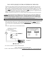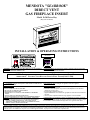
1
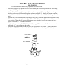
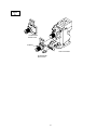
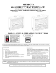
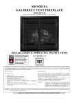
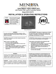
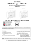
MENDOTA "SEABROOK" DIRECT VENT GAS FIREPLACE INSERT Model D-30 Flat or Bay (Bay unit not shown) INSTALLATION & OPERATING INSTRUCTIONS NO.0109 WARNING: THIS APPLIANCE TO BE USED ONLY AS AN INSERT IN SOLID FUEL BURNING FIREPLACES. AVERTISSEMENT: Cet appareil a etre employe seulment comme un inserer dans lecarburant solide brulant des cheminees. NOTE: FOR INSTALLATION AS A NATURAL VENT (B-VENT) INSERT, SEE PAGE 13. ORDER THE 4” NATURAL VENT KIT FOR SINGLE FLEX LINER (#AA-11-388). FOR YOUR SAFETY: DO NOT STORE OR USE GASOLINE OR OTHER FLAMMABLE VAPORS AND LIQUIDS IN THE VICINITY OF THIS OR ANY OTHER APPLIANCE. FOR YOUR SAFETY: WHAT TO DO IF YOU SMELL GAS: 1. OPEN WINDOWS. 2. DON'T TOUCH ELECTRICAL SWITCHES. 3. DO NOT USE ANY PHONE IN YOUR BUILDING 4. EXTINGUISH ANY OPEN FLAME 5. IMMEDIATELY CALL YOUR GAS SUPPLIER FROM A NEIGHBOR'S PHONE. 6. FOLLOW THE GAS SUPPLIERS INSTRUCTIONS. 7. IF GAS SUPPLIER IS UNAVAILABLE, CALL YOUR FIRE DEPARTMENT. WARNING: IMPROPER INSTALLATION, ADJUSTMENT, ALTERATION, SERVICE OR MAINTENANCE CAN CAUSE INJURY OR PROPERTY DAMAGE. REFER TO THIS MANUAL. FOR ASSISTANCE OR ADDITIONAL INFORMATION, CONSULT A QUALIFIED INSTALLER, SERVICE AGENCY, OR THE GAS SUPPLIER. POUR VOTRE Sécurité: Ne pas entreposer ni utiliser d’essence ni d’autre vaperures ou liquides inflammables dans le voisinage de cet appareil ou de tout autre appareil. POUR VOTRE Sécurité: Que faire si vous sentez une odeur de gaz: 1. Ne pas tenter d’allumer d’appareil 2. Ne touchez à aucun interrupteur. Ne pas vous servir des télé phones se trouvant dans le batiment ou vous vous trouvez. 3. Evacuez la pièce, le bâtiment ou la zone. 4. Appelez immédiatement votre fournisseur de gaz depuis un voisin. Suivez les instructions du fournisser. 5. Si vous ne pouvez rejoindre le fournisseur de gas, appelez le service dos incendies. AVERTISSEMENT: Une installation, un réglage, une modification, un entretien ou une maintenance incorrects peuvent entrainer des dommages matériels, des lésions corporelles ou la perte de vies humaines. Consuter le manuel des usagers fourn avec ce generateur d’air chaud. MISE EN GARDE: Installation, réglage, modification, entretien ou depannage non appropriés pourront causer des blessures ou des dommages materiels. Réferéz-vous au manuel du proprietaire fourni avac cet appariel. Pour assistance ou renseignements complémentaires, veuillez consulter un installateur expérimenté, une agence dé depannage/entreitien ou cotre compagnie gaziére. Pour utilisation avec les portes en verre certifiée l'appareil suelement. Ne pas opérer avec le verriére enlever, craquelure, brise. NOTE: FOR INSTALLATION AS A NATURAL VENT (B-VENT) INSERT, SEE REPLACEMENT MANUAL INCLUDED WITH THE 4” NATURAL VENT KIT FOR SINGLE FLEX LINER (#AA-11-388). TABLE OF CONTENTS GENERAL INFORMATION ......................................................................................................................................3 SPECIFICATIONS & CLEARANCES .......................................................................................................................4 INSTALLATION INSTRUCTIONS ...........................................................................................................................6 FLUE VENTING .........................................................................................................................................................7 RAISED HEARTH SPECIFICATIONS .....................................................................................................................15 GAS SUPPLY REQUIREMENTS ..............................................................................................................................16 GAS PRESSURE REQUIREMENTS .........................................................................................................................17 INSTALLATION CHECK OFF LIST ........................................................................................................................18 LIGHTING INSTRUCTIONS .....................................................................................................................................19 LOG INSTALLATION ...............................................................................................................................................20 WALL SWITCH, REMOTE CONTROL OR THERMOSTAT OPERATION ..........................................................25 BLOWER AND WIRING INSTALLATION OPERATION ......................................................................................26 CUSTOMER INFORMATION AND TROUBLE-SHOOTING ................................................................................28 TROUBLE SHOOTING ..............................................................................................................................................29 MAINTENANCE……………………………………………………………………………………………………30 PARTS LIST ................................................................................................................................................................31 NATURAL TO LP CONVERSION ............................................................................................................................32 INTERTEK TESTING GAS LABEL ..........................................................................................................................34 WARRANTY ...............................................................................................................................................................35 SPECIFICATIONS MODEL D-30 High Fire - Adjustable to - Low Fire BTUH. BTUH. NAT. GAS L.P. GAS 30,000 29,000 19,900 16,200 NOTE: LP CONVERSION KIT #HA-28-00194 MUST BE PURCHASED SEPARATELY. – SEE PG. 28 FOR INSTALLATION INSTRUCTIONS. MAIN ORIFICE: #35 NAT., #52 LP OVERALL EFFICIENCY ..................... EXCEEDS D.O.E. EFFICIENCY REQUIREMENTS (A.F.U.E.) FLUE VENT LINERS ........................... CO-LINEAR - 4" DIAMETER EXHAUST & 4" DIAMETER INLET or ................................................................ CO-AXIAL - 4" DIAMETER EXHAUST & 6" DIAMETER INLET TOTAL WEIGHT .................................. 175# SAFETY................................................. AGA CERTIFIED PILOT GENERATOR, MILLIVOLT SYSTEM ACTIVATED WITH SWITCH, REMOTE CONTROL OR THERMOSTAT. GAS REQUIREMENTS ........................ SUPPLY PRESSURE: GAS INLET: 3/8" N.P.T. NAT. GAS: 7" W.C. [5.0" W.C. MIN., 11" W.C. MAX.] L.P. GAS: 11" W.C. [11" W.C. MIN., 13" W.C. MAX.] ELECTRICAL REQUIREMENTS ...... 120 VOLT LISTINGS....INTERTEK TESTING SERVICES TESTED TO: ANSI Z21.11.1-1993 & CAN1-2.1 M89 "GAS-FIRED VENTED ROOM HEATERS" & CAN/CGA 2.17-M91 "GAS-FIRED APPLIANCES FOR USE AT HIGH ALTITUDES", ANSI Z21.44-1995 "GAS-DIRECT VENT WALL FURNACES" AND CGA INTERIM REQUIREMENT #41-M91 "DIRECT VENT GAS FIREPLACES" AND UL307B "MOBILE HOME, APPROVED EXCEPT RECREATIONAL VEHICLES" Gas appliances must be tested and certified by a nationally recognized testing and certification agency to American National Standards Institute - ANSI Gas Appliance Safety Standards. For more information see Pg. 34. The Mendota Gas Fireplace Insert has been tested and certified by Intertek Testing Services. 8431 Murphy Drive, Middleton, WI 53562. INSERT INCLUDES HEARTHGLO COMBUSTION SYSTEM, DUAL HOT AIR BLOWERS, 6 CERAMIC FIBER LOG MODULE & COALS, NEO-CERAM GLASS, PIEZO IGNITER AND AGA CERTIFIED SAFETY SYSTEM. OPTIONS: BLACK OR GOLD PLATED GRILL SETS, BLACK OR GOLD FILIGREE FRONTS, BLACK ARCHED DOOR KITS (ANDOVER), FEDERAL & CONTEMPORARY TRIM KITS, 3 SIZES OF SURROUNDS & 2 SIZES OF VENTING KITS. 1 CONGRATULATIONS! You are the owner of a world class heat producing gas fireplace insert. This elegant, highly efficient insert will be a constant source of comfort and fascination. It will be the focal point of beauty and interest in your home. The Mendota Gas Fireplace Insert is a true heating appliance incorporating the traditional aesthetics of fireplace fire viewing with the controllability and fuel efficiency of a home gas furnace. Of particular interest is the low fuel consumption and brilliant fire viewing afforded by the patented realistic HearthGlo wood firelike combustion system. Carefully read the following instructions prior to actual installation. Proper Mendota Gas Fireplace Insert installation and operation will give you years of safe trouble free comfort and enjoyment. If you have any questions regarding installation or operation of your Mendota Fireplace Insert please contact your local dealer. ......CAUTION..... FOR YOUR SAFETY do not install or operate your Mendota Gas Fireplace Insert without first reading and understanding this manual. Any installation or operational deviation from the following voids the Mendota Gas Fireplace Insert Warranty and may prove hazardous: Due to high temperatures, the Fireplace in which the Insert is to be installed should be located out of traffic and away from furniture and draperies. Children and adults should be alerted to the hazards of high surface temperature and should stay away to avoid burns or clothing ignition. Young children should be carefully supervised when they are in the same room as the Mendota Gas Fireplace Insert. Clothing or other flammable material should not be placed on or near the Insert. Mendota Inserts are designed for installation only in vented non-combustible fireplaces. Any fireplace in which an Insert is to be installed MUST be vented to the outside in accordance with the latest addition of Natural Fuel Gas Code. Do not connect this appliance to a chimney flue serving a separate solid fuel burning appliance. Any grill, panel or glass removed for servicing the Insert MUST be replaced prior to operating the Insert. The Mendota Gas Insert is a powerful, efficient heating unit. It has been designed as a major source of supplemental heat. It should not take the place of, or be used as, a whole house heating system. Installation and repair should be done by a qualified service person. The Insert should be inspected before use and at least annually by a professional Mendota approved service person. More frequent cleaning may be required due to excessive lint from carpeting, bedding material, etc. It is imperative that control compartments, burners and air passageways be kept clean. DO NOT use this insert if any part has been under water or exposed to moisture corrosion. Immediately call a qualified service technician to inspect the Fireplace Insert and replace any part of the control system and any gas control, which has been under water. DO NOT use this insert if burner does not light immediately. If burner does not light promptly, turn off unit and call your Mendota dealer. It is Johnson Gas Appliance Company's policy that no responsibility is assumed by the Company or by any of its employees or representatives for any damages caused by an inoperable, inadequate, or unsafe condition, which is the result, either directly or indirectly, of any improper operation or installation procedures. INSTALLER: THESE INSTRUCTIONS ARE TO REMAIN WITH HOMEOWNER. 2 GENERAL INFORMATION Your Mendota Gas Fireplace Insert has a state-of-the-art direct vent, sealed combustion system. This advanced, highly efficient system brings in outside air for combustion, has a separate exhaust vent and efficiently heats and re-circulates room air. The Mendota system maintains high air quality, maximizes efficiency and assures proper operation. SAFETY AND STRUCTURAL CONCERNS: The D-30 Fireplace Insert must be installed and serviced by a Mendota approved service person. Any adjustments to burner, pilot, logs or coal bed must be made by a Mendota approved service person. Pilot flame must be checked with volt meter. Pilot flame must register a minimum of 450 on (DC) millivolt meter. If pilot goes out, always wait five (5) minutes before relighting pilot. ALWAYS REMOVE THE GLASS WHEN LIGHTING THE PILOT. The burner must light immediately and the flame must travel promptly and smoothly around "curve" and light entire burner. The flame must not "lift" off the burner. NEVER BLOCK OFF UPPER OR LOWER GRILLS. ALWAYS USE MENDOTA GRILLS, MENDOTA VENT SYSTEMS AND MENDOTA APPROVED VENT CAPS. A non-combustible hearth protector is required and must extend a minimum of 16" in front of the glass face of the fireplace. VENTING REQUIREMENTS: Use only Mendota specified vents and vent caps when installing your fireplace insert. All vent pipe sections must be tight and leak proof. HEATING PERFORMANCE The Mendota D-30 Fireplace Insert is a true, high efficiency gas heater. With a heat output of 23,500 BTUH, the Mendota Insert will usually heat a large area of your home if situated to maximize heat circulation. NOTE: The Mendota Insert is designed as a supplemental heat source. It should not be used as a whole house heating system. Supplemental air movement considerations for maximizing heat circulation are: through-the-wall grills, floor grills, ceiling fans, or the continuous operation of central heating and cooling blowers. The most EFFICIENT and successful method for overall heat distribution is a ceiling fan. Additional information on heat is given on Pg. 28 "Customer Information". The heat output of the Insert can be reduced by up to 10,000 BTUH by slowly turning the Hi/Lo temperature knob on the front of the gas valve counterclockwise from "Hi" to "Lo". The blowers can also be turned down to reduce heat output. FIGURE 1: Main Gas Valve ELECTRICAL REQUIREMENTS A 120 volt electrical service must be supplied at the fireplace location at the time of installation. The supplied blower power cord plug must be connected to this 120 volt electrical receptacle. The blowers must be electrically grounded in accordance with local codes or in the absence of local codes, with the National Electric Code ANSI/NFPA 70-1987. The blowers are equipped with a three-prong (grounding) plug for your protection against shock hazard and should be plugged directly into a properly grounded three-prong receptacle. DO NOT CUT OR REMOVE THE GROUNDING PRONG FROM THIS PLUG! If an optional thermostat is installed, thermostat wire should be run from desired thermostat location (or "on/off" switch) to the gas control (located behind lower grill) — see optional thermostat installation section. Inlet holes are provided on left and right sides for electrical and gas connections. 3 MENDOTA GAS DIRECT VENT FIREPLACE INSERT SPECIFICATIONS & CLEARANCES MANTEL TO MANTEL OF GRILL FROM TOP 12" MIN. BRASS TRIM 20 7/16 30 1/4 FRONT VIEW 8" MAX. MANTEL DEPTH (WIDTH) 30 7/16 22 1/4 VENT ADAPTER MUST BE ORDERED SEPARATELY 3/4 7 5/8 13 1/4 15 15 16 85-03-00590 22 1/8 TOP VIEW 19 16" MIN. CLEARANCE TO SIDEWALL 16" MIN. NON-COMBUSTIBLE HEARTH EXTENSION CO-LINEAR VENT ADAPTER 4 MENDOTA GAS DIRECT VENT FIREPLACE INSERT SPECIFICATIONS & CLEARANCES MANTEL TO MANTEL OF GRILL FROM TOP 12" MIN. BRASS TRIM 20 7/16 30 1/4 FRONT VIEW 8" MAX. MANTEL DEPTH (WIDTH) 30 7/16 22 1/4 ITEM REMOVABLE FOR INSTALLATION 3/4 12 3/4 15 15 16 21 1/8 TOP VIEW 19 16" MIN. CLEARANCE TO SIDEWALL 16" MIN. NON-COMBUSTIBLE HEARTH EXTENSION CO-AXIAL VENT ADAPTER D-30 Surround Dimensions A No Brass Trim With Brass or Black Trim Inches 24 27 31 24 3/32 27 3/32 31 3/32 B mm. 610 686 788 612 688 790 Inches 36 40 44 36 3/16 40 3/16 44 3/16 FIGURE 2: D-30 Surround Dimensions 5 mm. 915 1016 1118 919 1021 1122 INSTALLATION INSTRUCTIONS CAUTION: Each installation must conform to all local, state and national codes. Refer to the national fuel gas code and local zoning and code authorities for details on installation requirements. The Mendota Inserts must be vented to the outside in accordance with the latest edition of the National Fuel Gas Code. In the absence of local codes, the installation must conform to National Fuel Gas Code ANSI Z223.1 (NFPA 54), or Canadian Code CAN1-B149 or most current edition, also known as NFPA 54. Do not connect this Insert to a chimney flue serving a separate solid fuel or gas burning appliance. 1. Remove glass doors, metal fire screens, etc. from existing fireplace. Be sure there is 12" minimum distance from top of upper grill to bottom of mantel; see Specifications [Pg.4 & 5], and a 16" minimum non-combustible hearth extension in front of the glass surface if a raised hearth is not supplied. (See pg. 15 for "Raised Hearth"). 2. Remove any additional framework or other obstructions in the existing fireplace opening and burning area. Also remove any chimney cap from top of chimney so that vent liner can be installed freely. 3. Before Insert is installed, have gas supplier or contractor run gas line to the existing fireplace. Be sure gas plumbing instructions [see Pg. 16 & 17] are carefully followed. Gas supply may enter fireplace on either side or back of fireplace, whichever is most convenient and accessible. Electrical service (120 volt) should also be supplied [See electrical requirements on Pg. 3 and blower instructions on Pg. 26]. 4. The entire chimney should be swept to remove creosote, soot and any obstructions (bird nests, etc.). 5. Open fireplace damper. If damper opening is large enough to accept 4" and 6" flue liners, permanently secure damper in "open" position NOTE: Massachusetts requires that the flue damper must be removed or permanently welded in the "open" position. 6. If damper opening is too small for the 4" & 6" flue liners, it will be necessary to remove the damper handle and the damper plate. Some damper plates are held in place by a pinned hinge, which can be released easily by tapping out the pin with a hammer and punch. Others may be held in place by a screw or bolt, or pivots may be cast into the damper housing. The latter types may be harder to get out and may require sawing or breaking out. [NOTE: if flue size is 6" (127 mm) or less, or if severe offsets occur, or a significant mortar slop is evident between the liners, try to snake liner down the chimney to the top of the damper housing before breaking out damper plate and housing.] CAUTION: If 4" & 6" flue liners cannot be installed in an extremely tight chimney DO NOT proceed with installation. 7. If damper opening is narrower than 4-1/2" to 5" (114 mm to 127 mm) and if local code authorities allow, loosen and remove mortar behind back side of damper housing in the center of the opening enough to get the gripping teeth of a pipe wrench over the flange of the damper housing (for cast iron housings). Tighten the wrench snugly, and kick down on the wrench handle to break out a half moon shaped piece of the damper housing, enough to easily fit the flex liner through it. If the opening is wide enough, the break out is not necessary. 8. INSTALL INSERT ONLY IN CHIMNEY HEIGHTS OF 12' (MINIMUM) TO 35' (MAXIMUM) -- AS MEASURED IN STEP 9 BELOW. 9. Measure the chimney height from the top of the chimney (or the existing flue liner) to a point 20" (508 mm) above the floor of the fireplace hearth. [See FIGURE pg. 8] It may be necessary to drop a rope and measure the rope itself. Be sure to allow for all offsets in existing chimney. Cut the 4" diameter flex liner (s) to this measured length. 6 FLUE VENTING 10. The D-30 Insert must be vented vertically to the outside and must use the Mendota flexible ducting system. There are two methods for venting Mendota Direct Vent Inserts: 1) Co-Axial and 2) Co-Linear CO-AXIAL VENT KIT (Typically for factory built ZC fireplaces.) NOTE: THE INSERT IS DESIGNED, TESTED AND LISTED FOR OPERATION ONLY WITH MENDOTA INSERT VENTING COMPONENTS AS LISTED IN FIGURES 3 & 4 AND DRAWING BELOW. CO-LINEAR VENT KIT (Typically for masonry fireplaces.) FIGURE 3 NOTE: Either vent kit may be used in any chimney if damper area size permits. 7 AA-11-378 CO-AXIAL VENT KIT AA-11-377 CO-LINEAR VENT KIT NOTE: THE INSERT IS DESIGNED, TESTED & LISTED FOR OPERATION ONLY WITH MENDOTA INSERT VENTING COMPONENTS AS LISTED IN FIGURES 3 & 4 AND THE DRAWING ABOVE. 11. (See FIGURE 4) The vent kits include a trimable flashing. Measure, trim and shape flashing to fit the existing flue liner. This flashing prevents water and small animals from entering area between the chimney liner and flue liner. Plan for 1” to 1-1/2” (25 mm to 38 mm) overlap on each side. Center the flashing and mark it about 3" (75 mm) larger in each dimension than the existing chimney. Trim the notch with snips and bend edges with had seaming tool, metal break or pliers. FIGURE 4: Chimney Flashing and cap 8 12. Attach a sheet metal strap loop to the flex end of the liner(s) and tie a rope to it. Two installers should proceed to the roof and drop the rope (with weight on the end to make sure it goes all the way down) and insert the liner(s) past the flexible portion, into the existing chimney [See FIGURE 5]. NOTE: Repeat this step for second liner on chimneys 9" and larger. FIGURE 5 13. One installer should then return to the fireplace opening and pull the rope to guide the liner(s) into place through the smoke shelf and the damper opening to a point 20" (508 mm) above the fireplace hearth [See FIGURE 5]. It may be necessary for the person on the roof to turn the liner slightly to avoid mortar chinks and misaligned tiles. The person below should wear leather gloves during this process to avoid being cut. CAUTION: WHEN USING FLEX ALUMINUM LINER, USE EXTREME CAUTION WHEN STRETCHING LINER AROUND OFFSETS SO AS NOT TO RUPTURE LINER. 9 14. TYPICALLY FOR FACTORY BUILT ZC FIREPLACES, REFER TO PAGE 7. Use Mendota Co-Axial Vent Kit -- # AA-11-00378 4" exhaust flex pipe extends full length of chimney - from vent boot adapter to vent cap. 6" inlet flex pipe extends from vent boot adapter to existing chimney, above damper area (approx. 4 - 5 ft.). Tightly secure flex vents with clamps provided. Seal vent cap/flashing to top of chimney with weatherproof sealer. Seal area between 6" flex pipe and chimney, at damper area, with unfaced fiberglass insulation. NOTE: In Canada, it is required that the 6” air inlet flex pipe extend up to the vent cap. 15. TYPICALLY FOR MASONRY FIREPLACES, REFER TO PAGE 7. Use Mendota Co-Linear Vent Kit -- # AA-11-00377 4" exhaust flex pipe extends full length of chimney - from vent boot adapter to vent cap. 4" inlet flex pipe extends from vent boot adapter to existing chimney, above damper area (aprox.4-5 ft.). Tightly secure 4" flex pipes using clamps provided. Seal vent cap/flashing to top of chimney with weatherproof sealer. Seal area between 4" flex pipes and existing chimney, at damper area, with unfaced fiberglass insulation. NOTE: In Canada, it is required that the 4” air inlet flex pipe extend up to the vent cap. 16. You are now ready to install the Mendota Gas Insert. A. Lift Insert vertically from carton/pallet. FIGURE 6 Glass Door Removal 17. Remove 5/16" nut and locking u-clamp from vent boot adapter (See Pg. 13). 18. You are now ready to hook up the Insert to gas supply. Be sure gas plumbing instructions [Pg. 16 & 17] and all state and local codes have been carefully followed. Be sure all items on Installation Check-Off List [Pg. 18] have been completed. NOTE: AGA APPROVED FLEX LINES ARE APPROVED FOR USE WITH MENDOTA INSERTS. 10 19. Carefully slide the Insert into place in the fireplace opening. At this time, check that Insert is level and plumb with the fireplace opening and positioned in the middle of the opening. If Insert is unsteady or needs leveling, the unit may be leveled by "shimming" body with non-combustible bricks or steel washers. FRONT SIDE VIEW CO-LINEAR CO-AXIAL FIGURE 7: Draft Diverter Installation 20. VENT BOOT ADAPTER INSTALLATION: A. Remove 2 sheet metal screws inside top of firebox at front edge. B. Remove exhaust baffle by dropping front edge downward and lifting rear edge off ledge. Set aside baffle for later re-installation. C. Reach up through firebox opening and pull vent boot adapter downward until threaded rod is visible. NOTE: Co-Linear vent boot adapter may be rotated 360ºas required. 11 21. FINAL VENT BOOT ADAPTER INSTALLATION A. Place u-clamp over threaded rod. Thread clamping nut on threaded rod and tighten firmly. B. Reinstall exhaust baffle by placing rear edge on ledge, swinging front edge upward and reinstalling two (2) sheet metal screws. CAUTION: The exhaust baffle must be reinstalled before operation. CO-LINEAR VENT ADAPTER BOOT FRONT 85-03-00509 THREADED ROD FIBERGLASS SEAL DOUGHNUT U-CLAMP 5/16" NUT SIDE VIEW CO-LINEAR CO-AXIAL 12 NATURAL VENT (B-VENT) SYSTEM INSTALLATION DRAFT HOOD MAY BE ROUND OR RECTANGULAR ACCESS PANEL SECONDARY AIR INTAKE THERMO DISK BURNER-AIRBOX ASSEMBLY MAY BE ROUND OR RECTANGULAR DRAFT HOOD FRONT FRONT 8503-00555 8503-00554 THREADED ROD SHEET METAL SCREWS (2) FIBERGLASS SEAL DOUGHNUT U-CLAMP 5/16" NUT EXHAUST BAFFLE SIDE VIEW SLIDE BACK OF EXHAUST BAFFLE INTO SLOT 22. The proper Insert surround can now be placed in position. Assemble surround by following instructions supplied with surround kit. Surround kits are available for use with each model Mendota Insert. Select the size of the surround to fill the area between the Insert and existing fireplace opening. (Fig.2, pg. 5) 13 D-30 GRILL INSTALLATION FLAT FRONT BAY FRONT FIGURE 8 ........IMPORTANT....... NOTE: INSTALLATION, SERVICING AND REPAIR MUST BE DONE BY A QUALIFIED SERVICE PERSON. THE INSERT SHOULD BE INSPECTED AT LEAST ANNUALLY BY A PROFESSIONAL SERVICE PERSON. MORE FREQUENT CLEANING MAY BE REQUIRED DUE TO EXCESSIVE LINT FROM CARPETING, BEDDING MATERIAL, ETC. IT IS IMPERATIVE THAT THE CONTROL COMPARTMENT BURNERS AND CIRCULATING AIR PASSAGEWAYS OF THE INSERT BE KEPT CLEAN. 14 RAISED HEARTH SPECIFICATIONS FIGURE 9 In most installations, a 16" non-combustible protector is required in front of the glass surface of the unit on the floor or raised hearth. This protection can be any non-combustible material such as 24 gauge sheet metal, tile, brick, concrete board, etc. If replacing a wood-burning insert with this gas insert, the existing and approved hearth protection will provide adequate floor protection. If a raised hearth extends less than 16", refer to the diagram above and the following procedure to see if additional floor protection is required. Project a line (using string or a tape measure) from the top of the lower grill to the edge of the raised hearth, continuing on to the floor. If the point of intersection with the floor is beyond 16" from the Insert, then no further floor protection is required. If the intersection is less than 16" from the Insert then additional non-combustible floor protection is required to meet the minimum 16". For installations where the fireplace is raised 16" or more (from the top of the lower grill) above the floor or if the floor is non-combustible (stone, brick, etc.), a non-combustible protector is not required. 15 GAS SUPPLY REQUIREMENTS CORRECT GAS PRESSURE AND PROPER GAS SUPPLY LINE SIZING IS IMPERATIVE TO THE SUCCESSFUL PERFORMANCE OF YOUR MENDOTA GAS FIREPLACE INSERT. BE SURE THE GAS SUPPLIER OR PLUMBER CAREFULLY CHECKS FOR CORRECT GAS PRESSURE AND GAS LINE SIZING WHEN INSTALLING THE FIREPLACE INSERT. IT IS CRITICAL TO CAREFULLY CHECK FOR GAS LEAKS WHEN HOOKING UP THE FIREPLACE INSERT -- CHECK WITH SOAP & WATER SOLUTION. BE SURE TO INSTALL FLEX GAS LINE WITH BRASS-TO-BRASS FITTINGS TO PREVENT GAS LEAKS AT CONNECTIONS. GAS SUPPLY PIPING MUST INCLUDE A DRIP LEG TO ELIMINATE THE POSSIBILITY OF CONTAMINANTS ENTERING THE GAS TRAIN. ADHERE STRICTLY TO LOCAL AND NATIONAL CODES. GAS SUPPLY LINE SIZING The Mendota Gas Insert comes equipped with a 3/8" N.P.T. [1.O cm] inlet on the main gas valve. Gas supply piping may enter the cabinet from either the left or right side. The proper gas line diameter must be selected to run from the supply regulator to the Insert. Refer to the following table for proper gas pipe diameters. SCHEDULE 40 PIPE INSIDE DIA. PIPE LENGTH [FEET] 0-10 TUBING, TYPE L OUTSIDE DIA. NAT. L.P. NAT. L.P. 1/2" [1.3 cm] 3/8" [1.0 cm] 1/2" [1.3 cm] 3/8" [1.0 cm] 10-40 1/2" [1.3 cm] 1/2" [1.3 cm] 5/8" [1.6 cm] 1/2" [1.3 cm] 40-100 1/2" [1.3 cm] 1/2" [1.3 cm] 3/4" [2.0 cm] 1/2" [1.3 cm] 100-150 3/4" [2.0 cm] 1/2" [1.3 cm] 7/8" [2.3 cm] 5/8" [1.6 cm] 150-200 3/4" [2.0 cm] 1/2" [1.3 cm] 7/8" [2.3 cm] 3/4" [2.0 cm] NOTE: Some areas allow copper tubing or galvanized pipe - check with local approval agencies and codes NEVER use plastic pipe. GAS PRESSURE CHECKING REQUIREMENTS A pressure tap for checking gas pressure is located on the main gas valve. A qualified installer should use this fitting for setting the correct gas pressure during initial installation. [See Gas Pressure Chart Pg. 17]. If supply gas pressures exceed 1/2 PSIG [3.5KPA], the appliance must be isolated from its supply with an approved manual shutoff cock. This manual shut-off cock must be closed during any supply line pressure testing. Check with your gas supplier or plumber. Figure 10 FIGURE 11: Piping Detail 16 GAS PRESSURE REQUIREMENTS A MAJOR CAUSE OF OPERATING PROBLEMS WITH GAS APPLIANCES CAN BE IMPROPER GAS PRESSURE! Such problems as changes in flame color or configuration, gas pilot or burner outages, intermittent operation, changes in heat output, excessive burner noise, etc. are nearly always the result of changes in gas pressure or improper gas pressure at the time of the installation. The most important item to check during the installation and the first thing to check when problems occur is gas pressure! Gas supplies normally enter a residence at 1/2 PSI [13" - 15" W.C.] [3. KPA]. A regulator is then placed inside the residence, which drops this pressure to 7" W.C. [1.8 KPA] [Nat. Gas]. This "inches to inches" regulator is of adequate capacity to service the gas appliances (such as dryer, furnace, etc.). If this regulator's capacity is not sufficient to add the Gas Insert, an additional "inches to inches" regulator must be installed for the Insert. EXCEPTION: Some codes allow 2 PSI [1.4KPA] supplies to enter the residence, in which case "pounds to inches" regulators are used. The following table provides information on correct gas pressure requirements. Be sure your gas supplier or plumber carefully follows this table. GAS PRESSURE REQUIREMENTS DESIRED INLET PRESSURE MINIMUM INLET PRESSURE MAXIMUM INLET PRESSURE MANIFOLD OUTLET PRESSURE AIR SHUTTER POSITION NATURAL GAS 7.0" W.C. (1.75 kPa) 5.0" W.C. (1.12 kPa) 11.0" W.C. (2.61 kPa) 3.5" W.C. (0.87 kPa) 1/8" - 1/4" OPEN (7 mm) L.P. GAS 11.0" W.C. (2.75 kPa) 11.0" W.C. (2.75 kPa) 13.0" W.C. (3.24 kPa) 10.0" W.C. (2.5 kPa) 1/2" OPEN (14 mm) TURN GAS VALVE KNOB TO "HIGH" POSITION. GAS PRESSURES MAY VARY PLUS OR MINUS 5% 1/8" Brass pressure tap fittings are located on the main gas valve. Manifold pressure must be taken at the "OUT” tap and the inlet pressure at the "IN" tap with the burner operating by a qualified installer. [See FIGURE 11 Pressure Test Port]. FIGURE 12: Pressure Test Port L.P. AND NATURAL GAS SUPPLIES The Mendota Gas Insert is available for either L.P. or Natural Gas. A Natural Gas to LPG conversion kit is supplied with the unit. 17 INSTALLATION CHECK OFF LIST The following check list must be completed prior to initial lighting of the Fireplace Insert, or manufacturer's warranty and liabilities will be voided: Venting system must be installed by a Mendota approved person according to Figure 3, Pg. 7 with clamps securely in place and all joints leak proof. Electrical supply and gas supply must be properly installed and must conform to National and Local Codes. Check that correct fuel supply is connected to appliance. Check correct gas pressure, correct size gas lines and for gas leaks. Proper clearances to combustibles must be maintained. LIGHTING CHECK OFF LIST Be sure to check these items before final operation of the Fireplace Insert All items on "Installation Check Off List" must be completed. Connect Rocker Switch, Wall Switch, Remote Control or Thermostat to main valve. Carefully follow all lighting and log installation instructions. Take system millivolt readings [See Pg. 30] Be sure pilot flame has a minimum of 450 millivolts. Make certain that burner lights immediately and flame runs promptly around "curve" in burner and lights entire burner. DO NOT proceed with operation unless burner cycles "on/off" without delays and that the flame is "stable" and not "lifting" off burner. Caution: If pilot goes out be sure to wait a minimum of 5 minutes before relighting. Always light pilot with glass and logs removed. 18 LIGHTING INSTRUCTIONS IMPORTANT: Be sure all items on "LIGHTING CHECK OFF LIST" [Pg. 17] have been completed! CAUTION: If the pilot goes out, be sure to wait a minimum of five minutes before relighting - be sure to always remove the glass before relighting the pilot. (See Pg. 10) 1. Remove Glass. - ALWAYS LIGHT PILOT WITH GLASS REMOVED! (see Fig. 6 pg. 10) 2. Make sure any gas supply shut-off cocks are open and On-Off Switch is "OFF". 3. Push in Gas Cock Dial slightly and turn clockwise to "OFF". NOTE: Dial cannot be turned from "PILOT to "OFF" unless dial is pushed in slightly. DO NOT FORCE! 4. Wait five [5] minutes to allow gas, which may have accumulated in main burner compartment to escape. If you smell gas STOP! 5. Turn Gas Cock Dial Counterclockwise to "PILOT" position [See FIGURE 13]. 6. Depress Gas Cock Dial and push in red Piezo igniter button. Once pilot ignites, continue depressing dial for about 1/2 minute. If pilot does not remain ignited, repeat operation allowing a longer period before releasing Gas Cock Dial. FIGURE 13: Gas Valve IMPORTANT: After pilot is lit, system Millivolt readings and gas pressure should be taken by qualified installer. Pilot flame must register a minimum of 450 millivolts (See pg. Error! Bookmark not defined.). Note: The Honeywell Gas Valve is equipped with a safety lockout feature. If gas flow is interrupted to the pilot light before the thermocouple is adequately heated to maintain a standing pilot, the pilot flame will go out and the Gas Valve will go into a Lockout mode. You will not be able to turn the Gas/Pilot Knob in either direction during this lockout phase. Wait 30 seconds to let the thermocouple cool down and reset the Gas Valve before attempting to light the pilot light again. Gas/Pilot knob function will resume after the 30 seconds. 7. 8. 9. After pilot is lit and before installing logs, turn Gas Dial and Rocker Switch to "ON" and "cycle" the burner on/off to make certain it ignites promptly and that the flame runs smoothly around entire burner. Note: Logs will produce a strong acrid odor on initial contact with flames (about 2 hours). With pilot operating, install logs and coals. With logs/coals in place, "cycle" the burners again to make sure of prompt ignition of burner. NOTE: Flames may not come through coals until glass is installed and logs are "hot" (approx. 10 Min.). To make final flame color adjustment wait 15-20 minutes, with glass installed. [See Pg. 29]. Reinstall glass. In daily operation, always light burner with glass in place. 10. When heat or a log fire is desired, turn Gas Dial counterclockwise to "ON". Rocker Switch, Thermostat or Remote Control must also be turned "ON". 11. Main burner should now light IMMEDIATELY and flame should not "lift" off burner. If there is any delay in ignition or if flame is "lifting off" burner, turn off burner and carefully check for proper installation of logs/coals, vent system and proper pilot flame impingement on burner and thermopile. Logs or coals must not block pilot flame or main burner flame. Vent system must be leak proof. DO NOT PROCEED WITH OPERATION UNLESS BURNER "CYCLES" ON/OFF WITHOUT DELAYS! 12. To reduce heat output, turn Hi/Lo Knob counterclockwise to desired temperature. NEVER "over fire" by increasing BTUH above nameplate specifications. NEVER turn down pilot flame below the required 450 millivolts. 13. Open windows for first 2 hours of operation and provide adequate cross ventilation in the room. NOTICE: Initial fireplace start-up will cause some NON-TOXIC "off gassing" of adhesive, gasket binders, paint and other materials. Most nuisance odors will be eliminated after the first two hours of operation; however, slight amounts may be present during the first 24 hours of operation. SHUT DOWN PROCEDURE: 1. Turn Rocker Switch, Remote Control or Thermostat to "OFF". Pilot will remain lit for return to normal service. 2. For complete shutdown turn Rocker Switch and Gas Cock Dial to "OFF". 19 LOG INSTALLATION 1. Carefully unpack 6-piece log set and bag of coals. NOTE: Logs are very fragile, handle with care. 2. Before installing glass door or logs, light pilot (See pg. 19) and cycle burner to make sure burner lights promptly and that the flame runs smoothly around burner curve and lights entire burner. 3. With pilot operating, follow LOG INTALLATION STEPS 1-9, below. 4. Place coals on front coal tray ONLY! Be sure to "fill" entire front tray with coals for true "realistic" wood log fire appearance. Coals must not block pilot or burner flame! (Additional coals may be scattered on firebox floor for realism). Placement of coals has a big effect on front burner flame appearance and "glow" of coals. More coals = less flame and more glow. Fewer coals = more flame, less "glow". 5. Cycle on main burner to insure the flame smoothly runs around the curved section of the burner and lights front burner with no delays. If there are any delays in ignition or flame movement it will be necessary to check for correct positioning of logs and coals (coals or logs must not block pilot flame or burner flame) and to check pilot flame with millivolt meter (See Pg.30). Pilot flame must register a minimum of 450 millivolts. Check that flame is "stable" and not "lifting" off burner. DO NOT proceed with operation unless entire burner lights immediately and flame is not "lifting" off burner. 6. Reinstall glass. You can now proceed with normal daily operation. In daily operation main burner should always be lit with Insert glass in place. 7. Heat can be reduced by turning Hi/Lo Knob on Gas Valve counterclockwise to desired gas input. Blowers can also be turned down to reduce heat output. NEVER "over fire" by increasing BTUH above nameplate specifications. NEVER turn down pilot flame below required 450 millivolts. NOTE: The Mendota Gas Fireplace Insert is designed to limit combustion air for maximum heating efficiency. Because of this high efficiency design the realistic "orange" flame color may take 15-30 minutes to appear. When the Fireplace Insert is first turned on the flame will be transparent or slightly "bluish". After about 15-30 minutes of operation the logs will heat up and the gas flame will become a realistic yellow-orange color. (See "Air Shutter Adjustment" page 29) LOG INSTALLATION STEP 1 LOG INSTALLATION STEP 2 LOG INSTALLATION STEP 3 21 LOG INSTALLATION STEP 4 LOG INSTALLATION STEP 5 22 LOG INSTALLATION STEP 6 LOG INSTALLATION STEP 7 23 LOG INSTALLATION STEP 8 LOG INSTALLATION STEP 9 24 WALL SWITCH, REMOTE CONTROL OR THERMOSTAT OPERATION The Insert comes with an "ON-OFF" Rocker Switch located in the lower right hand corner of the surround. An optional Wall Switch, remote control or thermostat may be purchased to substitute for the Rocker Switch. A thermostat should be placed in the same room as the fireplace, approx. 4-5 ft. off the floor. Do Not place thermostat near the fireplace. Thermostat must be 450 to 750 Millivolt rated. An on-off wall switch or remote control may be used if Insert is not used primarily as a supplementary heat source. When installed in a sleeping area, a thermostat is required. NOTE: If thermostat is located over 25 ft. from the fireplace the pilot flame may need to be increased. CAUTION: BURNER SHOULD LIGHT IMMEDIATELY AFTER TURNING WALL SWITCH OR THERMOSTAT "ON". IF BURNER DOES NOT COME ON IMMEDIATELY TURN THE THERMOSTAT/WALL SWITCH OFF AND WAIT 60 SECONDS BEFORE TURNING ON AGAIN. IF BURNER DOES NOT COME ON IMMEDIATELY AFTER SECOND TRY RECHECK COMPLETE INSTALLATION OF LOGS, PILOT, ETC. TO INSURE PROPER PILOT FLAME IMPINGEMENT ON THE THERMOPILE AND PROMPT BURNER IGNITION. NEVER TURN BURNER ON & OFF "QUICKLY" - ALWAYS WAIT 60 SECONDS! When using remote control be sure to hold in button firmly until Insert lights. DO NOT push button and release quickly before Insert lights. Insert should light IMMEDIATELY and then button can be released. If Insert does not light immediately release button, wait 60 seconds and repeat lighting procedure. Use two-wire, copper lead wire per chart and install as follows: RECOMMENDED MAXIMUM LEAD LENGTH (TWO-WIRE) WHEN USING WALL THERMOSTAT (CP-2 SYSTEM) WIRE SIZE MAX. LENGTH 14 GA. 100 FT. 16 GA. 64 FT. 18 GA. 40 FT. 20 GA. 25 FT. 22 GA. 18 FT. THERMOSTAT (STANDARD) WALL SWITCH OR REMOTE ON/OFF SWITCH THERMOCOUPLE [FIGURE 14] WALL SWITCH/ THERMOSTAT/ REMOTE WIRING DIAGRAM NOTE: Thermostat Must Be 450-750 Millivolt Rated CAUTION: THIS CONTROL IS A MILLIVOLT SYSTEM. NO ADDITIONAL POWER SUPPLY CAN OR SHOULD BE USED. 25 BLOWER OPERATION AND WIRING The D-30 Mendota Gas Inserts are equipped with hot air dual blowers. A 120 volt electrical service must be supplied for these blowers at the fireplace at the time of installation. These specially designed Blower Kits include an automatic snap switch that automatically turns the blowers "On" after heat up (12- 20 min.) and "Off" after the unit cools (approx. ½ hr.). A variable speed rheostat is also included that allows the operator to fully adjust the blower hot air output. The low profile centrifugal blowers are made of special high temperature rated ABS for constant high-speed operation at high temperatures. Blowers are equipped with long-life, maintenance-free ball bearings that ensure quiet operation and maximum airflow. The blowers are ideal for owners who wish to maximize the heating capacity and efficiency of Mendota Gas Fireplaces. The blowers greatly increase total heating capacity by forcefully moving hot air away from the fireplace and mantel area and out into the room. The blowers increase the overall efficiency of the Mendota units by up to 5%. FIGURE 15 WARNING: LABEL ALL WIRES PRIOR TO DISCONNECTION WHEN SERVICING CONTROLS. WIRING ERRORS CAN CAUSE IMPROPER AND DANGEROUS OPERATION. VERIFY OPERATION AFTER SERVICING. 26 BURNER ORIFICE FIGURE 16 BLOWER (S) REMOVAL 1. Refer to FIGURE 16. Disconnect power to fireplace and blowers. 2. Turn main gas supply valve to gas insert to OFF position. 3. Remove door assembly, logs and coals. 4. Disconnect gas supply piping/ tubing from gas valve. 5. Disconnect electrical connection at the Snapdisk thermostat by carefully pulling off wires connected to the Snapdisk thermostat. 6. Disconnect wiring connection between gas valve and ON/OFF switch or thermostat wires. 7. Remove two sheet metal screws that hold down the burner tube weldment, and remove burner. 8. Remove all sheet metal screws from Removable Burner Pan. Remove entire Burner Pan carefully and set aside. 9. Remove two (2) metal screws that secure blower assembly to unit floor. Blower(s) can then be removed through the rectangular access hole. Once blowers have been replaced or serviced, reassemble in reverse order. NOTE: Seal access plate with stove cement or 600ºF RTV sealant before assembling in place. 27 CUSTOMER INFORMATION AND TROUBLE-SHOOTING MAXIMUM ALLOWABLE SURFACE TEMPERATURE Mendota Inserts/Fireplaces comply with UL Standards for maximum surface temperatures on exposed combustible surfaces adjacent to the Insert. The Maximum allowable surface temperature is 117° F. over ambient (room) temperature. Thus, if a room is 70° – 80° the exposed combustible surfaces immediately surrounding the Insert can have a surface temperature as high as 187° F. – 200° F. (too hot to touch). OVER FIRING/UNDER FIRING OF BURNER NEVER "over fire" units by adjusting gas pressure or enlarging main orifice size to increase BTUH above nameplate specifications. Over firing can cause permanent damage to firebox and deterioration of parts and void warranty. NEVER "reduce" pilot flames below the required 450 millivolts. PILOT OUTAGE AND RE-LIGHTING If pilot goes out, be sure to wait a minimum of five minutes before re-lighting. Be sure to always remove glass before lighting pilot. CLEANING VIEWING GLASS The viewing glass should be cleaned periodically. Exterior glass may be cleaned with cleaner as desired. Interior glass - use soap and water. NEVER USE ABRASIVE CLEANERS, NEVER CLEAN GLASS WHILE OPERATING, OR WHEN GLASS IS HOT. NOTE: Additives that are put in gas (both natural and propane) to make it smell can be harmful to glass and can leave a white film deposit on the glass. This deposit can be removed with cleaners such as KEL KEM “Polish Plus” (See your dealer). In some cases (especially propane) additives can cause “crazing” or etching on the glass. Although this is not normal, it is not covered under the warranty. The solution may be to change propane suppliers. Sooting is caused by improper installation or operation. At the first sign of "sooting" (usually a thin black film on the Fireplace viewing glass) the unit must be immediately turned off and the local Mendota dealer promptly informed. Mendota products are designed and tested to operate without producing any "sooting" when installed and operated correctly. Mendota dealers will correct "sooting" problems, but Mendota and their dealers are not responsible for damage caused by excessive sooting that has not been immediately brought to their attention. AGA/ANSI APPROVAL Gas appliances must be tested and certified by a nationally recognized testing and certification laboratory to ANSI [American National Standards Institute] gas appliance safety standards. The Mendota Gas Fireplace Insert has been tested and certified by Intertek Testing Services. 8431 Murphy Drive, Middleton, Wisconsin 53562. The Mendota Gas Fireplace Inserts have met all necessary AGA/ANSI Standards and are fully certified for installation in any community. 28 TROUBLE SHOOTING MENDOTA GAS FIREPLACE INSERT SYMPTOM 1. Thin black coating [soot] forms on viewing glass. PROBABLE CAUSES A. Incorrect gas pressure B. Not enough combustion air CORRECTIVE ACTION Have gas supplier check for correct gas pressure [7" W.C. Nat. Gas; 11" W.C. LP Gas]. If sooting continues open-air shutter on burner [see "Gas Flame Adjustment" below]. If sooting still continues, call a Mendota dealer. NOTE: To clean glass - remove glass and wipe glass with cloth or paper towel. 2. Humming or whistling coming from Fireplace Insert. A. Normal operating noise. Some noise is normal. It is caused by the gas supply flowing through the gas orifice. It is expected from any gas fireplace. The noise can be reduced by turning the Hi/Lo Knob on the control. Turning down the flame will reduce the heat output of the Insert. 3. A change in flame appearance or burner operation. A. A change in gas pressure. Have your gas supplier check for correct gas 7" W.C. Nat. Gas; 11" W.C. LP Gas]. If flame still needs adjustment see "Flame Adjustment" below. Clean out carbon, spider webs, lint, etc. from shutter area. NEVER BLOCK AIR INTAKE OR OUTLET VENTS. B. Carbon dirt or lint. GAS FLAME ADJUSTMENT FIGURE 17: Air Shutter Adjustment During the initial installation, a qualified person should check the air shutter opening to make certain that the shutter is set correctly at 1/8" to 1/4" open for natural gas and full open for L.P. gas. NOTE: For altitudes above 5,000 ft., some variations may be required. Furthermore, deration of gas input may be required. Contact your gas supplier for appropriate information on derating this appliance for high altitude installations. Be sure burner and logs are properly installed (see pgs. 20-24). After burner has been properly installed and operated for 2-3 hours, small additional adjustments to the air shutter may be necessary for final flame appearance. These small shutter adjustments can be made by the following procedure: [NOTE: Very small changes in shutter settings make major changes in flame appearance.] 1. Air shutter control is located behind the lower grill. 2. If flame is too "blue," push air shutter knob in (close) in small 1/8" increments until flame turns desired realistic "orange." 3. If flame is too "orange" or is causing sooting on viewing glass, pull air shutter knob out (open) in approx. 1/8" increments until sooting stops. IF SOOTING DOES NOT STOP, TURN OFF UNIT AND CALL YOUR MENDOTA SERVICE PERSON. IMPORTANT: Try each new shutter setting approx. ½ hr. before making additional changes. NOTE: Changes in front burner flame can be made by re-arranging the coals. (See pg. 20) CAUTION: Any changes in pilot flame must be made by qualified person and checked with volt meter. 29 MAINTENANCE 1. ANNUAL MAINTENANCE OF MENDOTA UNITS IS REQUIRED. The following procedures must be performed each year by a Mendota approved service person. NOTE: Any adjustments to burner, pilot or logs must be done by a qualified Mendota service person. A. Clean all lint and dust build-up around the control. Inspect the condition of any wiring under the burner for melting or damage. B. Remove logs & coals and clean away any foreign matter (lint, carbon, etc.) on the burner and logs. Be sure the burner ports are "open". Clean the pilot and under side of the logs for any carbon deposits. NOTE: Logs should be visually checked for carbon "build-up:. If carbon deposits are visible on logs, unit should be turned off and Mendota service person contacted. FIGURE 18 C. Make sure hot air outlet grills are free from lint and other obstructions. Never block or obstruct grill openings. Check condition of gaskets, gaskets must be tight, replace if necessary. D. Check that chimney flue and outlet are open and free of blockage. E. Before re-installing glass, have qualified service person check the operation of the pilot with a millivolt meter and cycle the burner per LIGHTING INSTRUCTIONS (see Pg. 19). 2. COMBUSTION SYSTEM MILLIVOLT READING: Millivolt readings must be taken by a qualified installer at the time of installation and after any interruption in burner operation. These readings will establish proper thermopile Millivolt generation and assure trouble-free burner operation. Readings must be taken with: a.] Pilot ONLY operating. b.] Main Burner operating. A. PILOT ONLY OPERATING - Thermostat "OFF" - Minimum Millivolts 450 Using a Millivolt Meter a millivolt reading should be taken by attaching Meter leads to terminals #1 and #2 on the main gas valve. The Meter must read a minimum of 450 millivolts with the Pilot Light operating, Thermostat turned "OFF" and Main Burner "OFF". To increase or decrease millivolts, (and pilot flame) adjust pilot screw on control. (See below) B. MAIN BURNER OPERATING - Rocker Switch "ON" - Minimum Millivolts 100. Using a Millivolt Meter, a millivolt reading should be taken by attaching Meter leads to terminals #2 and #3 on the millivolt panel on the main gas valve. The Meter must read a minimum of 100 millivolts with the Gas Cock Dial turned "ON", Rocker Switch “ON” and Main Burner operating. CHECK TEST TO TEST CONNECT METER LEADS TO TERMINALS THERMOSTAT CONTACTS METER READING SHOULD BE A COMPLETE SYSTEM 2&3 CLOSED 100MV OR MORE B THERMOPILE OUTPUT 1&2 OPEN GREATER THAN 450 MV C SYSTEM RESISTANCE 1&3 CLOSED LESS THAN 80 MV D AUTO/ PILOT DROPOUT 1&2 OPEN BETWEEN 120-30 MV Figure 19: Millivolt ReadFIGURE 19: Millivolt Readings 3. THE VIEWING GLASS SHOULD BE CLEANED PERIODICALLY. Exterior glass may be cleaned with cleaner as desired. Interior glass - use KEL KEM "Polish Plus", part # 65-06-00455. WARNING: NEVER CLEAN GLASS WHEN UNIT IS HOT. DO NOT USE ABRASIVE CLEANERS. BREAKAGE AND SCRATCHES MAY RESULT. 30 REPLACEMENT PARTS LIST MENDOTA GAS FIREPLACE INSERT - MODEL D-30 PART NO. DESCRIPTION PART NO. HA-28-00040 65-06-00449 HA-28-00050 65-06-00581 HA-27-00073 HA-27-00154 2 required HA-27-00152 HA-27-00153 Flat Glass Door Assy Flat Glass Bay Door Assy Bay Glass Flat Door Gasket Bay Door Gasket On the following 2 items Bay Glass Horizontal Gasket Bay Glass Vertical Gasket 35-01-00296 35-01-00240 35-01-00239 35-01-00294 35-01-0029 65-06-00602 10-01-00046 15-02-00064 15-02-00065 05-01-00157 TimberFire Log Set Bag of Coal Glowing inswool Klinker Firebrick Kit Klinker Bay Door Brick Black Paint Rheostat Blower w/ Motor (RH) Blower w/ Motor (LH) Thermo-Disc (Snap Disc) DESCRIPTION HA-28-00193 05-02-00306 HA-28-00194 05-02-00290 HA-27-00015 HA-27-00016 Valve Assy – NG-SIT 05-02-00284 05-02-00283 05-04-00035 05-04-00036 05-07-00061 05-07-00067 Hi / Low extension knob On /Off extension knob-SIT Pilot Assy complete L.P. Pilot orifice Thermopile Thermocouple 10-10-00104 65-06-00149 On / Off switch Piezo Igniter SIT VALVE NAT. GAS L.P. Kit-SIT L.P. Regulator Main Orifice Natural Gas #35 Main Orifice LP Gas #52 WARNING Use only authorized parts and materials obtained from Johnson Gas Appliance Company when replacing defective or damaged glass. Do not cut or use glass from other suppliers. DO NOT substitute other manufacturer's materials or components. DO NOT operate unit with cracked, broken or missing glass. DO NOT FORCE STRIKE OR SLAM GLASS DOOR ASSEMBLY 31 NATURAL TO LP GAS CONVERSION HA-28-00194 This conversion must be made by a qualified service technician. 1. Turn off gas supply at the appliance service valve. Identify the Pressure Regulator on the Valve Body, see Figure 19 on Page 30. 2. Using a ¼” flat blade screwdriver, remove 3 screws that secure the NG Pressure Regulator to the gas valve body and remove NG Pressure Regulator as shown on PAGE 33. Identify the pressure regulator spring that is located in the center of the black rubber gasket. Discard both the black rubber gasket and spring. 3. Install the new LP Pressure Regulator onto the gas valve body in the same position and orientation as the NG Pressure Regulator you removed in Step 2, above. The LP Pressure Regulator can only be mounted in one position. Secure the LP Pressure Regulator in place using the 3 screws you removed in Step 2. Tighten down using a ¼” flat blade screwdriver. 4. Install main burner orifice #HA-27-00016 (#52 drill) see pg. 27 for location. Orifice is removed and installed with a ½” deep well socket and ratchet. 5. Install pilot orifice thimble #05-04-00036 (.014”) see Figure below for location. Remove and install pilot hood with 7/16” open-end wrench. (Pilot orifice thimble is located inside pilot hood base). PILOT HOOD USE 7 16" WRENCH TO LOOSEN HOOD PILOT ORIFICE Figure 20 32 Figure 21 LP PRESSURE REGULATOR SCREWS GAS VALVE BODY NG PRESSURE REGULATOR 33 "LABEL REPRESENTATION " LISTED GAS-FIRED DIRECT VENT ROOM HEATER POÊLE AU GAZ HOMOLOGUE’, A AÉRATION DIRECTE MODEL: D-30 CERTIFIED FOR CANADA HOMOLOGUÉ POUR LE CANADA Also for use in mobile (manufactured) homes after first sale of home. Convenant également pour installations dans des maisons mobiles. Tested to (Testé aux normes) ANSI Z21.11.1-1993, CAN1-2.1-M89, CAN/CGA 2.17-M91, ANSI Z21.44-1995 and CGA I.R. #41-M91. _________________________________________________ WARNING: Improper installation, adjustment, alteration, service or maintenance can cause property damage, personal injury, or loss of life. Refer to the owner's information manual provided with this appliance. Installation and service must be performed by a qualified installer, service agency or the gas supplier. Use only glass assemblies certified for use with this appliance. Do not operate with glass panel(s) removed, cracked, or broken. MISE EN GARDE: Installation, réglage, modification, entretien ou depannage non appropriés pourront causer des blessures ou des dommages materiels. Réferéz-vous au manuel du proprietaire fourni avac cet appariel. Pour assistance ou renseignements complémentaires, veuillez consulter un installateur expérimenté, une agence dé depannage/entreitien ou cotre compagnie gaziére. Pour utilisation avec les portes en verre certifiée l'appareil suelement. Ne pas opérer avec le verriére enlever, craquelure, brise. NOT FOR USE WITH SOLID FUEL (NE DOIT PASÉ UTILISÉ AVEC UN COMBUSIBLE SOLIDE) _________________________________________________ NATURAL GAS PROPANE GAS (Gaz Naturel) (Gaz de petrole liquefie (GPL)) Input Rating (Btu/hr) 0-1370 m (Entrée nominale) 30,000 29,000 Min. Input Rating (Btu/hr) 0-1370 m (Mininale Entrée nominale) 19,900 16,200 Orifice (DMS) )-1370 m (Orifice) 35 52 Maximum output (Btu/hr) (Sortie maximale) 23,300 23,100 Manifold Pressure (in w.c./kPa) (Pression au collecteur) 3.5/0.87 10.0/2.5 Manifold Pressure, low (in w.c./kPa) Pression d'entree minimale) 1.7/0.42 3.6/0.90 Minimum Inlet Pressure (in w.c./kPa) (Pression d'entrée minimale) 5.0/1.25 11.0/2.75 _______________________________________________ This appliance must be installed in accordance with local codes if any; If not, follow ANSI Z223.1 or CAN/CGA-B149. Mobile (Mfd.) home installations must adhere to Title 24 CFR, Part 3280, or CSA Z240.4. Cet appareil sera installé conformémént avec les codes locaux, le cas écheant. Si aucun code n'existe, suivez la norme ANSI Z223.1 ou la norme CAN/CGA (ACNOR)-B149. _______________________________________________ MINIMUM CLEARANCES FROM COMBUSTIBLE CONSTRUCTION Unit to sidewall 16 in. Unit top to mantle 21 in. Unite en cote 405 mm Unité en manteau de cheminée 535 mm CAUTION: Hot while in operation. Do not touch. Keep children, clothing, furniture, and flammable liquids or vapors away. ATTENTION: L'appareil est chaud lorsqu'il fonctionne. Ne pas toucher l'appareil. Survieller les enfants. Garder les vétements, les meubles, l'essence ou autres liquides a capeur inflammables loin de l'appareil. _______________________________________________ Electrical Rating (Courant nominal): 120 volts 60 Hz Less than 1 Ampere _______________________________________________ Manufactured by (Fabriqué par): JOHNSON GAS APPLIANCE CEDAR RAPIDS, IOWA DO NOT REMOVE OR COVER THIS LABEL VEILLEZ Á NE JAMAIS ENLEVER NI DISSIMULER CETTE ÉTIQUETTE WH# __________________ 34 MENDOTA WARRANTY QUALIFICATION & SERVICE REFERENCE FORM As a part of Mendota's on-going program of customer satisfaction, this Form verifies proper installation and operation. It is important as a reference for future service. It insures long life and trouble-free operation of Mendota fireplaces & stoves and qualifies the owner for Mendota's lifetime limited warranty. Owner should sign Form when completed. Optionally, please register your product at our website at: WWW.JOHNSONGAS.COM/MENDOTA-REGISTRATION.ASP HOME OWNER: _______________________________ DEALER: __________________________________________ ADDRESS: ____________________________________ ADDRESS: _________________________________________ CITY/STATE/ZIP: ______________________________ CITY/STATE/ZIP: ___________________________________ SIGNATURE: __________________________________ PHONE: ___________________________________________ MODEL #: D-30 SERIAL #: ___________________ DATE INSTALLED: __________________________________ GAS ________ NAT or _________ L.P. Mendota Fireplace Inserts are sophisticated, hi-tech gas appliances. All installation and operating instructions must be carefully followed. The DXV fireplace must be installed and serviced by a qualified Mendota approved service person. REF: MENDOTA GAS FIREPLACE INSERT APPROVED VENT PIPES AND VENT CAP INSTALLED - Per Manual and manufacturer's specifications CHECK FOR PROPER CLEARANCES TO COMBUSTIBLES - Per pipe manufacturer's specifications INSTALL PROPER SIZE GAS LINES - CHECK FOR GAS LEAKS - Per Manual CHECK FOR CORRECT GAS PRESSURE AT MANIFOLD - Per Manual a. 3.5 Inches Water Column Maximum - Nat. Gas b. 10.5 Inches Water Column Maximum - L.P. Gas TAKE COMBUSTION SYSTEM MILLIVOLT READINGS [ See Manual Pg. 26] a. Pilot only - [Minimum Millivolts 450] Reading: ______________________ b. Main burner operating - [Minimum Millivolts 155] Reading: ______________________ CYCLE BURNERS ON/OFF FOR PROMPT IGNITION - Per "LIGHTING INSTRUCTIONS" Burner must light IMMEDIATELY - Flame must travel promptly around "curve" & light burner. INSTALL LOGS AND ADJUST FLAME - Per Manual Proper pilot flame impingement on thermopile & burner - Air shutter opening: 1/8" - 1/4" Nat. Gas - 1/2" LP BRIEF OWNER ON OPERATION AND MAINTENANCE OF UNIT Light Pilot Operate Burner Explain blower "delay" operation WARRANTY REGISTRATION Your Name ______________________________________________________________________ Address _________________________________________________________________________ City ________________________________________ State ______ Zip ______________________ Dealer (Place of Purchase)___________________________________________________________ City ________________________________________ State ______ Zip ______________________ Date of Purchase _______________________ Serial Number _______________________________ Purchaser's Signature _______________________________________________________________ MENDOTA FIREPLACE INSERT, D-30 CUT OUT PAGE AND MAIL TO: JOHNSON GAS APPLIANCE CO., 520 E AVE. N.W. , CEDAR RAPIDS, IOWA 52405 OR REGISTER YOUR NEW INSERT AT : WWW.JOHNSONGAS.COM/MENDOTA-REGISTRATION.ASP 35 TAPE SHUT ------------------------------------------------------------------------------------------------------------------------------------------------------- POSTAGE NEEDED JOHNSON GAS APPLIANCE COMPANY 520 E AVENUE N.W. CEDAR RAPIDS, IA 52405 36 MENDOTA EXTENDED LIFETIME PROTECTION AND LIMITED WARRANTY MENDOTA GAS FIREPLACE INSERT MODEL: D-30 NAT. & L.P. Mendota Division of Johnson Gas Appliance Company, 520 E Avenue N.W. Cedar Rapids, Iowa 52405, extends this Extended Lifetime Protection and Limited Warranty to the original purchaser of a Mendota Gas Fireplace Insert, Serial Number, which is limited and used under normal home conditions. STANDARD WARRANTY: JOHNSON GAS APPLIANCE CO., MENDOTA DIVISION, WARRANTS THAT YOUR NEW MENDOTA GAS FIREPLACE INSERT IS FREE FROM MANUFACTURING AND MATERIAL DEFECTS FOR A PERIOD OF ONE YEAR FROM THE DATE OF INSTALLATION, SUBJECT TO THE FOLLOWING CONDITIONS AND LIMITATIONS: EXTENDED LIFETIME WARRANTY: THE HEAT EXCHANGER, THE BURNER TUBE, AND THE COMBUSTION CHAMBER OF THE MENDOTA GAS FIREPLACE INSERT ARE WARRANTED FOR THE LIFETIME OF THE ORIGINAL OWNER, SUBJECT TO PROOF OF PURCHASE AND THE FOLLOWING CONDITIONS AND LIMITATIONS: 1) This new Mendota Fireplace Insert must be installed and serviced by a competent, authorized service contractor. It must be installed and operated at all times in accordance with the installation and operating instructions furnished with the Fireplace. All adjustments to logs, coals or burner must be made by an authorized Mendota Service person. This limited warranty does not cover the cost of service calls, the cost of labor to remove or install parts covered by this limited warranty, freight or other transportation expenses, which may be incurred in connection with obtaining performances under this limited warranty. The remedy for damages as the result of any defects in this product which have been warranted herein is limited to replacement parts and does not include any incidental, indirect or consequential damages or expenses sustained in connection with the products, including damages to property, except as provided by law. 2) This warranty is non-transferable and is made to the original retail purchaser only and provided that the purchase was made through an authorized Mendota dealer. Mendota is not responsible for any damage to or malfunction of the Insert unless caused by a defect in material or workmanship from normal home use. Damage caused by abuse, improper installation or operation, installation by unqualified personnel or breach of the conditions of this limited warranty will excuse Mendota from performance of any part of the limited warranty. This warranty does not cover glass or log breakage. Logs and embers are warranted against "burn out". Mendota has the right to investigate and inspect the exact original fireplace and entire installation without any alteration or tampering, in the event a claim is made, to determine whether the claimed damage or malfunction was caused by abuse, improper installation or other cause outside this warranty. Mendota is not responsible for any repairs or material purchases that have not received prior written approval from Mendota. NOTE: Minor warping of certain parts or discoloration is normal and is not a defect covered by this limited warranty. Major warping of parts can be caused by over-firing of your Mendota Fireplace Insert. Over-firing above rated nameplate specifications is contrary to the manufacturer's instructions and will void this warranty. This warranty may not be extended by our representatives in any manner. The company neither assumes, nor authorizes any third party to assume, on its behalf, any other liabilities with respect to the sale of this Mendota product. 3) Mendota may at its discretion, fully discharge all obligations of this warranty by refunding the wholesale price of the defective part(s). 4) All other warranties - expressed or implied - with respect to the product, its components and accessories, or any obligation/liabilities on the part of the company are hereby expressly excluded. Products made by other manufacturers, sold with the Fireplace or thereafter, are not covered by this limited warranty.. The use of unauthorized components will make this warranty null and void. This warranty shall be effective only if the original purchaser of the Mendota appliance is registered with Mendota Division within thirty (30) days of the date of purchase. This warranty with its conditions and limitations shall be the only procedure for obtaining any rights against the manufacturer and expresses the sole obligation and responsibilities of the manufacturer which are offered to the original purchaser and accepted upon purchase of the appliance. Mendota Division, reserves the right to make changes at any time without notice, in design, material, specifications, prices and the right to discontinue styles and products. Some states do not allow the exclusions of limitation of incidental or consequential damages or limitations on how long an implied warranty lasts, so the above limitation or exclusion may not apply to you. This warranty gives you specific legal rights and you may also have other rights, which vary from state to state. 37 Johnson Gas Appliance Company 520 E Avenue N.W. - Cedar Rapids, IA 52405 Website: www.johnsongas.com Part #85-03-00687