1
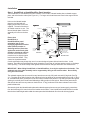
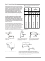
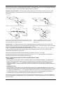
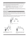
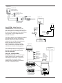
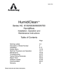
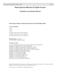
Bulletin No. 560-G
®
Installation and Operation
HumidiPack ,® HumidiPack CF,
and HumidiPackPlus™
Complete Packaged Humidifier Systems
Table of Contents
Preliminary Procedures ................................................................................................................................................. 2
Do’s & Don’ts of Location and Installation ..................................................................................................................... 3
Installation ...................................................................................................................................................................... 4
Typical Duct Installations ............................................................................................................................................... 5
Installation Concepts ..................................................................................................................................................... 6
Auxiliary Controls ........................................................................................................................................................... 9
Troubleshooting Guide ................................................................................................................................................. 11
Limited Warranty and Remedy ..................................................................................................................................... 12
Preliminary Procedures
These instructions cover the installation of the HumidiPack® and HumidiPackPlus with the Armstrong ACV
Control Valve (models listed below). The HumidiPack and HumidiPackPlus represent complete packaged
humidification systems when used in conjunction with existing boiler steam. HumidiPack may also be
used for distribution of steam generated by electric or steam-to-steam humidifiers (steam generating). In
these instances, no strainer, control valve, or steam traps are supplied. When used with boiler steam, the
systems come with the following equipment:
HumidiPack Contents:
• HumidiPack Panel
• Armstrong Inverted Bucket Steam Trap
(to be used to drip steam supply to control valve)
• Armstrong ACV Control Valve
• Armstrong In-Line Y Strainer
(to be used prior to the control valve)
• Armstrong Float & Thermostatic Steam Trap
(for condensate drainage of HumidiPack header)
(two traps are needed for HumidiPack CF)
HumidiPackPlus Contents:
• HumidiPackPlus Panel
• Armstrong Inverted Bucket Steam Trap
(to be used to drip steam supply to control valve)
• Armstrong ACV Control Valve
• Armstrong In-Line Y Strainer
(to be used prior to the control valve)
• Two Armstrong Float & Thermostatic Steam
Traps (one for header drainage, one for active
tube jacket drainage)
Step 1: Check Shipment Against Packing List.
All components are listed on the packing slip. Report any shortages immediately. If the HumidiPack or
accessories have been damaged in transit, notify us and file claim with the transportation company.
Armstrong ACV Control Valves*
Model Size
Available Pneumatic Operators
ACV-2
Armstrong C-1801
ACV-3
Honeywell MP-953D
ACV-4
Honeywell MP-953F w/Pilot
ACV-6
Positioner
Model Size
Available Electric Operators
ACV-2
Honeywell M9182A
ACV-3
Belimo
ACV-4
AF24SR or NVF24
ACV-6
If your order covers more than one
package, segregate each complete
assembly. Equipment tagging will be the
same as shown on the packing list.
Model, Serial Number, Steam Pressure
and Orifice Size are on the metal plate on
the control valve body.
Step 2: Check Local Codes.
The Armstrong HumidiPack should be
installed in accordance with all applicable
building, plumbing, and electrical codes.
*Some larger size HumidiPacks may use 2" or 2-1/2" Honeywell
control valves.
Step 3: Find HumidiPack Panel Location.
Locate all HumidiPack equipment according to the engineer’s layout or as indicated by your Armstrong
Representative. If you must locate the HumidiPack/HumidiPackPlus yourself, be sure to read and observe
the “Do’s and Don'ts” to follow.
Do’s & Don’ts of Location and Installation
All recommendations for the application of the Armstrong HumidiPack and HumidiPackPlus are based on tests
and field experience. However, they are based on duct air velocities and temperatures that are most commonly
encountered, and the recommendations may have to be modified when velocities are very high and/or
temperatures unusually low. We also reserve the right to modify recommendations without notice if
subsequent tests or experience indicate that a change should be made. For these reasons, we urge you to
check all applications with your Armstrong Representative before installation. (Illustrations applicable to both
HumidiPack and HumidiPackPlus.) See Figures 3-1 through 3-7.
2
Maintain
at Least
Specified
Vapor Trail
Coil
Dead Air
Dead Air
Filter
Do
Don't
Don't
Figure 3-1. The HumidiPack must
have airflow across the entire crosssection. Avoid fan discharges without
gradually transitioning the duct to the
HumidiPack.
Figure 3-2. The HumidiPack cannot
have daead air space off the discharge
side. When discharging into a fan
intake plenum, allow for vapor trail
length then gradually transition the duct.
Figure 3-3. Coils, duct transitions and
other obstructions must be kept at least
the specified vapor trail length downstream from the HumidiPack. This
does not apply to high efficiency filters.
Consult factory on these applications.
Beyond
Specified
Vapor
Trail
Less Than 8"
Don't
Do
Figure 3-4. Eight inch clearance (Min.)
should be maintained on discharge side
of coils.
Don't
Less Than
Specified
Vapor Trail
Duct Temp. Control
Figure 3-5. If temperature controlling devices
must be placed directly downstream from the
HumidiPack, all visible vapor must be absorbed. This may be a longer distance than
just the specified vapor trail. Consult factory if
questionable applications arise.
Beyond
Specified
Vapor Trail
Less Than
Specified
Vapor Trail
Discharge
Grill
Do
Don't
Figure 3-6. All airflow must be directed
through HumidiPack. If HumidiPack is
smaller than the duct cross-section,
HumidiPack should be positioned in
center of duct and all open area should
be blocked off. This is an exception for
some "all active" unit applications.
Do
Don't
Figure 3-7. When installing the HumidiPack directly upstream from a
discharge grill, the minimum distance shall be the specified vapor trail.
It should be noted that visible wisps of vapor can still be seen even
though the length is beyond the vapor trail. This vapor will not
condense on the grill, but may be seen in the room space.
3
Installation
Step 4: HumidiPack or HumidiPackPlus Panel Insertion
The HumidiPack or HumidiPackPlus Panel consists of the header, inboard header plate, outboard support
plate, and active/inactive tubes (See Figure 4-1). For larger units a stainless steel center tube support will be
included.
Holes on the inboard header
plate are provided and selftapping sheet metal screws are
supplied. The wall of the duct or
air handler must be cut out. The
inboard header plate of the tube
assembly will mount to the duct
wall.
Figure 4-1
Plan View
Control Valve
From Boiler
From Boiler
Strainer
2" NPT
Inlet
8.5"
Drip
Leg
B
(Overall Width)
Duct Size
Inboard
Header
Outboard
Ensure that
Plate
Header
Support
Plate
HumidiPack or
Header
Air Flow
HumidiPackPlus panel
A
orientation has air flow
Inactive Tubes
impinging against the inactive
tubes (without nozzles or
#10-16
discharge orifices) first, then
1"/12" Slope
Hex Head
1" Air Gap
Active Tubes
against the active tubes (with
Screws
Drain
Inactive Tubes
Side View
nozzles or discharge orifices).
Inboard Header Plate
F&T Trap
Both the active/inactive tubes
1" Air Gap
Drain
must be level or slightly sloped
Elevation View
F&T Trap
back toward the header. They
cannot be sloped downward.
Certain applications may dictate the use of a custom designed system without inactive tubes. In this
instance, HumidiPack/HumidiPackPlus panel orientation is such that air impinges against nozzle or discharge
orifice opening. The steam initially flows against airflow and then changes direction to flow downstream.
IMPORTANT: When lifting HumidiPack or HumidiPackPlus, do so by the eyehook on the header. The
outboard end of the tube assembly can be supported by lifting on the inactive tubes. Do not lift by
using the active tubes.
The outboard support plate is secured from any lateral movement by 3/8" panel nuts and 3/8" lag bolts (See Fig.
4-1). The holes to be drilled in the far side of the duct for the lag bolts can be sometimes difficult to locate. If this is
so, a threaded rod with a ground point on the end can be inserted in the panel nut. By sliding the panel through the
opening, the rod will pierce the duct wall indicating a drilling position for the lag bolt. Note that the panel should
slide into the duct and over any seams on the duct floor. A "leg" positioned on the lower outboard corner of the
panel facilitates this.
After ensuring both the inboard header plate and outboard support plate are secured, steam supply connections
from the Armstrong ACV control valve to the header can be made. If the HumidiPack/HumidiPackPlus is smaller
than the duct inside height and/or width the extra space should be blanked off to direct all air through panel.
4
Typical HumidiPack® Duct Installations
(HumidiPackPlus orientation is similar)
(HumidiPackPlus orientation is similar)
Inlet
Outlet Drain
Figure 5-1
Horizontal Unit Right to Left Flow
(Left Hand Header)
Figure 5-2
Vertical Unit Left Handed Steam Inlet
Inlet
Outlet
Drain
Figure 5-3
Vertical Duct Downward Flow
(Left Hand Inlet)
Installation Concepts
Condensate Drainage Options
Condensate discharged from the HumidiPack or HumidiPackPlus separator/header is at essentially
atmospheric pressure. Thus the condensate must be discharged to a drain or pumped. On many
applications, an attempt to lift condensate even a few inches will lead to potential flooding or spitting problems
from the multiple tube bank. For HumidiPackPlus units having a header drain connection and active tube
jacket drain connection, a separate F&T steam trap must be used for each. Avoid master trapping the two
connections to one steam trap. If traps discharge into a common return, install check valves (low opening
pressure) on the outlet of each steam trap.
5
Strainer
From
Boiler
Control Valve
Control Valve
From Boiler
From Boiler
Strainer
Drip
Leg
Drip
Leg
Header
Angle Iron
Mounting Frame
Header
6" - 12" Min.
Active Tubes
1" Air Gap
1"/12" Slope
X
Drain
Atmospheric
Condensate
Return
Inactive Tubes
Dispersion Manifold
Inactive Tubes
F&T Trap
Drain
F&T Trap
F&T Trap
X = 6" - 12" Min.
Figure 6-2. Drain traps discharging to floor drain.
(HumidiPackPlus shown)
Figure 6-1. Header drain trap discharging to pumped return
(HumidiPack shown)
E
D
C
Control Valve
F
Plan View
From Boiler
A
C
Overall Width
Strainer
Drip Leg
Header
Air
Flow
B
Angle Iron
Mounting Frame
(overall height)
Minimum
10" High
Water Seal
F&T Trap
1"/12" Slope
1" Air Gap
Active Tubes
Drain
Drain
Inactive Tubes
F&T Trap
Side View
Elevation View
Figure 6-3. HumidiPack CF. Drain traps discharging
to floor drain.
Figure 6-4. Condensate drained through piping loop seal.
Make sure outlet of loop seal is below bottom of HumidiPack
header.
NOTE: When installing HumidiPack for use with an electric or steam-to-steam
humidifier, minimize the length of piping run from the humidifier to HumidiPack. Piping should not extend longer than 20 feet and should be a generous
size (at least 2"). Consult factory if longer piping is necessary.
Slope piping back toward humidifier or toward a drainage point. Pipe a loop
trap to an atmospheric drain at any low points in piping run. Install, at
minimum, a 10" loop seal from the HumidiPack header drain connection.
Figure 6-5. Dual Panel Flanged HumidiPack System.
Both "P" traps drained to atmospheric drain.
2x 10" Min.
6
Step 5: Supply Steam Piping
Table 7-1. Recommended Steam Main and Branch
Line Drip Leg Sizing
Supplying quality steam (not wet) to the HumidiPack/
HumidiPackPlus is an important component for proper
operation. Care must be taken that the main supply
header is dripped sufficiently as well as the runout
piping to the Armstrong ACV Control Valve and
HumidiPack/HumidiPackPlus header. The entire
system must be designed and hooked up to prevent
accumulation of condensate at any point. The
following recommendations will help to ensure this.
Use drip legs and traps at all low spots or natural
drainage points such as: Ahead of risers; End of
mains; Ahead of expansion joints or bends; Ahead of
valves or regulators. Install drip legs and drain traps
even where there are no natural drainage points (See
Figures 7-1 thru 7-5).
H
Drip Leg
Length Minimum
M
D
Steam Main
Size (in)
Drip Leg
Diameter
(in)
Supervised
Warm-Up
(in)
Automatic
Warm-Up
(in)
1/2
3/4
1
2
3
4
6
8
10
12
14
16
18
20
24
1/2
3/4
1
2
3
4
4
4
6
6
8
8
10
10
12
10
10
10
10
10
10
10
12
15
18
21
24
27
30
36
28
28
28
28
28
28
28
28
28
28
28
28
28
30
36
On a supervised warm-up, make drip leg length at
least 1½ times the diameter of the main, but never less
than 10". Make drip legs on automatic warm-ups a
minimum of 28" in length. For both methods, it is a
good practice to use a drip leg the same diameter as
the main up to 4" pipe size and at least ½ of the
diameter of the main above that, but never less than 4". See Table 7-1.
10' or Less
Pitch 1/2" per 1 ft.
Runout oversized
One pipe size or more
Figure 7-1. Trap draining strainer
ahead of PRV.
Figure 7-2. Trap draining drip leg at
riser. Distance "H" in inches ÷ 28=
psi static head for forcing water
through the trap.
Figure 7-3. Piping for runout less than
10 ft. No trap required unless pitch
back to supply header is less than ½"
per ft.
More
Than
10'
M
D
H
Pitch 1/2" per 10 ft.
Figure 7-4. Trap draining drip leg on main.
Figure 7-5. Piping for runout greater than 10'. Drip leg and trap required ahead
of control valve. Strainer ahead of control valve can serve as drip leg if
blowdown connection runs to an inverted bucket trap. This will also minimize
the strainer cleaning problem. Trap should be equipped with an internal check
valve or swing check installed ahead of the trap.
7
Shown below are typical configurations depicting proper piping practices. Do not use smaller pipe sizes than
what the connections are on the supplied control valve. Take steam supply from the top of supply main-never
from the side or bottom. See Steam Pipe Capacities tables on Page 12.
Expansion and Contraction. With average length of supply line, the dimension change from hot to cold
should not exceed 2". Provide piping with (3) 90° elbows to obtain swing to take care of expansion and
contraction.
Steam Main
Run Out
Steam Main
Condensate Return
or Drain
Run Out
Armstrong
Strainer
Armstrong ACV
Control Valve
Trap
To Condensate
Return/Drain
To HumidiPack
Header
Trap
Dirt Leg
Figure 8-1. Typical runout less than 30 feet long.
Figure 8-2. Typical long runout of 30 feet or more.
Steam Main
10' Minimum
If More Than
10'
Run Out
Strainer
Armstrong Strainer
Condensate Return
or Drain
Steam Main
Armstrong ACV
Control Valve
PRV Is
Single Seated,
Dead End Type
Trap
Strainer
Blowdown
Connection
To Strainer
Control Valve
HumidiPack Header
To HumidiPack
Header
To Control Valve
HumidiPack Header
Trap
Dirt Leg
Figure 8-3. If the supply steam to the control valve exceeds the control
valve pressure rating, an Armstrong pressure reducing valve may need
to be installed after the Y strainer as shown.
Figure 8-4. Piping when more than one HumidiPack or HumidiPackPlus is fed from the same
steam runout.
Control Valve. The Armstrong control valve is installed in the steam supply line after the Y strainer and
supplies steam to the header of the HumidiPack/HumidiPackPlus panel. The steam supply connection on the
top of the HumidiPack/HumidiPackPlus header is either 1" NPT or
2" NPT. The control valve connection size may be different. In these cases, reduce from the 2" connection
on the HumidiPack/HumidiPackPlus header down to the Armstrong control valve size by bushing the 2"
HumidiPack/HumidiPackPlus connection.
Piping of air supply to pneumatic control valves are discussed in Figures 9-1, 9-2 and
9-3 while wiring for electric control vales is discussed in Figure 10-1. For more installation information of
Armstrong Control Valves, see Installation Bulletin IB-58.
Step 6: Install Armstrong Float & Thermostatic Steam Trap(s)
a) HumidiPack
The connection on the bottom of the HumidiPack header is for condensate drainage. The supplied Armstrong Float & Thermostatic steam trap should be piped from this connection as illustrated in Figure 4-1.
Make sure a distance of 6" - 12" is maintained between the top of the F&T trap and the bottom of the
HumidiPack header. A second connection is used for HumidiPack CF and the same guidelines should be
followed.
b) HumidiPackPlus
The connection on the bottom of the HumidiPackPlus header is for condensate drainage and one of the
supplied Armstrong Float & Thermostatic steam traps should be installed in this location as shown in Figure
6-2. Make sure a distance of 6" - 12" is maintained between the top of the F&T trap and the bottom of the
HumidiPackPlus header. The second supplied Armstrong Float & Thermostatic steam trap should be
installed at the active tube jacketing drain connection as illustrated in Figure 6-2.
The discharge pressure from the steam traps is at essentially atmospheric pressure. Thus, the condensate
must be discharged to a suitable drain, or a condensate pump. It cannot be connected to an overhead return
without pumping.
8
NOTE: The Armstrong CS Series, EHU-600 Series, and EHU-700 Series Humidifiers, along with the
Armstrong HC-4000 Series HumidiClean and GFH Series Gas Fired HumidiClean can be used in conjunction
with the HumidiPack. The HumidiPack will not include the control valve, steam traps or strainer in these
applications. (HumidiPackPlus is not compatible with these humidifiers.)
Step 9A: Install Pneumatic Piping in accordance with Figures 9-1, 9-2, or 9-3 or engineer’s layout.
a. Control Air Supply. Unless otherwise specified, air supply for Armstrong Humidifiers
should be 20 psig maximum. This air must be clean and dry.
b. Air Piping. ¼” plastic tubing or equivalent is recommended for all air connections.
Step 10A. Install and Connect Humidity Controller as specified by the design engineer in accordance with
manufacturer’s instructions. If location is not specified, it may be installed in the area controlled or in either the
return air or exhaust air ducts.
Auxiliary Controls
High Limit Duct Humidity Controller. A high limit humidistat is recommended downstream from the
HumidiPack panel. The location of the high limit humidistat should be beyond the wetable vapor distance but
not beyond any filters. The purpose of the high limit humidistat is to override the controlling humidistat. This
high limit humidistat automatically prevents local saturation at the point of steam introduction. It also prevents
overloading the duct with vapor in the event of failure of air conditioning system components, incorrect control
settings, or tampering. See Figure 9-3.
Interlocks for Shutdowns. Humidifiers should be interlocked with fans for shutdown on power failure or other
system trouble. Interlock should be such that control valve will bleed its control air to atmosphere on a system
shutdown rather than be locked in its position at time of shutdown. See Figure 9-2.
Duct High Limit
Humidity Controller
Gauge
Humidity
Controller
Shut Off
Valve
Main Line
15 P.S.I.
Armstrong
Control Valve
Figure 9-1. Standard compressed air hook-up for
pneumatic control.
Line In
120V or 240V
Duct
Fan Motor
Electric Pneumatic
Valve (120V or 240V)
Duct High
Limit Humidity
Controller
R
Gauge
S
Duct
Humidity
Controller
R
S
Gauge
Shut Off
Valve
Main Line
15 P.S.I.
Main Line
15 P.S.I.
Humidity
Controller
Armstrong
Control Valve
Armstrong
Control Valve
Figure 9-2. Compressed air hook-up for air operated
humidifiers incorporating safety interlock for shut down
in the event of power failure to fan.
Figure 9-3. Compressed air hook-up for humidifiers
utilitzing two Armstrong Duct Humidity Controllers,
one as the humidity controller, the other as a high
limit controller.
9
Figure 10-1
H915 (Series 90)
Humidity Controller
If High Limit Not Used,
Wire (R) Directly to (R)
HC-201 High Limit
Duct Humidity Controller
(When Used)
Fan Interlock
Figure 10-2
Belimo AF24-SR
or NVF24-MFT-E
Transformer
M9182A (Series 90)
Motorized Operator
Line Voltage
Step 9E (EM): Make Electrical
Connections as recommended by the
24 VAC
Transformer
A9023
Pressure
Switch
(Optional)
manufacturers of the operators and controls.
Also, use Figures 10-1 through 10-3 as a guide.
Be sure wiring is adequate for the requirements
of the system. Check voltage ratings on
operator nameplate.
B1564 Electric
Temperature
Switch (Optional)
A8581
High Limit
Humidistat
(Optional)
“EM” Series electric motor operated humidifiers
are furnished with a choice of Honeywell
M9182A operators (24 watts at 24v, 60 Hz
suitable for 120v or 240v with transformer),
Belimo AF24SR or NVF24 electric
motorized operators. These operators
Figure 10-3
may be controlled by compatible humidity
Primary Voltage
120, 208, 240, 480 VAC
controllers or electronic humidity panels.
Armstrong
0-10 VDC Stat
A18609 or A18610
4-20 mA Humidistat
or Controller
For all EM operators mount operator so
that the motor shaft is parallel to the
floor (or horizontal).
Neg. (-)
Optional Fan
Interlock or
Pressure Switch
(Open on Fault)
AMW#A9023
Step 10E: Install and Wire
Humidity Controller as specified by the
design engineer and in accordance with
manufacturer's instructions. If location is
not specified, the controller may be
installed in area controlled or in either the
return air or exhaust air ducts.
Optional
Temperature
Switch (Open on Fault)
AMW#B1564
Input Impedance On Resistor
Board is 66 OHMS
Dip Settings Shown Are For
One (1) M9182A Motor With
4-20 mA Control Signal
10
Optional
High Limit
Humidistat
(Open on %RH
Rise) AMW#A8581
(+) Pos.
Troubleshooting Guide
I.
HumidiPack/HumidiPackPlus will not discharge steam.
A. Control System Fault
1. Control valve operator-does the valve open and close as the control signal varies
between 0% to 100%?
B. Steam System Malfunction
1. Strainer screen before control valve is plugged.
2. Pressure reducing valve malfunction.
II. HumidiPack/HumidiPackPlus discharges continuously even though
humidity has exceeded desired level.
A. Humidity controller or pneumatic operator out of calibration.
B. Control valve malfunction.
1. Valve stem on control valve "frozen" to stem seal due to unusual chemical or
corrosive conditions in steam system.
2. Operator spring on pneumatic control valve broken.
3. Dirt or scale between valve and seat in control valve - blow down and clean strainer.
III. Low Steam Output
A. Control system
1. Humidity controller or pneumatic operator not calibrated
or malfunctioning.
2. Control valve faulty.
B. Steam system
1. Piping not sized correctly.
IV. HumidiPack/HumidiPackPlus "Spitting"
A. Lift or back pressure after float & thermostatic steam trap(s) is too great for steam
supply pressure resulting in flooded HumidiPack panel.
B. Supply steam not properly dripped.
C. HumidiPackPlus ONLY: Jacketing supply steam to the active tubes may be isolated
or off.
D. The steam trap draining HumidiPack/HumidiPackPlus header has failed closed.
E. HumidiPackPlus ONLY: The steam trap draining the active tube jackets has failed
closed.
F. Tubes on the panel are sloped away from instead of towards the header.
G. Not enough "head" distance in between the bottom of the HumidiPack/HumidiPackPlus
header and top of F&T drip traps.
H. Steam trap draining HumidiPack/HumidiPackPlus header is not isolated from a common
return line (check valves not installed after trap.)
I. Verify sufficient jacketing pressure is available for HumidiPackPlus units.
Contact factory for acceptable guidelines.
11
Steam Pipe Capacities
For computing ability of piping to deliver an adequate supply of
steam to humidifier. Capacities shown are in pounds per hour.
Table 1 Steam Pipe Capacity at 5 psi
Pipe Size
Pressure Drop, psi per 100 ft. of pipe length
(in)
1/8
1/4
1/2
3/4
1
-24
31
44
54
62
1
-52
68
97
120
140
1-1/4
-81
100
150
180
210
1-1/2
-160
210
300
370
430
2
-270
350
500
610
710
2-1/2
-Table 2 Steam Pipe Capacity at 15 psi
Pipe Size
Pressure Drop, psi per 100 ft. of pipe length
1/8
1/4
1/2
3/4
1
2
(in)
27
38
53
65
76
110
1
59
83
120
140
160
230
1-1/4
91
130
180
220
260
360
1-1/2
180
260
370
450
520
740
2
300
430
600
740
860
1210
2-1/2
Table 3 Steam Pipe Capacity at 25 psi
Pipe Size
Pressure Drop, psi per 100 ft. of pipe length
1/8
1/4
1/2
3/4
1
2
(in)
15
21
30
37
43
60
3/4
30
43
61
75
86
122
1
67
95
130
160
190
260
1-1/4
100
140
210
250
290
410
1-1/2
210
300
420
510
590
840
2
340
490
690
850
980
1380
2-1/2
Table 4 Steam Pipe Capacity at 50 psi
Pressure Drop, psi per 100 ft. of pipe length
Pipe Size
1/4
1/2
3/4
1
2
5
(in)
27
38
47
54
76
120
3/4
54
77
94
110
150
240
1
120
170
210
240
340
530
1-1/4
180
260
320
370
520
830
1-1/2
370
530
650
750
1060
1680
2
620
870
1070 1240
1750
2760
2-1/2
Limited Warranty and Remedy
Armstrong International, Inc. (“Armstrong”) warrants to the
original user of those products supplied by it and used in the
service and in the manner for which they are intended, that such
products shall be free from defects in material and workmanship
for a period of one (1) year from the date of installation, but not
longer than 15 months from the date of shipment from the
factory, [unless a Special Warranty Period applies, as listed
below]. This warranty does not extend to any product that has
been subject to misuse, neglect or alteration after shipment from
the Armstrong factory. Except as may be expressly provided in
a written agreement between Armstrong and the user, which is
signed by both parties, Armstrong DOES NOT MAKE ANY
OTHER REPRESENTATIONS OR WARRANTIES, EXPRESS
OR IMPLIED, INCLUDING, BUT NOT LIMITED TO, ANY
IMPLIED WARRANTY OF MERCHANTABILITY OR ANY
IMPLIED WARRANTY OF FITNESS FOR A PARTICULAR
PURPOSE.
The sole and exclusive remedy with respect to the above limited
warranty or with respect to any other claim relating to the
products or to defects or any condition or use of the products
supplied by Armstrong, however caused, and whether such
claim is based upon warranty, contract, negligence, strict liability,
or any other basis or theory, is limited to Armstrong’s repair or
replacement of the part or product, excluding any labor or any
other cost to remove or install said part or product, or at
Armstrong’s option, to repayment of the purchase price. As a
condition of enforcing any rights or remedies relating to
Armstrong products, notice of any warranty or other claim
relating to the products must be given in writing to Armstrong: (i)
within 30 days of last day of the applicable warranty period, or (ii)
within 30 days of the date of the manifestation of the condition or
occurrence giving rise to the claim, whichever is earlier. IN NO
EVENT SHALL ARMSTRONG BE LIABLE FOR SPECIAL,
DIRECT, INDIRECT, INCIDENTAL OR CONSEQUENTIAL
DAMAGES, INCLUDING, BUT NOT LIMITED TO, LOSS OF
USE OR PROFITS OR INTERRUPTION OF BUSINESS. The
Limited Warranty and Remedy terms herein apply notwithstanding any contrary terms in any purchase order or form submitted
or issued by any user, purchaser, or third party and all such
contrary terms shall be deemed rejected by Armstrong.
Special Warranty Periods are as follows:
Series EHU-700 Electric Steam Humidifier, Series HC-4000
HumidiClean Humidifier and GFH Gas Fired Humidifier with
Ionic Beds:
Two (2) years after installation, but not longer than 27 months
after shipment from Armstrong’s factory.
© 2001 Armstrong International, Inc.
Designs, materials, and performance ratings are subject to
change without notice.
®
Armstrong Hot Water Group
816 Maple Street, Three Rivers, Michigan 49093 - USA Phone: (269) 273-1415 Fax: (269) 273-9500
Bult. 560-G 3M 1/05
www.armstrong-intl.com
Printed in U.S.A.