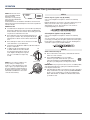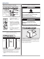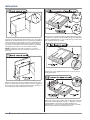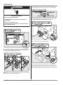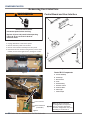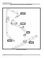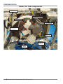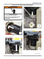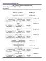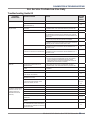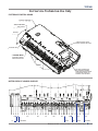
1
KD-15 TECHNICAL EDUCATION 2013 Stainless Steel Tall Tub Dishwasher KUDE20FB*0, KUDE20IX*9, KUDE40FX*6, KUDE48FX*5, KUDE50CX*9, KUDE50FB*0, KUDE60FX*5, KUDE60HX*5, KUDE70FX*5, KUDL15FX*6 *All Colors JOB AID W10573282 FORWARD This KitchenAid Job Aid, "2013 Stainless Steel Tall Tub Dishwasher" (Part No. W10573282), provides the In-Home Service Professional with information on the installation, operation, and service of the “Global Wash System" with variable speed wash and drain motors. For specific operating information on the model being serviced, refer to the “Use and Care Guide” provided with the dishwasher. GOALS AND OBJECTIVES The goal of this Job Aid is to provide information that will enable the In-Home Service Professional to properly diagnose malfunctions and repair the "KitchenAid 2013 Stainless Steel Tall Tub Dishwasher.” The objectives of this Job Aid are to: • Understand and follow proper safety precautions. • Successfully troubleshoot and diagnose malfunctions. • Successfully perform necessary repairs. • Successfully return the dishwasher to its proper operational status. WHIRLPOOL CORPORATION assumes no responsibility for any repairs made on our products by anyone other than authorized In-Home Service Professionals. Copyright © 2013, Whirlpool Corporation, Benton Harbor, MI 49022 ii n KitchenAid 2013 Tall Tub Stainless Steel Dishwasher TABLE OF CONTENTS KitchenAid 2013 Stainless Steel Tall Tub Dishwasher SECTION 1 — GENERAL INFORMATION DISHWASHER SAFETY..........................................................................................................................1-2 BEFORE USING YOUR DISHWASHER...................................................................................................1-3 MODEL & SERIAL NUMBER LABEL......................................................................................................1-4 TECH SHEET LOCATION........................................................................................................................1-4 MODEL & SERIAL NUMBER NOMENCLATURE....................................................................................1-5 PRODUCT SPECIFICATIONS.................................................................................................................1-6 PARTS & FEATURES..............................................................................................................................1-7 NOTES..................................................................................................................................................1-8 SECTION 2 — OPERATION START-UP / QUICK REFERENCE...........................................................................................................2-2 QUICK STEPS........................................................................................................................................2-3 DISHWASHER USE...............................................................................................................................2-3 CYCLE & OPTION DESCRIPTIONS.........................................................................................................2-5 DISHWASHER FEEDBACK SECTION.....................................................................................................2-8 DISHWASHER FEATURES.....................................................................................................................2-9 FILTRATION SYSTEM..........................................................................................................................2-11 DISHWASHER CARE...........................................................................................................................2-13 CONSUMER TROUBLESHOOTING GUIDE..........................................................................................2-14 NOTES................................................................................................................................................2-16 SECTION 3 — INSTALLATION DISHWASHER SAFETY..........................................................................................................................3-2 INSTALLATION REQUIREMENTS..........................................................................................................3-4 LOCATION REQUIREMENTS.................................................................................................................3-5 DRAIN REQUIREMENTS.......................................................................................................................3-7 ELECTRICAL REQUIREMENTS..............................................................................................................3-7 INSTALLATION INSTRUCTIONS............................................................................................................3-8 DETERMINE CABINET OPENING........................................................................................................3-15 INSTALL DOOR HANDLE.....................................................................................................................3-16 INSTALL CUSTOM PANEL...................................................................................................................3-16 CHOOSE ATTACHMENT OPTION........................................................................................................3-19 PREPARE WATER SUPPLY LINE..........................................................................................................3-20 CONNECT WATER SUPPLY..................................................................................................................3-22 CONNECT TO DRAIN..........................................................................................................................3-22 MAKE DIRECT WIRE ELECTRICAL CONNECTION...............................................................................3-23 SECURE DISHWASHER TO CABINET OPENING..................................................................................3-25 COMPLETE INSTALLATION.................................................................................................................3-26 NOTES................................................................................................................................................3-28 SECTION 4 — COMPONENT ACCESS INSULATION BLANKET.........................................................................................................................4-2 DOOR LATCH STRIKE............................................................................................................................4-2 ADJUSTABLE DOOR SPRINGS..............................................................................................................4-3 WATER INLET & DRAIN HOSE..............................................................................................................4-3 OVERFILL ASSEMBLY...........................................................................................................................4-4 ACCESSING DOOR COMPONENTS.......................................................................................................4-5 KitchenAid 2013 Tall Tub Stainless Steel Dishwasher n iii REMOVING USER INTERFACE..............................................................................................................4-6 REMOVING LATCH ASSEMBLY.............................................................................................................4-7 REMOVING ELECTRONIC CONTROL BOARD.......................................................................................4-8 REMOVING DISPENSER ASSEMBLY.....................................................................................................4-9 SPRAY ARMS, FEED TUBE, AND MANIFOLD......................................................................................4-10 TUB COMPONENTS — STAINLESS STEEL TUB MODELS....................................................................4-11 REMOVING THE UPPER RACK(S).......................................................................................................4-12 REMOVING LOWER SPRAY ARM.......................................................................................................4-13 REMOVING FILTERS...........................................................................................................................4-14 REMOVING PROSCRUB MANIFOLD..................................................................................................4-15 REMOVING DIVERTER DISK..............................................................................................................4-15 UNDER THE TUB COMPONENTS.......................................................................................................4-18 HEATER..............................................................................................................................................4-19 REMOVING SUMP ASSEMBLY & DRAIN PUMP.................................................................................4-20 REMOVING OPTICAL WATER INDICATOR.........................................................................................4-23 REMOVING DIVERTER MOTOR.........................................................................................................4-24 WASH MOTOR REPLACEMENT..........................................................................................................4-25 SECTION 5 — DIAGNOSTICS & TROUBLESHOOTING SAFETY WARNINGS.............................................................................................................................5-2 WASH CYCLES......................................................................................................................................5-3 SERVICE DIAGNOSTIC CYCLE...............................................................................................................5-4 SERVICE DIAGNOSTIC CYCLE NOTES...................................................................................................5-5 DIAGNOSTIC GUIDE.............................................................................................................................5-5 SERVICE DIAGNOSTICS WITH ERROR CODES......................................................................................5-6 SERVICE ERROR CODES.......................................................................................................................5-7 TROUBLESHOOTING GUIDE..............................................................................................................5-12 SECTION 6 — TESTING SAFETY WARNINGS.............................................................................................................................6-2 WIRING DIAGRAM...............................................................................................................................6-3 CONTROL BOARD INFORMATION/SPECS...........................................................................................6-4 COMPONENT TESTING........................................................................................................................6-4 ELECTRONIC CONTROL BOARD...........................................................................................................6-5 GENERAL THEORY OF OPERATION......................................................................................................6-6 POWER CHECK.....................................................................................................................................6-6 DOOR SWITCH CIRCUIT.......................................................................................................................6-7 FILL CIRCUIT.........................................................................................................................................6-8 DISPENSER CIRCUIT.............................................................................................................................6-9 WATER HEATING / HEAT DRY............................................................................................................6-10 WATER SENSING WITH OWI SENSOR................................................................................................6-11 DIVERTER MOTOR.............................................................................................................................6-12 DIVERTER SENSOR / POSITION SWITCH...........................................................................................6-13 WASH MOTOR (VARIABLE SPEED).....................................................................................................6-14 DRAIN MOTOR (VARIABLE SPEED)....................................................................................................6-15 VENT WAX MOTOR............................................................................................................................6-16 VENT FAN...........................................................................................................................................6-17 USER INTERFACE................................................................................................................................6-18 PRODUCT SPECIFICATIONS & WARRANTY INFORMATION SOURCES (inside back cover) iv n KitchenAid 2013 Tall Tub Stainless Steel Dishwasher GENERAL INFORMATION Section 1: General Information This section provides general safety, parts, and information for the “KitchenAid Stainless Steel Tall Tub Dishwasher.” ■■ Dishwasher Safety ■■ Before Using Your Dishwasher ■■ Model & Serial Number Label ■■ Tech Sheet Locations ■■ Model & Serial Number Nomenclature ■■ Product Specifications ■■ Parts & Features ■■ Notes KitchenAid 2013 Tall Tub Stainless Steel Dishwasher n 1-1 GENERAL INFORMATION Dishwasher Safety Your safety and the safety of others are very important. We have provided many important safety messages in this manual and on your appliance. Always read and obey all safety messages. This is the safety alert symbol. This symbol alerts you to potential hazards that can kill or hurt you and others. All safety messages will follow the safety alert symbol and either the word “DANGER” or “WARNING.” These words mean: DANGER WARNING You can be killed or seriously injured if you don't immediately follow instructions. You can be killed or seriously injured if you don't follow instructions. All safety messages will tell you what the potential hazard is, tell you how to reduce the chance of injury, and tell you what can happen if the instructions are not followed. IMPORTANT SAFETY INSTRUCTIONS WARNING: When using the dishwasher, follow basic precautions, including the following: ■■ Read all instructions before using the dishwasher. ■■ Use the dishwasher only for its intended function. ■■ Use only detergents or rinse agents recommended for use in a dishwasher, and keep them out of the reach of children. ■■ When loading items to be washed: 1) Locate sharp items so that they are not likely to damage the door seal; and 2) Load sharp knives with the handles up to reduce the risk of cut-type injuries. ■■ Do not wash plastic items unless they are marked “dishwasher safe” or the equivalent. For plastic items not so marked, check the manufacturer’s recommendations. ■■ Do not touch the heating element during or immediately after use. ■■ Do not operate the dishwasher unless all enclosure panels are properly in place. ■■ Do not tamper with controls. ■■ Do not abuse, sit on, or stand on the door, lid, or dish racks of the dishwasher. ■■ To reduce the risk of injury, do not allow children to play in or on the dishwasher. ■■ Under certain conditions, hydrogen gas may be produced in a hot water system that has not been used for two weeks or more. HYDROGEN GAS IS EXPLOSIVE. If the hot water system has not been used for such a period, before using the dishwasher turn on all hot water faucets and let the water flow from each for several minutes. This will release any accumulated hydrogen gas. As the gas is flammable, do not smoke or use an open flame during this time. ■■ Remove the door or lid to the washing compartment when removing an old dishwasher from service or discarding it. SAVE THESE INSTRUCTIONS State of California Proposition 65 Warnings: WARNING: This product contains one or more chemicals known to the State of California to cause cancer. WARNING: This product contains one or more chemicals known to the State of California to cause birth defects or other reproductive harm. 1-2 n KitchenAid 2013 Stainless Steel Tall Tub Dishwasher GENERAL INFORMATION Before Using Your Dishwasher GROUNDING INSTRUCTIONS Tip Over Hazard Do not use dishwasher until completely installed. Do not push down on open door. Doing so can result in serious injury or cuts. • For a grounded, cord-connected dishwasher: The dishwasher must be grounded. In the event of a malfunction or breakdown, grounding will reduce the risk of electric shock by providing a path of least resistance for electric current. The dishwasher is equipped with a cord having an equipment-grounding conductor and a grounding plug. The plug must be plugged into an appropriate outlet that is installed and grounded in accordance with all local codes and ordinances. WARNING: Improper connection of the equipmentgrounding conductor can result in a risk of electric shock. Check with a qualified electrician or service representative if you are in doubt whether the dishwasher is properly grounded. Do not modify the plug provided with the dishwasher; if it will not fit the outlet, have a proper outlet installed by a qualified electrician. • For a permanently connected dishwasher: The dishwasher must be connected to a grounded metal, permanent wiring system, or an equipment-grounding conductor must be run with the circuit conductors and connected to the equipment-grounding terminal or lead on the dishwasher. SAVE THESE INSTRUCTIONS Electrical Shock Hazard Electrically ground dishwasher. Connect ground wire to green ground connector in terminal box. Do not use an extension cord. Failure to follow these instructions can result in death, fire, or electrical shock. • Install where dishwasher is sheltered from the elements. Avoid possible rupture of fill valve from freezing. Such ruptures are not covered by the warranty. See “Storing” section for winter storage information. • Install and level dishwasher on a floor that will hold the weight, and in an area suitable for its size and use. • Remove all shipping plugs from hoses and connectors (such as the cap on the drain outlet) before installing. See Installation Instructions or complete information. KitchenAid 2013 Tall Tub Stainless Steel Dishwasher n 1-3 GENERAL INFORMATION Model & Serial Number Label Model & Serial Number Label Location Tech Sheet Location Tech Sheet Location (Behind Toe Kick Panel) 1-4 n KitchenAid 2013 Stainless Steel Tall Tub Dishwasher GENERAL INFORMATION Model & Serial Number Nomenclature MODEL NUMBER K UD E 60 F X BL 5 INTERNATIONAL SALES OR MARKETING CHANNEL K = KITCHENAID BRAND PRODUCT IDENTIFIER PD = Convertible/Portable UD = Undercounter E = TRI-FILTER SYSTEM SERIES CONFIGURATION FEATURES F = Fully Integrated Door C = 2.5” Console w/Display H = Heritage S = Water Softener I = 2.5” Console YEAR OF MODEL INTRODUCTION X = 2010 B = CU Model COLOR CODE WH = White BT = Biscuit SS = Stainless Steel SP = Stainless Proline BL = Black PA = Panel Ready ENGINEERING CHANGE 0 = Basic Release; 1 = First Revision; 2 = Second Revision SERIAL NUMBER F 2 25 10000 MANUFACTURING SITE F = FINDLAY, OH YEAR OF MANUFACTURE 2 = 2012 WEEK OF MANUFACTURE PRODUCT SEQUENCE NUMBER KitchenAid 2013 Tall Tub Stainless Steel Dishwasher n 1-5 GENERAL INFORMATION Product Specifications DISHASHER SPECIFICATIONS Line Voltage: Frequency: Amps: Low Volts Power Supply: 120V AC 60 Hz 10A +15V, +13V, +5V, +3.3 Water Pressure: Supply Water Temperature: Control: Wash Motor: Drain Motor: Diverter Motor: Fill Valve: Heater: Dispenser: Spray Arm Motor: Fan Motor: Sensors: Switches: TCO / Bi‐Metal: Fuses: 120 psi Max, 20 psi Min Minimum ‐ 120° F (49° C) Electronic Control w/Integrated VSM Control 3‐Phase Variable Speed Motor (VSM) 3‐Phase Variable Speed Motor (VSM) 120V AC 120V AC 120V AC 120V AC 120V AC (some models) +5V DC (some models) Temperature Sensor Water Sensor (OWI) Spray Arm Sensor (some models) Diverter Position Switch (5V DC) Door Switch (13V DC) Float Switch (120V AC) Incorporated into Control Board (Penninsula Slots) Line (L1) Fuse Motor Control Fuse Triac Fuse Lower Wash Arm: Upper Wash Arm: Filtration: ProScrub: Water Softener Model: 1-6 n KitchenAid 2013 Stainless Steel Tall Tub Dishwasher "S" Design Straight Design 3‐Stage Filter System Available on certain models KUDE60SXSS4 GENERAL INFORMATION Parts & Features Parts and Features ProScrub® (on some models) powerful jets target water toward pots, pans, or casserole dishes loaded in the back of the dishwasher to clean stubborn messes. Upper level wash Water feed tube Model and serial number label Pressurized spray nozzles and variable speed motor provide effective cleaning. Water inlet opening Lower spray arm Heating element Overfill protection float Rinse aid dispenser reduces spotting and improves drying. EQ Filtration System removes soil from water and improves cleaning action. Detergent dispenser Control panel Premium top rack adjusters Culinary tool rack/3rd level rack (on some models) Flexible fold-down tines (on some models) Cup shelves with stemware holder Rack handle Upper spray arm TOP RACK Silverware basket Flexible fold-down tines Culinary Caddy® utensil basket (on some models) BOTTOM RACK KitchenAid 2013 Tall Tub Stainless Steel Dishwasher n 1-7 4 GENERAL INFORMATION Notes 1-8 n KitchenAid 2013 Stainless Steel Tall Tub Dishwasher OPERATION Section 2: Operation This section provides operational use and care information for the “KitchenAid Stainless Steel Tall Tub Dishwasher.” ■■ Start-Up / Quick Reference ■■ Quick Steps ■■ Dishwasher Use ■■ Cycle and Option Descriptions ■■ Dishwasher Feedback Section ■■ Dishwasher Features ■■ Filtration System ■■ Dishwasher Care ■■ Consumer Troubleshooting Guide ■■ Notes KitchenAid 2013 Stainless Steel Tall Tub Dishwasher n 2-1 OPERATION Start-Up / Quick Reference Start-Up / Quick Reference (varies by model) Clean EQ Wash System removable filters to maintain peak performance. Cleaning the filters periodically helps keep the dishwasher working at peak performance. The filters can be found at the bottom center of your dishwasher. See the “Filtration System” section for information on removing and maintaining the filters. SH DOWN & TU RN O C L L O CK PU K U N The most advanced and versatile cycle. ProWash™ cycle senses the load size, soil amount, and toughness of soil, to adjust the cycle for optimal cleaning using only the amount of water and energy needed. The ProWash™ and Heavy Duty cycles are recommended for tough soil. No need to prerinse dishes; just scrape and load. ProScrub® Option for loading to clean baked-on food (some models) IMPORTANT: Do not block detergent dispenser. Tall items placed in the lower rack may block the dispenser door. Cookie sheets and cutting boards loaded on the left-hand side of the dishwasher can easily block the dispenser. If detergent is inside of the dispenser or on the bottom of the tub after the cycle is complete, the dispenser was blocked. When the ProScrub® option is selected, it provides a concentrated wash on the back of the lower dish rack for hard-to-clean dishes. Place these dishes with the soiled surface of the dish toward the ProScrub® spray jets in the lower rack of the dishwasher. Press START/RESUME every time you add a dish. IMPORTANT: If anyone opens the door (such as, for adding a dish, even during the Delay Hours option), the Start/Resume button must be pressed each time. Drying - Rinse Aid is essential. You must use a drying agent such as a rinse aid for good drying performance (sample included). Rinse aid along with the Heat Dry or ProDry™ option will provide best drying and avoid excessive moisture in the dishwasher interior. ProWash™ cycle for optimal cleaning USE RINSE AID FOR BETTER DRYING Full Lock Add Refill If the Start/Resume button is located on top of door: Push door firmly closed within 3 seconds of pressing START/RESUME. If the door is not closed within 3 seconds, the Start/ Resume button LED will flash, an audible tone will be heard, and the cycle will not start. or Proper Detergent Dosing 1 Hour Wash - When you need fast results. Efficient dishwashers run longer to save water and energy, just as driving a car slower saves on gas. When you need fast results, the 1 Hour Wash will clean your dishes using slightly more water and energy. Select the Heat Dry or ProDry™ option to speed drying times (adds approximately 27 to 35 minutes to the 1 Hour Wash cycle) It is possible to use too much detergent in your dishwasher. This can lead to etching of your dishes. See “Add Detergent” in the “Dishwasher Use” section, to determine the amount of detergent needed based on your water hardness. 2-2 n KitchenAid 2013 Stainless Steel Tall Tub Dishwasher 5 OPERATION Quick Steps 1 1 Prepare and load dishwasher. Prepare and load dishwasher. 2 2 Add detergent for cleaning and Add detergent rinse aid for for cleaning and drying. rinse aid for drying. Quick Steps Quick Steps 3 3 Select a cycle and option. 4 4 Start dishwasher. Select a cycle and option. NOTE: If the Start/Resume button is located Start dishwasher. on the top of door, push door firmly closed NOTE: the Start/Resume is located within 3Ifseconds of pressingbutton START/RESUME. on the top of door, push door firmly closed within 3 seconds of pressing START/RESUME. Dishwasher Use Dishwasher Use Dishwasher Use ■ When loading silverware, always place sharp STEP 1 STEP 1 Prepare and Load the Dishwasher ■ IMPORTANT: leftover food, bones, toothpicks and other Prepare andRemove Load the Dishwasher hard items from the dishes. Remove labels from containers before IMPORTANT: Remove leftover food, bones, toothpicks and other washing. hard items from the dishes. Remove labels from containers before washing. items pointing down. Mix items in each When silverware, place sharp sectionloading of the basket withalways some pointing up items pointing down. Mix nesting. items in Spray each and some down to avoid section of the nested basket items. with some pointing up cannot reach and some down to avoid nesting. Spray cannot reach nested items. STEP 2 Add Detergent ■ ■ ■ ■ ■ ■ ■ ■ ■ ■ ■ ■ ■ ■ Upper rack Lower rack Upper rack Lower rack Make sure nothing keeps spray arm(s) from spinning freely. It is important for the water Make nothing keepssurfaces. spray arm(s) from spray sure to reach all soiled spinning freely. It is important for the water spray to reach all soiled surfaces. Hard Water Soft Water Hard Water Soft Water Make sure that when the dishwasher door is closed no items are blocking the detergent dispenser. Make sure that when the dishwasher door is closed no items Items shouldthe be loaded with soiled surfaces facing down and are blocking detergent dispenser. inward to the spray as shown. This will improve cleaning and Items dryingshould results.be loaded with soiled surfaces facing down and inward to the spray as shown. This will improve cleaning and Avoid items like bowls or plates that may trap food. dryingoverlapping results. Place plastics, small plates glasses in the upper rack.food. Avoid overlapping items likeand bowls or plates that may trap Wash only plastic items marked “dishwasher safe.” Place plastics, small plates and glasses in the upper rack. To avoid thumping/clattering noises during operation, Wash only plastic items marked “dishwasher safe.” load dishes so they do not touch one another. Make sure lightweight To avoid thumping/clattering load items are secured in the noises racks. during operation, load dishes so they do not touch one another. Make sure lightweight Improper can cause load itemsloading are secured in thedishes racks.to be chipped or damaged. When loading glasses or mugs, it is best to load these items in Improper loading can cause dishes to be them chipped ortines, damaged. between rows of tines instead of loading over as When glasses or mugs, it is best to load these items in shownloading in the image above. between rows of tines instead of loading them over tines, as shown in the image above. ■ ■ ■ ■ 6 6 STEP 2 NOTE: If you do not plan to run a wash cycle soon, run a rinse Add Detergent cycle. Do not use detergent. NOTE: If you do not plan to run a wash cycle soon, run a rinse ■ Use dishwasher detergent only. Add powder, liquid cycle. Doautomatic not use detergent. or tablet detergent just before starting a cycle. ■ Use automatic dishwasher detergent only. Add powder, liquid ■ Fresh automatic or tablet detergent just before starting a cycle. A dishwasher detergent ■ Fresh automatic A results in better Hard Water dishwasher detergent Soft Water cleaning. Store tightly results in better B Hard Water closed detergent C SoftPREWater cleaning. tightly container Store in a cool, dry B MAIN WASH WASH closed C place. detergent PREcontainer in a cool, dry MAIN WASH WASH place. A. Cover latch B. Main Wash section A. Cover latchsection C. Pre-Wash B. Main Wash section C. Pre-Wash section The amount of detergent to use depends on: Howamount much soil remains on - Heavily The of detergent tothe useitems depends on: soiled loads require more detergent. How much soil remains on the items - Heavily soiled loads The hardness of the water - If you use too little in hard water, require more detergent. dishes won't be clean. If you use too much in soft water, The hardness the water - If you use too little in hard water, glassware will of etch. dishes won't be clean. If you use too much in soft water, Soft towill Medium glassware etch. Water (0-6 grains per U.S. gallon) [typical water softener water and some city water] Soft to Medium Water (0-6 grains per U.S. gallon) Medium to Hard Waterwater (7-12 and grains per city U.S.water] gallon) [typical water softener some [well water and some city water] Medium to Hard Water (7-12 grains per U.S. gallon) Depending on your water city hardness, [well water and some water] fill the Main Wash section of the dispenser as shown. Fill the Pre-Wash section to the Depending water hardness, fill the Main Wash section level shown,onif your needed. of the dispenser as shown. Fill the Pre-Wash section to the level shown, if needed. KitchenAid 2013 Stainless Steel Tall Tub Dishwasher n 2-3 OPERATION Dishwasher Use (continued) NOTE: Fill amounts shown Hard Water are for standard powdered Hard Water Soft Water Soft Water detergent. Follow instructions on the package Main Wash Pre-Wash when using other dishwasher detergent types. Premeasured forms are suitable for all hardness and soil levels. Always place premeasured detergents in the main compartment and close the lid. STEP 3 Select a Cycle (cycles vary by model) See “Cycle and Option Descriptions” charts in the following section. Efficient dishwashers run longer to save water and energy, just as driving a car slower saves on gas. Typical cycle time is approximately 2¹⁄₂ hours, but can take less or more time to complete depending on selections. Add Rinse Aid ■ Your dishwasher is designed to use rinse aid for good drying performance. Without rinse aid your dishes and dishwasher interior will have excessive moisture. The heat dry option will not perform as well without rinse aid. ■ Rinse aid keeps water from forming droplets that can dry as spots or streaks. They also improve drying by allowing water to drain off of the dishes after the final rinse. ■ Rinse aid helps to reduce excess moisture on the dish racks and interior of your dishwasher. ■ Check the rinse aid indicator. Add rinse aid when indicator drops to “Add” level. ■ To add rinse aid, turn the dispenser cap to “Refill” and lift off. Pour rinse aid into the opening until the indicator level is at “Full.” Replace the dispenser cap and turn to “Lock.” Make sure cap is fully locked. Add See “Cycle and Option Descriptions” charts in the following section. You can customize your cycles by pressing the options desired. If you change your mind, press the option again to turn off the option. Not all options are available for every cycle. If an invalid option is selected for a given cycle, the lights will flash. STEP 4 Lock Start or Resume a Cycle Refill ¹⁄₄ turn to lock P D[ OO IL ■ P D[ OO IL Run hot water at the sink nearest your dishwasher until the water is hot. Turn off water. Press START/RESUME once to show which selections you used. Select the wash cycle and options desired OR press START/RESUME to repeat the same cycle and options as in the previous wash cycle. IMPORTANT: If anyone opens the door (such as, for adding a dish, even during the Delay Hours option), the Start/Resume button must be pressed each time. ■ ■ NOTE: For most water conditions, the factory setting of 2 will give good results. If you have hard water or notice rings or spots, try a higher setting. Turn the arrow adjuster inside the dispenser by either using your fingers or inserting a flat-blade screwdriver into the center of the arrow and turning. Full Select Options (options vary by model) 2-4 n KitchenAid 2013 Stainless Steel Tall Tub Dishwasher If the Start/Resume button is located on top of door, push door firmly closed within 3 seconds of pressing START/RESUME. If the door is not closed within 3 seconds, the Start/Resume button LED will flash, an audible tone will be heard, and the cycle will not start. OPERATION CycleCycle andand Option Descriptions Option Descriptions This information covers several different models. Your dishwasher may not have all of the cycles and options described. CYCLE SELECTIONS CYCLES SOIL LEVEL Typical** Max WATER USAGE GALLONS (Liters) Light to Medium 110 150 4.2 (16.1) Tough/Baked-On 125 190 5.0 (19.1) Heavy 125 190 6.8 (25.8) Light to Medium 130 150 5.0 (19.1) Heavy/Baked-On 140 205 6.8 (25.8) Use for loads with normal amounts of food soil. The energy-usage label is based on this cycle. Light to Medium 110 150 4.0 (15.0) Heavy 125 190 6.8 (25.8) Use for lightly soiled items or china and crystal. Light to Medium 105 145 4.2 (15.2) Heavy/Baked-On 120 185 6.8 (25.8) When you need fast results, the 1 Hour Wash will clean dishes using slightly more water and energy. Select the Heat Dry or ProDry™ option to speed drying times (add approximately 27 to 35 minutes to the 1 Hour Wash cycle). All soil levels 58 62 7.9 (30.0) Use for rinsing dishes, glasses, and silverware that will not be washed right away. All soil levels 17 20 The most advanced and versatile cycle. ProWash™ cycle senses the load size, soil amount, and toughness of soil, to adjust the cycle for optimal cleaning using only the amount of water and energy needed. Use for hard-to-clean, heavily soiled pots, pans, casseroles, and regular tableware. WASH TIME* (MINS.) W/O OPTIONS Do not use detergent. Wash times depend on water temperature, heavy soil condition, dish load size and options selected. Adding options will add time to the cycle. * Adding options will add time to the cycle. See options information section. ** This is the approximate cycle time obtained with 120°F (49°C) hot water available at the dishwasher. Increase in time results from low temperature of the incoming water. OPTION SELECTIONS OPTIONS 8 CAN BE SELECTED WITH WHAT IT DOES ADDED TIME TO CYCLE TYPICAL MAX ADDED WATER GALLONS (LITERS) Cleans pans, casseroles, etc., with tough food soil to eliminate the need for soaking and scrubbing of dirty, baked-on dishes. Heavy Duty Normal Wash Activates the ProScrub® spray jets to provide intensified cleaning power to items at the back of the lower rack. 53 73 0 - 3.0 (0 - 11.2) Raises the main wash temperature to improve cleaning for loads containing tough, bakedon food. Heavy Duty Normal Wash Raises the main wash temperature from 105°F (41°C) to 120°F (49°C). 22 40 0 - 3.0 (0 - 11.2) KitchenAid 2013 Stainless Steel Tall Tub Dishwasher n 2-5 OPERATION Cycle and Option Descriptions (continued) OPTION SELECTIONS OPTIONS Sanitizes dishes and glassware in accordance with National Sanitation Foundation (NSF)/ANSI Standard 184 for Residential Dishwashers. Certified residential dishwashers are not intended for licensed food establishments. The Sani indicator indicates at the end of the cycle whether the Sani Rinse option was successfully completed. If the indicator is not activated, it is probably due to the cycle being interrupted. CAN BE SELECTED WITH WHAT IT DOES ADDED TIME TO CYCLE TYPICAL MAX ADDED WATER GALLONS (LITERS) Heavy Duty Normal Wash Increased the main wash temperature from 105°F (41°C) to 130°F (54°C) and the final rinse from 140°F (60°C) to 155°F (68°C). 53 73 0 - 3.0 (0 - 11.2) For added convenience, use for washing a small load of dishes in the top rack to help keep the kitchen continuously clean. Available with any cycle Cannot be used with ProScrub® Option Slightly faster wash for smaller loads -7 -30 0 Dries dishes with heat and a fan. This option with the use of rinse aid will provide the best drying performance. Plastic items are less likely to deform when loaded in the top rack. Turn ProDry™ option off for an air dry. Available with any cycle except Rinse Only Uses the heating element to heat air, plus a system of vents and a fan that ventilates moist air out of the dishwasher to speed drying times. ProDry™ option defaults to ON when any cycle is selected except for 1 Hour Wash. 44 51 0 Dries dishes with heat. This option with the use of rinse aid will provide the best drying performance. Plastic items are less likely to deform when loaded in the top rack. Turn Heat Dry off for an air dry. Available with any cycle except Rinse Only Activates the heating element at the end of the wash cycle to speed drying times. Heat Dry defaults to ON when any cycle is selected except for 1 Hour Wash. 52 52 0 Runs the dishwasher at a later time or during offpeak electrical hours. Select a wash cycle and options. Press 4 Hour Delay. Press START/ RESUME. Close the door firmly. NOTE: Anytime the door is opened (such as, to add a dish), the Start/Resume button must be pressed again to resume the delay countdown. Available with any cycle Delays the start of a cycle up to 4 hours 240 240 0 2-6 n KitchenAid 2013 Stainless Steel Tall Tub Dishwasher 9 OPERATION Cycle and Option Descriptions (continued) OPTION SELECTIONS OPTIONS Control Lock or CAN BE SELECTED WITH WHAT IT DOES ADDED TIME TO CYCLE TYPICAL MAX ADDED WATER GALLONS (LITERS) Avoids unintended use of the dishwasher between cycles, or cycle and option changes during a cycle. To turn on Lock, press and hold CONTROL LOCK or 4 HOUR DELAY (depending on model) for 3 seconds. The Control Lock light will stay on for a short time, indicating that it is activated, and all buttons are disabled. If you press any button while your dishwasher is locked, the light flashes 3 times. The dishwasher door can still be opened/closed while the controls are locked. NOTE: You may need to disable Sleep Mode by pressing either START/RESUME or CANCEL, or by opening and closing the door before you are able to turn Control Lock off. To turn off Control Lock, press and hold CONTROL LOCK or 4 HOUR DELAY (depending on model) for 3 seconds. The light turns off. NOTE: If your model requires you to press and hold 4 HOUR DELAY to lock the controls, the Control Lock LED will be on or off to indicate if Control Lock is active or not. CONTROLS AND CYCLE STATUS CONTROL PURPOSE COMMENTS To start or resume a wash cycle If the door is opened during a cycle or the power is interrupted, the Start/Resume indicator flashes. The cycle will not resume until the door is closed and START/RESUME is pressed. NOTE: If the Start/Resume button is located on top of door, push door firmly closed within 3 seconds of pressing START/RESUME. If the door is not closed within 3 seconds, the Start/Resume button LED will flash, an audible tone will be heard, and the cycle will not start. To reset any cycle or options during selection. To cancel a wash cycle after it's started. Press and hold CANCEL/DRAIN to reset any control selections made. To turn the audible tones on or off. Press and hold the Hi-Temp Scrub button for 3 seconds to turn the audible tones on or off. Only audible tones for confirming button presses can be turned on/off. Important audible tones, such as indicating a cycle has been interrupted, cannot be deactivated. See “Canceling A Cycle After Dishwasher Is Started” and “Changing A Cycle After Dishwasher Is Started” sections. Dishwasher Feedback Section CONTROLS AND CYCLE STATUS CONTROL A 10 PURPOSE COMMENTS The Cycle Status Indicator Lights are used to follow the progress of the dishwasher cycle. Located on the front of the dishwasher for front control models, and located on the top of the door for hidden control models. Clean indicator glows when a cycle is finished. The Front Indicator Light or Single Exterior Light (A) shows progress of your dishwasher cycle by color (for hidden control models only). The light will be blue if the dishwasher is washing or rinsing. The light will be red when the dishwasher is drying. The light will be green to indicate that the cycle is complete. If the Front Indicator Light is blinking, see “Troubleshooting” section. The Cycle Status Display is used to follow the progress of the dishwasher cycle, and to show other information. (Available on some models instead of Cycle Status Indicator Lights) The indicators will inform you if you are able to add a dish to the cycle after it has started. It will also inform you if the dishwasher is washing, rinsing, drying, complete, and/or sanitized. They will show whether the control is locked and/or the delay option is selected. A series of bars will count down the duration of the cycle remaining from left to right. Each bar equals approximately 24 minutes of cycle length. The bars will also count down Stainless Steel Tub Dishwasher theKitchenAid delay feature 2013 from left to right, and theTall delay indicator will be activated. n 2-7 If you select the Sani Rinse option, when the Sani Rinse cycle is finished, the Sanitized indicator glows. If your dishwasher did not properly sanitize your dishes, the light flashes at the end of the cycle. This can happen if the cycle is interrupted, or the water could not be heated to the required temperature. The Clean and Sanitized lights go off when you open and close the door or press and hold CANCEL. cycle after it's started. OPERATION To turn the audible tones on or off. Press and hold the Hi-Temp Scrub button for 3 seconds to turn the audible tones on or off. Only audible tones for confirming button presses can be turned on/off. Important audible tones, such as indicating a cycle has been interrupted, cannot be deactivated. Dishwasher Section DishwasherFeedback Feedback Section CONTROLS AND CYCLE STATUS CONTROL A PURPOSE COMMENTS The Cycle Status Indicator Lights are used to follow the progress of the dishwasher cycle. Located on the front of the dishwasher for front control models, and located on the top of the door for hidden control models. Clean indicator glows when a cycle is finished. The Front Indicator Light or Single Exterior Light (A) shows progress of your dishwasher cycle by color (for hidden control models only). The light will be blue if the dishwasher is washing or rinsing. The light will be red when the dishwasher is drying. The light will be green to indicate that the cycle is complete. If the Front Indicator Light is blinking, see “Troubleshooting” section. The Cycle Status Display is used to follow the progress of the dishwasher cycle, and to show other information. (Available on some models instead of Cycle Status Indicator Lights) The indicators will inform you if you are able to add a dish to the cycle after it has started. It will also inform you if the dishwasher is washing, rinsing, drying, complete, and/or sanitized. They will show whether the control is locked and/or the delay option is selected. A series of bars will count down the duration of the cycle remaining from left to right. Each bar equals approximately 24 minutes of cycle length. The bars will also count down the delay feature from left to right, and the delay indicator will be activated. If you select the Sani Rinse option, when the Sani Rinse cycle is finished, the Sanitized indicator glows. If your dishwasher did not properly sanitize your dishes, the light flashes at the end of the cycle. This can happen if the cycle is interrupted, or the water could not be heated to the required temperature. The Clean and Sanitized lights go off when you open and close the door or press and hold CANCEL. Canceling A Cycle 10 1. Open the door slightly to stop the cycle. Wait for the spraying action to stop before completely opening the door. 2. Press and hold Cancel/Drain button once. The Cancel/Drain light will light up. 3. Close the door and the dishwasher starts a drain cycle (if water remains in bottom of dishwasher). Let the dishwasher drain completely. The Cancel/Drain light turns off after 2 minutes. Changing A Cycle After Dishwasher Is Started 1. You can interrupt a cycle and restart your dishwasher from the beginning using the following procedure. 2. Open the door slightly to stop the cycle. Wait for the spraying action to stop, then open the door completely. 3. Check that detergent dispenser cover is still closed. If cover is open, you will need to refill the detergent dispenser before restarting your new cycle. 4. Press and hold CANCEL/DRAIN twice to reset the control. 5. Select new cycles and options. 6. Press START/RESUME. Adding A Dish After Dishwasher Is Started 1. Check if Add a Dish indicator is lit. (Available on some models. Otherwise, proceed to Step 2.) 2. Open the door slightly to stop the cycle. Wait for the spraying action to stop, and then open the door completely. 3. Check whether the detergent dispenser cover is still closed. If it is open, the wash cycle has already started and adding a dish is not recommended. 4. If detergent has not yet been used (detergent dispenser cover is closed), you may add a dish. 5. Press START/RESUME. Dishwasher Features Your KitchenAid dishwasher may have some or all of these features. ProScrub® Option Wash Area The ProScrub® option wash area is located at the back of the lower level rack. NOTE: If your silverware does not fit into the designated slots, flip the covers up and push them down into the basket. CULINARY CADDY® Utensil Basket Use the utensil basket to hold specialty cooking utensils (serving spoons, spatulas, and similar items), or overflow silverware items. The basket hangs on the bottom rack in the right-hand corner. Load the basket while it is on the bottom rack or remove the basket for loading on a counter or NOTE: You must select the ProScrub® option to use this feature. 2-8 Stainless Steel feed Talltube, Tub spray Dishwashertable. Maken sureKitchenAid items do not 2013 interfere with the water arms, or ProScrub® spray jets. NOTE: Spin the spray arms. Be sure items in the basket do not stop the ■ Keep the last tine row in the back of the lower rack in the rotation of the spray arms. 60° angled position when using the ProScrub® option. 2. Open the door slightly to stop the cycle. Wait for the spraying action to stop, then open the door completely. 3. Check that detergent dispenser cover is still closed. If cover is open, you will need to refill the detergent dispenser before restarting your new cycle. 4. Press and hold CANCEL/DRAIN twice to reset the control. is closed), you may add a dish. 5. Press START/RESUME. OPERATION Dishwasher Features Dishwasher Features Your KitchenAid dishwasher may have some or all of these features. ProScrub® Option Wash Area The ProScrub® option wash area is located at the back of the lower level rack. NOTE: If your silverware does not fit into the designated slots, flip the covers up and push them down into the basket. CULINARY CADDY® Utensil Basket Use the utensil basket to hold specialty cooking utensils (serving spoons, spatulas, and similar items), or overflow silverware items. The basket hangs on the bottom rack in the right-hand corner. Load the basket while it is on the bottom rack or remove the basket for loading on a counter or table. NOTE: Spin the spray arms. Be sure items in the basket do not stop the rotation of the spray arms. NOTE: You must select the ProScrub® option to use this feature. Make sure items do not interfere with the water feed tube, spray arms, or ProScrub® spray jets. ■ Keep the last tine row in the back of the lower rack in the 60° angled position when using the ProScrub® option. ■ Load pans, casserole dishes, etc. in the back of the lower dish rack with the soiled surfaces facing the ProScrub® spray jets, and resting on the last row of tines in the angled position ■ Only one row of items may face the ProScrub spray jets. Stacking, overlapping or nesting items will keep the ProScrub® spray jets from contacting all of the surfaces. ® SURE-HOLD® Cup and Stemware Holder Fold down the extra shelf on the left-hand or right-hand side of the mid level rack to hold additional cups, stemware or long items such as utensils and spatulas. Silverware Basket Use the slots in the covers to keep your silverware separated for optimum wash. There are specially designed slots (small round holes) for chopsticks. Mix silverware types to keep them separated. Load knives down, forks up, and alternate spoons, for best cleaning results. NOTE: Remove the culinary tool basket(s) when washing tall stemware or other tall items in the top rack. 11 KitchenAid 2013 Stainless Steel Tall Tub Dishwasher n 2-9 OPERATION Dishwasher Features (continued) FLEXI-FOLD DOWN™ Flexible Tines Removable Top Rack (for SatinGlide® Max rails) The row of tines on the left-hand and right-hand sides of the top rack can be adjusted to make room for a variety of dishes. To adjust the fold-down tines: 1. Grasp the tip of the tine that is in the tine holder. 2. Gently push the tine out of the holder. 3. Lay the tines down, toward the center of the rack. NOTE: The bottom rack may also have 1 or 2 rows of flexible tines located in the back of the rack. Follow the same instructions to adjust. The removable top rack allows you to wash larger items such as pots, roasters, and cookie sheets in the bottom rack. IMPORTANT: Remove dishes prior to removing the top rack from the dishwasher. SURE-HOLD® Light Item Clips The light item clips hold lightweight plastic items such as cups, lids, or bowls in place during washing. To move a clip: 1. Pull the clip up and off the tine. 2. Reposition the clip on another tine. To gain access to the removable tabs on the tracks/rails, pull the upper rack forward about halfway out of the tub. On one side, press the tab on the track in and pull up the front end of the rack out of the track. Then repeat this step on the other side to completely remove the front end of the rack. Then remove the back end of the rack, by pulling the back end out with a slightly forward, and then upward motion. To replace the rack: Premium Adjustable 2-Position Top Rack After removing the culinary tool rack, you can raise or lower the top rack to fit tall items in either the top or bottom rack. Adjusters are located on each side of the top rack. Each adjuster has 2 preset positions. To raise the rack, press both rack adjusters and lift the rack until it is in the Up position and level. To lower the rack, press both rack adjusters and slide the rack to its Down position and level. Removable Top Rack (for SatinGlide® rails) The removable top rack allows you to wash larger items such as pots, roasters, and cookie sheets in the bottom rack. IMPORTANT: Remove dishes prior to removing the top rack from dishwasher. To remove the rack To gain access to the track stops, pull the upper rack forward about halfway out of the tub. To open, flip the track stop toward the outside of the tub. After opening both track stops, pull top rack out of the rails. Track stop closed To remove the rack: Pull the tracks forward about halfway out of the tub. Along the sides of the racks are round attachment tabs. Align the rack's back end attachment tabs with the cutout in the track. Push down into place. Pull the tracks completely out, and align the rack's front end attachment tabs with the cutout in the track. Push down into place. You will hear a snap when the front end of the rack is secured into place on each side. Removable Culinary Tool Rack (3rd level rack) The removable culinary tool rack A (3rd level rack) allows you to wash larger items in the upper rack, or remove both the culinary tool rack and top rack to wash larger times B in the lower rack. See “Removable Top Rack” section. To remove the rack: A. Track stop 1. To access track stops, pull the B. Track rack forward until it stops and clicks into place. 2. To open track stops, flip the track stop to the outside of the track. 3. After opening both track stops, slide front wheels up and out of the slot in track. Continue to pull rack forward in track and slide the back wheels up and out of the track. 4. Close track stops. 5. Slide rack tracks back into dishwasher. To replace the rack: 1. Gently pull rack tracks forward in dishwasher until they stop and click into place. 2. To open track stops, flip the track stop to the outside of the track. 3. Place the back rack rollers on each side of the rack into the track slot and roll the rack back into the tracks. 4. Insert front rack rollers on each side of the rack into the rack slots. 5. Close track stops on both sides of rack and slide rack back into dishwasher. Track stop open 2-10 n7UDFNVWRSFORVHG KitchenAid 2013 Stainless7UDFNVWRSRSHQ Steel Tall Tub Dishwasher 12 OPERATION Dishwasher Features (continued) Culinary Tool Rack (3rd level rack) The culinary tool rack is designed with 2 movable baskets to hold extra silverware, knives and cooking utensils. IMPORTANT: When you are using the culinary tool baskets in the down position, the top rack must also be in the lowest position. Install the baskets in this up position when you have extra silverware and flatware to wash. Down position Remove the front basket in the down position, when you are using the cup shelves or other tall items in the top rack for more room. Up position Install the baskets in this down position when you have extra silverware, knives, or utensils requiring more room to wash. Filtration System Filtration System Your dishwasher has the latest technology in dishwasher filtration. This triple filtration system minimizes sound and optimizes water and energy conservation while providing superior cleaning performance. Throughout the life of your dishwasher, the filter will require maintenance to sustain peak cleaning performance. The triple filter system consists of 2 parts, an upper filter assembly and a lower filter. ■ The upper filter assembly keeps oversized items and foreign objects, along with very fine food particles, out of the pump. The lower filter keeps food from being recirculated onto your dishware. The filters may need to be cleaned when: ■ Dishes feel gritty to the touch. It is very easy to remove and maintain the filters. The chart below shows the recommended cleaning frequency. ■ SH DOWN & TU RN CK PU O There is degradation in cleaning performance (that is, soils still present on dishes). O C Upper Filter Assembly L Visible objects or soils are on the upper filter assembly. ■ L ■ K U N Lower Filter KitchenAid 2013 Stainless Steel Tall Tub Dishwasher n 2-11 13 OPERATION Filtration System (continued) RECOMMENDED TIME INTERVAL TO CLEAN YOUR FILTER Number of Loads Per Week If you wash before loading If you scrape and rinse before loading If you only scrape before loading* If you do not scrape or rinse before loading 1-3 Once per year Once per year Twice per year Every two months 4-7 Once per year Once per year Twice per year Once per month 8-12 Once per year Twice per year Every three months Every two weeks 13-14 Once per year Twice per year Every three months Once per week *Manufacturer's recommendation: This practice will conserve the water and energy that you would have used to prepare your dishes. This will also save you time and effort. N & TUR NL OCK C K To replace upper filter assembly K UNLOC Cleaning Instructions IMPORTANT: Do not use wire brush, scouring pad, etc., as they may damage the filters. Rinse filter under running water until most soils are removed. If you have hard-to-remove soils or calcium deposits from hard water, a soft brush may be required. 2. Insert the upper filter assembly into the circular opening in the lower filter. 3. Slowly rotate the filter clockwise until it drops into place. Continue to rotate until the filter is locked into place. If the filter is not fully seated (still turns freely), continue to turn the filter clockwise until it drops and locks into place. NOTE: The upper filter assembly arrow does not have to align with the arrow in the lower filter as long as the filter is locked. IMPORTANT: To avoid damage to dishwasher, do not operate your dishwasher without the filters properly installed. Be sure the lower filter is securely in place and the upper filter assembly is locked into place. If the upper filter assembly turns freely, it is not locked into place. L O C PU K L UN SH DOWN & T UR N CK 2-12 n KitchenAid 2013 Stainless Steel Tall Tub Dishwasher 14 U PUSH DOWN & TU RN To remove upper filter assembly O PUS HD OW LO 1. Turn the upper filter assembly ¹⁄₄ turn counterclockwise and lift out. 2. Grasp the lower filter in the circular opening, lift slightly, and pull forward to remove. 3. Clean the filters as shown below. 1. Noting the previous illustrations, place the lower filter under the locating tabs in the bottom of the dishwasher so the round opening for the upper filter assembly lines up with the round opening in the bottom of the tub. N Filter Removal Instructions Filter Reinstallation Instructions K C If you have hard water (above 15 grains), clean your filter at least once per month. Building up of white residue on your dishwasher indicates hard water. For tips on removing spots and stains, see “Troubleshooting” section. LO Very Hard Water OPERATION Dishwasher Care Dishwasher Care Cleaning Cleaning the exterior In most cases, regular use of a soft, damp cloth or sponge and a mild detergent is all that is necessary to keep the outside of your dishwasher looking nice and clean. If your dishwasher has a stainless steel exterior, a stainless steel cleaner is recommended. Cleaning the interior Hard water minerals can cause a white film to build up on the inside surfaces, especially just beneath the door area. Do not clean the dishwasher interior until it has cooled. You may want to wear rubber gloves. Do not use any type of cleanser other than dishwasher detergent because it may cause foaming or sudsing. To clean interior Make a paste with powdered dishwasher detergent on a damp sponge and clean. OR Use liquid automatic dishwasher detergent and clean with a damp sponge. OR See the vinegar rinse procedure in “Cloudy or Spotted Dishware (and Hard Water Solution)” in “Troubleshooting” section. NOTE: Run a normal cycle with dishwasher detergent after cleaning the interior. Drain Air Gap Some state or local plumbing codes require the addition of a drain air gap between a built-in dishwasher and the home drain system. Check the drain air gap when your dishwasher is not draining well. The drain air gap is usually located on top of the sink or countertop near the dishwasher. NOTE: The drain air gap is an external plumbing device that is not part of your dishwasher. The warranty provided with your dishwasher does not cover service costs directly associated with the cleaning or repair of the external drain air gap. To clean the drain air gap Clean the drain air gap periodically to ensure proper drainage of your dishwasher. With most types, you lift off the chrome cover. Unscrew the plastic cap. Then check for any soil buildup. Clean if necessary. Storing Storing for the summer If your dishwasher is not in use during the summer months, turn off the water supply and power supply to the dishwasher. Storing for the winter Avoid possible water damage to your home and dishwasher due to freezing water lines. If your dishwasher is left in a seasonal dwelling or could be exposed to near freezing temperatures, have your dishwasher winterized by authorized service personnel. KitchenAid 2013 Stainless Steel Tall Tub Dishwasher n 2-13 15 OPERATION Consumer Troubleshooting Guide Troubleshooting First try the solutions suggested here or visit our website and reference FAQs (Frequently Asked Questions) to possibly avoid the cost of a service call. In the U.S.A., www.kitchenaid.com In Canada, www.kitchenaid.ca PROBLEM SOLUTION DISHWASHER DOES NOT RUN NOTE: It is normal for the dishwasher to repeatedly pause several times during a cycle. If the Start/Resume light is blinking, close the door and push START/RESUME. Be sure the door is closed and latched. Be sure you have disabled Sleep Mode by pressing either START/RESUME or CANCEL, or opening and closing the door before selecting your cycle/option. Check that there is not an interference with large casserole dishes and the wash system at the back of the dishwasher. Adjust loading as necessary to ensure door is closed and latched. Be sure you have selected a cycle. (See “Cycles and Options Descriptions” section.) Be sure there is power to the dishwasher. A circuit breaker or fuse may have tripped. If lights other than Start/Resume blink and the unit will not run, you will need to call for service. DETERGENT REMAINS IN THE DISPENSER OR TABLET IS ON BOTTOM OF TUB Check for dishware such as cookie sheets, cutting boards, or large containers, etc., that may be blocking the detergent dispenser from opening properly. Be sure your detergent is fresh and lump free. Be sure the cycle has completed (the Clean light is on). If it has not completed, you will need to resume the cycle by closing the door and pressing START/RESUME. CYCLE RUNS TOO LONG NOTES: To use less water and reduce energy consumption you will encounter cycles that typically run for up to 3 hours. ■ A water heater setting of 120°F (49°C) is best, the dishwasher will delay longer while heating cooler water. ■ Some options will add time to the cycle. (See “Cycles and Options Descriptions” section.) The ProDry™ or Heat Dry option adds approximately ¹⁄₂ hour. Try the 1 Hour Wash cycle. Run the hot water at a faucet close to the dishwasher before starting the cycle. ■ DISHWASHER NOT DRYING NOTE: Plastic and items with nonstick surfaces are difficult to dry because they have a porous surface which tends to collect water droplets. Towel drying may be necessary. Use of rinse aid along with the ProDry™ or Heat Dry option is needed for proper drying. Proper loading of items can affect drying. (See specific loading instructions within this guide.) Glasses and cups with concave bottoms hold water. This water may spill onto other items when unloading. ■ Unload the bottom rack first. ■ Locate these items on the more slanted side of the rack for improved results. WILL NOT FILL Be sure the water is turned on to the dishwasher. Check that the float is free from obstructions. (See “Parts and Features.”) Check for suds in the dishwasher. If foam or suds are detected, the dishwasher may not operate properly or may not fill with water. (See “Blinking Lights” in “Troubleshooting” section.) WATER REMAINS IN THE TUB/WILL NOT DRAIN Be sure the cycle has completed (the Clean light is on). If it has not, you will need to resume the cycle by closing the door and pressing START/RESUME. If dishwasher is connected to a food waste disposer, be sure the knockout plug has been removed from the disposer inlet. Check for kinks in the drain hose. Check for food obstructions in the drain or disposer. Check your house fuse or circuit breaker. HARD WATER (WHITE RESIDUE ON DISHWASHER INTERIOR OR GLASSWARE) NOTE: Extremely hard water mineral deposits can cause damage to your dishwasher and make it difficult to achieve good cleaning. A water softener is strongly recommended if your hardness is 15 grains or more. If a water softener is not installed, the following steps may help: Use a commercial cleaner designed for dishwashers once per month. Clean the upper and lower filters at least once per month. (See “Cleaning Instructions” in the “Filtration System” section.) Always use a rinse aid. Always use a high-quality, fresh detergent. Use a detergent booster/water softener additive designed for dishwashers. 2-14 n KitchenAid 2013 Stainless Steel Tall Tub Dishwasher 16 OPERATION PROBLEM SOLUTION ODORS NOTE: If the dishwasher is not used daily, you can run a rinse cycle with the partial load daily until a full load is ready to run, or use the Top Rack Only option (on some models) for partial loads. Run a vinegar rinse through the dishwasher by putting 2 cups (500 mL) of white vinegar in an upright glass measuring cup in the lower rack. Run a normal cycle with the Heat Dry option turned off. Do not use detergent. The dishwasher may not be draining properly, see “Water Remains In The Tub/Will Not Drain” in the “Troubleshooting” section. NOISY NOTES: Surging sounds can occur periodically throughout the cycle while the dishwasher is draining. Normal water valve hissing may be heard periodically. ■ A normal snap sound may be heard when the detergent dispenser opens during the cycle and when the door is opened at the end of the cycle. ■ Improper installation will affect noise levels. Be sure the filters are properly installed. A thumping sound may be heard if items extend beyond the racks and interfere with the wash arms. Readjust the dishware and resume the cycle. ■ ■ FOOD SOILS REMAIN ON DISHES Be sure the dishwasher is loaded correctly. Improper loading can greatly decrease the washing performance (see “Dishwasher Use” section). Check filter to ensure it is properly installed. Clean it if needed. (See “Cleaning Instructions” in the “Filtration System” section for details.) Select the proper cycle and option for the type of soils. The ProWash™ or the Heavy Duty cycle with the ProScrub® (on some models) option can be used for tougher loads. Be sure the incoming water temperature is at least 120°F (49°C). Use the proper amount of fresh detergent. More detergent is needed for heavier-soiled loads and hard water conditions. Scrape food from dishes prior to loading (do not prerinse). DISHES DIRTY/SUDS IN DISHWASHER/CYCLE NOT COMPLETE If foam or suds are detected by the dishwasher sensing system, the dishwasher may not operate properly or may not fill with water. Suds can come from: Using the incorrect type of detergent, such as dish detergent for hand washing dishes, laundry detergent, or hand soap. ■ Not replacing the rinse aid dispenser cap after filling (or refilling) the rinse aid. ■ Using an excessive amount of dishwasher detergent. Call for service. ■ If no water was present in the machine at any time during a heated wash cycle, the cycle will end and the Clean LED will not come on. See “Will Not Fill” in the “Troubleshooting” section. DID NOT SANITIZE If the sanitized light is blinking, the load is NOT sanitized. The cycle was interrupted in the final rinse, or the temperature for your water heater is set too low. Set your water heater to 120ºF (49°C). DAMAGE TO DISHWARE Improper loading can cause dishes to become chipped or damaged. (See specific loading instructions within this guide.) BLINKING LIGHTS Blinking LED's will occur when the cycle is paused or when the cycle has been interrupted by opening the door. In this case, the Start/Resume button LED, the Cycle Status Indicator LED(s), and the countdown bars on the Cycle Status Display all blink together to indicate that attention is needed. See “Start or Resume a Cycle” in the “Dishwasher Use” section. Blinking LED's can also occur when certain errors have been detected. In this case, the Clean/ Complete LED will blink 4 times in a row with a pause in between each set of blinks. When this error occurs, the controls will lock out and not allow another cycle to be started. Call for service. CLOUDY OR SPOTTED DISHWARE (AND HARD WATER SOLUTION) NOTES: ■ Liquid rinse aid is necessary for drying and to reduce spotting. ■ Use the correct amount of detergent. Confirm that the cloudiness is removable by soaking the item in white vinegar for 5 minutes. If the cloudiness disappears, it is due to hard water. Adjust the amount of detergent and rinse aid. See “Hard Water (White Residue On Dishwasher Interior Or Glassware)” in the “Troubleshooting” section. If it does not come clear, it is due to etching (see below). Be sure the incoming water temperature is set at 120°F (49°C). Try using the High Temp and Sani Rinse options. To remove spotting, run a vinegar rinse through the dishwasher. ■ Wash and rinse the affected dishware and load into dishwasher. Remove all silverware and metal items. Put 2 cups (500 mL) of white vinegar in a glass measuring cup in the lower rack. Run a normal cycle with the Heat Dry option turned off. No detergent is needed. KitchenAid 2013 Stainless Steel Tall Tub Dishwasher n 2-15 17 OPERATION PROBLEM SOLUTION ETCHING (PERMANENT CLOUDINESS) This is an erosion of the surface of the glassware and can be caused by a combination of: water that is too hot, from using too much detergent with soft water or by pre-washing. Detergent needs food soil to act upon. If etching has occurred, the glassware is permanently damaged. To avoid further etching, adjust the detergent amount to match the water hardness, stop pre-washing, and use water heating options only when incoming water temperature is below 120°F (49°C). LEAKING WATER Be sure dishwasher has been installed properly and is level. Suds can cause the dishwasher to overflow. Measure the detergent accurately and use only detergents designed for use in a dishwasher. Less detergent is needed in soft water. Try another brand of detergent if sudsing continues. To avoid rinse aid leaking from the dispenser, be sure the lid is securely attached and avoid overfilling. TUB IS DISCOLORED NOTES: ■ High iron content in the water can discolor the tub. Tomato-based foods can discolor the tub or dishware. ■ A citrus-based cleaner can be used to clean. ■ Notes KITCHENAID® DISHWASHER WARRANTY LIMITED WARRANTY For one year from the date of purchase, when this major appliance is operated and maintained according to instructions attached to or furnished with the product, KitchenAid brand of Whirlpool Corporation or Whirlpool Canada LP (hereafter “KitchenAid”) will pay for factory specified parts and repair labor to correct defects in materials or workmanship that existed when this major appliance was purchased. Service must be provided by a KitchenAid designated service company. YOUR SOLE AND EXCLUSIVE REMEDY UNDER THIS LIMITED WARRANTY SHALL BE PRODUCT REPAIR AS PROVIDED HEREIN. This limited warranty is valid only in the United States or Canada and applies only when the major appliance is used in the country in which it was purchased. Proof of original purchase date is required to obtain service under this limited warranty. SECOND THROUGH FIFTH YEAR LIMITED WARRANTY ON CERTAIN COMPONENT PARTS In the second through the fifth year from the date of purchase, when this major appliance is operated and maintained according to instructions attached to or furnished with the product, KitchenAid will pay for factory specified parts for the following components to correct defects in materials or workmanship that existed when this major appliance was purchased: nylon dish racks and electronic controls. LIFETIME LIMITED WARRANTY ON STAINLESS STEEL TUB AND INNER DOOR LINER For the lifetime of the product from the date of purchase, when this major appliance is installed, operated and maintained acco rding to instructions attached to or furnished with the product, KitchenAid will pay for factory specified parts and repair labor for the following components to correct defects in materials or workmanship that existed when this major appliance was purchased: stainless steel tub and inner door liner. ITEMS EXCLUDED FROM WARRANTY This limited warranty does not cover: 1. Replacement parts or repair labor if this major appliance is used for other than normal, single-family household use or when it is used in a manner that is inconsistent to published user or operator instructions and/or installation instructions. 2. Service calls to correct the installation of your major appliance, to instruct you on how to use your major appliance, to replace or repair house fuses, or to correct house wiring or plumbing. 3. Service calls to repair or replace appliance light bulbs, air filters or water filters. Consumable parts are excluded from warranty coverage. 4. Damage resulting from accident, alteration, misuse, abuse, fire, flood, acts of God, improper installation, installation not in accordance with electrical or plumbing codes, or use of products not approved by KitchenAid. 5. Cosmetic damage, including scratches, dents, chips or other damage to the finish of your major appliance, unless such damage results from defects in materials or workmanship and is reported to KitchenAid within 30 days from the date of purchase. 6. Any food or medicine loss due to refrigerator or freezer product failures. 7. Pickup and delivery. This major appliance is intended to be repaired in your home. 8. Repairs to parts or systems resulting from unauthorized modifications made to the appliance. 9. Expenses for travel and transportation for product service if your major appliance is located in a remote area where service by an authorized KitchenAid servicer is not available. 10. The removal and reinstallation of your major appliance if it is installed in an inaccessible location or is not installed in accordance with KitchenAid's published installation instructions. 11. Replacement parts or repair labor on major appliances with original model/serial numbers that have been removed, altered or cannot be easily determined. DISCLAIMER OF IMPLIED WARRANTIES IMPLIED WARRANTIES, INCLUDING ANY IMPLIED WARRANTY OF MERCHANTABILITY OR IMPLIED WARRANTY OF FITNESS FOR A PARTICULAR PURPOSE, ARE LIMITED TO ONE YEAR OR THE SHORTEST PERIOD ALLOWED BY LAW. Some states and provinces do not allow limitations on the duration of implied warranties of merchantability or fitness, so this limitation may not apply to you. This warranty gives you specific legal rights, and you also may have other rights that vary from state to state or province to province. LIMITATION OF REMEDIES; EXCLUSION OF INCIDENTAL AND CONSEQUENTIAL DAMAGES YOUR SOLE AND EXCLUSIVE REMEDY UNDER THIS LIMITED WARRANTY SHALL BE PRODUCT REPAIR AS PROVIDED HEREIN. KITCHENAID SHALL NOT BE LIABLE FOR INCIDENTAL OR CONSEQUENTIAL DAMAGES. Some states and provinces do not allow the exclusion or limitation of incidental or consequential damages, so these limitations and exclusion may not apply to you. This warranty gives you specific legal rights, and you also may have other rights that vary from state to state or province to province. 2-16 n KitchenAid 2013 Stainless Steel Tall Tub Dishwasher 18 INSTALLATION Section 3: Installation This section provides installation requirements and procedures for the “KitchenAid Stainless Steel Tall Tub Dishwasher.” ■■ Dishwasher Safety ■■ Installation Requirements ■■ Location Requirements ■■ Drain Requirements ■■ Water Supply Requirements ■■ Electrical Requirements ■■ Installation Instructions ■■ Install Custom Panel ■■ Check Operation ■■ Additional Tips ■■ Notes KitchenAid 2013 Stainless Steel Tall Tub Dishwasher n 3-1 INSTALLATION Dishwasher Safety Your safety and the safety of others are very important. We have provided many important safety messages in this manual and on your appliance. Always read and obey all safety messages. This is the safety alert symbol. This symbol alerts you to potential hazards that can kill or hurt you and others. All safety messages will follow the safety alert symbol and either the word “DANGER” or “WARNING.” These words mean: DANGER WARNING You can be killed or seriously injured if you don't immediately follow instructions. You can be killed or seriously injured if you don't follow instructions. All safety messages will tell you what the potential hazard is, tell you how to reduce the chance of injury, and tell you what can happen if the instructions are not followed. IMPORTANT SAFETY INSTRUCTIONS WARNING: When using the dishwasher, follow basic precautions, including the following: ■■ Read all instructions before using the dishwasher. ■■ Use the dishwasher only for its intended function. ■■ Use only detergents or rinse agents recommended for use in a dishwasher, and keep them out of the reach of children. ■■ When loading items to be washed: 1) Locate sharp items so that they are not likely to damage the door seal; and 2) Load sharp knives with the handles up to reduce the risk of cut-type injuries. ■■ Do not wash plastic items unless they are marked “dishwasher safe” or the equivalent. For plastic items not so marked, check the manufacturer’s recommendations. ■■ Do not touch the heating element during or immediately after use. ■■ Do not operate the dishwasher unless all enclosure panels are properly in place. ■■ Do not tamper with controls. ■■ Do not abuse, sit on, or stand on the door, lid, or dish racks of the dishwasher. ■■ To reduce the risk of injury, do not allow children to play in or on the dishwasher. ■■ Under certain conditions, hydrogen gas may be produced in a hot water system that has not been used for two weeks or more. HYDROGEN GAS IS EXPLOSIVE. If the hot water system has not been used for such a period, before using the dishwasher turn on all hot water faucets and let the water flow from each for several minutes. This will release any accumulated hydrogen gas. As the gas is flammable, do not smoke or use an open flame during this time. ■■ Remove the door or lid to the washing compartment when removing an old dishwasher from service or discarding it. SAVE THESE INSTRUCTIONS State of California Proposition 65 Warnings: WARNING: This product contains one or more chemicals known to the State of California to cause cancer. WARNING: This product contains one or more chemicals known to the State of California to cause birth defects or other reproductive harm. 3-2 n KitchenAid 2013 Stainless Steel Tall Tub Dishwasher INSTALLATION Dishwasher Safety GROUNDING INSTRUCTIONS Tip Over Hazard Do not use dishwasher until completely installed. Do not push down on open door. Doing so can result in serious injury or cuts. • For a grounded, cord-connected dishwasher: The dishwasher must be grounded. In the event of a malfunction or breakdown, grounding will reduce the risk of electric shock by providing a path of least resistance for electric current. The dishwasher is equipped with a cord having an equipment-grounding conductor and a grounding plug. The plug must be plugged into an appropriate outlet that is installed and grounded in accordance with all local codes and ordinances. WARNING: Improper connection of the equipmentgrounding conductor can result in a risk of electric shock. Check with a qualified electrician or service representative if you are in doubt whether the dishwasher is properly grounded. Do not modify the plug provided with the dishwasher; if it will not fit the outlet, have a proper outlet installed by a qualified electrician. • For a permanently connected dishwasher: The dishwasher must be connected to a grounded metal, permanent wiring system, or an equipment-grounding conductor must be run with the circuit conductors and connected to the equipment-grounding terminal or lead on the dishwasher. SAVE THESE INSTRUCTIONS Electrical Shock Hazard Electrically ground dishwasher. Connect ground wire to green ground connector in terminal box. Do not use an extension cord. Failure to follow these instructions can result in death, fire, or electrical shock. • Install where dishwasher is sheltered from the elements. Avoid possible rupture of fill valve from freezing. Such ruptures are not covered by the warranty. See “Storing” section for winter storage information. • Install and level dishwasher on a floor that will hold the weight, and in an area suitable for its size and use. • Remove all shipping plugs from hoses and connectors (such as the cap on the drain outlet) before installing. See Installation Instructions or complete information. KitchenAid 2013 Stainless Steel Tall Tub Dishwasher n 3-3 INSTALLATION Installation Requirements INSTALLATION REQUIREMENTS Tools and Parts Gather the recommended tools and parts before starting installation. Read and follow the instructions provided with any tools listed here. All Installations Tools needed: Supplied in Kit: 4 Plastic studs (attached to each other by runners) 4 Short screws (10-16 hex head screw) 4 Long screws (8-18 Torx® head screws) 1 Template (located inside Use and Care Guide bag assembly) 1 Instruction sheet (located inside Use and Care Guide bag assembly) NOTE: The screws supplied are used for only ³⁄₄" thick wooden panel. If the wooden panel is less than ³⁄₄" thick, customer must purchase screws locally. Other parts you may also need: NOTES: ■ Moisture barrier tape is recommended when installing a dishwasher under a wood countertop. ■ Parts available for purchase in plumbing supply stores. Check local codes. Check existing electrical supply. See “Electrical Requirements” section. It is recommended that electrical connections be made by a licensed electrical installer. In addition, for first-time installations Tools needed: *Must be the proper size to connect your household wiring to 16gauge wiring in dishwasher. Other useful items you may need: Parts needed: Parts supplied: Additional parts supplied with top-venting models only: Parts needed: Additional parts supplied with certain models only Make sure all these parts are included in the literature package. If parts are not included, call 1-800-422-1230. 4 #10 x ¹/₂" wood screws (if installing custom front panels) †®TORX and T20 are registered trademarks of Saturn Fasteners, Inc. ® † TORX and T20 are registered trademarks of Saturn Fasteners, Inc. 3-4 n KitchenAid 2013 Stainless Steel Tall Tub Dishwasher 3 INSTALLATION Location Requirements Location Requirements Grounded electrical supply required. Do not run drain lines, water lines or electrical wiring where they can interfere with or contact dishwasher motor or legs. The location where the dishwasher will be installed must provide clearance between motor and flooring. Motor should not touch the floor. Do not install dishwasher over carpeted flooring. Shelter dishwasher and water lines leading to dishwasher against freezing. Damage from freezing is not covered by the warranty. A side panel kit is available from your dealer for installing your dishwasher at the end of your cabinetry. A moisture barrier accessory (Part Number 4396277) is available from your dealer for installing underneath the countertop. Call 1-800-422-1230 to order. Check location where dishwasher will be installed. The location must provide: ■ easy access to water, electricity and drain. ■ convenient access for loading and unloading dishes. Corner locations require a 2" (5.1 cm) minimum clearance between the side of the dishwasher door and the wall or cabinet. ■ square opening for proper operation and appearance. ■ cabinet front perpendicular to floor. ■ level floor. (If floor at front of opening is not level with floor at rear of opening, shims may be needed to level dishwasher.) Helpful Tip: Be sure to accurately measure dimensions and ensure dishwasher is level if the floor in the dishwasher opening is uneven (example: Flooring extends only partway into opening). NOTE: To avoid shifting during dishwasher operation, shims must be securely attached to the floor. If dishwasher will be left unused for a period of time or in a location where it may be subject to freezing, have it winterized by authorized service personnel. Make sure pipes, wires and drain hose are within the shaded area shown in the “Product and Cabinet Opening Dimensions” section. KitchenAid 2013 Stainless Steel Tall Tub Dishwasher n 3-5 4 INSTALLATION 3-6 n KitchenAid 2013 Stainless Steel Tall Tub Dishwasher 5 INSTALLATION Drain Requirements Electrical Requirements ■ A new drain hose is supplied with your dishwasher. If drain hose is not long enough, use a new drain hose with a maximum length of 12 ft (3.7 m) (Part Number 3385556) that meets all current AHAM/IAPMO test standards, is resistant to heat and detergent, and fits the 1" (2.5 cm) drain connector of the dishwasher. ■ Make sure to connect drain hose to waste tee or disposer inlet above drain trap in house plumbing and 20" (50.8 cm) minimum above the floor. It is recommended that the drain hose either be looped up and securely fastened to the underside of the counter, or be connected to an air gap. Be sure that the electrical connection and wire size are adequate and in conformance with the National Electrical Code, ANSI/NFPA 70 - latest edition and all local codes and ordinances. A copy of the above code standards can be obtained from: National Fire Protection Association 1 Batterymarch Park Quincy, MA 02169-7471 You must have: ■ 120-volt, 60 Hz, AC-only, 15- or 20-amp, fused electrical supply. ■ Copper wire only. We recommend: ■ A time-delay fuse or circuit breaker. ■ A separate circuit. If connecting dishwasher with a power supply cord: ■ Use UL Listed power supply cord kit (Part Number 4317824) marked for use with dishwasher. ■ Power supply cord must plug into a grounded 3 prong outlet, located in the cabinet next to the dishwasher opening. Outlet must meet all local codes and ordinances. If connecting dishwasher with direct wiring: ■ Make sure to use an air gap if the drain hose is connected to house plumbing lower than 20" (50.8 cm) above subfloor or floor. ■ Use ¹₂" minimum I.D. drain line fittings. ■ If required, the air gap should be installed in accordance with the air gap installation instructions. When you are connecting the air gap, a rubber hose (not provided) will be needed to connect to the waste tee or disposer inlet. ■ A hot water line with 20 to 120 psi (138 to 862 kPa) water pressure can be verified by a licensed plumber. ■ 120°F (49°C) water at dishwasher. ■ ³⁄₈" O.D. copper tubing with compression fitting or flexible braided water supply line (Part Number 4396897RP). NOTE: ¹⁄₂" minimum plastic tubing is not recommended. ■ A 90° elbow with ³⁄₄" hose connection with rubber washer. ■ Do not solder within 6" (15.2 cm) of the water inlet valve. ■ Use flexible, armored or nonmetallic sheathed, copper wire with grounding wire that meets the wiring requirements for your home and local codes and ordinances. ■ Use a UL Listed/CSA Approved strain relief. Water Supply Requirements KitchenAid 2013 Stainless Steel Tall Tub Dishwasher n 3-7 6 INSTALLATION Installation Instructions INSTALLATION INSTRUCTIONS WARNING Prepare Cabinet Opening—Existing Utilities Electrical Shock Hazard Disconnect electrical power at the fuse box or circuit breaker box before installing dishwasher. Failure to do so can result in death or electrical shock. If the water line and the cable extend to the locations shown, proceed to the “Install Drain Hose” section. If they do not reach far enough, follow the instructions in the “Prepare Cabinet Opening— New Utilities” section. Prepare Cabinet Opening—New Utilities Prepare and route the electrical supply Option A, Power Supply Cord: NOTE: A grounded 3 prong outlet is required inside a cabinet next to the dishwasher cabinet opening. Drill a 1¹⁄₂" (3.8 cm) hole in cabinet side or rear. See “Product and Cabinet Opening Dimensions” section. 3-8 n KitchenAid 2013 Stainless Steel Tall Tub Dishwasher 7 INSTALLATION Route cable from power supply through cabinet hole (cable must extend to the right front side of cabinet opening). Tape cable to the floor in area shown. This will prohibit cable from moving when dishwasher is moved into cabinet opening. Wood cabinet: Sand the hole until smooth. Metal cabinet: Cover hole with grommet included with power supply cord kit. Option B, Direct Wire: Prepare and Route Water Line Helpful Tip: Wiring the dishwasher will be easier if you route the cable into the cabinet opening from the right-hand side. Helpful Tip: Routing the water line through the left side of cabinet opening will make water connection easier. Drill a 1¹⁄₂" (3.8 cm) hole in right-hand cabinet side or rear. See “Product and Cabinet Opening Dimensions” section. Drill a ¹⁄₂" (1.3 cm) hole in the cabinet side or rear. Wood cabinet: Sand the hole until smooth. Metal cabinet: Cover hole with grommet (Part Number 302797 not provided). Measure overall length of copper tubing for the water supply line. KitchenAid 2013 Stainless Steel Tall Tub Dishwasher n 3-9 8 INSTALLATION Attach the water supply line (copper tubing or flexible braided line) to the hot water line using a connection configuration that is in compliance with local codes and ordinances. The water supply to the dishwasher should have a manual shutoff valve located under the sink. Slowly route water supply line through hole in cabinet. (If you are using copper tubing, it will bend and kink easily, so be gentle.) It should be far enough into the cabinet opening to connect it to the dishwasher inlet on the front left side of the dishwasher. Route water line and tape it to the floor in area shown. This will keep it from moving when dishwasher is moved into cabinet opening. Install Drain Hose IMPORTANT: Always use a new drain hose. Check local codes to determine whether an air gap is required. If needed, drill a 1¹⁄₂" (3.8 cm) diameter hole in cabinet wall or side of the opening closest to the sink. Route drain hose as shown through hole in cabinet to the front center of opening where drain connection will be made. Tape drain hose to the floor in area shown. This will prohibit it from moving when dishwasher is moved into cabinet opening. Slowly turn water shutoff valve to “ON” position. Flush water into a shallow pan until clear to get rid of particles that could clog the inlet valve. Turn shutoff valve to “OFF” position. 3-10 n KitchenAid 2013 Stainless Steel Tall Tub Dishwasher 9 INSTALLATION 1. Fit rubber end of drain hose to waste tee and cut if needed. NOTE: Do not cut ribbed section. 2. Attach rubber end of drain hose to waste tee with a large drain hose clamp (provided). Use pliers to squeeze clamp open and move into position. If the drain hose was cut, use a 1¹⁄₂" to 2" (3.8 to 5 cm) screwtype clamp (not provided). IMPORTANT: The drain hose connection of the disposer or a waste tee must be made before the drain trap and at least 20" (50.8 cm) above the floor where the dishwasher will be installed. Helpful Tip: To reduce vibration of the hose, keep the hose away from the floor. Option C, Waste disposer – with air gap Option A, Waste disposer – no air gap 1. Using a hammer and screwdriver, knock plug into disposer. 1. Using a hammer and screwdriver, knock plug into disposer. 2. Use needle-nose pliers to remove plug. 2. Use needle-nose pliers to remove plug. 3. Connect rubber end of drain hose to air gap and cut if needed. NOTE: Do not cut ribbed section. 3. Attach drain hose to disposer inlet with large drain hose clamp (provided). Use pliers to squeeze clamp open and move into position. Option B, No waste disposer – no air gap 4. Attach drain hose to air gap with large drain hose clamp (provided). Use pliers to squeeze clamp open and move into position. If the drain hose was cut, use a 1¹⁄₂" to 2" (3.8 to 5 cm) screw-type clamp (not provided). 5. Use a rubber hose (not provided) with screw-type clamps (not provided) to connect from air gap to disposer inlet. KitchenAid 2013 Stainless Steel Tall Tub Dishwasher n 3-11 10 INSTALLATION Option D, No waste disposer – with air gap Prepare Dishwasher WARNING Tip Over Hazard Do not use dishwasher until completely installed. Do not push down on open door. Doing so can result in serious injury or cuts. 1. Connect rubber end of drain hose to air gap and cut if needed. NOTE: Do not cut ribbed section. 2. Attach drain hose to air gap with large drain hose clamp (provided). Use pliers to squeeze clamp open and move into position. If the drain hose was cut, use a 1¹⁄₂" to 2" (3.8 to 5 cm) screw-type clamp (not provided). WARNING Excessive Weight Hazard Use two or more people to move and install dishwasher. Failure to do so can result in back or other injury. 3. Use a rubber hose (not provided) with screw-type clamps (not provided) to connect from waste tee to air gap. Install Moisture Barrier (under a wood countertop) Helpful Tip: Place cardboard under dishwasher until installed in cabinet opening to avoid damaging floor covering. Do not use door panel as a worktable without first covering with a towel to avoid scratching the door panel. Using 2 or more people, grasp sides of dishwasher door frame and place dishwasher on its back. 1. Make sure the area under the cabinet is clean and dry for installation of the moisture barrier. 2. Remove the backing of the moisture barrier and apply to underside of the countertop along the front edge of the counter. 3-12 n KitchenAid 2013 Stainless Steel Tall Tub Dishwasher 11 INSTALLATION Option A, Remove Access Panel - Plastic Panel Using a flat-blade screwdriver, turn the plastic fasteners ¹⁄₄ turn counterclockwise to unlock them. Remove panel. Do not remove tech sheet from access panel. Install a UL Listed/CSA Approved strain relief. Make sure screw heads are facing to the left when tightening conduit nut. Strain relief is provided with the power supply cord kit. Option B, Remove Access Panel - Metal Panel NOTE: If using Option B, proceed to “Determine Cabinet Opening,” to continue with the installation of your dishwasher. Make Power Supply Cord Connection Option A, Power Supply Cord: Using a ¹⁄₄" hex head socket, nut driver or Phillips screwdriver, remove 2 screws attaching access panel and lower panel to dishwasher. Do not remove tech sheet from access panel. Using a ¹⁄₄" hex head socket, nut driver or Torx T20 screwdriver, remove terminal box cover. Retain for later use. ®† ® †®TORX and T20 are registered trademarks of Saturn Fasteners, Inc. 12 Route cord so that it does not touch dishwasher motor to lower part of dishwasher tub. Pull cord through strain relief in terminal box. Select UL Listed/CSA Approved twist-on wire connectors rated to connect your power supply cord to 16-gauge dishwasher wiring. KitchenAid 2013 Stainless Steel Tall Tub Dishwasher n 3-13 INSTALLATION WARNING Connect wires black to black and white to white, using UL Listed/ CSA Approved twist-on wire connectors (included with power supply cord kit). Electrical Shock Hazard Electrically ground dishwasher. Connect ground wire to green ground connector in terminal box. If needed, see website for animated representation of this step. Visit www.kitchenaid.com/electrical under FAQ tab. Do not use an extension cord. Failure to follow these instructions can result in death, fire, or electrical shock. Tighten strain relief screws to secure cord. Remove the green grounding screw and place through the ring terminal of the green ground wire. Reattach and tighten the green screw. NOTE: Do not pre-twist stranded wire. Twist on wire connector. Gently tug on wires to be sure both are secured. Place wires inside terminal box. Insert tabs on left side of cover. Make sure wires are tucked inside box. Close cover ensuring wires are not pinched. Use ¹⁄₄" hex head socket, nut driver or Torx® T20® screwdriver and previously removed screw to secure cover. NOTE: Do not plug into outlet until instructed to do so. 3-14 n KitchenAid 2013 Stainless Steel Tall Tub Dishwasher 13 INSTALLATION Determine Cabinet Opening Measure height of cabinet opening from underside of countertop to floor where dishwasher will be installed (you will need to measure the lowest point on the underside of the countertop and the highest point on the floor). Refer to “Dishwasher Height Adjustment Chart” for wheel position and the number of turns needed. NOTE: If the minimum cabinet opening height is less than 34" (86.4 cm), the rear wheels can be removed for additional clearance. This will allow the dishwasher to fit into a 33⁷⁄₈" (86 cm) high cabinet opening, but the dishwasher will be more difficult to move. (Measurements are approximate. Wheels and legs are preset at the factory for 34¹⁄₂" [87.6 cm].) If the minimum cabinet opening height is 33³⁄₄" (85.7 cm), a section in the insulation blanket can be removed by cutting along the perforation. 14 Turn both leveler legs to the same height. Put wheels in the required position determined from “Dishwasher Height Adjustment Chart.” Built-up floors: If the kitchen floor is higher than the cabinet opening's floor - for example, the kitchen floor tile does not extend into the cabinet opening - add shims as needed in the area shown to bring the dishwasher up to 34" (86.4 cm) below the countertop. NOTE: Shims must be securely attached to floor to avoid movement when the dishwasher is in use. KitchenAid 2013 Stainless Steel Tall Tub Dishwasher n 3-15 INSTALLATION Install Door Handle (on some models) Install Custom Panel Follow steps below: A customer supplied panel must weigh no more than 16 lbs (7.3 kg) and must be made to specific dimensions. It is recommended that a cabinetmaker cut the customer panel because of the precise dimensions needed. NOTES: ■ The handle for the custom panel is not included. ■ All mounting hardware supplied is for a ³⁄₄" (19.1 mm) thick wood panel. If a thinner wood panel or materials other than wood are used, it is the customer’s responsibility to obtain the proper length screws and adjust the pilot holes accordingly. IMPORTANT: Use a moisture-resistant sealer on both sides and all edges of the panel to avoid damage from moisture. WARNING IMPORTANT: Do not scratch the front panel during this procedure. Remove the door handle and hardware bag containing the setscrews and hex key from the cardboard box. Setscrews are already installed in the handle. Place handle on mounting studs with the setscrews facing down. Push the door handle tightly against the door. Insert the short end of the hex key into the setscrews. Tighten the setscrews ¹⁄₄ turn past snug. Retain hex key with Installation Instructions. Excessive Weight Hazard Use two or more people to move and install dishwasher. Failure to do so can result in back or other injury. Custom Panel Dimensions Using 2 or more people, stand the dishwasher up. NOTE: Do not install kick plate until instructed to do so. 3-16 n KitchenAid 2013 Stainless Steel Tall Tub Dishwasher 15 INSTALLATION Using the template provided, attach it to the backside of the custom panel with tape. Make sure that the center of the template is aligned with the center of the wooden panel and top of the template is aligned to the top face of the wooden panel. Install the custom hardware handle(s) on the front of the wooden panel inside dotted line. IMPORTANT: If the handle is attached from the back of the custom panel, the screw holes should be countersunk for the screws heads to be flush with the panel. If the handle is attached to the front of the custom panel, the screw lengths cannot exceed the panel thickness. NOTE: Do not drill deeper then ⁵⁄₈" (16 mm) to keep from drilling through panel. Pilot hole depths given are for ³⁄₄" (19 mm) thick panel. Mark 4 pilot holes on the wooden panel using the template provided. Predrill 4 pilot holes using a ³⁄₃₂" drill bit. Use tape to mark the drill bit to gauge hole depth. Drill pilot holes approximately ⁵⁄₈" (16 mm) into the custom panel. Attach the 4 plastic studs to the wooden panel using the 4 short hex head (⁵⁄₁₆”) screws provided. Attach the 4 plastic studs to the wooden panel using the 4 short hex head (⁵⁄₁₆") screws provided. KitchenAid 2013 Stainless Steel Tall Tub Dishwasher n 3-17 16 INSTALLATION Check custom tape alignment with metal door slots; verify tape is right-side up, and that the tape does not overhang the metal door on the top, bottom or side interfaces. Remove the backing from the custom tape by pulling straight down on the liner. Align the custom tape to the keyhole slots on the metal door (see image) and apply. Repeat steps for one side and then the other. NOTE: The adhesive on the tape is aggressive, so proper alignment and attachment to the metal door needs to occur on the first try. Open the door and align top edges. Predrill 2 pilot holes using a ³⁄₃₂" drill bit. Use tape to mark the drill bit to gauge hole depth. Drill pilot holes approximately 1¹⁄₂" (3.8 cm) into the top corners of the door using hole in liner as a guide. Install 2 long screws supplied in top corners to secure custom wood panel in place. Align the studs on the custom wood panel to the keyhole slots on the door assembly. Ensure that all 4 plastic studs are engaged in the keyhole slots. Slide wood panel down until the top surface of the wooden panel is flush with the top of the door. Remove the short screws (3rd from top) on either side of the inner door panel. Predrill 2 pilot holes using a ³⁄₃₂" drill bit. Use tape to mark the drill bit to gauge the hole depth. Drill pilot holes approximately 1¹⁄₂" (3.8 cm) using the door liner hole as a guide into the panel. Install the 2 remaining long screws. 3-18 n KitchenAid 2013 Stainless Steel Tall Tub Dishwasher 17 INSTALLATION Choose Attachment Option WARNING Option B, Dishwasher side attachment: NOTE: Remove the brackets from the parts package. Excessive Weight Hazard Use two or more people to move and install dishwasher. Failure to do so can result in back or other injury. Use 2 or more people to move and install dishwasher. IMPORTANT: The dishwasher must be secured to the cabinet. There are two brackets found in the parts bag. Attach the brackets using Option A if the countertop is wood, laminate or another similar surface. If your countertop is marble, granite or another hard surface, install using Option B. Break off the end of the bracket along the scored line. With another person holding the rear of the dishwasher to keep it from tipping, open dishwasher door and place towel over pump assembly and spray arm of dishwasher. This will keep screws from falling into pump area when you are securing dishwasher to cabinet. Option A, Countertop attachment: Remove the brackets from the package and insert into the open slots on the left and right-hand top of the dishwasher collar as shown. Push the plastic buttons out of the side of the tub. NOTE: Save the buttons to cover the holes after dishwasher is installed. Using a pair of pliers, bend the tab down to secure the bracket in place. Repeat this step for the other side. NOTE: Do not attach the dishwasher. This will be done later. Push bracket into slot on the side of dishwasher, and bend tab in toward the side of the dishwasher so that it keeps the bracket in place. Repeat this step for the other side of the dishwasher. NOTE: Do not attach the dishwasher. This will be done later. 18 KitchenAid 2013 Stainless Steel Tall Tub Dishwasher n 3-19 INSTALLATION Prepare Water Supply Line Copper tubing only: Slide nut, then ferrule, about 1" (2.5 cm) onto copper tubing. NOTE: To avoid vibration during operation, route the water supply line so that it does not touch the dishwasher base, frame or motor. Connect the ³⁄₈" compression fitting to the water supply line prior to installing the unit into the cabinet opening. Attach such that the ³⁄₄" connection is facing upward as shown above. Copper tubing only: Put the tubing into the 90° elbow fitting as far as it will go (the copper tubing bends and kinks easily). Slide the nut and ferrule forward and start the nut onto the elbow threads. Flexible braided connection: Secure nut to elbow using ⁵⁄₈" open ended wrench or adjustable wrench. NOTE: Do not use Teflon®† tape with compression fittings. IMPORTANT: Double-check correct placement of utilities. Grasp the sides of the dishwasher at the edges of the door panel. Tilt dishwasher backward on wheels and move dishwasher close to cabinet opening. NOTE: Do not push on the front of the panel or on the console. Panel or console may dent. Helpful Tip: Temporarily tape utilities to the floor in the locations shown to prohibit them from moving when dishwasher is moved into the cabinet opening. Check that water line is on the left side of opening and drain hose is near the center of the cabinet opening. Move Dishwasher Close to Cabinet Opening WARNING Excessive Weight Hazard Use two or more people to move and install dishwasher. Failure to do so can result in back or other injury. Use 2 or more people to move and install dishwasher. With another person holding the dishwasher to keep it from tipping, open and close the door a few times. If the door closes or falls open under its own weight, the door tension will need to be adjusted. †®TEFLON is a registered trademark of E.I. Du Pont De Nemours and Company. 3-20 n KitchenAid 2013 Stainless Steel Tall Tub Dishwasher 19 INSTALLATION To adjust the door spring tension, unhook the spring from the rear leg of dishwasher. Using a ⁵⁄₁₆" nut driver or hex socket, remove the screw from the tensioner. The screw can be put into one of 3 holes (1, 2, 3) in the front leg of dishwasher. If the door closes by itself, move the tensioner to a lower-numbered hole and replace screw. Reattach door spring to rear leg. NOTE: Tensioners on both sides of dishwasher should be secured at same holes. When door is unlatched, if door opens by itself, move the tensioner to a higher-numbered hole and replace the screw. Reattach door spring to rear leg. NOTE: Tensioners on both sides of dishwasher should be secured at same holes. IMPORTANT: If wheels were removed, cover the floor when moving the dishwasher. Slowly move dishwasher completely into cabinet opening. Do not kink or pinch water line, drain hose, power supply cord or direct wire between dishwasher and cabinet. Remove cardboard from under dishwasher. NOTES: ■ It is all right if dishwasher fits tightly into cabinet opening. Do not remove insulation blanket – the blanket reduces the sound level. ■ If using power cord, make sure to route end through hole in cutout before sliding dishwasher into cabinet opening. ■ For models with water softener, make sure that the drain hose stays on the hanger that is on the right-hand side and is tucked in on the side of the unit. Align front of dishwasher door panel with front of cabinet doors. You may need to adjust alignment to be even with your cabinets. KitchenAid 2013 Stainless Steel Tall Tub Dishwasher n 3-21 20 INSTALLATION Connect to Water Supply Check that leveling legs are firmly against the floor. Close and latch the door, and place level against the front panel. Check that dishwasher is centered from front to back in the opening. If needed, adjust leveling leg until dishwasher is plumb. Repeat for other side of dishwasher. Helpful Tip: Push up on front of dishwasher to raise dishwasher off the ground to adjust front legs. With some installations, it may be easier to adjust the front leg using the ³⁄₁₆" hex head socket or adjustable wrench. Be sure rubber washer is properly seated in fitting. Slide the ³⁄₄" fitting up to the valve and hand tighten to avoid crossthreading. Hand tighten until the coupling is tight. Using pliers, check the tightness of the coupling. An additional ¹⁄₄ to ¹⁄₂ turn may be required to seal the rubber gasket. NOTE: Do not overtighten. Damage to the coupling can result. Place paper towel under 90° elbow fitting. Turn on water supply and check for leaks. If leak occurs, repeat previous step. If needed, see website for animated representation of this step. Visit www.kitchenaid.com/watersupply under FAQ tab. NOTE: Do not use Teflon®† tape with compression fittings. Connect to Drain Place level against top front opening of tub. Check that dishwasher is level from side-to-side. If dishwasher is not level, adjust front legs up or down until dishwasher is level. †®TEFLON is a registered trademark of E.I. Du Pont De Nemours and Company. Place towel under drain hose to catch any water in drain hose. Place the small drain hose clamp onto the small end of the drain hose. Push the new drain hose into the black drain hose connector up to the drain hose stop. †®TEFLON is a registered trademark of E.I. Du Pont De Nemours and Company. 3-22 n KitchenAid 2013 Stainless Steel Tall Tub Dishwasher 21 INSTALLATION Make Direct Wire Electrical Connection NOTE: If the power supply cord was connected earlier, proceed to “Secure Dishwasher in Cabinet Opening” section. Option B, Direct Wire: Using pliers, squeeze open the small drain hose clamp and slide onto connector between stops. Route cable so that it does not touch dishwasher motor or lower part of dishwasher tub. Pull cable through UL Listed/CSA Approved strain relief in terminal box. Strain relief is not supplied with the dishwasher. Owner must purchase a ⁷⁄₈" screw-in type strain relief. Select UL Listed/CSA Approved twist-on wire connectors (not included) rated to connect your household wiring to 16-gauge dishwasher wiring. After hose is connected, remove towel. If needed, see website for animated representation of this step. Visit www.kitchenaid.com/drain under FAQ tab. KitchenAid 2013 Stainless Steel Tall Tub Dishwasher n 3-23 22 INSTALLATION WARNING Connect wires black to black and white to white, using UL Listed/CSA Approved twist-on wire connectors (not included). Electrical Shock Hazard Electrically ground dishwasher. Connect ground wire to green ground connector in terminal box. If needed, see website for animated representation of this step. Visit www.kitchenaid.com/electrical under FAQ tab. Do not use an extension cord. Failure to follow these instructions can result in death, fire, or electrical shock. Tighten strain relief screws to secure cable. Form bare ground wire into a U-shaped hook. Wrap ground wire hook clockwise around ground connector screw and under the washer. Securely tighten ground connector. Place wires inside terminal box. Insert tabs on left side of cover. Make sure wires are tucked inside box. Close cover ensuring wires are not pinched. Use ¹⁄₄" hex head socket, nut driver or Torx® T20® screwdriver and previously removed screw to secure cover. NOTE: Twist on UL Listed/CSA Approved wire connector. Gently tug on wires to be sure both are secured. 3-24 n KitchenAid 2013 Stainless Steel Tall Tub Dishwasher 23 INSTALLATION Secure Dishwasher in Cabinet Opening Check that dishwasher is still level front-to-back and side-to-side in cabinet opening. Open dishwasher door, remove lower dish rack, and place towel over pump assembly and lower spray arm of dishwasher. This will keep screws from falling into pump area when you are securing dishwasher to countertop. Check that top of door does not contact screws, brackets or countertop. If it does, adjust leveling legs. Open door and check that space between dishwasher cabinet opening and tub is equal on both sides. If spacing is not equal, loosen bracket screws secured and shift tub. Tighten bracket screws. NOTES: Do not drop screws into bottom of dishwasher. ■ ■ 24 If side mounting, you must drill pilot holes in cabinet to avoid splitting the wood before installing screws. Locate brackets on top of dishwasher and secure dishwasher to countertop with two #10 x ¹⁄₂" Phillips-head screws (included). The dishwasher must be secured to keep it from shifting when door is opened. If securing with a side attachment, check that sides of door do not rub against the screw heads. If they do, dishwasher must be re-centered. When dishwasher is properly centered, replace plastic buttons. KitchenAid 2013 Stainless Steel Tall Tub Dishwasher n 3-25 INSTALLATION Complete Installation Option A, Install Access Panel - Plastic Panel Remove towel from dishwasher. Reinstall the lower dish rack. If needed, see website for animated representation of this step. Visit www.kitchenaid.com/anchoring under FAQ tab. Place the plastic access panel against the dishwasher leg. Bottom Sound Pad Installation (on some models) 1. Remove the bottom sound pad from inside the dishwasher and take it out of the plastic bag. 2. Place pad on the floor in front of the dishwasher, making sure lettering is facing up and vinyl pad faces down. 3. Fold up and hold the side panels down. Slowly slide the pad toward the back of the dishwasher as far as it will go, making sure not to push or pull any wires or hoses. (Do not force.) Side panels will open to proper position. NOTE: If there are pipes or other obstructions coming up through the floor, you will need to cut a slit in the pad to fit around the obstacle. Check that the lower edge of the access panel touches the floor. Adjust if necessary. 4. Fold the front end of the pad up into position. Make sure the vinyl pad is tucked up behind the door and the dishwasher front legs, as shown. Using a flat-blade screwdriver, turn the fasteners ¹⁄₄ turn clockwise to lock into place. The fasteners slot will be straight up and down when properly locked. 3-26 n KitchenAid 2013 Stainless Steel Tall Tub Dishwasher 25 INSTALLATION Option B, Install Access Panel - Metal Panel Tighten access panel screws. Check that grounding clip is attached to the lower panel. Position the lower panel behind the access panel. On some models there is insulation on the access panel that must fall behind the insulation on the lower panel. WARNING Electrical Shock Hazard Plug into a grounded 3 prong outlet. Do not remove ground prong. Do not use an adapter. Do not use an extension cord. Failure to follow these instructions can result in death, fire, or electrical shock. Hold the 2 panels together and place them against dishwasher leg. Using a Phillips or ¹⁄₄" screwdriver, reinstall the screws through the holes in the access panel and the slots in the lower panel. Check that the lower edge of the lower panel contacts the floor. Adjust if necessary. 26 Plug into a grounded 3 prong outlet. Check that power supply cord does not touch dishwasher motor or lower part of dishwasher tub. KitchenAid 2013 Stainless Steel Tall Tub Dishwasher n 3-27 INSTALLATION Additional Tips Reconnect Power Check Operation ■ Read the Dishwasher User Instructions that came with your dishwasher. ■ Check that all parts have been installed and no steps were skipped. Check that you have all tools used. ■ Start dishwasher and allow it to complete the shortest wash cycle. After the first 2 minutes, unlatch door, wait 5 seconds, then open door. Check that there is water in the bottom of the dishwasher tub. Check that dishwasher is working properly. If the dishwasher is not working properly, disconnect power or unplug dishwasher and see “If Dishwasher Does Not Operate” section. Expect longer wash times. Your new dishwasher will average 2-3 hours per load, but use nearly 40% less energy than older models. Designed with a low wattage, low energy consumption motor, your dishwasher washes longer to ensure exceptional cleaning. Certain models are equipped with an optical water sensor so the first cycle will run longer to calibrate to optical sensor. Selecting certain options could increase cycle time past 3.5 hours. Rinse Aid is necessary for good drying results: This dishwasher is designed to be used with rinse aid for good drying performance and controlling hard water deposit buildup. Energy efficient dishwashers use less water and energy, so they depend on the water sheeting action of rinse aid for good drying performance. Start/Resume light may flash: When pressing Start/Resume, you must make sure the door is closed within 3 seconds. If you do not close the door within 3 seconds, the Start/Resume light will flash until you press it again. (You must also do this when adding a dish during the middle of a cycle.) NOTE: If a braided supply hose is used, replace inlet hose after 5 years to reduce the risk of hose failure. Record hose installation or replacement dates on the hose for future reference. If Dishwasher Does Not Operate First try the solutions suggested here to possibly avoid the cost of a service call. ■ Has the circuit breaker tripped or the house fuse blown? ■ Is the door closed tightly and latched? ■ Has the cycle been set correctly to start the dishwasher? ■ Is the water turned on? If none of these possible solutions work, please see your Use and Care Guide for service contact information. Notes 3-28 n KitchenAid 2013 Stainless Steel Tall Tub Dishwasher 27 COMPONENT ACCESS Section 4: Component Access This section provides service parts access, removal, and installation instructions for the “KitchenAid Stainless Steel Tall Tub Dishwasher.” ■■ Insulation Blanket ■■ Door Latch Strike ■■ Door Spring Adjustment ■■ Water Inlet & Drain Hose ■■ Overfill Assembly ■■ Accessing Door Components ■■ Removing User Interface ■■ Removing Latch Assembly ■■ Removing Electronic Control Board ■■ Removing Dispenser Assembly ■■ Spray Arms, Feed Tube, and Manifold ■■ Tub Components–Stainless Steel Models ■■ Removing the Upper Rack(s) ■■ Removing the Lower Spray Arm ■■ Removing Filters ■■ Removing ProScrub Manifold & Diverter Disk ■■ Under the Tub Components ■■ Heater ■■ Removing Sump Assembly / Drain Pump ■■ Removing Optical Water Indicator ■■ Removing Diverter Motor ■■ Wash Motor KitchenAid 2013 Stainless Steel Tall Tub Dishwasher n 4-1 COMPONENT ACCESS Insulation Blanket and Door Latch Strike WARNING Removing Door Latch Strike (FID and 2 ½” Console) 1. Open the dishwasher door. 2. Depress the 2 outside bars and pull out the latch, see figures 1, 2 and 3. Electrical Shock Hazard Disconnect power before servicing. Replace all parts and panels before operating. Failure to do so can result in death or electrical shock. Installing Insulation Blanket (Stainless Steel Tub Models Only) 1. Fasten the blanket on the tabs located on the sides of the tub, see figures 1 and 2. Figure 1 Figure 1 Figure 2 Figure 3 Figure 2 4-2 n KitchenAid 2013 Stainless Steel Tall Tub Dishwasher COMPONENT ACCESS Adjustable Door Springs, Wheels, Water Inlet and Drain Hose WARNING Water Inlet and Drain Hose Drain loop must be higher than drain to prevent siphoning. Drain Hose Loop Electrical Shock Hazard Disconnect power before servicing. Replace all parts and panels before operating. Failure to do so can result in death or electrical shock. Inlet Hose Water Inlet Door Spring Adjustment 1. Unplug dishwasher or disconnect power. 2. Remove the dishwasher from the installation. 3. With another person holding the dishwasher to keep it from tipping, open and close the door a few times. IF the door closes or falls open under its own weight, the door tension will need to be adjusted. 4. To adjust the door spring tension, unhook the spring from the rear leg of dishwasher. See figure 1. 5. Using a 5/16” nut driver or hex socket, remove the screw from the tensioner. 6. The screw can be put into one of 3 holes (1, 2, 3) in the front leg of dishwasher, see figure 1. If the door closes by itself, move the tensioner to a lower-numbered hole and replace screw. 7. Reattach door spring to rear leg. NOTE: Tensioners on both sides of dishwasher should be secured at same holes. Drain Hose Figure 1 Water Inlet Components Figure 2 IMPORTANT: If wheels were removed, cover the floor moving the dishwasher. Slowly move dishwasher com To adjust the door spring tension, unhook the spring from the rear cabinet opening. Do not kink or pinch water line, drain leg of dishwasher. power supply cord or direct wire between dishwasher cabinet. Remove cardboard from under dishwasher. Using a ⁵⁄₁₆" nut driver or hex socket, remove the screw from the tensioner. NOTES: KitchenAid 2013 Steel Tall Tub Dishwasher The screw can be put into one of 3 holes (1, 2, 3) in the front leg of ■ ItStainless is all right if dishwasher fits tightly n into4-3 cabinet op dishwasher. If the door closes by itself, move the tensioner to a not remove insulation blanket – the blanket reduces lower-numbered hole and replace screw. Reattach door spring to level. rear leg. Figure 1 COMPONENT ACCESS Overfill Assembly WARNING Accessing Overfill Assembly Electrical Shock Hazard Disconnect power before servicing. Replace all parts and panels before operating. Failure to do so can result in death or electrical shock. Overfill Assembly Components Figure 2 - Location of Overfill Assembly 1. Unplug or disconnect power. 2. Open right and left side covers. See figure 3. Float Right Cover Left Cover Standpipe nut Figure 3 Flat Gasket Location of float switch components. See figure 4. Float Switch Housing and standpipe Switch Float Stem Switch Lever Switch Lever Figure 1 4-4 n KitchenAid 2013 Stainless Steel Tall Tub Dishwasher Figure 4 COMPONENT ACCESS Accessing Door Components WARNING 3. Remove the outer door panel, see figure 3. Electrical Shock Hazard Disconnect power before servicing. Replace all parts and panels before operating. Failure to do so can result in death or electrical shock. Removing Door Panel 1. Unplug dishwasher or disconnect power. 2. Remove 4 screws (long) across top of door and 8 to 10 screws (short) on the sides, see figures 1 and 2. Figure 3 Door Components Vent Assembly (some models only) Electronic Control Figure 1 Dispenser Figure 4 Figure 2 KitchenAid 2013 Stainless Steel Tall Tub Dishwasher n 4-5 COMPONENT ACCESS Removing User Interface WARNING Control Board and User Interface G F Electrical Shock Hazard Disconnect power before servicing. Replace all parts and panels before operating. Failure to do so can result in death or electrical shock. B E 1. Unplug dishwasher or disconnect power. 2. Remove the outer panel from the door. 3. Remove user interface assembly from door panel. 4. Disconnect the user interface wiring harness, and on some models, the LED status light harness, see figures 2 and 3. I D A Figure 4 Control & UI Components Figure 1 A. Console Assembly B. Control Clip C. Box Connector D. Screw E. Latch Assembly F. Electronic Control G. Connector Brace H. Status Light I. 4-Wire Jumper Figure 2 User Interface Status LED Board (if available) Figure 3 4-6 n KitchenAid 2013 Stainless Steel Tall Tub Dishwasher NOTE: This figure represents the configuration for capacitive touch UI and status LED board. Connector configuration may vary depending on model and UI. H C COMPONENT ACCESS Removing Latch Assembly WARNING 4. Remove latch assembly from door. See figure 3. 5. Disconnect harness assembly. Electrical Shock Hazard Disconnect power before servicing. Replace all parts and panels before operating. Failure to do so can result in death or electrical shock. 1. Unplug dishwasher or disconnect power. 2. Remove the outer panel from the door. 3. Remove the user interface from the door. 4. To remove latch assembly, insert a small flat-blade screwdriver into the clip slots on each side of the latch. Gently push in to release latch clips, see figure 1 and 2. Figure 4 Figure 1 Door Latch Assembly Figure 5 Figure 2 KitchenAid 2013 Stainless Steel Tall Tub Dishwasher n 4-7 COMPONENT ACCESS Removing Electronic Control Board 4. Slide the electronic control to the left to unhook the tabs on the back of the control from the slots in the door bracket, see figures 2 and 3. WARNING Electrical Shock Hazard Disconnect power before servicing. Replace all parts and panels before operating. Failure to do so can result in death or electrical shock. 1. Unplug dishwasher or disconnect power. 2. Remove the outer panel from the door. 3. Disconnect harness(es) from control board. 3. Lift up locking tab, see figure 1 Figure 2 Tab Slots Figure 1 Figure 3 NOTE: There are two tabs on the back of the control that hook into slots in the door bracket. 4-8 n KitchenAid 2013 Stainless Steel Tall Tub Dishwasher COMPONENT ACCESS Removing Dispenser Assembly WARNING Dispenser Assembly Electrical Shock Hazard Disconnect power before servicing. Replace all parts and panels before operating. Failure to do so can result in death or electrical shock. 1. Unplug dishwasher or disconnect power. 2. Remove the outer panel from the door. 3. Remove - 6 - ¼” hex head screws securing the dispenser to the door, see figure 1. 4. Disconnect switch wires. 5. Remove dispenser assembly and bracket, see figure 2. Bracket Inner Door Panel Figure 2 Figure 1 KitchenAid 2013 Stainless Steel Tall Tub Dishwasher n 4-9 COMPONENT ACCESS Spray Arms, Feed Tube, and Manifold Spray arm Manifold Seal Feed tube Spray arm Component Identification 4-10 n KitchenAid 2013 Stainless Steel Tall Tub Dishwasher COMPONENT ACCESS Tub Components – Stainless Steel Models Feed Tube to Middle and Upper Spray Arms Water Inlet ProScrub® Manifold (available on some models) Lower Spray Arm Upper Filter Inset 120VAC Heater Lower Filter Water Level Float Tub Component Identification KitchenAid 2013 Stainless Steel Tall Tub Dishwasher n 4-11 COMPONENT ACCESS Removing the Upper Rack(s) Removable Top Rack (for SatinGlide® rails) ® Top Rack Removing (forremovable SatinGlide Max rails) e TinesRemoving The Upper Removable Rack Upper The topThe rack allows you toRack wash larger items such as d n n pots, roasters, and cookie sheets in the bottom rack. The removable top rack (for SatinGlide rails) allows you to wash larger IMPORTANT: Remove dishes prior to removing the top rack from dishwasher. items such as pots, roasters, 1. To gain access to the removable tabs on the tracks/rails, To gain access to the track stops, pull the upper rack To the rack andhalfway cookieout sheets in the 1.remove pull the upper rack forward about of the tub. forward about halfway out of the tub. bottom rack. To gain access to the track stops, pull the upper rack forward (for SatinGlide Max rails) 2. On one side, press the tab on the track in and pull up the front end of the rack out of theIMPORTANT: track. See figuresRemove 1 & 2. dishes prior to removing top rack from the dishwasher. 2. Tohalfway open, flip track about out the of the tub.stop toward the outside of the tub. After opening both track stops, pull top rack out of the To open, flip the track stop toward the outside of the tub. rails. See figure 3. the After opening both track stops, pull top rack out of the rails. To remove the rack: have 1 or 2 rows of flexible tines ow the same instructions to s plastic items e during To gain access to the removable tabs on the tracks/rails, pull the upper rack forward about halfway out of the tub. On one side, press the tab on the track in and pull up the front end of the rack out of the track. Then7UDFNVWRSFORVHG repeat this step on the other side 7UDFNVWRSRSHQ to completely remove the front end of the rack. 3 Then remove the back end the back end out 12of the rack, by pullingFigure with a slightly forward, and then upward motion. Figure 1To ine. on Top Rack k, you can raise or lower the top or bottom rack. Adjusters are k. Each adjuster has 2 preset djusters and lift the rack until it replace the rack: Removing the Culinary Tool Rack (3rdhalfway level rack available Pull the tracks forward about out- of the tub.on some models) Along the sides of the racks are round attachment tabs. Align the 1.tabs To access pull forward until it stops rack's back end attachment withtrack the stops, cutout inthe therack track. Push and clicks into place. down into place. 2. To open track stops, flip the track stop to the outside of Pull the tracks completely out,theand align rack's front end track, see the figure 4 attachment tabs with the cutout in the track. Push down intofront place. 3. After opening both track stops, slide wheels up and of the slotofinthe track. Continue to pull rack You will hear a snap when theout front end rack is secured intoforward in track and slide the back wheels up and out of the track. place on each side. Removable Culinary 4. Close track stops. 5. Slide rack (3rd tracks level back into dishwasher. Tool Rack rack) The removable culinary tool rack A (3rd level rack) allows you to wash larger items in the upper rack, or remove both the culinary tool rack and top rack to wash larger times Figure 2 B in the lower rack. See “Removable 3. Then repeat this step on the other to completely Top side Rack” section. remove the front end of the rack. To remove the rack: 4. Then remove the back end of the rack, by pulling the back A. Track stop access track stops, pull the end out with a slightly forward,1.andTo then upward motion. B. Track rack forward until it stops and clicks into place. Figure 4 2. To open track stops, flip the track stop to the outside of the ® nGlide rails) track. to wash larger items such as 3. After opening both track stops, slide front wheels up and out n the bottom rack. of the slot in track. Continue to pull rack forward in track and slide the back wheels up and out of the track. to removing the top rack from 4. Close track stops. 5. Slide rack tracks back into dishwasher. To replace 4-12 n KitchenAid Steel Tallthe Tubrack: Dishwasher pull the upper rack forward 2013 Stainless 1. Gently pull rack tracks forward in dishwasher until they stop and click into place. the outside of the tub. and top r in the low Top Rack To remo 1. To ac rack clicks 2. To op track 3. After of the slide 4. Close 5. Slide To repla 1. Gent and c 2. To op track 3. Place track 4. Inser slots 5. Close into d COMPONENT ACCESS Removing Lower Spray Arm To remove the lower spray arm: 3. Lift off, see figure 3. 1. Lower spray arm nut location, see figure 1. Figure 1 2. Rotate the lower spray arm nut ¼ turn counter clockwise to remove the spray arm, see figure 2. Figure 3 Lower Spray Arm Assembly Water Jets Nut Figure 2 KitchenAid 2013 Stainless Steel Tall Tub Dishwasher n 4-13 COMPONENT ACCESS Filtration System Removing Filters Your dishwasher has the latest technology in dishwasher filtration. This triple filtration system minimizes sound and optimizes water and energy conservation while providing superior cleaning performance. Throughout the life of your dishwasher, the filter will require maintenance to sustain peak cleaning performance. To remove the filters: Filtration System The triple filter system consists of 2 parts, an upper filter assembly and a lower filter. 1. Upper Filter-Push down and turn filter 1/4 ■ The upper filter assembly keeps oversized items and turn counterclockwise and lift out, see foreign objects, along with very fine food particles, out of figures 1 and 2. the pump. The lower filter keeps food from being recirculated onto your dishware. The filters may need to be cleaned when: ■ Dishes feel gritty to the touch. It is very easy to remove and maintain the filters. The chart below shows the recommended cleaning frequency. ■ SH DOWN & TU RN CK PU O There is degradation in cleaning performance (that is, soils still present on dishes). L Visible objects or soils are on the upper filter assembly. ■ L ■ O C Upper Filter Assembly K U N Lower Filter Figure 1 Figure 4 - Filtration System 13 Figure 2 2. Lower Filter- Lift out of sump, see figure 3. Figure 3 4-14 n KitchenAid 2013 Stainless Steel Tall Tub Dishwasher COMPONENT ACCESS Removing ProScrub® Manifold and Diverter Disk To Remove ProScrub® Manifold: (available on some models) Accessing Diverter Disk (stainless steel tub) 1. Unsnap manifold from distribution tube. 2. Disconnect the manifold tube from the sump by lifting up, see figure 1. 1. Unsnap distribution tube from tub clips. See figures 1 & 2. Figure 1 Figure 1 NOTE: Powerful fixed jets target water towards pots, pans, or casserole dishes loaded in the back of the dishwasher. Figure 2 2. Disconnect the feed tube from the diverter housing, see figure 3. Figure 3 continued next page . . . KitchenAid 2013 Stainless Steel Tall Tub Dishwasher n 4-15 COMPONENT ACCESS Removing Diverter Disk (continued) 3. Release the lock on the diverter housing, see figure 4. 5. Lift out the housing, see figure 6. Figure 4 Figure 6 4. Rotate the housing counterclockwise, see figure 5. Diverter Disk 6. The diverter disc attaches to a keyed shaft, see figure 7. Figure 5 Figure 7 continued next page . . . 4-16 n KitchenAid 2013 Stainless Steel Tall Tub Dishwasher COMPONENT ACCESS Removing Diverter Disk (continued) 7. Lift off the disc, see figures 8 and 9. Installing Diverter Housing 1. Align the arrow on the diverter housing to the lower arrow on the sump. 2. Rotate the housing clock wise until the diverter housing locks in place, see figure 1. Figure 8 Figure 1 Figure 9 KitchenAid 2013 Stainless Steel Tall Tub Dishwasher n 4-17 COMPONENT ACCESS Under the Tub Components Fill Valve Overfill/Float Valve VS Drain Motor Junction Box Diverter Motor & Switch OWI / NTC Adjustable Wheels Heater VS Wash Motor Figure 1 4-18 n KitchenAid 2013 Stainless Steel Tall Tub Dishwasher COMPONENT ACCESS Heater Heater Connection Heater Connection Figure 1 A Heater Components A. Heater Element Assembly B. Rubber Washer B C. Heater Element Nut D. Speed Nut E. Heater Probe Shield E D C Figure 2 KitchenAid 2013 Stainless Steel Tall Tub Dishwasher n 4-19 COMPONENT ACCESS Removing Sump Assembly & Drain Pump WARNING 3. Remove the wire harness from the bracket on the side of the sump and move off to the side, see figures 3 and 4. Electrical Shock Hazard Disconnect power before servicing. Replace all parts and panels before operating. Failure to do so can result in death or electrical shock. Figure 3 1. Unplug dishwasher or disconnect power. 2. Release hose clamp and pull off the hose, see figures 1 and 2. Note: Be prepared to catch the water from the sump area. Figure 4 Figure 1 4. Unplug the wire harness connected to the drain pump, see figure 5. Figure 2 Figure 5 continued next page . . . 4-20 n KitchenAid 2013 Stainless Steel Tall Tub Dishwasher COMPONENT ACCESS Removing Sump Assembly & Drain Pump (continued) 5. Rotate the drain pump 1/4 turn counterclockwise, see figure 6. Figure 6 6. Remove the drain pump, see figure 7. Figure 9 - Locked Figure 10 - Unlocked Figure 7 7. Unlock the three tabs securing the motor and sump assembly to the tub, see figures 8, 9 and 10. 8. Depress the locking tab and push upward on sump to detach from tub, see figure 11. Figure 11 Figure 8 - Tab Locations continued next page . . . KitchenAid 2013 Stainless Steel Tall Tub Dishwasher n 4-21 COMPONENT ACCESS Removing Sump Assembly & Drain Pump (continued) 9. Tilt the assembly and lift out to remove, see figures 12. 11. Unplug the diverter motor harness, see figure 16. Figure 12 NOTE: When installing the sump assembly, align the tab on the assembly with the slot in the tub, see figures 13 and 14. Figure 16 12. Unplug the OWI / NTC harness, see figure 17. Figure 13 Figure 14 10. Unplug the diverter position switch harness, see figure 15. Figure 17 13. Unplug the wash motor harness, see figure 18 . Figure 15 4-22 n KitchenAid 2013 Stainless Steel Tall Tub Dishwasher Figure 18 COMPONENT ACCESS Removing Optical Water Indicator WARNING 1. Rotate optical water indicator counter-clockwise 1/4 turn, see figure 3. Electrical Shock Hazard Disconnect power before servicing. Replace all parts and panels before operating. Failure to do so can result in death or electrical shock. Optical water indicator–exterior view, see figure 1. Figure 3 2. Pull out to remove, see figure 4. Figure 4 Figure 1 Optical water indicator in sump area, see figure 2. Figure 2 KitchenAid 2013 Stainless Steel Tall Tub Dishwasher n 4-23 COMPONENT ACCESS Removing Diverter Motor WARNING Remove 2 #10 Torx screws Electrical Shock Hazard Disconnect power before servicing. Replace all parts and panels before operating. Failure to do so can result in death or electrical shock. Figure 1 To remove the Diverter Motor: 1. Unplug dishwasher or disconnect power. 2. Remove 2 Torx screws, see figure 1. 3. Lift out, see figure 2. Note: The diverter disc is keyed onto the motor shaft. The diverter motor can be removed with out removing the diverter disc first but to install the diverter motor, the diverter housing must be removed to align the diverter disc to the motor shaft. Figure 2 Motor and Sump Assembly Isolator Grommet Hose Assembly (includes 2 clamps) Wash Motor 4-24 n KitchenAid 2013 Stainless Steel Tall Tub Dishwasher Latch & Screw (3) Sump and Seal COMPONENT ACCESS Wash Motor Replacement Steps for Removing Old Wash Motor WARNING 2. Remove old clamps, see figure 3. Electrical Shock Hazard Disconnect power before servicing. Replace all parts and panels before operating. Failure to do so can result in death or electrical shock. 1. Use a pair of diagonal pliers to cut off the hose clamps, see figures 1 and 2. Figure 3 Figure 1 Figure 2 continued next page . . . KitchenAid 2013 Stainless Steel Tall Tub Dishwasher n 4-25 COMPONENT ACCESS Steps for Removing Old Wash Motor (continued) 3. Remove motor from seal, see figure 4. 5. Remove seal, see figure 6. 4 6 Figure 4 Figure 6 4. Pry up on old seal, see figure 5. 5 Figure 5 4-26 n KitchenAid 2013 Stainless Steel Tall Tub Dishwasher COMPONENT ACCESS Steps for Installing New Wash Motor WARNING 3. Seat new seal, see figure 3. Electrical Shock Hazard Disconnect power before servicing. Replace all parts and panels before operating. Failure to do so can result in death or electrical shock. 1. Install new Seal, see figure 1 Figure 3 4. Seal installed correctly, see figure 4. Figure 1 2. Install motor, see figure 2. Figure 4 Figure 2 continued next page . . . KitchenAid 2013 Stainless Steel Tall Tub Dishwasher n 4-27 COMPONENT ACCESS Steps for Installing New Wash Motor (continued) 5. Wash motor hose and clamps, see figure 5. 7. Align tabs and tighten clamps, see figures 7 and 8. 5 Figure 5 7 6. Install clamps with screws toward bottom, see figure 6. Figure 7 6 Figure 6 8 Figure 8 8. Install motor and pump assembly. Fill sump with water and check for leaks. 4-28 n KitchenAid 2013 Stainless Steel Tall Tub Dishwasher DIAGNOSTICS & TROUBLESHOOTING Section 5: Diagnostics & Troubleshooting This section provides diagnostic, fault codes, and troubleshooting information for the “KitchenAid Stainless Steel Tall Tub Dishwasher.” ■■ Safety First ■■ Wash Cycles ■■ Service Diagnostic Cycle ■■ Service Diagnostic Cycle Notes ■■ Diagnostic Guide ■■ Service Diagnostics with Error Codes ■■ Service Error Codes ■■ Troubleshooting Guide ■■ Notes KitchenAid 2013 Stainless Steel Tall Tub Dishwasher n 5-1 DIAGNOSTICS & TROUBLESHOOTING For Service Technician Use Only DANGER Electrical Shock Hazard Only authorized technicians should perform diagnostic voltage measurements. After performing voltage measurements, disconnect power before servicing. WARNING Electrical Shock Hazard Disconnect power before servicing. Replace all parts and panels before operating. Failure to do so can result in death or electrical shock. Failure to follow these instructions can result in death or electrical shock. Voltage Measurement Safety Information When performing live voltage measurements, you must do the following: Verify the controls are in the off position so that the appliance does not start when energized. Allow enough space to perform the voltage measurements without obstructions. Keep other people a safe distance away from the appliance to prevent potential injury. Always use the proper testing equipment. After voltage measurements, always disconnect power before servicing. IMPORTANT: Electrostatic Discharge (ESD) Sensitive Electronics ESD problems are present everywhere. Most people begin to feel an ESD discharge at approximately 3000V. It takes as little as 10V to destroy, damage, or weaken the main control assembly. The new main control assembly may appear to work well after repair is finished, but a malfunction may occur at a later date due to ESD stress. Use an anti-static wrist strap. Connect wrist strap to green ground connection point or unpainted metal in the appliance -OR Touch your finger repeatedly to a green ground connection point or unpainted metal in the appliance. Before removing the part from its package, touch the anti-static bag to a green ground connection point or unpainted metal in the appliance. Avoid touching electronic parts or terminal contacts; handle electronic control assembly by edges only. When repackaging main control assembly in anti-static bag, observe above instructions. IMPORTANT SAFETY NOTICE — “For Technicians only” This service data sheet is intended for use by persons having electrical, electronic, and mechanical experience and knowledge at a level generally considered acceptable in the appliance repair trade. Any attempt to repair a major appliance may result in personal injury and property damage. The manufacturer or seller cannot be responsible, nor assume any liability for injury or damage of any kind arising from the use of this data sheet. 5-2 n KitchenAid 2013 Stainless Steel Tall Tub Dishwasher DIAGNOSTICS & TROUBLESHOOTING For Service Technician Use Only Wash Cycles Normal Cycle (NOTE: Each sequence box contains multiple intervals.) DRAIN 0 MIN, 0:40 MAX FILL 0:55 WASH 6:50 DETERGENT DISPENSE WASH 2:30 THERMAL HOLD (1,2) 41°C (105°f) OR 40:00 WASH 20:0025:00 DRAIN SEQUENCE 2:06 (4) FILL 0:18 WASH 1:47 DRAIN SEQUENCE 0:57 FILL 0:43 WASH 5:06 DRAIN SEQUENCE 1:25 FILL 0:51 HEATED WASH (2) 15:00 THERMAL HOLD (1,2) 137-140°F (58.5-60°C) OR 45:00 RINSE AID DISPENSE WASH 2:00 RINSE AID DISPENSE HEATED WASH 3:00 DRAIN SEQUENCE 0:40 (4) PAUSE 6:00 DRY (2,3) SMART DRY 35:00 HEATED DRY 42:30 One Hour Wash (NOTE: Each sequence box contains multiple intervals.) DRAIN 0 MIN, 0:40 MAX FILL 1:14 HEATED WASH 3:00 (2) DRAIN SEQUENCE 2:06 (4) FILL 1:06 HEATED WASH 3:00 (2) DRAIN SEQUENCE 1:34 (4) FILL 1:14 DETERGENT DISPENSE HEATED WASH 16:00 (2) DRAIN SEQUENCE 2:06 (4) FILL 0:47 HEATED WASH 6:36 (2) DRAIN SEQUENCE 1:34 (4) FILL 1:06 HEATED WASH 12:20 (2) RINSE AID DISPENSE WASH 2:00 RINSE AID DISPENSE WASH 2:30 DRAIN SEQUENCE 0:40 (4) PAUSE 6:00 (3) FILL 0:22 WASH 0:30 DRY (2,3) SMART DRY 17:30 HEATED DRY 25.30 Pots & Pans Cycle (NOTE: Each sequence box contains multiple intervals.) DRAIN 0 MIN, 0:40 MAX FILL 1:03 DETERGENT DISPENSE ...once FILL 0:59 Cycle repeats sequence once WASH 3:40 WASH 3:40 DRAIN SEQUENCE 2:06 (4) FILL 0:15 WASH SEQUENCE 0:54-1:39 DRAIN SEQUENCE 0:34 (4) FILL 0:59 WASH 2:30 THERMAL HOLD 54°C (130°F) OR 60:00 WASH 55:00 DRAIN SEQUENCE 2:06 (4) FILL 0:15 WASH SEQUENCE 0:54-1:39 DRAIN SEQUENCE 0:34 FILL 0:59 HEATED WASH 15:00 THERMAL HOLD 60°C (140°F) OR 45:00 RINSE AID DISPENSE WASH 2:00 RINSE AID DISPENSE HEATED WASH 4:30 (2) DRAIN SEQUENCE 0:40 (4) PAUSE 6:00 DRAIN SEQUENCE 1:44 FILL 0:59 Cycle repeats sequence... WASH 6:00 DRAIN SEQUENCE 2:06 (4) DRY (2,3) SMART DRY 42:00 HEATED DRY 42:30 1: THERMAL HOLD = HEATED WASH UNTIL TEMPERATURE REACHED OR MAXIMUM TIME 2: HEATER NOT ON FOR ENTIRE DRY TIME 3: IF HEATED DRY SELECTED 4: SENSED DRAIN = DRAINS UNTIL WATER IS REMOVED FROM TUB OR MAXIMUM TIME NOTES: - Cycles shown depict typical low soil version. - Cycles will vary based on sensor inputs and options selected. - All washers alternate spray arms and vary motor speed. - To invoke rapid advance mode, press HI TEMP - HEATED DRY - HI TEMP - HEATED DRY with door open or closed after starting cycle. - Press START/RESUME to advance cycle interval. KitchenAid 2013 Stainless Steel Tall Tub Dishwasher n 5-3 DIAGNOSTICS & TROUBLESHOOTING 5-4 n KitchenAid 2013 Stainless Steel Tall Tub Dishwasher See Service Diagnostic Cycle Notes on following page. Service Diagnostic Notes Service Diagnostic Cycle For Service Technician Use Only DIAGNOSTICS & TROUBLESHOOTING For Service Technician Use Only Service Diagnostic Cycle Notes 1. To invoke the diagnostics cycle, perform the following key presses while in standby. • Press any 3 keys in the sequence 1-2-3, 1-2-3, 1-2-3 with no more than 1 second between key presses. • The Service Diagnostic Cycle will start when the door is closed. • To rapid advance 1 interval at a time, press the START/ RESUME key. Rapid Advancing may skip sensor checks as some checks require two complete intervals. NOTE: While in the Diagnostic cycle, the START/ RESUME feature is turned off (i.e., auto resume after door interrupts) START/RESUME key serves as interval advance key. • Invoking Service Diagnostics clears all status and last ran information from memory and restores defaults. It also forces the next cycle to be a sensor calibration cycle. • Last Ran Cycle and Options returned to default (Normal Cycle with Heated Dry Option). • Last Ran Delay returns to lowest delay increment. • Calibration Cycle may force an extra rinse to occur prior to final rinse (to assure clear water), then calibrates the OWI and the Fill amount during the final rinse. • Operating state returns to standby upon completing or terminating the service diagnostics cycle. 2. Tun on all LED’s immediately upon receiving the entry sequence (even if door is open) and throughout this first interval as a display test. 3. Diverter will be on continuously in Interval 14. In all other diverter intervals, diverter will only be on until it reaches the intended position for that interval. 4. Press HI TEMP key in this interval to clear customer error history. 5. Thermistor (Temperature Sensor) checks — turn Clean LED on if thermistor is in its normal temperature range (32° F to 167° F); turn Sanitized LED on if Fill temperature is above 85° F. 6. O.W.I. (Optical Soil Sensor/Optical Water Indicator) checks • OWI Sensor for the presence of water during the 5 second pause in Interval 16 and turns on the Clean LED in Interval 15 if water detected. • OWI Sensor for presence of bulk soil during Pause Interval 13 and turns on the Clean LED in Interval 12 if bulk soil detected. • Drain until OWI sensor sees the presence of air or a maximum of 1:52 during Intervals 5 and turns on the Clean LED in Interval 4 if air detected. 7. DC fan motor is on during upper rack washing intervals. 8. Turn off all LED’s during pause prior to displaying error codes. 9. Pause to allow for cold first Fill detection. 10. Lower Spray Arm (LSA) models identified by finger-shaped sensor in tub, protruding from bottom left side of sump. Check for LSA motor and sensor during Interval 10 per detail below or look for error code (F9E4) at end of service cycle. Interval 10 (4 Min. Lower Wash) Diagnostic Details: NOTE: Lower Spray Arm (LSA) motor and sensor status indication given during 3rd and 4th minute of Interval 10. (Only available on certain models.) Minute 1: LSA Rotates CCW Minute 2: LSA Rotates CW Minute 3: LSA Rotates CCW ¾¾ Clean LED lit to indicate LSA motor status good. Minute 4: LSA Rotates CW ¾¾ Clean LED lit to indicate LSA sensor status good. NOTE: Inoperable LSA motor will also cause LSA sensor to indicate bad status (F9E4). See error code table to diagnose. Interval 3: LSA moves to home position after drain completes. Home position = LSA roughly 5 clockwise from 12 O’clock. Diagnostic Guide Before servicing, check the following: ■■ If applicable, make sure there is power at the wall outlet. ■■ Has a household fuse blown or circuit breaker tripped? ■■ Is the water supply turned on? ■■ Are the drain hoses unobstructed? ■■ All tests/checks should be made with a VOM (voltohm-milliammeter) or DVM (digital-voltmeter) having a sensitivity of 20,000 Ω per volt DC or greater. ■■ Resistance checks must be made with dishwasher unplugged or power disconnected. ■■ IMPORTANT: Avoid using large diameter probes when checking harness connectors as the probes may damage the connectors upon insertion. ■■ Check all harnesses and connections before replacing components. Look for connectors not fully seated, broken or loose wires and terminals, pin insertion, or wires not pressed into connectors far enough to engage metal barbs. ■■ A potential cause of a control not functioning is corrosion or contamination on connections. Use an ohmmeter to check for continuity across suspected connections. KitchenAid 2013 Stainless Steel Tall Tub Dishwasher n 5-5 DIAGNOSTICS & TROUBLESHOOTING For Service Technician Use Only Service Diagnostics With Error Codes Entry Sequence: To invoke the diagnostics cycle, perform the following key presses while in standby. Press any 3 keys in the sequence 1-2-3, 1-23, 1-2-3 with no more than 1 second between key presses. NOTE: Some models have replaced the “Clean” LED with “Complete.” 5-6 n KitchenAid 2013 Stainless Steel Tall Tub Dishwasher DIAGNOSTICS & TROUBLESHOOTING For Service Technician Use Only Service Error Codes #1 FUNCTION CODE 1 - CONTROL 2-USER INTERFACE PROBLEM CODE CAUSES WHAT TO CHECK 1-PILOT STUCK ON CONTROL DETECTED K400 PILOT RELAY STUCK CLOSED. 1. UNPLUG DISHWASHER OR DISCONNECT POWER. 2. CHECK ALL LOADS ON K400 PILOT RELAY FOR SHORTS. 3. REPLACE CONTROL AND ALL SHORTED COMPONENTS. 2-CONTROL SOFTWARE ISSUE DAMAGED OR CORRUPTED MEMORY ON CONTROL BOARD; INCOMPATIBLE SOFTWARE COMPONENTS INSIDE MICRO. 1. UNPLUG DISHWASHER OR DISCONNECT POWER. 2. REPLACE CONTROL BOARD. 1-STUCK KEY CONTROL DETECTED STUCK KEY(S) IN KEYPAD OR KEYPAD CONNECTION. CHECK RESPONSIVENESS OF EACH KEY. (1) IF SOME KEYS DO NOT RESPOND, THEN: - UNPLUG DISHWASHER OR DISCONNECT POWER. - DISASSEMBLE DOOR AND DISCONNECT KEYPAD CONNECTION FROM CONTROL OR LCD DISPLAY MODULE. - VERIFY ALL OTHER CONNECTIONS TO CONTROL ARE MADE. - RE-ASSEMBLE DOOR BUT DO NOT CLOSE DOOR. - PLUG IN DISHWASHER OR RECONNECT POWER - WAIT AT LEAST 7 SECONDS FOR CONTROL TO POWER UP COMPLETELY. - CLOSE DISHWASHER DOOR & MONITOR CONTROL RESPONSE: (A) IF CONTROL IS OK (NO LONGER SEES STUCK KEYS WITH KEYPAD UNPLUGGED), IT WILL RESPOND BY TURNING ON THE DRAIN MOTOR FOR 2 MINUTES. REPLACE KEYPAD AND CONSOLE. (B) IF CONTROL IS NOT OK (STILL SEES STUCK KEYS WITH KEYPAD UNPLUGGED), IT WILL NOT TURN ON DRAIN MOTOR. WAIT FOR AT LEAST 10 SECONDS. IF STILL NO DRAIN RESPONSE, THEN REPLACE CONTROL OR LCD DISPLAY MODULE (WHICHEVER ONE THE KEYPAD WAS CONNECTED TO). (2) IF KEYS APPEAR OR INTERMITTENT, AND KEYPAD IS CAPACITIVE TOUCH TYPE, THEN: (A) VERIFY TUB BRACKETS ARE SCREWED TO UNDERSIDE OF COUNTERTOP AND NOT HANGING OVER KEYS (IF SCREW HEADS TOO CLOSE, RELOCATE SCREW TO ALTERNATE HOLE). (B) CHECK FOR EVIDENCE OF MOISTURE OR DEBRIS ON THE SURFACE OF THE KEYS; IF EVIDENT, CLEAN AND INSTRUCT CUSTOMER ABOUT KEEPING SURFACE CLEAN. CHECK ERROR CODE HISTORY FOR VENT ERROR 10-2 AND/OR FAN ERROR 10-3 AS POTENTIAL CAUSE OF CONDENSATION ON USER INTERFACE. NOTE: CONTROL ONLY ALERTS CUSTOMER IF START/RESUME OR CANCEL KEY IS STUCK. IF ANY OTHER KEYS ARE STUCK, THE STUCK KEY(S) WILL BE IGNORED AND AN ERROR RECORDED TO SERVICE HISTORY, BUT NO ALERT TO CUSTOMER. 2-NO RESPONSE FROM UI 3-THERMISTOR/ OWI 1-OPEN 2-SHORTED USER INTERFACE CAN NOT COMMUNICATE WITH MAIN CONTROL. LOOSE USER INTERFACE CONNECTION. 1. UNPLUG DISHWASHER OR DISCONNECT POWER. 2. CHECK CONNECTIONS BETWEEN LCD DISPLAY MODULE AND P1C CONNECTOR ON THE CONTROL: IF CONNECTION(S) LOOSE, THEN RE-CONNECT. 3. CHECK FOR 5VDC FROM P1C-2 TO P1C-4. IF NO VOLTAGE AT CONTROL, REMOVE POWER AND REPLACE MAIN CONTROL BOARD WRONG CONTROL INSTALLED VERIFY CORRECT CONTROL IS INSTALLED. CONTROL SHOULD HAVE NO CONNECTOR PRESENT AT P1A. IF WRONG DISCONNECT POWER AND REPLACE CONTROL. - OPEN CONNECTION OR COMPONENT IN TEMPERATURE SENSING CIRCUIT. - OPEN OR FAULTY TEMPERATURE SENSOR - FAULTY TEMPERATURE SENSOR INPUT ON CONTROL. 1. CHECK OPERATION OF TEMPERATURE SENSOR IN SERVICE DIAGNOSTICS CYCLE. 2. UNPLUG DISHWASHER OR DISCONNECT POWER. 3. CHECK ALL COMPONENTS AND CONNECTIONS IN THE TEMPERATURE SENSING CIRCUIT WITH METER, FIX/REPLACE OPEN CONNECTION / PART. - INCOMING WATER TEMPERATURE ABOVE 167F(75 C) - SHORTED CONNECTION OR COMPONENT IN TEMPERATURE SENSING CIRCUIT. - SHORTED OR FAULTY TEMPERATURE SENSOR. - FAULTY TEMPERATURE SENSOR INPUT ON CONTROL. 1. CHECK INCOMING WATER TEMPERATURE. 2. CHECK OPERATION OF TEMPERATURE SENSOR IN SERVICE DIAGNOSTICS CYCLE. 3. UNPLUG DISHWASHER OR DISCONNECT POWER. 4. CHECK ALL COMPONENTS AND CONNECTIONS IN THE TEMPERATURE SENSING CIRCUIT WITH METER, FIX/REPLACE SHORTED WIRES / PART. (SEE OWI SENSOR STRIP CIRCUIT) KitchenAid 2013 Stainless Steel Tall Tub Dishwasher n 5-7 DIAGNOSTICS & TROUBLESHOOTING For Service Technician Use Only Service Error Codes #2 FUNCTION CODE 3-THERMISTOR/ OWI 4-WASH MOTOR PROBLEM CODE CAUSES WHAT TO CHECK 3-FAILED CALIBRATION OWI FAILURE 1. UNPLUG DISHWASHER OR DISCONNECT POWER. 2. REMOVE OWI AND CHECK LENS SURFACE. LENS SHOULD BE CLEAR AND SURFACE SHOULD BE FREE OF DEBRIS AND SCRATCHES. CLEAN LENS OR REPLACE OWI AS NEEDED. 3. CHECK ALL CONNECTIONS IN SOIL SENSING CIRCUIT WITH METER, FIX/REPLACE BAD CONNECTION / PART. NOTE: RUN DIAGNOSTICS CYCLE AFTER INSTALLING NEW OWI TO FORCE CALIBRATION ON NEXT REGULAR WASH CYCLE. DRAIN HOSE CHECK VALVE NOT SEALING. DIRTY WATER BACKS INTO DISHWASHER AFTER DRAINING. 1. DISCONNECT DRAIN HOSE AT PLUMBING CONNECTION. 2. ELEVATE HOSE ABOVE DISHWASHER AND FILL WITH WATER. IF WATER FLOWS INTO DISHWASHER, REPLACE ENTIRE DRAIN LOOP (INSTALL AS HIGH AS POSSIBLE AND ATTACH TO UNDERSIDE OF COUNTERTOP IF POSSIBLE). LOOSE CONNECTION IN WASH MOTOR CIRCUIT AND/OR OPEN WASH MOTOR. 1. UNPLUG DISHWASHER OR DISCONNECT POWER. 2. CHECK ALL CONNECTIONS IN WASH MOTOR CIRCUIT WITH METER, FIX/REPLACE OPEN CONNECTION / PART. MOTOR FUSE ON CONTROL OPEN. REFER TO FUSE SERVICE & DIAGNOSTIC CHECKS ON PAGE 1 (NEXT TO METER CHECK DIAGRAM). 4-MOTOR FAILURE FAULTY WASH MOTOR DRIVE CIRCUIT ON THE CONTROL. FAULTY WASH MOTOR 5-DOOR SWITCH 1-DOOR STUCK OPEN 2-DOOR STUCK CLOSED 6-INLET WATER 1-LOW/NO WATER (MECHANICAL PROBLEM) DOOR WAS NOT LATCHED WITHIN 3 SECONDS OF PRESSING THE START / RESUME KEY. INSTRUCT CUSTOMER. REFER TO USE & CARE GUIDE. LOOSE CONNECTION IN DOOR SWITCH CIRCUIT AND/OR DOOR SWITCH CONTACTS STUCK OPEN AND / OR DOOR SWITCH NOT MAKING CONTACT: - FAULTY OR SLOPPY DOOR LATCH ASSEMBLY (WHICH CAN BE AGGRAVATED BY HIGH DOOR CLOSURE FORCE KEEPING STRIKE PLATE FROM FULLY SEATING). - FAULTY DOOR SWITCH (HIGH RESISTANCE). 1. CHECK STRIKE PLATE AND DOOR CLOSURE FORCE. VERIFY DOOR SEAL IS SEATED PROPERLY. CHECK FOR INTERFERENCE BETWEEN DISH RACKS AND DOOR. TRY BENDING STRIKE PLATE DOWN FOR BETTER ENGAGEMENT. 2. UNPLUG DISHWASHER OR DISCONNECT POWER. 3. CHECK DOOR SWITCH CONTACTS AND ALL CONNECTIONS IN THE DOOR SWITCH CIRCUIT WITH METER, WHILE OPENING AND CLOSING THE DOOR LATCH. - IF HIGH RESISTANCE WITH DOOR CLOSED, CHECK / FIX LOOSE CONNECTIONS. 4. MEASURE RESISTANCE OF DOOR SWITCH CONTACTS WHILE CHECKING MECHANICAL OPERATION OF LATCH ASSEMBLY. CHECK FOR BROKEN PLASTIC PIECES ON LATCH ASSEMBLY. REPLACE LATCH IF FAULTY. FAULTY CONTROL 1. WITH DOOR OPEN, VERIFY 13 VDC PRESENT ACROSS P9-5 AND P9-6. 2. IF NO VOLTAGE PRESENT, UNPLUG DISHWASHER OR DISCONNECT POWER AND REPLACE CONTROL. CONTROL PROGRAMMED TO NOT START IF IT SUSPECTS THE DOOR SWITCH IS STUCK CLOSED. CONTROL LOOKS FOR THE DOOR SWITCH TO OPEN BETWEEN CYCLES. - CUSTOMER DIDN’T OPEN THE DOOR BETWEEN CYCLES OR DOOR SWITCH CONTACTS STUCK CLOSED. 1. OPEN AND CLOSE DOOR AND THEN PRESS START/RESUME KEY. IF WORKS NOW, INSTRUCT CUSTOMER TO OPEN DOOR BETWEEN CYCLES. 2. UNPLUG DISHWASHER OR DISCONNECT POWER. 3. MEASURE RESISTANCE OF DOOR SWITCH CONTACTS WHILE CHECKING MECHANICAL OPERATION OF LATCH ASSEMBLY. NO WATER TO DISHWASHER. VERIFY WATER SUPPLY IS TURNED ON AND SUPPLY LINE ADEQUATE. BOWLS OR POTS LOADED OR FLIPPED UPSIDE DOWN AND CAPTURED WASH WATER. INSTRUCT CUSTOMER ON LOADING. REFER TO USE AND CARE GUIDE. DRAIN LOOP DETACHED FROM TUB AND/OR IMPROPER DRAIN CONNECTION. CHECK FOR WATER SIPHONING OUT OF UNIT: 1. ALLOW DISHWASHER TO COMPLETE NORMAL FILL. 2. DRAIN FOR 5-10 SECONDS BY PRESSING CANCEL/DRAIN. 3. OPEN DOOR AND CONFIRM WATER DOES NOT SIPHON OUT OF UNIT. IF IT DOES, CONFIRM DRAIN LOOP IS ATTACHED TO SIDE OF DISHWASHER AND DRAIN HOSE IS CONNECTED TO A DRAIN AT LEAST 50.8 CM (20 INCHES) OFF THE FLOOR. WATER LEAKING FROM DISHWASHER CHECK FOR LEAKS UNDER DISHWASHER. 5-8 n KitchenAid 2013 Stainless Steel Tall Tub Dishwasher DIAGNOSTICS & TROUBLESHOOTING For Service Technician Use Only Service Error Codes #3 FUNCTION CODE 6-INLET WATER PROBLEM CODE CAUSES WHAT TO CHECK 1-LOW/NO WATER (MECHANICAL PROBLEM) FILL VALVE OR WATER LINE PLUGGED WITH DEBRIS. TURN OFF WATER SUPPLY TO DISHWASHER DISCONNECT WATER, LINE TO INLET VALVE AND INSPECT/CLEAN THE INLET SCREEN OF FILL VALVE AND RECONNECT WATER. OVERFILL SWITCH STUCK IN “OVERFILL” POSITION AND/OR DISHWASHER NOT LEVEL. CHECK OTHER ERROR CODES TO SEE IF 6-4 ALSO OCCURRED. SEE 6 - 4 ERROR CODE BELOW. FILL VALVE ELECTRICAL PROBLEM. CHECK OTHER ERROR CODES TO SEE IF 6-2 ALSO OCCURRED. SEE 6 - 2 ERROR CODE BELOW. LOOSE CONNECTION IN FILL VALVE CIRCUIT AND/OR OPEN FILL VALVE SOLENOID. UNPLUG DISHWASHER OR DISCONNECT POWER AND CHECK RESISTANCES OF FILL VALVE SOLENOID AND ALL CONNECTIONS IN THE FILL CIRCUIT WITH METER. FIX / REPLACE OPEN CONNECTION / PART. OPEN FUSE ON CONTROL TO FILL VALVE. REFER TO FUSE SERVICE & DIAGNOSTIC CHECKS ON PAGE 1 (NEXT TO METER CHECK DIAGRAM). FAULTY FILL VALVE DRIVE CIRCUIT ON THE CONTROL. UNPLUG DISHWASHER OR DISCONNECT POWER AND REPLACE CONTROL. TOO MANY SUDS. 1. ALLOW UNIT TO FILL AND WASH FOR 1 MINUTE. OPEN DOOR AND CHECK FOR EXCESSIVE SUDSING. 2. CONFIRM USING PROPER DISHWASHER DETERGENT, NOT HAND DETERGENT. 3. CHECK FOR EXCESSIVE RINSE AID LEAKAGE. BOWLS OR POTS LOADED OR FLIPPED UPSIDE DOWN AND CAPTURED WASH WATER. INSTRUCT CUSTOMER ON LOADING. REFER TO USE AND CARE MANUAL. WATER LEAKING FROM DISHWASHER. CHECK FOR LEAKS UNDER DISHWASHER. DIVERTER DISK IN SUMP IS MISSING. REMOVE LOWER SPRAY ARM, TURBO ZONE ASSEMBLY, REAR FEEDTUBE AND OUTLET COVER AND VERIFY WHETHER THE RED DIVERTER DISK IS INSTALLED. OVERFILL SWITCH STUCK IN “OVERFILL” (OPEN) POSITION AND/OR DISHWASHER NOT LEVEL. REMOVE ANY ITEMS STUCK UNDER FLOAT. VERIFY THAT THE FLOAT MOVES FREELY AND YOU HEAR THE “CLICK” OF THE SWITCH CONTACTS. CHECK LEVELNESS OF THE DISHWASHER. MEASURE SWITCH RESISTANCE (SEE FILL CIRCUIT DIAGRAM). DRAIN HOSE CHECK VALVE NOT SEALING. WATER BACKS INTO DISHWASHER AFTER DRAINING AND ELEVATES WATER LEVEL. 1. DISCONNECT DRAIN HOSE AT PLUMBING CONNECTION. 2. ELEVATE HOSE ABOVE DISHWASHER AND FILL WITH WATER. IF WATER FLOWS INTO DISHWASHER, REPLACE ENTIRE DRAIN LOOP (INSTALL AS HIGH AS POSSIBLE AND ATTACH TO UNDERSIDE OF COUNTERTOP IF POSSIBLE). FILL VALVE TRIAC ON CONTROL SHORTED. IF STILL FILLING WHILE DOOR IS OPEN, FILL VALVE IS MECHANICALLY STUCK OPEN (SEE BELOW). IF NO FILL WITH DOOR OPEN, CHECK OPERATION IN SERVICE DIAGNOSTICS TEST CYCLE. ADVANCE SERVICE CYCLE UNTIL DETERGENT DISPENSER OPENS. FILL VALVE SHOULD BE OFF. LISTEN TO SEE IF DISHWASHER STILL FILLING. IF STILL FILLING, THEN UNPLUG DISHWASHER OR DISCONNECT POWER AND REPLACE CONTROL. FILL VALVE MECHANICALLY STUCK OPEN. CONFIRM DISHWASHER FILLS WHILE DOOR IS OPEN. IF YES, THEN UNPLUG DISHWASHER OR DISCONNECT POWER, TURN OFF WATER TO DISHWASHER, REPLACE FILL VALVE. AND TURN WATER BACK ON. TOO MANY SUDS. 1. ALLOW UNIT TO FILL AND WASH FOR 1 MINUTE. OPEN DOOR AND CHECK FOR EXCESSIVE SUDSING. 2. INSTRUCT CUSTOMER IF USING IMPROPER DISHWASHER DETERGENT (HAND DETERGENT). 3. DISCONNECT POWER & REPLACE DISPENSER IF SEE EXCESSIVE RINSE AID LEAKAGE. OPEN FUSE TO FILL VALVE AND OTHER TRIAC LOADS. REFER TO FUSE SERVICE & DIAGNOSTIC CHECKS ON PAGE 1 (NEXT TO METER CHECK DIAGRAM). 2-FILL VALVE ELECTRICAL PROBLEM 3-SUDS/AIR IN PUMP 4-FLOAT SWITCH OPEN KitchenAid 2013 Stainless Steel Tall Tub Dishwasher n 5-9 DIAGNOSTICS & TROUBLESHOOTING For Service Technician Use Only Service Error Codes #4 FUNCTION CODE PROBLEM CODE 6-INLET WATER 6-COOL WATER 7-HEATING 1-NO HEAT 2-HEATER STUCK ON 8-DRAINING 1-SLOW DRAIN 4-DRAIN MOTOR ELECTRICAL PROBLEM CAUSES WHAT TO CHECK INCOMING WATER UNDER 18 C/65°F. 1. BE SURE DISHWASHER IS CONNECTED TO THE HOT WATER SUPPLY. 2. CONFIRM TEMPERATURE AT SINK (RECOMMENDED 49°C/120°F). INSTRUCT CUSTOMER TO RUN WATER AT SINK BEFORE RUNNING DISHWASHER. 3. UNPLUG DISHWASHER OR DISCONNECT POWER AND CHECK ALL CONNECTIONS AND MEASURE RESISTANCE IN “TEMPERATURE SENSING CIRCUIT”. REPLACE OWI IF RESISTANCE HIGH. CONTROL PROGRAMMED TO DISABLE HEATER, BUT CONTINUE RUNNING CYCLES, IF IT DETECTS A WATER HEATING PROBLEM. RUNNING DIAGNOSTICS CLEARS THE CONTROL AND ALLOWS THE HEATER TO TURN ON AGAIN, BUT MUST ALSO CORRECT THE WATER HEATING PROBLEM OR THE CONTROL WILL DISABLE THE HEATER AGAIN. SEE HEATER CIRCUIT PROBLEM BELOW. HEATER CIRCUIT PROBLEM: - OPEN IN HEATER. - OPEN CONNECTION OR COMPONENT IN HEATER CIRCUIT. 1. UNPLUG DISHWASHER OR DISCONNECT POWER. 2. MEASURE RESISTANCE OF HEATER AND ALL COMPONENTS AND CONNECTIONS IN WATER HEATING CIRCUIT/ HEAT DRY CIRCUIT. FIX / REPLACE OPEN CONNECTION / PART. FAULTY HEATER DRIVE CIRCUIT ON THE CONTROL. UNPLUG DISHWASHER OR DISCONNECT POWER AND REPLACE CONTROL. FAULTY HEATER DRIVE CIRCUIT ON THE CONTROL. 1. UNPLUG DISHWASHER OR DISCONNECT POWER AND REPLACE CONTROL. 2. INSPECT HEATER AND CONNECTIONS FOR OVERHEATING / SHORTING. IF EVIDENCE OF OVERHEATING OR SHORTS EXISTS, REPLACE. OBSTRUCTED DRAIN HOSE OR PATH 1. UNPLUG DISHWASHER OR DISCONNECT POWER. 2. CHECK FOR BLOCKAGES FROM SUMP CHECK VALVE TO CUSTOMER’S PLUMBING. POTENTIAL ITEMS, PLUGGED GARBAGE DISPOSER OR PLUG NOT KNOCKED OUT, DRAIN LOOP CHECK VALVE STUCK, AND/OR PLUGGED HOSES. DRAIN PUMP IMPELLER FRACTURED OR DAMAGED UNPLUG DISHWASHER OR DISCONNECT POWER AND REPLACE DRAIN PUMP. LOOSE CONNECTION IN DRAIN MOTOR CIRCUIT AND/OR OPEN DRAIN MOTOR WINDING. UNPLUG DISHWASHER OR DISCONNECT POWER AND CHECK RESISTANCES OF DRAIN MOTOR WINDING AND ALL CONNECTIONS IN THE DRAIN CIRCUIT. FIX / REPLACE OPEN CONNECTION / PART. OPEN FUSE ON CONTROL TO DRAIN MOTOR. REFER TO FUSE SERVICE & DIAGNOSTIC CHECKS ON PAGE 1 NEXT TO METER CHECK DIAGRAM). FAULTY DRAIN MOTOR DRIVE CIRCUIT ON THE CONTROL. FAULTY DRAIN MOTOR 9-DIVERTER 1-DIVERTER CAN’T FIND POSITION CORRODED OR LOOSE CONNECTION IN DIVERTER SENSOR / MOTOR CIRCUIT. 1. CHECK OPERATION IN SERVICE DIAGNOSTICS CYCLE. LISTEN FOR CAM CLICKING AS IT ROTATES OR INSPECT SHAFT WITH MIRROR TO SEE IF ROTATING DURING DIVERTER INTERVAL. IF ROTATING, THEN LIKELY THE SENSOR CIRCUIT. 2. UNPLUG DISHWASHER OR DISCONNECT POWER AND CHECK CONNECTIONS / PARTS IN DIVERTER SENSOR AND MOTOR CIRCUIT WITH METER. FIX / REPLACE CONNECTIONS / PARTS. 3. INSPECT DIVERTER SENSOR FOR EVIDENCE OF WATER OR CONTAMINANTS; IF YES, REPLACE. MECHANICAL BINDING OF DIVERTER SHAFT / DISC. CHECK OPERATION OF DIVERTER MOTOR DURING DIAGNOSTICS. INSPECT DIVERTER SHAFT WITH MIRROR IF MOTOR APPEARS TO BE ON (HUMS, VIBRATES) BUT SEE LIMITED ROTATION, THEN REPLACE DIVERTER AND SEAL. OPEN FUSE ON CONTROL TO DIVERTER MOTOR. REFER TO FUSE SERVICE & DIAGNOSTIC CHECKS ON PAGE 1 (NEXT TO METER CHECK DIAGRAM). FAULTY DIVERTER MOTOR DRIVE CIRCUIT ON THE CONTROL. 2-DIVERTER STUCK ON FAULTY DIVERTER DRIVE CIRCUIT ON THE CONTROL. 5-10 n KitchenAid 2013 Stainless Steel Tall Tub Dishwasher 1. UNPLUG DISHWASHER OR DISCONNECT POWER AND REPLACE CONTROL. 2. INSPECT DIVERTER MOTOR AND CONNECTIONS FOR OVERHEATING / SHORTING. IF EVIDENCE OF OVERHEATING / SHORTING EXISTS, REPLACE. DIAGNOSTICS & TROUBLESHOOTING For Service Technician Use Only Service Error Codes #5 FUNCTION CODE 9-DIVERTER PROBLEM CODE CAUSES WHAT TO CHECK 3-DIVERTER DISC MISSING CONTROL DETECTED DIVERTER DISK IN SUMP IS MISSING. REMOVE LOWER SPRAY ARM, TURBO ZONE ASSEMBLY, REAR FEED TUBE AND OUTLET COVER AND VERIFY THE ROUND DIVERTER DISK IS INSTALLED. 4-LOWER SPRAY ARM ERROR MECHANICAL BINDING OR BLOCKING OF SPRAY ARM. 1. CHECK FOR AND REMOVE ANY BLOCKAGE OF LOWER SPRAY ARM (UTENSILS, POT HANDLES). 2. RUN THE SERVICE DIAGNOSTIC CYCLE AND CHECK FOR THE LSA OPERATION/FAULT DETECTION (NOTE 10). IF FAILURE STILL EXISTS THEN: 3. DISCONNECT POWER FROM THE UNIT AND CHECK WIRING CONNECTION OR DAMAGE AT CONTROLLED LOWER SPRAY ARM MOTOR AND SENSOR. 4. CHECK “TRIAC FUSE DIAGNOSTIC” NEAR “METER CHECK OF LOADS” ON PAGE 1 (REPLACE CONTROL IF OPEN). 5. CHECK FOR OPEN OR SHORTED LSA MOTOR WINDING RESISTANCE. (REPLACE DIVERTER MODULE). CORRODED OR LOOSE CONNECTION IN SPRAY ARM SENSOR/MOTOR CIRCUIT. OPEN FUSE ON CONTROL TO SPRAY ARM MOTOR. FAULTY SPRAY ARM DRIVE CIRCUIT ON THE CONTROL. 10-OTHER 1-DISPENSER ELECTRICAL PROBLEM LOOSE CONNECTION IN DISPENSER CIRCUIT AND/OR OPEN DISPENSER SOLENOID. UNPLUG DISHWASHER OR DISCONNECT POWER AND CHECK RESISTANCES OF DISPENSER SOLENOID OR WAX MOTOR AND ALL CONNECTIONS IN THE DISPENSER CIRCUIT. FIX / REPLACE OPEN CONNECTION / PART. OPEN FUSE ON CONTROL TO DISPENSER. REFER TO FUSE SERVICE & DIAGNOSTIC CHECKS ON PAGE 1 (NEXT TO METER CHECK DIAGRAM). FAULTY DISPENSER DRIVE CIRCUIT ON THE CONTROL. UNPLUG DISHWASHER OR DISCONNECT POWER AND REPLACE CONTROL. 2-VENT WAX MOTOR ELECTRICAL PROBLEM (NOT ALL MODELS) LOOSE CONNECTION IN VENT CIRCUIT AND/OR OPEN VENT WAX MOTOR. UNPLUG DISHWASHER OR DISCONNECT POWER AND CHECK RESISTANCES OF VENT WAX MOTOR AND ALL CONNECTIONS IN THE VENT CIRCUIT. FIT / REPLACE OPEN CONNECTION / PARTS. OPEN FUSE ON CONTROL TO VENT. REFER TO FUSE SERVICE & DIAGNOSTIC CHECKS ON PAGE 1 (NEXT TO METER CHECK DIAGRAM). FAULTY VENT DRIVE CIRCUIT ON THE CONTROL. UNPLUG DISHWASHER OR DISCONNECT POWER AND REPLACE CONTROL. 3-DRYING FAN ERROR (ON MODELS WITH FAN) LOOSE CONNECTION IN FAN CIRCUIT AND/OR OPEN FAN MOTOR. UNPLUG DISHWASHER OR DISCONNECT POWER AND CHECK RESISTANCES OF FAN MOTOR AND ALL CONNECTIONS IN THE FAN CIRCUIT. FIX / REPLACE OPEN CONNECTIONS OR FAN. FAULTY FAN DRIVE CIRCUIT ON THE CONTROL. UNPLUG DISHWASHER OR DISCONNECT POWER AND REPLACE CONTROL. KitchenAid 2013 Stainless Steel Tall Tub Dishwasher n 5-11 DIAGNOSTICS & TROUBLESHOOTING For Service Technician Use Only Troubleshooting Guide #1 NOTES: ■■ For resistance checks, refer to the “Dishwasher Strip Circuits” section. ■■ For checking operation with diagnostics, refer to “Service Diagnostics Cycle” section. ■■ For information on Normal Cycle, 1-Hour Cycle, and Pots & Pans Cycle, See “Wash Cycle Operation” section. CUSTOMER DESCRIPTION POTENTIAL CAUSES CHECK CLEAN LED FLASHES CONTROL PROGRAMMED WITH SELF DIAGNOSTICS. READ FUNCTION CODE BEING DISPLAYED TO CUSTOMER AND REFER TO FUNCTION CODES PORTION OF ERROR CODE TABLE. RUN SERVICE DIAGNOSTICS TEST CYCLE TO READ FULL HISTORY OF ERROR CODES. WON’T RUN or POWER UP (“DEAD” KEYPAD/CONSOLE) - NO OPERATION - NO KEYPAD RESPONSE - NO LEDS OR DISPLAY NO POWER TO UNIT OR BAD CONNECTION. CHECK FUSES, CIRCUIT BREAKERS AND JUNCTION BOX CONNECTIONS. LOOSE CONNECTIONS IN DISHWASHER POWER UP CIRCUIT OR BETWEEN KEYPAD(S) AND CONTROL. 1. UNPLUG DISHWASHER OR DISCONNECT POWER. 2. CHECK CONTINUITY POWER CONNECTIONS TO CONTROL AND CONNECTIONS BETWEEN KEYPAD(S) AND CONTROL. MODEL HAS AN LCD DISPLAY AND THE CONTROL HAS BEEN EXCHANGED FOR ONE THAT IS NOT COMPATIBLE WITH THE LCD DISPLAY MODULE. VERIFY CORRECT CONTROL IS INSTALLED. CONTROL SHOULD HAVE NO 4-PIN USER INTERFACE CONNECTOR PRESENT AT P1A IF IT IS CONFIGURED FOR AN LCD MODEL . REPLACE CONTROL. FAULTY USER INTERFACE OR CONTROL 1. UNPLUG DISHWASHER OR DISCONNECT POWER. DISASSEMBLE DOOR AND INSPECT CONTROL POWER CONNECTOR (P4) AND ADJACENT PC BOARD FOR DAMAGE. REPLACE AS NEEDED. 2. REFER TO SERVICE ERROR CODES TABLE FOR STUCK KEY (2-1). RUN THE DIAGNOSTIC CHECK, ITEM (1). -IF DRAIN MOTOR TURNS ON, CONTROL IS OK. REPLACE THE UI. -IF DRAIN MOTOR DOES NOT TURN ON, REPLACE CONTROL. 3. INSPECT UI CABLE FOR LOOSE OR DAMAGED WIRING. REPLACE AS NEEDED. 4. INSPECT UI ASSEMBLY FOR DAMAGE OR CONTAMINATION. REPLACE UI AS NEEDED. WON’T RUN AND LED FOR START/RESUME KEY IS BLINKING SLOWLY BY DESIGN, IF THE DOOR IS OPENED FOR MORE THAN 5 SECONDS OR POWER IS INTERRUPTED DURING A CYCLE, THE USER MUST PRESS THE START/RESUME KEY TO RESUME OPERATION. INSTRUCT CUSTOMER. REFER TO USE & CARE MANUAL. START/RESUME KEY NOT RESPONDING. SEE “ONE OR MORE KEYS WON’T RESPOND”. CONTROL DETECTED DOOR SWITCH PROBLEM. REFER TO SERVICE ERROR CODES TABLE. WON’T RUN AND LED ABOVE KEY IS FLASHING RAPIDLY AND CONTINUOUSLY STUCK KEY / SHORT CIRCUIT(S) IN KEYPAD OR IN CONTROL’S INPUT LINES THAT READ THE KEYS. REFER TO SERVICE ERROR CODES TABLE. WON’T RUN AND ALL LEDS ON SOFTWARE / HARDWARE INCOMPATIBILITY PROBLEM WITH CONTROL. REFER TO SERVICE ERROR CODES TABLE. WON’T START AND START/ RESUME KEY LED FLASHES 3 TIMES WHEN START/ RESUME KEY IS PRESSED CONTROL LOOKING FOR DOOR TO OPEN BETWEEN CYCLES: - CUSTOMER HAS NOT OPENED DOOR SINCE LAST CYCLE. - DOOR SWITCH CONTACTS STUCK CLOSED. REFER TO SERVICE ERROR CODES TABLE. WON’T ACCEPT KEY PRESSES AND CONTROL LOCK LED ON CONTROL LOCKOUT FEATURE ACCIDENTALLY TURNED ON BY CUSTOMER. INSTRUCT CUSTOMER. REFER TO U &C MANUAL (PRESS & HOLD CONTROL LOCK KEY 5 SEC TO TURN ON/OFF). RELATED ERROR CODES 2-1 5-1 2-1 1-2 5-2 5-12 n KitchenAid 2013 Stainless Steel Tall Tub Dishwasher 2-1 DIAGNOSTICS & TROUBLESHOOTING For Service Technician Use Only Troubleshooting Guide #2 CUSTOMER DESCRIPTION ONE OR MORE KEYS WON’T RESPOND (BUT SOME KEYS WORK) -OR UNUSUAL LED/ DISPLAY / KEY BEHAVIOR DISHWASHER BEEPS CONSTANTLY (FOR MODELS WITH BEEPERS) LONG CYCLES AND/OR STUCK IN CERTAIN PART OF CYCLE LEDS/OR DISPLAYS RUN FOR SHORT TIME (BUT NO LOADS RUNNING) AND THEN SHUTS OFF CAN START A CYCLE BUT ONLY RUNS FOR A SHORT TIME - DOES NOT COMPLETE CYCLE (CLEAN LED OR COMPLETE MIGHT ALSO BLINK) POTENTIAL CAUSES CHECK RELATED ERROR CODES STUCK KEY / SHORT CIRCUIT(S) IN KEYPAD OR IN CONTROL’S INPUT LINES THAT READ THE KEYS. REFER TO SERVICE ERROR CODES TABLE. CAPACITIVE TOUCH KEYPAD ADHESIVE COMING LOOSE FROM CONSOLE. 1. UNPLUG DISHWASHER OR DISCONNECT POWER. 2. INSPECT KEYPAD BOARD FOR SEPARATION FROM CONSOLE. REPLACE KEYPAD AND CONSOLE IF SEPARATION IS SEEN. LOOSE CONNECTIONS BETWEEN KEYPAD AND CONTROL AND / OR BENT OR CONTAMINATED CONNECTOR PINS. 1. UNPLUG DISHWASHER OR DISCONNECT POWER. 2. INSPECT CONNECTIONS IN USER INTERFACE CIRCUITS. RECONNECT LOOSE CONNECTIONS. REPLACE PART(S) IF PINS DAMAGED OR CONTAMINATED. EXCESSIVE CONDENSATION ON USER INTERFACE PARTS DUE TO VENT AND/OR FAN PROBLEM. CHECK ERROR HISTORY FOR 10-2 VENT ERROR OR 10-3 FAN ERROR. REFER TO SERVICE ERROR CODES TABLE. DEFECTIVE USER INTERFACE 1. UNPLUG DISHWASHER OR DISCONNECT POWER. 2. REPLACE USER INTERFACE CONSOLE ASSEMBLY. USER OPENED DOOR DURING CYCLE AND CLOSED DOOR WITHOUT PRESSING START / RESUME TO RESUME CYCLE. INSTRUCT CUSTOMER. DISHWASHER CONTROL IS DESIGNED TO BEEP IF DISHWASHER IS IN “CYCLE INTERRUPT” MODE WITH DOOR LATCHED. CONTROL WILL STOP BEEPING WHEN DOOR IS OPENED AND/OR START / RESUME KEY IS PRESSED TO RESUME CYCLE. NORMAL BEEPER OPERATION IS EXCESSIVE TO CUSTOMER. INSTRUCT CUSTOMER HOW TO TURN BEEPER OFF/ON. PRESS AND HOLD HI TEMP KEY FOR 3 SECONDS (TONE SOUNDS). DOOR NOT OPENED BETWEEN THE CYCLES. INSTRUCT CUSTOMER. CONTROL WILL BEEP IF NEW CYCLE STARTED AND THE DISHWASHER DOOR WAS NOT OPENED SINCE THE LAST COMPLETED CYCLE. AS PART OF NORMAL OPERATION, THE DISHWASHER PAUSES 2 OR 3 TIMES DURING THE CYCLE FOR THERMAL HOLDS AND ADVANCES ONCE TEMPERATURE IS MET. INSTRUCT CUSTOMER. EXPLAIN THERMAL HOLDS AND HOW THE CYCLE PAUSES WHEN THEY OCCUR. EXPLAIN HOW TODAY’S MORE ENERGY EFFICIENT DISHWASHERS RUN LONGER CYCLES BUT USE LESS ENERGY OVERALL. OWI SOIL SENSOR PICKING HIGH SOIL CYCLE TOO OFTEN. 1. RUN SERVICE DIAGNOSTICS CYCLE TO CHECK IF OWI SHOWING HIGH SOIL WITH CLEAR WATER. 2. CHECK LENS SURFACE. CLEAN IF NEEDED. 3. UNPLUG DISHWASHER OR DISCONNECT POWER. 4. REPLACE OWI & RUN DIAGNOSTICS AFTER INSTALLING NEW OWI TO FORCE CALIBRATION ON NEXT WASH CYCLE. A WATER HEATING PROBLEM COULD CAUSE LONG CYCLES BUT WILL TYPICALLY CAUSE A “WATER HEATING FAULT”. REFER TO SERVICE ERROR CODES TABLE. HEATER TAKES A LONG TIME TO HEAT WATER WITH LOW VOLTAGE. CHECK FOR AT LEAST 100VAC AT POWER SOURCE. INCOMING WATER TOO COLD REFER TO SERVICE ERROR CODES TABLE. 6-6 SUDS / AIR IN PUMP REQUIRES REPEATED WASH PERIODS. REFER TO SERVICE ERROR CODES TABLE. 6-3 OWI OR NTC SENSOR PROBLEM. REFER TO SERVICE ERROR CODES TABLE. 3-1, 3-3 UNIT IS IN SALES DEMO MODE. CHECK OPERATION OF CANCEL KEY; IF NO CANCEL LED RESPONSE TO MULTIPLE CANCEL KEY PRESSES, THE CONTROL IS LIKELY IN SALES DEMO MODE. RUN SERVICE DIAGNOSTICS CYCLE TO CLEAR DEMO MODE. OPEN F8 (WASH MOTOR) FUSE OR F9 (TRIAC LOAD FUSE) ON CONTROL DISABLED LOADS. REFER TO FUSE SERVICE & RESISTANCE CHECKS ON PAGE 1 (NEXT TO METER CHECK DIAGRAM). CONTROL CANCELLED CYCLE DUE TO ERROR DETECTED WITH WASH MOTOR, DRAIN MOTOR, LOW WATER OR SUDS. REFER TO SERVICE ERROR CODES TABLE. UNIT IN SALES DEMO MODE RUN SERVICE DIAGNOSTICS CYCLE TO CLEAR DEMO MODE. 2-2 10-2 10-3 5-2 7-1 4-4 6-1, 6-3 8-4 KitchenAid 2013 Stainless Steel Tall Tub Dishwasher n 5-13 DIAGNOSTICS & TROUBLESHOOTING For Service Technician Use Only Troubleshooting Guide #3 CUSTOMER DESCRIPTION POTENTIAL CAUSES CHECK WILL NOT DRAIN OR EXCESS WATER LEFT IN DISHWASHER. NOTE: CHECK ERROR HISTORY. IF NO ERROR CODES FOR ELECTRICAL PROBLEMS, PROBLEM IS MECHANICAL. DO NOT REPLACE CONTROL. DRAIN LOOP CHECK VALVE NOT SEALING. 1. DISCONNECT DRAIN HOSE AT PLUMBING CONNECTION. 2. ELEVATE HOSE ABOVE DISHWASHER AND FILL WITH WATER. IF WATER FLOWS INTO DISHWASHER, REPLACE ENTIRE DRAIN LOOP (INSTALL AS HIGH AS POSSIBLE). CUSTOMER MISUNDERSTANDS WATER LEVEL AFTER DRAIN. INSTRUCT CUSTOMER. SUMP WILL NORMALLY HAVE ABOUT 2.4 CM (1 INCH) OF WATER REMAINING IN FILTER CUP HOLE AFTER CYCLE. DRAINING PROBLEM REFER TO SERVICE ERROR CODES TABLE. LOWER SPRAY ARM BLOCKING THE FILTER CUP REMOVAL. (CONTROLLED ROTATION LOWER SPRAY ARM MODELS). DOOR OPENED WHILE LOWER SPRAY ARM MOVING. INSTRUCT CUSTOMER CONTROLLED LOWER SPRAY ARM POWER IS CUT OFF WHEN DOOR IS OPENED. CORRODED OR LOOSE CONNECTION IN SPRAY ARM SENSOR/MOTOR CIRCUIT CAUSING LSA TO STOP SOMEWHERE OTHER THAN HOME POSITION (HOME POSITION = LSA ROUGHLY 5 CLOCKWISE FROM 12 O’CLOCK. DISCONNECT POWER AND CHECK CONNECTION AT CONTROLLED LOWER SPRAY ARM MOTOR AND SENSOR AT THE CONTROL. INSPECT CONNECTORS FOR WATER AND CONTAMINATION AND REPLACE AS NEEDED. RUN THE SERVICE DIAGNOSTIC CYCLE AND CHECK FOR THE LSA MOTOR/SENSOR OPERATION (NOTE 10). REFER TO SERVICE ERROR CODE TABLE. ITEM IN LOWER RACK BLOCKED LID OR BLOCKED SPRAY OF WATER TO DISPENSER. INSTRUCT CUSTOMER ON PROPER DISH LOADING. MECHANICAL BINDING OF DISPENSER LID. 1. UNPLUG DISHWASHER OR DISCONNECT POWER. 2. CHECK/REPLACE DISPENSER. LID LATCH BINDING DUE TO EXCESS DETERGENT IN MECHANISM. INSTRUCT CUSTOMER ON PROPER DISPENSER FILLING. DETERGENT NOT DISPENSING OR DETERGENT LEFT IN DISPENSER NOTE: CHECK ERROR HISTORY IF NO ERROR CODES FOR ELECTRICAL PROBLEMS, PROBLEM IS MECHANICAL. DO NOT REPLACE CONTROL POOR WASH RELATED ERROR CODES 8-1 , 8-4 9-4 DISPENSER ELECTRICAL PROBLEM REFER TO SERVICE ERROR CODES TABLE. 10-1 CONTROL CANCELLED CYCLE DUE TO ERROR DETECTED WITH WASH MOTOR, DRAIN MOTOR, LOW WATER, OR SUDS. REFER TO SERVICE ERROR CODES TABLE. 4-4 6-1, 6-3 8-4 CYCLE SELECTION OF CUSTOMER NOT APPROPRIATE FOR DISH LOAD. INSTRUCT CUSTOMER ON CYCLE SELECTION. RECOMMEND “HIGH TEMP” OPTION FOR WASH PERFORMANCE BOOST. PLUGGED OR DAMAGED SCREENS. INSPECT FOLLOWING THREE SCREENS: - FILTER CUP COARSE SCREEN - FILTER CUP FINE SCREEN - SUMP FINE SCREEN SPRAY ARMS NOT ROTATING OR PLUGGED. 1. CHECK ARM ROTATION. IF ARMS BLOCKED BY DISH ITEM, INSTRUCT CUSTOMER. ALSO CHECK FOR CORRECT UPPER SPRAY ARM ALIGNMENT WITH DOCKING STATION LOCATED ON FEED TUBE AT BACK TUB WALL. 2. CHECK NOZZLES; IF PLUGGED CLEAN NOZZLES AND CONFIRM FILTERS INSTALLED PROPERLY. 3. CONTROLLED LOWER SPRAY ARM MOTOR FAILED. CHECK SPRAY ARM MOVING IN BOTH DIRECTIONS DURING DIAGNOSTICS CYCLE. 9-4 POOR WASH DUE TO DRAINING, DISPENSING &/OR TEMPERATURE PROBLEMS. SEE “WILL NOT DRAIN OR EXCESS WATER LEFT IN UNIT”, OR “DETERGENT NOT DISPENSING OR DETERGENT LEFT IN DISPENSER”, OR DETAILS ON TEMPERATURE SENSING IN “LONG CYCLES AND/OR STUCK IN CERTAIN PART OF CYCLE”. CONTROL CANCELLED CYCLE DUE TO ERROR DETECTED WITH WASH MOTOR, DRAIN MOTOR, LOW WATER, OR SUDS. REFER TO SERVICE ERROR CODES TABLE. SOIL SENSOR PROBLEM REFER TO SERVICE ERROR CODES TABLE NOTE: EVEN IF NO ERROR CODE RECORDED, CONFIRM OWI PASSES ALL OWI CHECKS IN SERVICE DIAGNOSTICS CYCLE AND SEE CHECKS FOR ERROR 3-3. 3-2 3-3 DIVERTER PROBLEM REFER TO SERVICE ERROR CODES TABLE. 9-1 9-2 DIVERTER DISC MISSING REMOVE OUTLET COVER AND INSPECT FOR RED PLASTIC DISC THROUGH HOLES IN OUTLET. INSTALL NEW DISC IF MISSING. 5-14 n KitchenAid 2013 Stainless Steel Tall Tub Dishwasher 4-4 6-1, 6-3 8-4 DIAGNOSTICS & TROUBLESHOOTING For Service Technician Use Only Troubleshooting Guide #4 CUSTOMER DESCRIPTION POOR WASH FILM OR SPOTS ON GLASSES AND/OR DISHES POTENTIAL CAUSES CHECK HEATING PROBLEM REFER TO SERVICE ERROR CODES TABLE. SOFTENER PROBLEM (ONLY SOME MODELS) REFER TO SERVICE ERROR CODES TABLE. CUSTOMER NOT USING RINSE AID AND/OR HEATED DRY. CHECK RINSE AID GAGE LEVEL ON DISPENSER;INSTRUCT CUSTOMER HOW TO FILL AND MONITOR ADD / USE RINSE AID. RINSE AID DISPENSER PROBLEM. REFER TO SERVICE ERROR CODES TABLE. HARD WATER LEAVING FILM ON DISHES. CHECK WATER HARDNESS. IF HARD, INSTRUCT CUSTOMER TO USE MAXIMUM DETERGENT OR TRY POURING ¼ CUP OF GLASS MAGIC INTO BOTTOM OF DISHWASHER. ALSO RECOMMEND 1 HR WASH CYCLE. RELATED ERROR CODES 7-1 6-8 10-1 FOR MODELS WITH WATER SOFTENER: CHECK “ADD SALT” LED AT END OF CYCLE; IF ON, ADD SALT; INSTRUCT CUSTOMER. FOR MODELS WITH WATER SOFTENER: REGEN VALVE ELECTRICAL PROBLEM; REFER TO SERVICE ERROR CODES TABLE. POOR DRY SANITIZED LED BLINKS OR INCOMPLETE SANITIZATION MESSAGE AT END OF CYCLE (CONTROL COULD NOT CONFIRM SANITIZATION ACHIEVED) DETERGENT CARRYOVER OR OVER SUDSING. CHECK WATER HARDNESS. IF BELOW 10 GRAINS, THEN INSTRUCT CUSTOMER TO USE LESS DETERGENT AND RECOMMEND THE “1 HR WASH” CYCLE. ETCHING OF GLASS FROM TOO MUCH DETERGENT AT TOO HIGH OF TEMPERATURE. CHECK WATER HARDNESS. IF BELOW 10 GRAINS, THEN INSTRUCT CUSTOMER TO USE LESS DETERGENT AND RECOMMEND THE “1 HR WASH” CYCLE. DIVERTER PROBLEMS REFER TO SERVICE ERROR CODES TABLE. DRAIN LOOP CHECK VALVE NOT SEALING. 1. DISCONNECT DRAIN HOSE AT PLUMBING CONNECTION. 2. ELEVATE HOSE ABOVE DISHWASHER AND FILL WITH WATER. IF WATER FLOWS INTO DISHWASHER, REPLACE ENTIRE DRAIN LOOP (INSTALL AS HIGH AS POSSIBLE AND ATTACH TO UNDERSIDE OF COUNTERTOP IF POSSIBLE). CUSTOMER NOT USING RINSE AID OR DISPENSER EMPTY. CHECK RINSE AID GAUGE LEVEL ON DISPENSER; INSTRUCT CUSTOMER HOW TO FILL AND MONITOR ADD / USE RINSE AID. CUSTOMER NOT USING HEATED DRY OPTION. RECOMMEND USE OF HEATED DRY OR SMART DRY TO CUSTOMER. 6-3 9-1, 9-2 RINSE AID DISPENSER PROBLEM REFER TO SERVICE ERROR CODES TABLE. 10-1 VENT STUCK CLOSED DUE TO PILOT RELAY STUCK ON (NOT ALL MODELS). REFER TO SERVICE ERROR CODES TABLE. 1-1 FAN PROBLEM (ON MODELS WITH FAN) REFER TO SERVICE ERROR CODES TABLE. CONTROL CANCELLED CYCLE DUE TO ERROR DETECTED WITH WASH MOTOR, DRAIN MOTOR, LOW WATER, OR SUDS. REFER TO SERVICE ERROR CODES TABLE. 4-4 6-1, 6-3 8-4 HEATING PROBLEM REFER TO SERVICE ERROR CODES TABLE. 7-1 DOOR OPENED DURING FINAL RINSE OR DRY. INSTRUCT CUSTOMER. INCOMING WATER TOO COLD. REFER TO SERVICE ERROR CODES TABLE. HEATING PROBLEM REFER TO SERVICE ERROR CODES TABLE. 7-1 THERMISTOR / OWI SENSOR PROBLEM REFER TO SERVICE ERROR CODES TABLE. 3-1, 3-2 INTERMITTENT DOOR SWITCH / LATCH CONNECTION. REFER TO SERVICE ERROR CODES TABLE. 5-1, 5-2 LINE VOLTAGE TOO LOW TO HEAT FAST ENOUGH. CHECK POWER SOURCE. CONFIRM AT LEAST 100V AC. AIR PRESSURE SURGES IN DISHWASHER DUE TO WASHING WITH HIGH SUDS CAUSES BRIEF OPENING OF DOOR SWITCH CONTACTS DURING FINAL RINSE. REFER TO SERVICE ERROR CODES TABLE. 10-3 6-6 6-3 KitchenAid 2013 Stainless Steel Tall Tub Dishwasher n 5-15 DIAGNOSTICS & TROUBLESHOOTING For Service Technician Use Only Troubleshooting Guide #5 CUSTOMER DESCRIPTION MELTED DISHWARE AND/ OR SPRAY ARM AND/OR DISHWASHER ALWAYS HOT NOISY OPERATION LEAKS OR DRIPS ON CABINET OR FLOOR POTENTIAL CAUSES CHECK RELATED ERROR CODES CUSTOMER USES NON-DISHWASHER SAFE DISHES OR LOADS PLASTIC DISHES DIRECTLY OVER HEATER. INSTRUCT CUSTOMER. TEMPERATURE SENSING PROBLEM. REFER TO SERVICE ERROR CODES TABLE. 3-1 WATER HEATING PROBLEM, HEATER STUCK ON. REFER TO SERVICE ERROR CODES TABLE. 7-2 WATER HEATER DISPLACED FROM MOUNTING CLIP AND / OR PULLED OFF CENTER. INSPECT HEATER. ADJUST BACK INTO POSITION IF NEEDED. SPRAY ARM STALLED OR BLOCKED AND SPRAYING ON THE DOOR. - INSTRUCT CUSTOMER IF BLOCKED. - CHECK SPRAY ARM ROTATION AND INSPECT FOR PLUGGED NOZZLES. IF PLUGGED, CLEAN NOZZLES AND CONFIRM FILTERS INSTALLED PROPERLY. - CONTROLLED LOWER SPRAY ARM MOTOR FAILED. CHECK SPRAY ARM MOVING IN BOTH DIRECTIONS DURING DIAGNOSTICS CYCLE. 9-4 DIVERTER PROBLEM REFER TO SERVICE ERROR CODES TABLE. 9-1 9-2,9-3 MOTOR PROBLEMS FORCE CYCLE TO START AND STOP REPEATEDLY. REFER TO SERVICE ERROR CODES TABLE. 4-2 NO OR LOW WATER REFER TO SERVICE ERROR CODES TABLE. 6-1, 6-2 6-3, 6-4 DRAINS TOO LONG SLOW DRAIN PROBLEM - REFER TO SERVICE ERROR CODE TABLE FOR 8-1. 8-1 VENT STUCK OPEN REFER TO SERVICE ERROR CODES TABLE. 10-2 FAN RUNS (MAKES NOISE) AFTER CYCLE COMPLETED (ON MODELS WITH FAN). DISHWASHER IS DESIGNED TO KEEP FAN RUNNING AFTER CYCLE TO PREVENT MOISTURE BUILDUP IN DISHWASHER. FAN WILL TURN OFF IF DOOR IS OPENED LONGER THAN 5 SEC. INSTRUCT CUSTOMER. EXCESSIVE FAN NOISE DUE TO FAULTY FAN (ON MODELS WITH FAN). 1. CHECK FAN OPERATION DURING SERVICE DIAGNOSTICS TEST CYCLE. 2. UNPLUG DISHWASHER OR DISCONNECT POWER. 3. REPLACE FAN IF DOES NOT SPIN FREELY. VENT WAX MOTOR PROBLEM (NOT ALL MODELS) REFER TO SERVICE ERROR CODES TABLE. FAN PROBLEM (ON MODELS WITH FAN) REFER TO SERVICE ERROR CODES TABLE. TOO MANY SUDS REFER TO SERVICE ERROR CODES TABLE. 6-3 6-4 LEAKING DISHWASHER CHECK DOOR / TUB GASKET AND ALL WATER CONNECTIONS UNDER DISHWASHER. REFER TO SERVICE ERROR TABLE. 6-1 6-3 UNIT UNLEVEL (LEANING FORWARD) AND WATER SURGES OVER FRONT LIP DURING CYCLE. CHECK ERROR HISTORY FOR FLOAT ERROR 6-4. ERROR 6-4 IS LIKELY TO OCCUR IF UNIT IS SIGNIFICANTLY UNLEVEL AND LEANING FORWARD. REFER TO SERVICE ERROR TABLE. 6-4 AIR PRESSURE SURGE WHEN DOOR IS OPENED AND IMMEDIATELY CLOSED WHILE DISHWASHER IS HOT CAN FORCE DROPLETS OUT THE VENT DUCT. INSTRUCT CUSTOMER TO LEAVE DOOR OPEN A FEW MINUTES BEFORE RE-CLOSING IF OPENED WHILE DISHWASHER IS HOT TECH. 5-16 n KitchenAid 2013 Stainless Steel Tall Tub Dishwasher 10-2 10-3 TESTING Section 6: Testing This section provides a wiring diagram, control board specifications, testing procedures and strip circuits the “KitchenAid Stainless Steel Tall Tub Dishwasher.” ■■ Dishwasher Safety ■■ Wiring Diagram ■■ Control Board Information ■■ General Theory of Operation ■■ Power Check ■■ Door Switch Circuit ■■ Fill Circuit ■■ Dispenser Circuit ■■ Water Heating/Heat Dry ■■ Water Sensing w/OWI ■■ Diverter Motor ■■ Diverter Position Switch ■■ Wash Motor (Variable Speed) ■■ Drain Motor (Variable Speed) ■■ Vent Wax Motor ■■ Vent Fan ■■ User Interface (UI) ■■ Notes KitchenAid 2013 Stainless Steel Tall Tub Dishwasher n 6-1 TESTING For Service Technician Use Only DANGER Electrical Shock Hazard Only authorized technicians should perform diagnostic voltage measurements. After performing voltage measurements, disconnect power before servicing. WARNING Electrical Shock Hazard Disconnect power before servicing. Replace all parts and panels before operating. Failure to do so can result in death or electrical shock. Failure to follow these instructions can result in death or electrical shock. Voltage Measurement Safety Information When performing live voltage measurements, you must do the following: Verify the controls are in the off position so that the appliance does not start when energized. Allow enough space to perform the voltage measurements without obstructions. Keep other people a safe distance away from the appliance to prevent potential injury. Always use the proper testing equipment. After voltage measurements, always disconnect power before servicing. IMPORTANT: Electrostatic Discharge (ESD) Sensitive Electronics ESD problems are present everywhere. Most people begin to feel an ESD discharge at approximately 3000V. It takes as little as 10V to destroy, damage, or weaken the main control assembly. The new main control assembly may appear to work well after repair is finished, but a malfunction may occur at a later date due to ESD stress. Use an anti-static wrist strap. Connect wrist strap to green ground connection point or unpainted metal in the appliance -OR Touch your finger repeatedly to a green ground connection point or unpainted metal in the appliance. Before removing the part from its package, touch the anti-static bag to a green ground connection point or unpainted metal in the appliance. Avoid touching electronic parts or terminal contacts; handle electronic control assembly by edges only. When repackaging main control assembly in anti-static bag, observe above instructions. IMPORTANT SAFETY NOTICE — “For Technicians only” This service data sheet is intended for use by persons having electrical, electronic, and mechanical experience and knowledge at a level generally considered acceptable in the appliance repair trade. Any attempt to repair a major appliance may result in personal injury and property damage. The manufacturer or seller cannot be responsible, nor assume any liability for injury or damage of any kind arising from the use of this data sheet. 6-2 n KitchenAid 2013 Stainless Steel Tall Tub Dishwasher F1 F101 F2 Schematic shown with door switch and all other normally open contacts open. * Denotes energy efficient components. Do not substitute. Wiring Diagram For Service Technician Use Only TESTING KitchenAid 2013 Stainless Steel Tall Tub Dishwasher n 6-3 TESTING For Service Technician Use Only DANGER Electrical Shock Hazard Only authorized technicians should perform diagnostic voltage measurements. After performing voltage measurements, disconnect power before servicing. Failure to follow these instructions can result in death or electrical shock. Control Board Information SPECIFICATIONS ELECTRICAL SUPPLY: (Under Load): 60Hz 120V AC SUPPLY WATER FLOW RATE: To Fill 1.9 L (2 qt.) In 27 Seconds, 120 psi Maximum, 20 psi Minimum SUPPLY WATER TEMPERATURE: 49° C (120° F) (Before starting a cycle, run water from the sink faucet until hot) WATER CHARGE: 3.5 L (0.9 gal) Approximate LOWER SPRAY ARM ROTATION: 12 TO 40 rpm UPPER SPRAY ARM ROTATION: 12 TO 30 rpm FUSE SERVICE & DIAGNOSTIC CHECKS FOR L1 FUSE, WASH/DRAIN MOTORS FUSE, AND TRIAC FUSE 1. Verify harness connections to all loads and control are secure. 2. Check stored failure code and/or operation of loads during service diagnostics cycle. L1 FUSE DIAGNOSTICS: DISHWASHER IS COMPLETELY UNRESPONSIVE ¾¾ If Neutral and L1 are present at P4, pins 1 & 2 respectively, the L1 fuse is open. Replace Control. TRIAC FUSE DIAGNOSTICS: TRIAC LOADS: DISPENSER, DIVERTER MOTOR, FILL VALVE, LOWER SPRAY ARM (SOME MODELS) ¾¾ If any of the TRIAC loads work, then the TRIAC fuse is OK. Diagnose and repair non-working triac loads. ¾¾ If all TRIAC loads fail to operate, TRIAC fuse is open. Replace Control. WASH/DRAIN MOTOR FUSE DIAGNOSTICS: ¾¾ If both the wash and drain motors fail to operate, motor fuse is open. Replace Control. ¾¾ If only wash or drain motor operates, fuse is OK. Use meter to measure non-operational motor’s (3) phase resistances. ¾¾ If a phase is open (>1K ohms) or unequal to the others, motor is bad. Replace Motor. ¾¾ If all phases are equal and within range (see wash/drain strip circuit), use meter to verify wiring harness continuity (<3 ohms) from Control connection to motor phase. ¾¾ If harness continuity is OK, Control is bad. Replace Control. ¾¾ If harness continuity is open or intermittent, harness is bad. Repair/Replace harness. IF ANY OF THE FUSES ARE OPEN: ¾¾ Inspect and check resistances of all loads on fuse. If any loads are open, shorted, or show evidence of overheating or pinched wires, replace loads and/or repair wires. Component Testing TESTING DISHWASHER COMPONENTS FROM THE CONTROL Before testing any of the components, perform the following checks: • The most common cause for mis-diagnosed control failure is poor connections. Therefore, disconnecting, inspecting and reconnecting wires will be necessary throughout test procedures. • All tests/checks should be made with a VOM or DVM having a sensitivity of 20,000 ohms-per-volt DC, or greater. • Check all connections before replacing components, looking for broken or loose wires, failed terminals, or wires not pressed into connectors far enough. • Voltage checks must be made with all connectors attached to the boards. • Resistance checks must be made with power cord unplugged or power disconnected, and with wiring harness or connectors disconnected from the control. • The testing procedures in this section may require the use of needle probes to measure voltage. Failure to use needle probes will damage the connectors. 6-4 n KitchenAid 2013 Stainless Steel Tall Tub Dishwasher TESTING For Service Technician Use Only ELECTRONIC CONTROL BOARD CONTROL ASSEMBLY PUSH TO RELEASE AND ROTATE (ROTATE) CONTROL PANEL SNAP LOCKS CONTROL IN PLACE CONTROL BOX CONTROL BRACE TO REMOVE, PINCH ARMS AND ROTATE 4 ARMS BUTTONS ON BOTTOM OF CONTROL HOUSING SLIDE INTO KEYHOLE SLOTS ON CONTROL PANEL TO SUPPORT THE CONTROL. METER CHECK OF LOADS & SUPPLIES 4 3 2 1 P4 L1 1 2 3 4 5 6 P5 NEUTRAL 1 3 6 P6 1 34 6 P7 1 34 6 P8 1 3 56 P9 1 3 56 P10 +13V +5V 1 THRU 6 1 THRU 6 P11 P12 +3.3V DC GND KitchenAid 2013 Stainless Steel Tall Tub Dishwasher n 6-5 TESTING For Service Technician Use Only DANGER Power Check This test checks for incoming and outgoing power to and from the control board. This test assumes that proper voltages is present at the outlet or direct connect cable. Test Procedure Electrical Shock Hazard Only authorized technicians should perform diagnostic voltage measurements. After performing voltage measurements, disconnect power before servicing. Failure to follow these instructions can result in death or electrical shock. General Theory of Operation Refer to Wiring Diagram on page 6-3. Neutral and L1 (AC voltage) enters the Control Board at P4, pins 1 & 2 respectively. AC is converted to DC at the LV/HV Power Supply. LV (Low Voltage) Supplies include 15V, 13V, 5V, and 3.3V DC. These LV supplies are used to provide power to the microprocessors and board components, control the triacs, power the sensors, buzzer, fan motor, and energize the AC relays. The 170V DC HV (High Voltage) Supply is used to control the variable speed wash and drain motors. The 13V DC is vital to the operation of the dishwasher. This supply is necessary to operate all 120V AC loads in the dishwasher, whether they are connected to a relay or controlled by triacs. 13V DC is generated by the power supply and flows through the door switch—when closed—to be available to the heater relays, wash & drain motor relays, and the pilot relay. A relay coil becomes energized when the control closes the LV drive circuit for a specific relay completing 13V pathway, which in turn closes the relay switch providing AC to the load. The Pilot relay provides “L1” to the remainder of the components that are controlled by the Neutral-sensed triacs. There are three fuses on the Control Board: the L1 Fuse, the Motor Fuse, and the Triac Fuse. If the L1 Fuse is open, the entire dishwasher is unresponsive. If the Motor Fuse is open, both variable speed wash and drain motors will not operate. And, if the Triac Fuse is open, all loads controlled by Triacs will not operate. NOTE: Refer to “Fuse Service and Diagnostic Checks” on page 6-4. 1. Unplug dishwasher or disconnect power. 2. Remove access panel. 3. Remove terminal box cover. 4. With a voltmeter set to AC, insert black probe inside white wire screw nut (N) and insert red probe inside black wire screw nut (L1). 5. Plug in dishwasher or reconnect power. ¾¾ If 120V AC is present, unplug dishwasher or disconnect power and proceed to step 6. ¾¾ If 120V AC is not present, have customer correct power problem at outlet or breaker. 6. Remove outer door panel. 7. Remove cover from control board and locate connector P4. 8. With a voltmeter set to AC, connect black probe to P4, pin 1 (N) and red probe to P4, pin 2 (L1). 9. Plug in dishwasher or reconnect power. ¾¾ If 120V AC is present, go to step 10. ¾¾ If 120V AC is not present, check for open connection between terminal block and control. Repair as needed. 10. Verify DC Supplies • +3.3 & +5V DC is used to power IC’s and micro-processors on the circuit board and also provide power to the fan motor and sensors. ¾¾ If +3.3V DC were missing, the dishwasher would become unresponsive. To verify +3.3V ± 5%, with a voltmeter set to DC, connect the black lead to P12-2 (GND) and the red lead to P11-2 (+3.3V). ¾¾ If +5V DC were missing, the fan motor or diverter switch would not function. To verify +5V ± 5%, with a voltmeter set to DC, connect the black lead to P12-2 (GND) and the red lead to P10-5 (+5V). • +13V DC is used to actuate most of the 120V AC relays and triacs on the control. ¾¾ If +13V DC was missing, the heater, motors, and all other loads would not turn on. To verify +13V ± 5%, with a voltmeter set to DC, connect the black lead to P12-2 (GND) and the red lead to P9-6 (+13V). Troubleshooting Missing DC Supplies: Refer to the wiring diagram on page 6-3 when troubleshooting the DC supplies. If +3.3, +5, or +13V DC is missing on the control, unplug dishwasher or disconnect power, and then disconnect all components/loads from the control relying on the missing or loaded supply. Plug in dishwasher or reconnect power and check if the DC supply has returned. ¾¾ If not, replace the control. ¾¾ If it has, turn off dishwasher and reconnect one connector at a time until the component loading down that supply has been identified. 11. Unplug dishwasher or disconnect power. 12. Reassemble all parts and panels. 6-6 n KitchenAid 2013 Stainless Steel Tall Tub Dishwasher TESTING For Service Technician Use Only DANGER Electrical Shock Hazard Only authorized technicians should perform diagnostic voltage measurements. After performing voltage measurements, disconnect power before servicing. Failure to follow these instructions can result in death or electrical shock. Door Switch Circuit Perform the following checks if the dishwasher does not detect the door open or closed. This test will check the wiring to the door switch and the door switch itself. The following items are part of the door switch circuit. ■■ Harness/Connection ■■ Door Switch/Latch Assembly ■■ Control Board Test Procedure 4. Check door switch contacts and all connections in the door switch circuit. Visually check that the P9 connector on the control and the door latch connector are securely installed. ¾¾ If visual check passes, go to step 5. ¾¾ If any of the connectors are not inserted properly, reconnect and retest door latch/switch. 5. Disconnect connector P9 from the control board. 6. Using an ohmmeter, measure across P9, pins 5 and 6 with the door closed, strike completely in latch mechanism (switch closed). ¾¾ If 3 ohms or less is measured, proceed to step 7. ¾¾ If high resistance is measured when door is closed, check for loose connections and repair as needed. 7. Using an ohmmeter, measure across P9, pins 5 and 6 with the door open, strike removed from latch mechanism (switch open). ¾¾ If reading is infinite, go to step 8. ¾¾ If reading shows continuity, or door switch is damaged, replace door switch and retest. 8. Plug in dishwasher or reconnect power. 9. Using a voltmeter set to DC, with door open, verify that 13V DC is present across P9-6 (+13V) and P12-2 (DC GND). ¾¾ If 13V DC is not present, replace the control. ¾¾ If 13V DC is present, proceed to step 10. 10. Reassemble all parts and panels. 11. Plug in dishwasher or reconnect power. 12. Perform Diagnostic Cycle to verify repair. 1. Check for improper installation of the dishwasher or leveling. Check door latch mechanism for obstructions or binding. Verify door seal is seated properly. Check for interference between dish racks and door. Repair as necessary. 2. Unplug dishwasher or disconnect power. 3. Remove outer door panel to access control board and door latch. Strip Circuit – Door Switch KitchenAid 2013 Stainless Steel Tall Tub Dishwasher n 6-7 TESTING For Service Technician Use Only DANGER Electrical Shock Hazard Only authorized technicians should perform diagnostic voltage measurements. After performing voltage measurements, disconnect power before servicing. Failure to follow these instructions can result in death or electrical shock. Fill Circuit This test will check the wiring and components in the fill circuit. The following items are part of the fill circuit. ■■ Harness/Connection ■■ Overfill Switch ■■ Fill Valve ■■ Control Board Test Procedure 1. Verify water supply is turned on and supply line is adequate. Check for water siphoning out of the unit (drain loop or improper drain connection). Check for debris in water line or fill valve inlet screen. Check for proper float switch operation. Repair as necessary. 2. Are all the loads controlled by TRIACS not working? ¾¾ YES – check for open door switch, TRIAC fuse, or pilot relay. ¾¾ NO – just the Fill Valve. Go to step 3. 3. Unplug dishwasher or disconnect power. 4. Remove outer door panel to access control board. 5. Unplug connector P6 from control board. 6. Check the fill valve and harness—using an ohmmeter, measure the resistance between P6-4 and P6-6. ¾¾ If the resistance is between 890-1090 ohms, the fill valve and harness are good. Go to step 7. ¾¾ If outside the range, replace the fill valve. ¾¾ If an open circuit is detected, check connections and harness continuity between control and fill valve. If good, replace the fill valve. 7. Check the float (overfill) switch—using an ohmmeter, measure the resistance between P6-1 and P6-3 with the float switch closed/float down. ¾¾ If 3 ohms or less is measured, go to step 8. ¾¾ If an open circuit or high resistance is measured, check connections and harness continuity between the control and float switch. If harness is good, replace switch and retest. 8. Using an ohmmeter; measure the resistance between P6-1 and P6-3 with the float switch open/float up. ¾¾ If reading is infinite, go to step 9. ¾¾ If 3 ohms or less is measured, or float/overfill switch is damaged, replace switch and retest. 9. Reconnect P6 to control board. 10. Plug in dishwasher or reconnect power. 11. Check for AC voltage from the Control. Start the Diagnostic Cycle and at the proper interval measure for AC out of the control between P6-4 to P6-6 using a voltmeter set to AC. IMPORTANT: The Fill Valve must be connected to the control board to measure voltage accurately!!! ¾¾ If no AC voltage is measured, replace the control board and retest. ¾¾ If 120V AC is measured and fill valve is energized, go to step 12. 12. Perform Diagnostic Cycle to verify repair. 13. Unplug dishwasher or disconnect power. 14. Reassemble all parts and panels. 15. Plug in dishwasher or reconnect power. Strip Circuit – Fill Valve 6-8 n KitchenAid 2013 Stainless Steel Tall Tub Dishwasher TESTING For Service Technician Use Only DANGER Electrical Shock Hazard Only authorized technicians should perform diagnostic voltage measurements. After performing voltage measurements, disconnect power before servicing. Failure to follow these instructions can result in death or electrical shock. Dispenser Circuit This test will check the wiring to the dispenser and the dispenser solenoid or wax motor itself. The following items are part of the dispenser circuit. ■■ Harness/Connection ■■ Dispenser Solenoid/Wax Motor ■■ Control Board Test Procedure 1. Check for obstructions or mechanical binding preventing the dispenser lid from opening. Repair or replace as necessary. 2. Are all the loads controlled by TRIACS not working? ¾¾ YES – check for open door switch, TRIAC fuse, or pilot relay. ¾¾ NO – just the Fill Valve. Go to step 3. 3. Unplug dishwasher or disconnect power. 4. Remove outer door panel to access control board. 5. Unplug connector P9 from control board. 6. Check the dispenser solenoid or wax motor (depending on model) and harness—using an ohmmeter, measure the resistance between P9-1 and P9-3. Solenoid: ¾¾ If the resistance is between 280-340 ohms, the solenoid valve and harness are good. Go to step 7. ¾¾ If outside the range, replace the dispenser solenoid. ¾¾ If an open circuit is detected, check connections and harness continuity between control and dispenser. If good, replace the dispenser solenoid. Wax Motor: ¾¾ If the resistance is between 1.4-2.8k ohms, the wax motor and harness are good. Go to step 7. ¾¾ If outside the range, replace the dispenser wax motor. ¾¾ If an open circuit is detected, check connections and harness continuity between control and dispenser. If good, replace the dispenser wax motor. 7. Reconnect P9 to control board. 8. Plug in dishwasher or reconnect power. 9. Check for AC voltage from the Control. Start the Diagnostic Cycle and at the proper interval measure for AC out of the control between P9-1 to P9-3 using a voltmeter set to AC. IMPORTANT: The Dispenser Solenoid or Wax Motor must be connected to the control board to measure voltage accurately!!! ¾¾ If no AC voltage is measured, replace the control board and retest. ¾¾ If 120V AC is measured and dispenser motor is energized, go to step 10. 10. Perform Diagnostic Cycle to verify repair. 11. Unplug dishwasher or disconnect power. 12. Reassemble all parts and panels. 13. Plug in dishwasher or reconnect power. Strip Circuit – Dispenser KitchenAid 2013 Stainless Steel Tall Tub Dishwasher n 6-9 TESTING For Service Technician Use Only DANGER Electrical Shock Hazard Only authorized technicians should perform diagnostic voltage measurements. After performing voltage measurements, disconnect power before servicing. Failure to follow these instructions can result in death or electrical shock. Water Heating / Heat Dry This test will check the wiring to the heater element and hilimit thermostat and the heating circuit itself. The following items are part of the heater circuit. ■■ Harness/Connection ■■ Heater Coil ■■ Hi Limit Thermostat ■■ Control Board 4. Using an ohmmeter, measure resistance between P4, pins 3 and 4. ¾¾ If the resistance is between 8-30 ohms, go to step 6. ¾¾ If an open circuit is detected, go to step 5. 5. Visually check the wire connections between the control board, the heater element, and the hi-limit thermostat. If the connections look good, check for continuity across the heater element and the hi-limit. ¾¾ Replace heater element or hi-limit thermostat if it is electrically open. ¾¾ Repair or replace wire harness if test fails continuity. 6. Reconnect P4 to control board. 7. Plug in dishwasher or reconnect power. 8. Check for AC voltage from the Control. Start the Diagnostic Cycle and at the proper interval measure for AC out of the control between P4-3 and P4-4 using a voltmeter set to AC. ¾¾ If 120V AC is measured and heater element is on, go to step 9. ¾¾ If no AC voltage is measured, replace control board. 9. Perform Diagnostic Cycle to verify repair. ¾¾ If heater related error still exists, perform Water Sensing test procedure on following page. 10. Unplug dishwasher or disconnect power. 11. Reassemble all parts and panels. 12. Plug in dishwasher or reconnect power. Test Procedure Control may be programmed to disable the heater if it detects a problem with the heating system. Run Diagnostics to clear the control and allow the heater to turn on again. If heating problem is not corrected, the control will disable the heater again. 1. Unplug dishwasher or disconnect power. 2. Remove outer door panel to access control board. 3. Disconnect P4 from the control board. Strip Circuit – Heater Circuit 6-10 n KitchenAid 2013 Stainless Steel Tall Tub Dishwasher TESTING For Service Technician Use Only DANGER Electrical Shock Hazard Only authorized technicians should perform diagnostic voltage measurements. After performing voltage measurements, disconnect power before servicing. Failure to follow these instructions can result in death or electrical shock. Water Sensing with O.W.I. Sensor This test will check the wiring to the OWI (Optical Water Indicator), which incorporates the temperature thermistor and the OWI itself. The following items are part of the water sensing circuit. ■■ Harness/Connection ■■ O.W.I. Sensor (with temperature thermistor) ■■ Control Board Test Procedure 1. Check the operation of the temperature thermistor in the Service Diagnostic Cycle. 2. Unplug dishwasher or disconnect power. 3. Remove outer door panel to access control board. 4. Disconnect P12 from the Control Board. 5. Using an ohmmeter, measure resistance between P12, pins 1 and 3. The following table provides approximate room and hot water temperatures and their associated resistance values. TEMP °F (°C) RES RANGE k ohms 77° F (25° C) 46 – 52k ohms 140° F (60° C) 11 – 13k ohms NOTE: All thermistor resistance measurements must be made while dishwasher is unplugged or disconnected from power and connector P12 removed from control. ¾¾ If the thermistor resistance is OK , the thermistor is good. Go to step 6. ¾¾ If the thermistor resistance does not agree with the table, replace the O.W.I. Sensor. ¾¾ If an open circuit is detected, check connections and harness continuity between control and O.W.I. If good, replace the O.W.I. Sensor. 6. Using an ohmmeter, check P12 -1 to cabinet ground and P12-3 to cabinet ground. ¾¾ If no short is indicated, go to step 7. ¾¾ If either pin indicates continuity to ground (short), repair or replace wiring harness and retest. 7. Reconnect P12 to control board. 8. With a voltmeter set to DC, connect the black lead to P122 and the red lead to P12-3. 9. Plug in dishwasher or reconnect power. 10. Start the Diagnostic Cycle and at the proper interval measure for DC out of the control between P12-2 and P12-3. ¾¾ If 3.3V DC is measured the control is functioning. go to step 11. ¾¾ If no DC voltage is measured, replace the control board and retest. 11. Perform Diagnostic Cycle to verify repair. 12. Reassemble all parts and panels. 13. Plug in dishwasher or reconnect power. Strip Circuit – Water Sensing KitchenAid 2013 Stainless Steel Tall Tub Dishwasher n 6-11 TESTING For Service Technician Use Only DANGER Electrical Shock Hazard Only authorized technicians should perform diagnostic voltage measurements. After performing voltage measurements, disconnect power before servicing. Failure to follow these instructions can result in death or electrical shock. Diverter Motor This test will check the wiring to the diverter motor and the diverter motor itself. The following items are part of the diverter motor circuit. ■■ Harness/Connection ■■ Diverter Motor ■■ Diverter Position Switch (see test on following page) ■■ Control Board Test Procedure 1. Check for operation in Diagnostic Cycle. Listen for cam clicking as it rotates—or inspect shaft with mirror to see if rotating during diverter interval. If diverter is rotating, the likely problem is with the diverter sensor (see test procedure on following page). Verify that diverter disk is properly installed on shaft. 2. Are all the loads controlled by TRIACS not working? ¾¾ YES – check for open door switch, TRIAC fuse, or pilot relay. ¾¾ NO – just the diverter valve. Go to step 3. 3. Unplug dishwasher or disconnect power. 4. Remove outer door panel to access control board. 5. Unplug connector P7 from control board. 6. Check the diverter motor—using an ohmmeter, measure the resistance between P7-4 and P7-6. ¾¾ If the resistance is between 1300-1600 ohms, the diverter motor and harness are good. Go to step 7. ¾¾ If outside the range, replace the diverter assembly. ¾¾ If an open circuit is detected, check connections and harness continuity between control and diverter assembly. If good, replace the diverter assembly. 7. Reconnect P7 to control board. 8. Plug in dishwasher or reconnect power. 9. Check for AC voltage from the Control. Start the Diagnostic Cycle and at the proper interval measure for AC out of the control between P7-4 to P7-6 using a voltmeter set to AC. IMPORTANT: The Diverter Motor must be connected to the control board to measure voltage accurately!!! ¾¾ If no AC voltage is measured, replace the control board and retest. ¾¾ If 120V AC is measured and diverter is rotating, go to step 10. 10. Perform Diagnostic Cycle to verify repair. ¾¾ If diverter error still exists, perform diverter sensor test procedure on following page. 11. Unplug dishwasher or disconnect power. 12. Reassemble all parts and panels. 13. Plug in dishwasher or reconnect power. Strip Circuit – Diverter Motor 6-12 n KitchenAid 2013 Stainless Steel Tall Tub Dishwasher TESTING For Service Technician Use Only DANGER Electrical Shock Hazard Only authorized technicians should perform diagnostic voltage measurements. After performing voltage measurements, disconnect power before servicing. Failure to follow these instructions can result in death or electrical shock. Diverter Sensor/Position Switch This test will check the wiring to the diverter sensor/position switch and the diverter assembly itself. The following items are part of the diverter sensor/switch circuit. ■■ Harness/Connection ■■ Diverter Motor (see test on previous page) ■■ Diverter Sensor/Position Switch ■■ Control Board Test Procedure 1. Check the operation of the diverter motor in the Service Diagnostic Cycle. You should be able to “hear” the cam clicking as it rotates through the following wash zones. ¾¾ Interval 20, the diverter motor is activated and water is ‘diverted’ to upper spray arm. ¾¾ Interval 11, the diverter motor is activated and water is ‘diverted’ to the Turbo Zone (some models only). ¾¾ Interval 10, the diverter motor is activated and water is ‘diverted’ to lower spray arm. 2. If the diverter is diverting the flow of water to the wash zones, the diverter motor is working–continue to step 3. If not, perform the diverter motor test procedure on the preceding page. 3. Unplug dishwasher or disconnect power. 4. Remove access panel and outer door panel. 5. Visually check that the diverter position switch connector and P11 connector on the control are securely installed. ¾¾ If visual check passes, go to step 6. ¾¾ If any of the connectors are not inserted properly, reconnect and retest diverter position switch. 6. Check continuity of harness between diverter position switch and P11 on control. ¾¾ If continuity test is good, continue to step 7. ¾¾ If continuity test fails, repair or replace harness as needed. 7. To test diverter switch, unplug connector P11 from control board and connect an ohmmeter across pins 3 and 4 (on the connector removed, not the control board). 8. Plug in dishwasher or reconnect power. 9. Run the service diagnostic cycle as stated in Step 1, and during Intervals 20, 11, and 10, you should observe the diverter position switch closing momentarily and then reopening as it reaches each potential position. ¾¾ If the switch is functioning normally (approximately 3 ohms or less when closed), proceed to step 10. ¾¾ If switch does not open or close properly, or resistance is much greater 3 ohms when closed, then replace diverter assembly and retest. 10. If all the previous tests pass, replace the control board. 11. Perform Diagnostic Cycle to verify repair. 12. Reassemble all parts and panels. 13. Plug in dishwasher or reconnect power. Strip Circuit – Diverter Switch KitchenAid 2013 Stainless Steel Tall Tub Dishwasher n 6-13 TESTING For Service Technician Use Only DANGER Electrical Shock Hazard Only authorized technicians should perform diagnostic voltage measurements. After performing voltage measurements, disconnect power before servicing. Failure to follow these instructions can result in death or electrical shock. Wash Motor (Variable Speed) This test will check the wiring to the wash motor and the wash motor itself. The following items are part of the wash motor circuit. ■■ Harness/Connection ■■ Wash Motor (Variable Speed) ■■ Control Board Test Procedure 1. Check the tub and sump for anything that may be impeding water flow. Inspect and if necessary clean the tri-filter system and verify that filters are installed properly. Also, inspect spray arm water nozzles and clean if needed. 2. Check the wash motor and electrical connections by performing the Service Diagnostic Cycle. The following steps assume that this step was unsuccessful. 3. Unplug dishwasher or disconnect power. 4. Remove outer door panel to access control board. 5. Visually check that connector P5 is inserted all the way into the control board. ¾¾ If visual checks pass, go to step 6. ¾¾ If visual checks fail, reconnect P5 and repeat step 2. 6. Visually check that the wash motor connector is inserted all the way into the motor. ¾¾ If visual checks pass, go to step 7. ¾¾ If visual checks fail, reconnect motor connector and repeat step 2. 7. Check the harness between the control board and wash motor for continuity. ¾¾ If there is continuity, go to step 8. ¾¾ If there is no continuity, repair or replace harness as needed. 8. Check the wash motor windings. Disconnect the P5 from the control board. With an ohmmeter, verify the resistance values as show below. Motor Harness Windings (ohms) P5, Pins 1 & 2 11.6-13.4 ohms P5, Pins 2 & 3 11.6-13.4 ohms P5, Pins 3 & 1 11.6-13.4 ohms ¾¾ If the values are outside the range, open, or inconsistent from winding to winding, replace the wash motor. ¾¾ If the values are within the ranges listed, replace the control board. 9. Unplug dishwasher or disconnect power. 10. Reassemble all parts and panels. 11. Plug in dishwasher or reconnect power. Strip Circuit – Wash & Drain Motors (Variable Speed) 6-14 n KitchenAid 2013 Stainless Steel Tall Tub Dishwasher TESTING For Service Technician Use Only 5. Visually check that connector P5 is inserted all the way into the control board. ¾¾ If visual checks pass, go to step 6. ¾¾ If visual checks fail, reconnect P5 and repeat step 2. 6. Visually check that the drain motor connector is inserted all the way into the motor. ¾¾ If visual checks pass, go to step 7. ¾¾ If visual checks fail, reconnect motor connector and repeat step 2. 7. Check the harness between the control board and drain motor for continuity. ¾¾ If there is continuity, go to step 8. ¾¾ If there is no continuity, repair or replace harness as needed. 8. Check the drain motor windings. Disconnect the P5 from the control board. With an ohmmeter, verify the resistance values as show below. DANGER Electrical Shock Hazard Only authorized technicians should perform diagnostic voltage measurements. After performing voltage measurements, disconnect power before servicing. Failure to follow these instructions can result in death or electrical shock. Drain Motor (Variable Speed) This test will check the wiring to the drain motor and the drain motor itself. The following items are part of the drain motor circuit. ■■ Harness/Connection ■■ Drain Motor (Variable Speed) ■■ Control Board Test Procedure 1. Verify that drain hose or drain path is not obstructed. Check for blockage from sump check valve to customer’s plumbing. Check for plugged garbage disposal or disposal plug not knocked out. Check drain loop, stuck check valve, or for plugged hoses. Repair as needed. 2. Check the drain motor and electrical connections by performing the Service Diagnostic Cycle. The following steps assume that this step was unsuccessful. 3. Unplug dishwasher or disconnect power. 4. Remove outer door panel to access control board. Motor Harness Windings (ohms) P5, Pins 4 & 5 81-95 ohms P5, Pins 5 & 6 81-95 ohms P5, Pins 6 & 4 81-95 ohms ¾¾ If the values are outside the range, open, or inconsistent from winding to winding, replace the wash motor. ¾¾ If the values are within the ranges listed, replace the control board. 9. Unplug dishwasher or disconnect power. 10. Reassemble all parts and panels. 11. Plug in dishwasher or reconnect power. Strip Circuit – Wash & Drain Motors (Variable Speed) KitchenAid 2013 Stainless Steel Tall Tub Dishwasher n 6-15 TESTING For Service Technician Use Only DANGER Electrical Shock Hazard Only authorized technicians should perform diagnostic voltage measurements. After performing voltage measurements, disconnect power before servicing. Failure to follow these instructions can result in death or electrical shock. Vent Wax Motor This test will check the wiring to the vent and the vent wax motor itself. The following items are part of the vent wax motor circuit. ■■ Harness/Connection ■■ Vent Wax Motor ■■ Control Board NOTES: Test Procedure 1. Unplug dishwasher or disconnect power. 2. Remove outer door panel to access control board. 3. Unplug connector P10 from control board. 4. Check the vent wax motor and harness—using an ohmmeter, measure the resistance between P10-1 and P10-3. ¾¾ If the resistance is between 600-1800 ohms, the wax motor and harness are good. Go to step 5. ¾¾ If outside the range, replace the vent wax motor. ¾¾ If an open circuit is detected, check connections and harness continuity between control and vent wax motor. If good, replace the wax motor. 5. Reconnect P10 to control board. 6. Plug in dishwasher or reconnect power. 7. Check for AC voltage from the Control. Start the Diagnostic Cycle and measure for AC out of the control between P10-1 to P10-3 using a voltmeter set to AC. NOTE: During the Diagnostic Cycle, the vent wax motor is always energized. ¾¾ If no AC voltage is measured, replace the control board and retest. ¾¾ If 120V AC is measured and dispenser motor is energized, go to step 8. 8. Unplug dishwasher or disconnect power. 9. Reassemble all parts and panels. 10. Plug in dishwasher or reconnect power. Only dishwashers with the ProDry™ option have a vent and fan. If moisture is detected between outer and inner door panels or on cabinets around air inlet located on side of door panel, check that the vent damper is closing properly using the Service Diagnostic Cycle. Also verify that wax motor seal and vent bezel seal are not pinched or missing. Verify there are no leaks around the vent bezel seal allowing moisture past the bezel and into the door panel area. Strip Circuit – Vent Wax Motor 6-16 n KitchenAid 2013 Stainless Steel Tall Tub Dishwasher TESTING For Service Technician Use Only Test Procedure DANGER Electrical Shock Hazard Only authorized technicians should perform diagnostic voltage measurements. After performing voltage measurements, disconnect power before servicing. Failure to follow these instructions can result in death or electrical shock. Vent Fan This test will check the wiring to the vent and the vent fan itself. The following items are part of the vent fan circuit. ■■ Harness/Connection ■■ Vent Fan ■■ Control Board NOTES: Only dishwashers with the ProDry™ option have a vent and fan. If moisture is detected between outer and inner door panels or on cabinets around air inlet located on side of door panel, check that the vent damper is closing properly using the Service Diagnostic Cycle. Also verify that wax motor seal and vent bezel seal are not pinched or missing. Verify there are no leaks around the vent bezel seal allowing moisture past the bezel and into the door panel area. 1. Check the vent fan and electrical connections by performing the Service Diagnostic Cycle. The following steps assume that this step was unsuccessful. 2. Unplug dishwasher or disconnect power. 3. Remove outer door panel to access control board. 4. Unplug connector P10 from control board. 5. Check the resistance of the fan motor coil. With a ohmmeter, connect the black lead to P10-6 and the red lead to P10-5. IMPORTANT: Note measurement polarity. ¾¾ If the resistance is between 31-41 k-ohms, the fan motor and harness are good. Go to step 6. ¾¾ If outside the range, replace the fan motor. ¾¾ If an open circuit is detected, check connections and harness continuity between control and fan motor. If good, replace the fan motor assembly. 6. Reconnect P10 to control board. 7. With a voltmeter set to DC, connect the black lead to P10-6 and the red lead to P10-5. IMPORTANT: Note measurement polarity. 8. Plug in dishwasher or reconnect power. 9. Check for DC voltage from the Control. Start the Diagnostic Cycle and at the proper interval measure for +5V DC out of the control between P10 pins 5 & 6. ¾¾ If +5V DC is measured and fan is running, go to step 10. ¾¾ If no voltage is measured, replace the control board and retest. 10. Unplug dishwasher or disconnect power. 11. Reassemble all parts and panels. 12. Plug in dishwasher or reconnect power. Strip Circuit – Vent Fan KitchenAid 2013 Stainless Steel Tall Tub Dishwasher n 6-17 TESTING For Service Technician Use Only DANGER Electrical Shock Hazard Only authorized technicians should perform diagnostic voltage measurements. After performing voltage measurements, disconnect power before servicing. Failure to follow these instructions can result in death or electrical shock. 4. Disconnect user interface connection from control board. Verify all other connections to the control are good. 5. Re-assemble door, but do not close door. 6. Plug in dishwasher or reconnect power. 7. Wait at least 7 seconds for control to power-up completely. 8. Close dishwasher door and monitor control response: ¾¾ If control is OK, it will respond by turning on the drain motor for 2 minutes. Replace user interface assembly. ¾¾ If control is not OK, it will not turn on the drain motor. Wait for at least 10 seconds. If still no drain response, then replace control or LCD display module (whichever one the UI was connected to). 9. Unplug dishwasher or disconnect power. 10. Reassemble all parts and panels. 11. Plug in dishwasher or reconnect power. User Interface (UI) This test will check the wiring to the user interface and the user interface itself. The following items are part of the user interface circuit. ■■ Harness/Connection ■■ User Interface (UI) ■■ Status LED (On some models) ■■ Control Board Test Procedure 1. Verify that the control lock-out feature has not been turned on by the customer. If unit will not run or power up, perform Power Check procedure on page 6-6. Also, check for excessive condensation on UI parts due to vent and/or fan problem. 2. Unplug dishwasher or disconnect power. 3. Remove outer door panel to access control board and user interface. Control Board User Interface Connections 6-18 n KitchenAid 2013 Stainless Steel Tall Tub Dishwasher PRODUCT SPECIFICATIONS & WARRANTY INFORMATION SOURCES IN THE UNITED STATES: FOR PRODUCT SPECIFICATIONS AND WARRANTY INFORMATION CALL: FOR WHIRLPOOL PRODUCTS: 1-800-253-1301 FOR KITCHENAID PRODUCTS: 1-800-422-1230 FOR TECHNICAL ASSISTANCE WHILE AT THE CUSTOMER’S HOME CALL: THE TECHNICAL ASSISTANCE LINE: 1-800-832-7174 HAVE YOUR STORE NUMBER READY TO IDENTIFY YOU AS AN AUTHORIZED IN-HOME SERVICE PROFESSIONAL FOR LITERATURE ORDERS (CUSTOMER EXPERIENCE CENTER): PHONE: 1-800-253-1301 FOR TECHNICAL INFORMATION AND SERVICE POINTERS: www.servicematters.com IN CANADA: FOR PRODUCT SPECIFICATIONS AND WARRANTY INFORMATION CALL 1-800-461-5681 FOR TECHNICAL ASSISTANCE WHILE AT THE CUSTOMER’S HOME CALL: THE TECHNICAL ASSISTANCE LINE: 1-800-488-4791 HAVE YOUR STORE NUMBER READY TO IDENTIFY YOU AS AN AUTHORIZED IN-HOME SERVICE PROFESSIONAL