1
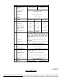
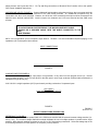
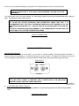
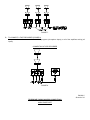
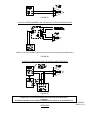
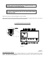
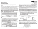
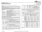
273 Branchport Avenue
Long Branch, N.J. 07740
(732) 222-6880
INSTALLATION INSTRUCTIONS
MODEL TPA-60-B/TPA-100-B
PAGING AMPLIFIERS
GENERAL APPLICATION INFORMATION:
Wheelock models TPA-60-B and TPA-100-B Paging Amplifiers are output rated at 60 watts RMS and 100 watts RMS
respectively.
These amplifiers afford a choice of five different inputs: two low impedance microphone inputs, one telephone paging
input, and two high impedance auxiliary inputs. Three input channels allow three of these inputs to be used actively at
one time: one microphone input, a choice of a telephone paging input or a second microphone input, and a choice of
either one of two auxiliary inputs. Note that the auxiliary input (i.e., background music, tone generator, etc) will
automatically be soft muted whenever a telephone page is generated or a microphone is used. After completion of the
page, the music will rapidly return to its original level.
A built-in limiter circuit (ALC) compensates for the varying voice levels and paging styles of the people who have access
to telephone paging or a microphone. The limiter maintains rated output without distortion.
The amplifiers feature individual input volume controls, as well as a master volume control, individual treble and bass
controls, a low-cut horn protect switch, two input selector switches, an illuminated power on switch, an internal ALC
(limiter) ON-OFF switch, an internal mute ON-OFF switch, a peak level indicator, and a line output jack.
Both models operate from 120 volts, 60Hz and have a power consumption of 180 watts (TPA-60-B) and 240 watts (TPA100-B). The units have a circuit breaker on the AC line input as well as a thermal breaker for overload protection on the
output. The AC circuit breaker is manually resettable. IN THE EVENT THE CIRCUIT BREAKER DOES NOT RESET,
HAVE THE TROUBLE INVESTIGATED BY AN AUTHORIZED SERVICE TECHNICIAN OR RETURN UNIT TO THE
FACTORY.
WARNING:
TO REDUCE THE RISK OF FIRE OR ELECTRIC SHOCK,
DO NOT EXPOSE THIS UNIT TO RAIN OR MOISTURE.
UNPACKING:
The amplifier was carefully checked before leaving the factory. Inspect shipping container and unit carefully for indication
of improper handling. If the unit has been damaged, make an immediate claim to the carrier.
MOUNTING INSTRUCTIONS:
The amplifier is provided with a set of universal mounting brackets to facilitate either rack or surface wall mounting.
Remove the 8 screws (4 on either side) holding the cover to the chassis. Choose the mounting required (rack or surface
wall), and insert screws through the universal mounting bracket and back into the cover/chassis holes as shown in
Figures 1 and 2.
CAUTION:
THESE DEVICES ARE NOT INTENDED FOR USE IN HAZARDOUS LOCATIONS AS
DEFINED BY THE NATIONAL ELECTRICAL CODE (NEC) AND BY THE NATIONAL FIRE
PROTECTION ASSOCIATION (NFPA).
P82423 C
Sheet 1 of 10
RACK MOUNTING
FIGURE 1.
SURFACE WALL MOUNTING
For surface mounting, be sure to use hardware suitable for the mounting surface.
FIGURE 2.
POWER AND GROUNDING:
The 120 VAC line cord has a three-prong plug which should be plugged into a three wire grounded electric outlet. It is
very important to maintain the amplifier ground for safe and trouble-free operation. If there is no grounded electric outlet,
connect a wire from the GND terminal on the OUTPUT terminal strip to a water or steam pipe.
P82423 C
Sheet 2 of 10
TECHNICAL SPECIFICATIONS:
#
PARAMETERS
1
POWER OUTPUT
@ 1 KHz
2
TOTAL HARMONIC
DISTORTION
3
OUTPUTS
4
LINE
OUTPUT
INPUTS
TPA-60-B
TPA-100-B
60 WATTS RMS
100 WATTS RMS
LESS THAN 2% THD
4 ohms, 8 ohms, 25V, 70V
150 ohm, 1.1VRMS
TELEPHONE
MIC 1/MIC 2
AUX 1/AUX 2
5
IMPEDANCE
600 ohm
600 ohm
47K ohms
6
SENSITIVITY
-20 dBm
1 mV
220 mV
7
FREQ. RESPONSE
300Hz - 4KHz
70Hz - 15KHz
70Hz - 15KHz
8
SIGNAL TO NOISE
RATIO
65dB
60dB
75dB
9
TYPE OF INPUT
XFMR
BALANCED
UNBALANCED
ISOLATED/BAL
OR UNBAL.
TEL/MIC 1, MIC 2, AUX 1/AUX 2, INPUT LEVELS,
BASS, TREBLE, MASTER VOLUME, TEL/MIC 1 AND
AUX 1/AUX 2 SELECTOR SWITCHES, POWER ON/OFF
SWITCH, LO-CUT SWITCH, ALC (LIMITER) ON-OFF
SWITCH (INTERNAL), AUX MUTE ON-OFF SWITCH
(INTERNAL).
10
CONTROLS
11
INDICATORS
AMBER OR RED NEON - POWER ON RED LED PEAK LEVEL
12
PROTECTION
13a
TREBLE CONTROL
AC LINE RESETTABLE CIRCUIT BREAKER AND
THERMAL OVERLOAD PROTECTION ON OUTPUT.
-10.5 dB TO +10.5 dB @ 12 KHz
13b
BASS CONTROL
14
15
LO-CUT SWITCH
AUTOMATIC LIMITER
FOR PAGING
16
AUTOMATIC MUTE
OPERATION
17
REGULATION
NO LOAD TO FULL LOAD OUTPUT LESS THAN 2 dB.
18
CONSUMPTION
180 WATTS MAX.
19
SIZE
20
WEIGHT
+10.5 dB TO -10.5 dB @ 100 Hz
-6 dB @ 250 Hz
+/-3 dB OUTPUT LEVEL MAINTAINED WITHOUT
CLIPPING, EVEN WHILE EXCEEDING RATED INPUT
LEVEL UP TO 20 dB.
OUTPUT LEVEL 1 WATT FOR 40 dB MUTING
280 WATTS MAX.
15"W X 11.25"D X 4.125"H
(38.1 X 28.6 X 10.1cm)
15lbs. (6.75Kg)
18lbs. (8.1Kg)
P82423 C
Sheet 3 of 10
INPUT CONNECTIONS
(FIGURES 3 & 4)
TELEPHONE PAGING INPUT (FIGURE 3): Connect telephone wires to the input screw terminals marked TIP and RING.
Set TEL/MIC 1 Switch (on front panel) to TEL position. For Tip and Ring connections to various types of telephone
paging access, see Figures 9A, B & C. For Tip and Ring connections to Wheelock Zone Controls, refer to the specific
zone control installation instructions.
MICROPHONE INPUTS (FIGURE 3): Connect balanced low-impedance microphone wires to the input screw terminals
marked LO-Z. The shield must be connected to the GND screw terminals. An unbalanced microphone may be
connected to the same screw terminals. However, one of the two LO-Z terminals for that input must be connected to the
adjacent screw terminal marked GND. Install a jumper wire, between one LO-Z screw terminal and the GND screw
terminal.
NOTE:
TO AVOID POSSIBLE INTERFERENCE, THE MICROPHONE INPUT CABLE
SHOULD BE A SHIELDED CABLE, WITH THE SHIELD CONNECTED TO THE
INPUT
GND TERMINAL.
MIC 2 is a low impedance (LO-Z) microphone input channel. TEL/MIC 1 is a switch selectable telephone paging, or low
impedance (LO-Z) microphone input channel.
INPUT CONNECTIONS
FIGURE 3.
AUXILIARY INPUTS (FIGURE 4):
To connect an FM tuner, CD player, tape player, tone generator, or any other line level program source (i.e., mic/line
mixer) to either the AUX 1 or AUX 2 input jacks on the back panel, use a single conductor shielded cable terminated in a
standard RCA type phono plug.
AUX 1/AUX 2 is a high impedance (HI-Z) input channel providing a selection of 2 separate inputs.
AUX 1/AUX 2
HIGH IMPEDANCE (HI-Z) INPUTS
FIGURE 4.
P82423 C
Sheet 4 of 10
OUTPUT CONNECTIONS (FIGURES 5&6)
REFERRING TO FIGURE 5:
Connect 2 output wires from the speaker load, to the COM screw terminal and the selected constant voltage terminal, (i.e.
25V or 70V). The constant voltage distribution method facilitates the use of multiple speakers in parallel with a single
amplifier. Note that each speaker must have its own 25V or 70V line-matching transformer. Select the wattage tap on the
line matching transformer of each speaker, for the power (volume) desired.
A 4 ohm or 8 ohm speaker load may be connected to the COM and either the 4 ohm or 8 ohm terminals.
NOTE:
THE WATTAGE RATING OF THE 4 OHM OR 8 OHM SPEAKER LOAD SHOULD NOT BE
EXCEEDED.
To minimize power loss in the system cabling, use a wire gauge suitable for the power being distributed and the length of
cable. See Wheelock product bulletin # 89-91.
NOTE:
TO ALLOW FOR FUTURE EXPANSION, AND DISTRIBUTION CABLE LINE LOSS, IT IS
RECOMMENDED THAT THE TOTAL SYSTEM WATTAGE SHOULD NOT EXCEED 85% OF THE
AMPLIFIER'S RATED OUTPUT (I.E. 51 WATTS FOR THE TPA-60 AND 85 WATTS FOR THE TPA100).
THE TOTAL SYSTEM WATTAGE REQUIREMENT IS THE SUMMATION OF THE WATTAGE TAP
SELECTIONS OF ALL SYSTEM SPEAKERS AND HORNS.
OUTPUT CONNECTIONS
FIGURE 5.
LINE OUTPUT (FIGURE 6):
The LINE OUTPUT jack on the back panel, can be used to cascade amplifiers (including amplified speakers, or
Wheelock PRM 150 preamplifiers), or connect (send signal to) a tape recorder. The signal on this output is a line level
mix of the amplifier's input channels. Use single conductor shielded cable with standard RCA type phone plugs.
LINE OUTPUT
FIGURE 6.
NOTE:
THE LINE OUTPUT SIGNAL IS CONSTANT AND IS UNAFFECTED BY THE AMPLIFIERS
MASTER VOLUME, BASS AND TREBLE CONTROLS.
P82423 C
Sheet 5 of 10
A.
CASCADING AMPLIFIERS (FIGURE 7):
TPA-60-B and TPA-100-B amplifiers can be cascaded to expand existing systems or to distribute large speaker
loads.
CASCADING AMPLIFIERS
FIGURE 7.
B.
TO CONNECT A TAPE RECORDER (FIGURE 8):
A tape recorder can be connected to record live programs (microphone inputs), or all of the amplifiers activity (all
inputs).
CONNECTING A TAPE RECORDER
FIGURE 8.
P82423 C
Sheet 6 of 10
TELEPHONE PAGING ACCESS CONNECTIONS
AUDIO PAGE PORT
FIGURE 9A.
CO LINE, CENTREX NUMBER LINE, OR ANALOG STATION EXTENSION PORT
(Refere to TPI-100 installation instructions for internal control settings and adjustments.)
FIGURE 9B.
UNUSED CO LINE/TRUNK PORT OR STAND ALONE TELEPHONE
FIGURE 9C.
CAUTION:
CONNECT ONLY TO PBX INCORPORATING ISOLATION FROM TELECOM NETWORK.
ATTENTION:
RACCORDER SUELEMENT A UNSYSTEME PBX INDEPENDANT/DU RESEAU DE TELECOMMUNICATION.
P82423 C
Sheet 7 of 10
OPERATION
FIGURE 10.
(Front panel controls, switches and indicators.)
NOTE:
ALL CONTROLS ROTATE CLOCKWISE TO INCREASE AND
COUNTERCLOCKWISE TO DECREASE.
EXTERNAL CONTROLS AND INDICATORS (FIGURE 10):
POWER ON-OFF SWITCH (ILLUMINATED):
The light inside the switch will illuminate when the AC cord is plugged into a 120 VAC source and the power switch is
pressed to the ON position. (Set at factory in OFF position.)
MASTER VOLUME CONTROL:
Adjusts the total output level of the amplifier without disturbing the individual settings of the microphone, telephone and
auxiliary input volume controls. (Set at factory in minimum position.)
TEL/MIC 1 INPUT VOLUME CONTROL:
Adjusts the volume of either the TEL (Telephone) paging or MIC 1 input. (Set at factory in the minimum position.)
AUX 1/AUX 2 INPUT VOLUME CONTROL:
Adjusts the volume of the AUX 1/AUX 2 inputs. (Set at factory in the minimum position.)
BASS AND TREBLE CONTROLS:
Adjusts bass and treble for optimum tonal balance of the output signal. The amplifier frequency response is flat with the
knob indicators pointing straight up (Dot #6). (Set at factory in Dot #6 position.)
TEL/MIC 1 SELECTOR SWITCH:
Switch to TEL position for telephone paging, or switch to MIC 1 position when using a microphone. (Set at factory in the
TEL position.)
AUX 1/AUX 2 SELECTOR SWITCH:
Switch to either AUX 1 or AUX 2 position, depending upon which of 2 program source inputs are utilized. (Set at factory
in AUX 1 position.)
HORN PROTECT/LO-CUT SWITCH:
This switch is located on the lower right hand side of the rear panel. Turn the switch ON whenever horns are used in the
system. This will protect the horn voice coils from damage by filtering out low frequencies inherent in some types of
music when played at high power settings. (Set at factory in OFF position.)
PEAK LEVEL INDICATOR:
Occassional flickering of the LED indicates momentary peak levels, and is a normal operating condition. Steady
illumination of the LED is an indication that an overdrive (clipping) condition may exist. If distortion is audible, then lower
the appropriate input volume control, and/or the master volume control.
P82423 C
Sheet 8 of 10
INTERNAL SWITCHES (FIGURE 11):
There are two internal switches. These are ALC (limiter) ON-OFF, and MUTE ON-OFF switches. They are accessed by
removing the amplifier cover.
NOTE:
FOR MOST PAGING AND BACKGROUND MUSIC SYSTEM APPLICATIONS, IT IS
NOT NECESSARY TO ACCESS THESE SWITCHES.
WARNING:
TO AVOID THE RISK OF ELECTRIC SHOCK, BE SURE THAT THE AMPLIFIERS AC
LINE CORD IS DISCONNECTED FROM THE AC POWER SOURCE BEFORE
REMOVING THE COVER.
Remove the 8 screws (4 on either side) holding the cover to the chassis.
When viewed from the top front of the amplifier, the switches are located on a 4 segment switch block, in the lower left
hand section of the power PC Board which is mounted to the chassis base.
ALC (LIMITER) AND MUTE ON-OFF SWITCHES
FIGURE 11.
P82423 C
Sheet 9 of 10
ALC (LIMITER) ON-OFF SWITCH:
For live program applications, (i.e., house of worship, auditoriums, etc.), it is often desirable to defeat the ALC (limiter)
function. This results in more "natural" (wider dynamic range) sound reproduction. Move switch #4 to the right (OFF)
position. (Set at factory in the ON position.)
MUTE ON-OFF SWITCH:
In certain applications (i.e., noise masking, tone signals, etc.), it is often desirable to defeat the auxiliary input mute
function. This results in the auxiliary input signal mixing (occurring simultaneously) with telephone paging, or microphone
input audio. Move switch #1 to the right (OFF) position. (Set at factory in the ON position.)
NOTE:
SWITCH POSITIONS #2 AND #3 ARE NOT USED. (SET AT FACTORY IN "ON"
POSITION.)
MAINTENANCE:
CAUTION:
THERE ARE NO USER-REPLACEABLE PARTS WITHIN THE UNIT.
HAVE ALL INTERNAL SERVICING DONE BY A QUALIFIED TECHNICIAN.
LIMITED WARRANTY:
Refer to Wheelock's Terms and Conditions of sale.
WARNING - ANY MATERIAL EXTRAPOLATED FROM THIS DOCUMENT OR FROM WHEELOCK MANUALS OR
OTHER DOCUMENTS DESCRIBING THE PRODUCT FOR USE IN PROMOTIONAL OR ADVERTISING CLAIMS, OR
FOR ANY OTHER USE, INCLUDING DESCRIPTION OF THE PRODUCT'S APPLICATION, OPERATION,
INSTALLATION AND TESTING IS USED AT THE SOLE RISK OF THE USER AND WHEELOCK WILL NOT HAVE
ANY LIABILITY FOR SUCH USE.
4/93
P82423 C
Sheet 10 of 10