1
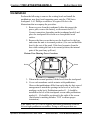
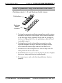
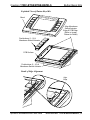
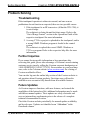
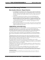
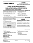
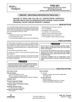
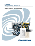
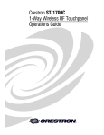
Crestron 1700C-BTNS-BEZELS and 1700C-BTNB-BEZELS Button Bezel Kits Operations & Installation Guide This document was prepared and written by the Technical Documentation department at: Crestron Electronics, Inc. 15 Volvo Drive Rockleigh, NJ 07647 1-888-CRESTRON All brand names, product names and trademarks are the property of their respective owners. ©2005 Crestron Electronics, Inc. Crestron 1700C-BTNS/BTNB-BEZELS Button Bezel Kits Contents Button Bezel Kits: 1700C-BTNS/BTNB-BEZELS 1 Introduction......................................................................................1 Installation........................................................................................3 Problem Solving...............................................................................6 Troubleshooting.....................................................................6 Further Inquiries ....................................................................6 Future Updates.......................................................................6 Return and Warranty Policies ..........................................................7 Merchandise Returns / Repair Service .........................7 CRESTRON Limited Warranty .....................................7 Operations & Installation Guide - DOC. 6321A Contents • i Crestron 1700C-BTNS/BTNB-BEZELS Button Bezel Kits Button Bezel Kits: 1700C-BTNS/BTNB-BEZELS Introduction Each Button Bezel Kit (refer to following table) includes a contemporary silver/black bezel, a total of ten pushbuttons—five for each side of the LCD screen—and two 5-button membrane switch actuators. The 1700C-BTNB-BEZELS kit is supplied with current 1700 Series touchpanels, but is also available for purchase for earlier 1700 Series units. The other kits are available for purchase for current or earlier 1700 Series touchpanels. Contact Crestron customer support for more information. Button Bezel Kit Details BUTTON COLOR ENGRAVABLE 1700C-BTNS-BEZELS Silver YES 1700C-BTNS-BEZELS-BLANK Silver NO 1700C-BTNB-BEZELS* Black YES 1700C-BTNB-BEZELS-BLANK Black NO KIT *Supplied with current 1700 Series Touchpanels Use the pushbuttons to access any frequently used commands with or without waking the display. Each button has a permanently fixed digital join number (refer to the illustration on the next page). The sequence of digital join numbers is (top to bottom) 1 through 5 on the left side and 6 through 10 on the right side. Operations & Installation Guide - DOC. 6321A Button Bezel Kits: 1700C-BTNS/BTNB-BEZELS • 1 Button Bezel Kits Crestron 1700C-BTNS/BTNB-BEZELS If your 1700 Series touchpanel has blank pushbuttons and you find that engraved pushbuttons are required, purchase the 1700C-BTNB (black) or the 1700C-BTNS (silver) Replacement Button pack. Engraving is included in the purchase of these items. Contact Crestron customer support for more information. NOTE: A user may not want the LCD screen to come on after a pushbutton is pressed when the unit is off. The Startup Preference option allows the user to select whether the touchpanel’s display comes on or stays off after a pushbutton is pressed. For more information, refer to the latest touchpanel Operations Guide. NOTE: A pushbutton can be used to flip a page (change a screen) on the touchpanel. Refer to the Crestron VisionTools Pro-e (VT Pro-e) help file (version 3.2.0.6 or later). Search the contents for ‘Hard Keys’ for direction to the appropriate “Project Properties” section. NOTE: To successfully send a pushbutton command when the touchpanel display is dark, the user may have to press the pushbutton twice with a minimum two-second interval between presses. This method is preferred because when a panel display is inactive, the user cannot discern whether the panel is in a standby or power down state. Furthermore, a single pushbutton press may not be transmitted depending on the state of the unit. For example, the DISPLAY ON FROM HARDKEY DISABLED command in startup preferences ensures that the panel display remains inactive. Pushbutton Layout and Join Number Assignment* 1 6 2 7 3 8 4 5 9 10 * Use the Crestron Engraver (version 2.3 or later) to submit custom engraving requests. The Engraver requires Crestron database (version 16.4.3 or later). 2 • Button Bezel Kits: 1700C-BTNS/BTNB-BEZELS Operations & Installation Guide - DOC. 6321A Crestron 1700C-BTNS/BTNB-BEZELS Button Bezel Kits Installation Perform the following to remove the existing bezel and install the pushbuttons, new bezel, and supporting parts onto the 1700 Series touchpanel. A #1 Phillips screwdriver is required. Refer to the illustrations that accompany the procedure. 1. Remove power from the touchpanel (either disconnect the power pack, remove the battery, or disconnect the RJ-11 Cresnet connection, depending on the touchpanel model) and place the touchpanel face down on a clean padded work surface. 2. Remove the four screws that secure the front bezel to the base and return the unit to its normal position. (Use care and hold the bezel to the rest of the panel. If the bezel separates from the base while rotating the unit to its normal position, the internal parts of the panel may spill out.) Bottom View Showing Screw Locations Screw Screw 3. When in the normal position, lift the bezel from the touchpanel. 4. Cover each membrane switch actuator with pushbuttons. Observe that pushbuttons differ from each other by their curved arrangement to match the openings in the bezel as well as the markings on the back. Pushbuttons marked 1 – 5 should be installed to the left of the touchpanel screen while pushbuttons marked 6 – 10 should be positioned to the right of the screen. (Each button’s marking includes ‘TOP’ to ensure proper orientation.) CAUTION: DO NOT cut or separate individual pushbuttons from the left and right pushbutton assemblies. Doing so will impair their use. Operations & Installation Guide - DOC. 6321A Button Bezel Kits: 1700C-BTNS/BTNB-BEZELS • 3 Button Bezel Kits Crestron 1700C-BTNS/BTNB-BEZELS NOTE: The pushbuttons fit snugly on the membrane switch actuators. Pushbuttons (right, 6 – 10) and Membrane Switch Actuator Pushbuttons Membrane Switch Actuators 5. Position the appropriate pushbuttons/membrane switch actuator assemblies on the sides of the display. Refer to the illustrations on the next page. Edge alignment ensures that the openings in the bezel will properly fit over the pushbuttons when the bezel is attached in step 6. 6. Position the new bezel (with pushbutton cutouts) over the exposed touchpanel. It may be necessary to lightly rock the bezel so that the buttons align with the holes in the bezel. 7. Hold the bezel to the touchpanel base and carefully rotate the entire panel onto its face once more. 8. Reinstall the four screws to secure the bezel to the base. Tighten the screws, being careful not to strip the threads. 9. Re-connect power and verify that the pushbuttons function properly. 4 • Button Bezel Kits: 1700C-BTNS/BTNB-BEZELS Operations & Installation Guide - DOC. 6321A Crestron 1700C-BTNS/BTNB-BEZELS Button Bezel Kits Exploded View of Button Bezel Kit Bezel Align Membrane Switch Actuator Edge & PCB Edge (Refer to Image Below for Detail) Pushbuttons (1 - 5) & Membrane Switch Actuator PCB Surface Pushbuttons (6 - 10) & Membrane Switch Actuator Detail of Edge Alignment Align Edge Operations & Installation Guide - DOC. 6321A Button Bezel Kits: 1700C-BTNS/BTNB-BEZELS • 5 Button Bezel Kits Crestron 1700C-BTNS/BTNB-BEZELS Problem Solving Troubleshooting If the touchpanel operation is otherwise normal, and one or more pushbuttons do not function as expected, there are two possible causes. 1. If the touchpanel is an RF transceiver (all but the TPS-1700), it is out of range. The solution is to bring the unit back into range. Refer to the “Out of Range Feature” section in the Operations Guide of the respective touchpanel for more information. 2. A wrong VT Pro-e project is uploaded to the touchpanel, and/or a wrong SIMPL Windows program is loaded to the control system. The solution is to upload the correct SIMPL Windows or VT Pro-e program. Refer to the respective help files for more information. Further Inquiries If you cannot locate specific information or have questions after reviewing this guide, please take advantage of Crestron's award winning customer service team by calling the Crestron corporate headquarters at 1-888-CRESTRON [1-888-273-7876]. For assistance in your local time zone, refer to the Crestron website (www.crestron.com) for a listing of Crestron worldwide offices. You can also log onto the online help section of the Crestron website to ask questions about Crestron products. First-time users will need to establish a user account to fully benefit from all available features. Future Updates As Crestron improves functions, adds new features, and extends the capabilities of the button bezel kit, additional information may be made available as manual updates. These updates are solely electronic and serve as intermediary supplements prior to the release of a complete technical documentation revision. Check the Crestron website periodically for manual update availability and its relevance. Updates are identified as an “Addendum” in the Download column. 6 • Button Bezel Kits: 1700C-BTNS/BTNB-BEZELS Operations & Installation Guide - DOC. 6321A Crestron 1700C-BTNS/BTNB-BEZELS Button Bezel Kits Return and Warranty Policies Merchandise Returns / Repair Service 1. No merchandise may be returned for credit, exchange, or service without prior authorization from CRESTRON. To obtain warranty service for CRESTRON products, contact the factory and request an RMA (Return Merchandise Authorization) number. Enclose a note specifying the nature of the problem, name and phone number of contact person, RMA number, and return address. 2. Products may be returned for credit, exchange, or service with a CRESTRON Return Merchandise Authorization (RMA) number. Authorized returns must be shipped freight prepaid to CRESTRON, 6 Volvo Drive, Rockleigh, N.J., or its authorized subsidiaries, with RMA number clearly marked on the outside of all cartons. Shipments arriving freight collect or without an RMA number shall be subject to refusal. CRESTRON reserves the right in its sole and absolute discretion to charge a 15% restocking fee, plus shipping costs, on any products returned with an RMA. 3. Return freight charges following repair of items under warranty shall be paid by CRESTRON, shipping by standard ground carrier. In the event repairs are found to be non-warranty, return freight costs shall be paid by the purchaser. CRESTRON Limited Warranty CRESTRON ELECTRONICS, Inc. warrants its products to be free from manufacturing defects in materials and workmanship under normal use for a period of three (3) years from the date of purchase from CRESTRON, with the following exceptions: disk drives and any other moving or rotating mechanical parts, pan/tilt heads and power supplies are covered for a period of one (1) year; touchscreen display and overlay components are covered for 90 days; batteries and incandescent lamps are not covered. This warranty extends to products purchased directly from CRESTRON or an authorized CRESTRON dealer. Purchasers should inquire of the dealer regarding the nature and extent of the dealer's warranty, if any. CRESTRON shall not be liable to honor the terms of this warranty if the product has been used in any application other than that for which it was intended, or if it has been subjected to misuse, accidental damage, modification, or improper installation procedures. Furthermore, this warranty does not cover any product that has had the serial number altered, defaced, or removed. This warranty shall be the sole and exclusive remedy to the original purchaser. In no event shall CRESTRON be liable for incidental or consequential damages of any kind (property or economic damages inclusive) arising from the sale or use of this equipment. CRESTRON is not liable for any claim made by a third party or made by the purchaser for a third party. CRESTRON shall, at its option, repair or replace any product found defective, without charge for parts or labor. Repaired or replaced equipment and parts supplied under this warranty shall be covered only by the unexpired portion of the warranty. Except as expressly set forth in this warranty, CRESTRON makes no other warranties, expressed or implied, nor authorizes any other party to offer any warranty, including any implied warranties of merchantability or fitness for a particular purpose. Any implied warranties that may be imposed by law are limited to the terms of this limited warranty. This warranty statement supercedes all previous warranties. Trademark Information All brand names, product names, and trademarks are the sole property of their respective owners. Windows is a registered trademark of Microsoft Corporation. Windows95/98/Me/XP and WindowsNT/2000 are trademarks of Microsoft Corporation. Operations & Installation Guide - DOC. 6321A Button Bezel Kits: 1700C-BTNS/BTNB-BEZELS • 7 Crestron Electronics, Inc. 15 Volvo Drive Rockleigh, NJ 07647 Tel: 888.CRESTRON Fax: 201.767.7576 www.crestron.com Operations & Installation Guide - DOC. 6321A 02.05 Specifications subject to change without notice.