1
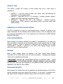
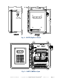
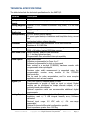
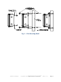
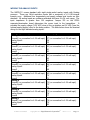
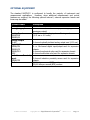
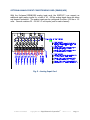
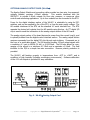
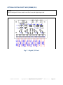
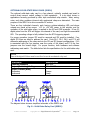
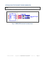
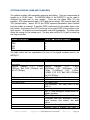
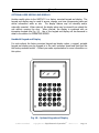
XARTU/5™ Manual Copyright© 2014 Eagle Research Corporation® REV 11.1.11 Page | 1 Table of Contents INTRODUCTION ................................................................................................ 1 OVERVIEW ...............................................................................................................3 RELIABILITY .............................................................................................................8 PRODUCT LINE........................................................................................................ 10 HAZARDOUS LOCATION CLASSIFICATIONS....................................................................... 13 FOUR-YEAR WARRANTY ............................................................................................ 14 RETURNS............................................................................................................... 16 ENCLOSURE SECURITY .............................................................................................. 19 TECHNICAL SPECIFICATIONS ........................................................................ 27 INSTALLATION................................................................................................ 42 UNPACKING............................................................................................................ 42 MOUNTING THE RTU................................................................................................ 48 POWER FOR THE RTU ............................................................................................... 52 COMMUNICATIONS ................................................................................................... 62 WIRING THE PULSE INPUTS ........................................................................................ 75 WIRING THE ANALOG INPUTS ..................................................................................... 85 WIRING THE DIGITAL I/O’S ....................................................................................... 96 OPTIONAL EQUIPMENT ................................................................................ 107 OPTIONAL 24VDC ANALOG SUPPLY ........................................................................... 114 DESCRIPTION ....................................................................................................... 117 SPECIFICATIONS .................................................................................................... 117 OPTIONAL ANALOG INPUT CONDITIONING CARD (EBM80/AI8) ........................................ 121 OPTIONAL ANALOG OUTPUT CARD (XA-AO) .............................................................. 125 XA-AO ANALOG OUTPUT SPECIFICATIONS................................................................. 134 WIRING THE ANALOG OUTPUT LOOPS ......................................................................... 141 OPTIONAL DIGITAL INPUT CARD (EBM80/DI4) ............................................................ 144 OPTIONAL RELAY CARD (EBM80/RC4) ...................................................................... 147 OPTIONAL SOLID-STATE RELAY CARD (SSRC4) ............................................................ 154 OPTIONAL INDUCTIVE PROXIMITY SENSOR (EBM80/IPS) ................................................ 162 OPTIONAL MODEMS (2400 AND 33,600 BPS) ............................................................. 166 OPTIONAL USER KEYPAD AND DISPLAY ........................................................................ 176 GROUNDING ................................................................................................. 183 OPERATING MODES ...................................................................................... 190 DISPLAY MODE ..................................................................................................... 194 ALARM MODE ....................................................................................................... 196 CONFIGURATION MODE ........................................................................................... 207 CALIBRATION MODE ............................................................................................... 238 MAINTENANCE .............................................................................................. 268 Remote I/O Manual Copyright© 2013 Eagle Research Corporation® Page | 2 ENCLOSURE MAINTENANCE ....................................................................................... 269 CALIBRATION ....................................................................................................... 275 SOFTWARE PACKAGES .................................................................................. 277 TALON DEVICE MANAGER AND TALON SCADA .............................................................. 277 Table of Illustrations FIG. 1 – XARTU/5 DOOR CLOSED ............................................................................... 21 FIG. 2 – XARTU/5 DOOR OPEN .................................................................................. 23 FIG. 3 – PROCESSOR/IOT BOARD DETAIL ......................................................................... 26 FIG. 4 – POLE MOUNTING DETAIL .................................................................................. 51 FIG. 5 – ANALOG INPUT CARD ..................................................................................... 124 FIG. 6 - XA-AO ANALOG OUTPUT CARD ...................................................................... 132 FIG. 7 – DIGITAL I/O CARD ........................................................................................ 146 FIG. 8 – SOLID-STATE RELAY CARD (SSRC4) ................................................................. 161 FIG. 9 - EBM80/IPS INDUCTIVE PROXIMITY SENSOR ........................................................ 165 FIG. 10 – OPTIONAL KEYPAD AND DISPLAY ..................................................................... 182 Remote I/O Manual Copyright© 2013 Eagle Research Corporation® Page | 3 INTRODUCTION NOTE All references in this manual to the XARTU/5 apply equally to the XARTU/10, except where noted. The primary difference between the two models is size – the XARTU/10 is larger, and typically contains the power supply and other supporting hardware for the system. Except where noted, this manual will refer to these units as ‘RTU’ or the ‘unit’. OVERVIEW The XARTU/5 Remote Terminal Unit is an intelligent, compact, rugged, and reliable industrial microprocessor-controlled computer designed for real-time remote data acquisition and control applications. It can execute multiple processes, including tasks such as complex math functions, control algorithms, etc., without host intervention. Flexibility, expandability, and reliability were the major factors in the XARTU/5 design philosophy. It is a balanced system, featuring flexible and expandable memory, I/O, power, and communications schemes including support for HEXASCII, MODBUS, and various other custom protocols upon request. A harsh environment tolerance is also one of the RTU’s strengths. The operating temperature can range from -40C to 70C, and the RTU comes in a fiberglass NEMA 4X enclosure. This allows the RTU to exist where the work must be done, eliminating costly signal conditioning or expensive long sensor runs. The operator interface is a two-line, 32-character, liquid crystal display, and 25-key keypad with nine user-definable function keys. This allows users to examine and/or change process data and diagnose problems at the remote site without a local host or terminal. The RTU, normally fed with a 9-30 VDC supply, employs a low-power CMOS design. An optional 120/240 VAC unit includes an uninterruptible power supply. Should it lose power, the RTU will sense the failure, automatically switch to battery power, and continue to operate at full capacity. Other power options include solar arrays and thermoelectric generators for sites without conventional power. RELIABILITY The RTU is ruggedly built to perform in a variety of industrial environments. Care is taken to maximize reliability by applying a urethane conformal coating to all circuit boards, utilizing a hermetically-sealed keypad and display, and providing NEMA 4X packaging. XARTU/5™ Manual Copyright© 2014 Eagle Research Corporation® REV 11.1.11 Page | 1 PRODUCT LINE The XARTU product line consists of three models that cover a wide range of applications. XARTU/1 - Low cost version (contact your factory sales representative for information on this popular model) XARTU/5 - Small box RTU (10” x 8” enclosure). Includes processor, display / keypad, and IOT60 expansion (termination) board. XARTU/10 - Big box RTU (18” x 16” enclosure). Includes processor, display/keypad, IOT60 expansion (termination) board, and power supply with battery backup. HAZARDOUS LOCATION CLASSIFICATIONS The RTU is designed to mount in a non-hazardous area. However, a system can be made intrinsically safe by installing intrinsic safety barriers in the non-hazardous area for equipment (transmitters, etc.) in the hazardous area (reference the NFPA National Electrical Code Book). FOUR-YEAR WARRANTY Eagle Research Corporation warrants the products it manufactures to be totally free from any defects in materials and workmanship under normal operation and use. Eagle Research agrees to repair or replace any instrument that is defective due to faulty workmanship or material, if returned to our factory with shipping charges prepaid, within four years of original purchase. RETURNS When a faulty product cannot be repaired in the field, contact Eagle Research Corporation for an RMA number and for return information. Packaging and shipping criteria will be established at that time. *IMPORTANT* REMOVE ANY REPLACEABLE BATTERY OR BATTERY PACK FROM ANY UNIT PRIOR TO ITS RETURN SHIPPING. DAMAGE CAUSED BY LOOSE BATTERIES WITHIN UNITS WILL NOT BE COVERED BY THE MANUFACTURER, AND MAY VOID ANY WARRANTY THE UNIT IS STILL UNDER ENCLOSURE SECURITY Quick-release door latches that may be padlocked are standard features of the RTU to prevent unwanted users from opening the enclosure. As an option, a magnetic doorajar switch may be installed to initiate an alarm when the unit’s door is opened. XARTU/5™ Manual Copyright© 2013 Eagle Research Corporation® REV 11.1.11 Page | 2 Fig. 1 – XARTU/5 Door Closed Fig. 2 – XARTU/5 Door Open XARTU/5™ Manual Copyright© 2013 Eagle Research Corporation® REV 11.1.11 Page | 3 Fig. 3 – Processor/IOT Board Detail XARTU/5™ Manual Copyright© 2013 Eagle Research Corporation® REV 11.1.11 Page | 4 TECHNICAL SPECIFICATIONS The table below lists the technical specifications for the XARTU/5. Features Input Power 5(Vcc)Volt Supply Analog Supplies Power Monitoring Backup Battery Processor Memory Real-time Clock Pulse Inputs Digital I/O Analog Inputs Description 9-30 VDC 5 VDC @ 500mA max, high efficiency switching supply Optional 24 VDC isolated transmitter loop power, 375 mA max output Supply voltage monitoring through a/d with low supply voltage interrupt 3.6 VDC lithium backup battery 10 years typical backup of database and time/date during normal use low backup battery voltage detection Phillips P51XAS3 high performance 16-bit microcontroller Executes at 22.1184 MHz 512K x 16 remotely-programmable FLASH program memory 512K x 16 battery-backed RAM data memory Battery-backed, quartz crystal controlled +/- 1 sec/day typical accuracy Programmable time scheduled interrupt capability Eight pulse inputs Software programmable for Form A or C Software programmable for high or low speed Each counter is a six-digit (0-999999) hardware counter with programmable interrupt support Precision pulse width measurement is supported using the programmable counter array module in the P51XAS3 microcontroller Can be used for pulse accumulation, and for more complex applications such as card readers Thirty-two memory-mapped digital i/o lines Programmable in groups of eight as input or output. Digital outputs can be configured as simple discrete outputs, or as precisely-timed pulse outputs. Optional expansion cards can accommodate additional digital requirements. Sixteen-channel, single-ended with floating common. 16-bit resolution, max +/- 3 LSB integral linearity error; Software calibrated Nominal input range 0-5 VDC with +/- 4% over-range measurable Optional 8-channel differential configuration possible Input impedance greater than 100 Meg XARTU/5™ Manual Copyright© 2013 Eagle Research Corporation® REV 11.1.11 Page | 5 Communication s Status LED’s Expansion Capability Optional expansion cards can accommodate additional analog requirements. Two RS-232 ports with RX, TX, RTS, CTS, and communication switch signals Configurable speed up to 115,200 baud Directly interfaces to modems, radios, etc. Communication protocols selectable on a per port basis Eagle HexASCII, Modbus, Teledyne/Geotech, Valmet, BSAP Two LED’s; one red and one green for visual status information Software controllable for various function indications Two 50-position connectors provide access to all I/O lines Processor board plugs directly into compatible family termination boards Additional connectors provide redundant termination points to allow for configuration flexibility Two 10-position connectors allow for expansion over I2C communications bus Two 6-position connectors for RS-232 One 3-position connector for input power XARTU/5™ Manual Copyright© 2013 Eagle Research Corporation® REV 11.1.11 Page | 6 INSTALLATION UNPACKING 1. Thoroughly examine the box to verify it was not damaged in shipping. If you find damage, immediately file a claim with the shipper, as the manufacturer cannot be held responsible for items damaged in transportation and accepted by the customer. 2. Carefully unpack the RTU from the shipping container. Verify that the box contains every item listed on the shipping order. *CAUTION* This unit contains certain electronic components that are sensitive to electrostatic discharge (ESD); therefore, proper precautions should be taken during maintenance operations. It is recommended that the operator first touch the MS connector (RS-232C port) on the side of the unit to dissipate any accumulated static charge. Additional precautions may be taken in order to minimize the possibility of ESD, including the use of a grounding wrist strap (i.e., 3M part number 2214). If these precautions are not taken, and the unit is subjected to severe ESD, it may revert to its default state. However, the unit will not exhibit any loss of data or degradation of performance. 3. Open the front door by loosening the upper and lower right hand corner screws or quick release latches of the enclosure and swinging the door out. 4. Examine the label on the inside top of the enclosure. It indicates the model and serial number of the unit. MOUNTING THE RTU The RTU mounts directly on a wall or, optionally, on a pipe. Mounting feet are provided for wall mounting, and plates with U-bolts are provided for pole mounting. Two-inch rigid pipe or conduit is required for pole mounting. It is recommended the pipe be placed 18 to 24 inches in the ground in a six-inch wide sackrete/concrete-filled hole. The length of the 2-inch mounting pipe or conduit will vary according to the site, but typical installations place the RTU at about eye level for ease of operation. XARTU/5™ Manual Copyright© 2013 Eagle Research Corporation® REV 11.1.11 Page | 7 Fig. 4 – Pole Mounting Detail XARTU/5™ Manual Copyright© 2013 Eagle Research Corporation® REV 11.1.11 Page | 8 POWER FOR THE RTU Eagle Research provides an XA-Series UPS (uninterruptible power supply) and SPS (solar power supply) for unit power to the RTU. The RTU typically operates on an AC voltage power system with a 2.2 amp hour backup battery. Solar power systems with battery backup can be designed for any application where AC is not readily available. The sizing of solar systems depends on the geographic location, degree of sun exposure, equipment power consumption, and site obstructions. If the main supply fails, the unit will run on the system battery. If this should fail, an on-board backup battery will power the unit's memory and real time clock. The on-board backup battery can maintain history data for up to ten years. When the on-board backup power is used, the RTU discontinues normal operation until the main power source is restored. To power the unit with an XA-Series UPS: [NOTE: The XARTU/5 is supplied with a remote, external power system (XAUPS or XASPS) where the XARTU/10 has the power system mounted internally] 1. Disconnect and lock out the main AC source to be connected to the power supply before performing any wiring (circuit breaker, disconnect switch, etc.). 2. With the main AC source disconnected and locked out, connect the AC line to the L1 (hot), L2 (neutral), and GND terminals of the PWR60 board. ~WARNING~ The operating voltage range for the XARTU/5 is 9-30VDC. Do NOT exceed recommended input voltage of 30VDC. 3. Connect the positive and negative voltage signal wires to terminals 53 (V+) and 54 (GND) in the RTU. On the PWR60 power supply board, connect the wire from the Output (+12V) terminal, to terminal 53 on the IOT60 board in the RTU, and the Output (–) terminal, to terminal 54. Connect the Output LB (low battery) and the PFS (power fail status) wires to two of the digital inputs in the RTU for low battery and AC power failure alarms respectively. 4. Reconnect the main AC power source. 5. Toggle the SW1 switch on the IOT60 board to the ON (up) position to apply power to the RTU. 6. When power is first applied, the display will briefly show the program version, followed by the first assigned label. The green status LED comes on and starts to flash. Each LED flash indicates the time it takes the processor to complete one scan of the database. XARTU/5™ Manual Copyright© 2013 Eagle Research Corporation® REV 11.1.11 Page | 9 7. You can also change parameter values, and view or acknowledge active alarms using the display and keypad. See information on these functions starting on pages 21. COMMUNICATIONS To communicate with the XARTU/5, the Site ID in the device must be the same as the Site ID entered in the software package. The Site ID is a unique identification number (1 to 65,535), which allows the software packages to communicate with the RTU. The default Site ID number is 1. Site ID Changer (Meter Reader utility), Virtual Keypad option, or Talon can be used to enter a number other than the default. Refer to the respective software User’s Manual for additional information on these and other functions. The display and keypad can also be used to change the Site ID from its default value. RS-232C Serial Communications (up to 115,200 Baud) In its standard configuration, the XARTU/5 is equipped with two RS-232C serial ports with RX, TX, CTS, RTS, communication switch, and ground signal lines. The serial ports can be configured for speeds up to 115,200 baud. The baud rate can be adjusted using the EEPROM editor in the RTU. The serial ports can directly interface to modems, radios, etc., allowing an operator to configure and collect data with an industry-standard (IBM , Compaq , etc.) portable computer (Talon software is required for this function). Communication protocols are selectable on a per port basis (Eagle HexASCII, Modbus, Teledyne/Geotech, Valmet or BSAP). When communicating with the RTU, the first or second character field on the display will flash representing port #0 or port #1. An optional RS-232C serial cable is required for direct communications. The J3 and J4 6position MTA connectors on the Processor board provide connection for the two RS-232 ports (por#0 and port #1 respectively). The table below shows the terminal wiring for the two serial ports. NOTE Port 0 is shared with the optional modem. XARTU/5™ Manual Copyright© 2013 Eagle Research Corporation® REV 11.1.11 Page | 10 RS-232 Ports Description Port 0 RX0 (receive) TX0 (transmit) CTS0 (clear to send) RTS0 (request to send) CMSW0 (communication switch) GND0 (ground) Port 1 RX1 (receive) TX1 (transmit) CTS1 (clear to send) RTS1 (request to send) CMSW1 (communication switch) GND1 (ground) XARTU/5™ Manual XARTU/5 Terminal Location 17 18 19 20 21 22 23 24 25 26 27 28 Copyright© 2013 Eagle Research Corporation® REV 11.1.11 Page | 11 WIRING THE PULSE INPUTS The XARTU/5 comes standard with eight pulse inputs that are software programmable for Form A or C, and high speed or low speed. These inputs can be used as simple pulse counters, or in more demanding applications such as card readers. The table below shows the terminal wiring for the pulse inputs. Pulse Input Description Pulse 0 Low0 Pulse0 High0 (no connection for Form Pulse 1 Low1 Pulse1 High1 (no connection for Form Pulse 2 Low2 Pulse2 High2 (no connection for Form Pulse 3 Low3 Pulse3 High3 (no connection for Form Pulse 4 Low4 Pulse4 High4 (no connection for Form Pulse 5 Low5 Pulse5 High5 (no connection for Form Pulse 6 Low6 Pulse6 High6 (no connection for Form Pulse 7 Low7 Pulse7 High7 (no connection for Form XARTU/5™ Manual XARTU/5 Terminal Location A) 29 30 31 (no connection for Form A) A) 32 33 34 (no connection for Form A) A) 35 36 37 (no connection for Form A) A) 38 39 40 (no connection for Form A) A) 41 42 43 (no connection for Form A) A) 44 45 46 (no connection for Form A) A) 47 48 49 (no connection for Form A) A) 50 51 52 (no connection for Form A) Copyright© 2013 Eagle Research Corporation® REV 11.1.11 Page | 12 WIRING THE ANALOG INPUTS The XARTU/5 comes standard with eight single-ended analog inputs with floating common. These are 16-bit resolution inputs with a maximum of ±3 LSB integral linearity error. Additional box temperature and supply voltage level inputs are also standard. All analog inputs are software calibrated and have a ±4% over-range. The input impedance is greater than 100 megohms. Jumper JP5 on the IOT60 expansion/termination board determines the power input to the transmitters. It provides the supply voltage (9-30 VDC) when in the up position and 24 VDC (from the optional analog supply) when in the down position. The table below shows the terminal wiring for the eight standard analog inputs. Analog Input Description Analog 0 Ground0 (no connection for 4-20 Analog Input0 Power0 Analog 1 Ground1 (no connection for 4-20 Analog Input1 Power1 Analog 2 Ground2 (no connection for 4-20 Analog Input2 Power2 Analog 3 Ground3 (no connection for 4-20 Analog Input3 Power3 Analog 4 Ground4 (no connection for 4-20 Analog Input4 Power4 Analog 5 Ground5 (no connection for 4-20 Analog Input5 Power5 Analog 6 Ground6 (no connection for 4-20 Analog Input6 Power6 Analog 7 Ground7 (no connection for 4-20 Analog Input7 Power7 XARTU/5™ Manual XARTU/5 Terminal Location mA input) 57 (no connection for 4-20 mA input) 58 59 mA input) 60 (no connection for 4-20 mA input) 61 62 mA input) 63 (no connection for 4-20 mA input) 64 65 mA input) 66 (no connection for 4-20 mA input) 67 68 mA input) 69 (no connection for 4-20 mA input) 70 71 mA input) 72 (no connection for 4-20 mA input) 73 74 mA input) 75 (no connection for 4-20 mA input) 76 77 mA input) 78 (no connection for 4-20 mA input) 79 80 Copyright© 2013 Eagle Research Corporation® REV 11.1.11 Page | 13 WIRING THE DIGITAL I/O’S The XARTU/5 comes standard with sixteen memory-mapped digital I/O lines. They are programmable, in groups of eight, as inputs or outputs. Digital outputs can be configured as simple discrete outputs, or as precisely timed pulse outputs. Digital I/O Description PortA0 PortA1 PortA2 PortA3 PortA4 PortA5 PortA6 PortA7 PortB0 PortB1 PortB2 PortB3 PortB4 PortB5 PortB6 PortB7 XARTU/5 Terminal Location 1 2 3 4 5 6 7 8 9 10 11 12 13 14 15 16 The four (4) opto module slots (opto1, opto2, opto3, and opto4) on the IOT60 board can be used as inputs or outputs. Jumpers JP1, JP2, JP3, and JP4 determine the port configuration for the opto module slots. In the up position, JP1, JP2, JP3, and JP4 are configured for Ports A0, A1, A2, and A3 respectively. In the down position, JP1, JP2, JP3, and JP4 are configured for Ports B0, B1, B2, and B3 respectively. LED1, LED2, LED3, and LED4 are signal indications for the four opto module slots. The table below shows the terminal wiring for the four opto module slots. Opto Module Slots Description Opto 1 HL1-1 (-) HL1-2 (+) Opto 2 HL2-1 (-) HL2-2 (+) Opto 3 HL3-1 (-) HL3-2 (+) Opto 4 HL4-1 (-) HL4-2 (+) XARTU/5™ Manual XARTU/5 Terminal Location 83 84 87 88 81 82 85 86 Copyright© 2013 Eagle Research Corporation® REV 11.1.11 Page | 14 OPTIONAL EQUIPMENT The standard XARTU/5 is configured to handle the majority of instrument and measurement applications. However, when additional measurement and control features are required, the following optional internal / external expansion boards and items may be added. Optional Items Backup Battery Analog Supply Analog Input EBM80/AI8 EBM800/AI Analog Output XA-AO Digital I/O EBM80/DI4 EBM800/DI EBM80/RC4 SSRC Inductive Proximity Input EBM80/IPS Modem XARTU/5™ Manual Description 7-85 AH battery backup for 12 and 24 VDC 24 VDC isolated transmitter loop power supply (375 mA maximum output) 8- or 16-channel analog input conditioning cards (4-20 ma or 0-5 volts) 2-channel optically isolated analog output card (4-20 ma) 4- or 16-channel digital input/output card for expansion chassis 4-channel mechanical relay card for expansion chassis 4-channel solid state relay card for expansion chassis 2-channel inductive proximity sensor card for expansion chassis 2400 bits per second (BPS) modem 33,600 bits per second (BPS) modem Copyright© 2013 Eagle Research Corporation® REV 11.1.11 Page | 15 OPTIONAL 24VDC ANALOG SUPPLY The optional 24 VDC isolated transmitter loop power supply provides power for all 16 analog input channels. The table below shows the terminal wiring for the 24 VDC isolated output. Isolated 24 Volts (External use) 24VISO GND XARTU/5 Terminal Location 55 56 The table below lists the specifications for the optional 24 VDC supply used in the RTU. Description Environmental Operating temperature Humidity EMI RFI Shielding Electrical Specifications Input Efficiency Output Short Circuit Protection Overvoltage Protection I/O Isolation Special Features XARTU/5™ Manual Specifications -40ºC to + 80ºC 5% to 95% (Non-condensing) Six-sided 9 to 30 VDC 83% typical 24 VDC @ 375 mA Continuous Power Cycle Zener clamp all outputs 1500 VDC Meets EN55022A for conducted noise Copyright© 2013 Eagle Research Corporation® REV 11.1.11 Page | 16 OPTIONAL ANALOG INPUT CONDITIONING CARD (EBM80/AI8) With the 8-channel EBM80/AI8 analog input card, the XARTU/5 can support an additional eight analog inputs for a total of 16. All the analog inputs have gas tubes and transorb protection. The analog inputs can be configured for either 4-20 ma or 1-5 volts. Remove resistors R1 – R8 for 1-5 volt inputs (one for each channel). Fig. 5 – Analog Input Card Analog Input Card (EBM80/AI8) XARTU/5™ Manual Copyright© 2013 Eagle Research Corporation® REV 11.1.11 Page | 17 OPTIONAL ANALOG OUTPUT CARD (XA-AO) The Analog Output Module and connecting cable provides two two-wire, loop-powered, optically isolated, precision 4-20mA outputs. This module interfaces with the XARTU/5 to provide 4-20mA outputs for flow rate, pressure, or numerous other controls and monitoring applications. Up to four modules can be connected to the RTU. Power for the digital interface section of the XA-AO is selectable by using its DIPswitches, and can be supplied by Vcc of the RTU, or from the main supply voltage. The AO module interfaces to the RTU via the standard I2C serial interface bus. The RTU requests the desired mA outputs from the AO module using this bus. An I2C digital I/O chip is used to send the information to the analog output section of the AO board. The analog output section of the board derives its power from the current loop(s), and is optically isolated from the digital control interface section. The analog output section receives commands from the digital I/O chip through opto-isolators. Commands are in the form of a serial data stream. The AO module provides 4-20mA output signals with a resolution of 1 part in 65536 (16 bit), or 0.00024mA. The D/A also allows for overranging of the output to a minimum of 3.5mA and a maximum of 24mA. The field interface to the D/A is a simple two-wire connection. Reverse polarity protection is provided. The XA-AO will function properly in temperatures from –40ºF to +160ºF, and in conditions of high humidity (including condensing environments). Software calibration of the 4-20 mA outputs is provided for easy calibration. Fig. 6 - XA-AO Analog Output Card XARTU/5™ Manual Copyright© 2013 Eagle Research Corporation® REV 11.1.11 Page | 18 XA-AO ANALOG OUTPUT SPECIFICATIONS Description Environmental Operating Temperature Operating Humidity Electrical Isolation Specifications -40°F to +160°F 0 to 100% 500 VDC or AC RMS (sine wave) between digital interface and 4-20 mA loop Current Loop Output Maximum Output Current Minimum Output Current Maximum Supply Voltage Minimum Supply Voltage Resolution Full Scale %Error (software calibrated at 4 and 20 mA and tested at room temperature) Temperature Drift Error caused by RFI Digital Control Interface Vcc Powered Input Current Vin Powered Input Current Communications Interface Physical Width with mounting tabs Width without mounting tabs Height Depth 24mA 3.5mA 50V 8V 16 bits, 0.00024 mA ±0.01% max ±0.00044 mA/°F max <1% of span shift with 2.8W 150MHz applied at 1.7’ 10 uA max in idle mode; 15 mA max during communications 30 uA higher than with Vcc power (typical) I2C as described for the Phillips PCF8575 digital I/O chip 4.75” 3.78” 2.14” 0.69” WIRING THE ANALOG OUTPUT LOOPS The external wiring to the AO module is very simple. A ribbon cable connects the AO module to the IOT60 expansion/termination board. Commands are sent to the module via the cable by the RTU. The 4-20mA current loop is a simple two-wire connection. +24 VDC loop power is connected to the “+” terminal (pos. 1), and the “-”, or return terminal (pos. 2), is connected to the field instrument to which the 4-20 mA signal is being sent. XARTU/5™ Manual Copyright© 2013 Eagle Research Corporation® REV 11.1.11 Page | 19 OPTIONAL DIGITAL INPUT CARD (EBM80/DI4) NOTE Four of the digital I/O lines must be sacrificed to use the digital input card. Fig. 7 – Digital I/O Card Digital I/O card (EBM80/DI4) XARTU/5™ Manual Copyright© 2013 Eagle Research Corporation® REV 11.1.11 Page | 20 OPTIONAL RELAY CARD (EBM80/RC4) The optional mechanical relay card has four channels for generating pulse outputs. The outputs are fused at 5 amps, and an individual LED provides the status of each output. Jumper JP1 determines whether the +12 VDC power source for the relay coil is internal or external. The default setting sources the relay coil externally. Jumpers JP2, JP3, JP4, and JP5, one for each relay, determine whether the relay coils are energized on a low or high logic state from the RTU. The default setting is for low logic state. Ports P4.0, P5.0, P6.0, and P7.0 determine the addressing of the relay outputs in sets of four. For proper function, both hardware and software addressing must match. The table below lists the specifications for the mechanical relay card. NOTE Four of the digital I/O lines must be sacrificed to use the mechanical relay card. Description Electrical Isolation Dielectric Strength Surge Strength Specifications 750 VAC (between open contacts) 2000 VAC (between coil and contacts) 4000 V standard, 6000 V high (at 1.2x50us standard surge wave) Output (Switching) 30 VDC / 250 VAC, Resistive Voltage Output Current (max) Momentary 5 A (no), 3 A (nc) Continuous 5A XARTU/5™ Manual Copyright© 2013 Eagle Research Corporation® REV 11.1.11 Page | 21 OPTIONAL SOLID-STATE RELAY CARD (SSRC4) The optional solid-state relay card is a four-channel, optically coupled card used to control direct current output voltage to field equipment. It is an ideal choice in applications formerly governed by older style mechanical relay circuits. Wear, arcing, noise, and other problems inherent with mechanical relays are eliminated. The main purpose of the SSRC4 is to drive reversible DC motors. There are four individual channels, each having a status-indicating LED, and whose outputs are fused at two amps. +12 to +24 VDC power to the outputs, and for operation of the solid state relays, is applied to the VS and COM terminals. A low (0) digital pulse from the RTU will trigger one channel of the card, and light the associated LED. The operating voltage is fully isolated from the RTU triggering signals. For proper operation, jumper JP3 must be removed and JP4 must be installed. Four digital I/O lines are used to address the card. Ports P4.0, P5.0, P6.0, and P7.0 will determine addressing of the relay card via the JP1 and JP2 jumper configurations. P4.0 is associated with the four jumpers near the center of the board, and P7.0 the four jumpers near the board’s edge. For proper function, both hardware and software addressing must match. The table below lists the specifications for the solid-state relay card. NOTE Four of the digital I/O lines must be sacrificed to use the mechanical relay card. Description Electrical Isolation Output (Switching) Voltage Output Current (max) Momentary Continuous Specifications 5000 VAC 12 to 24 VDC 2 amps 1 amp The diagram below shows a simplified schematic of the SSRC4 card Fig. 8 – Solid-State Relay Card (SSRC4) XARTU/5™ Manual Copyright© 2013 Eagle Research Corporation® REV 11.1.11 Page | 22 OPTIONAL INDUCTIVE PROXIMITY SENSOR (EBM80/IPS) NOTE Four of the digital I/O lines must be sacrificed to use the inductive proximity sensor card. Fig. 9 - EBM80/IPS Inductive Proximity Sensor XARTU/5™ Manual Copyright© 2013 Eagle Research Corporation® REV 11.1.11 Page | 23 OPTIONAL MODEMS (2400 AND 33,600 BPS) The optional modems offer automatic answering and dialing. They can communicate at speeds up to 33,600 baud. The EEPROM editor in the XARTU/5 can be used to configure the baud rate for your modem. There are five status LEDs: RI (ring indicator), DTR (data terminal ready), DCD (data carrier detect), RXD (receive data) and TXD (transmit data). Jumper JP6 on the IOT60 expansion/termination board controls how the modem is powered. It supplies 5VDC continuously to the modem when in the left position, and requires Port D7 to be turned on to supply 5VDC to the modem in the right position. All modems are interchangeable and field upgradeable. The table below shows the wiring for the modem port. You may also use the RJ-11 jack for direct tip and ring connection. Modem Description TIP RING GND GND XARTU/5 Terminal Location 89 90 91 92 The table below lists the specifications for two of the typical modems used in the XARTU/5. 2400 Baud FCC Part 68 approved and DOC approvable Supports standard CCITT V.22bis (2400bps), Bell 212A (1200bps), and Bell 103 (300bps) AT Command structure with extensions 1000 VAC isolation barrier Non-volatile RAM XARTU/5™ Manual 33,600 Baud FCC Part 68 approved and DOC approvable Supports standard CCITT V.34bis (33,600bps), V.34 (28,800bps), V.FC, V.32bis (14,400bps), V.32, V.22bis, V.22A/B, V.23, V.21, Bell 212A (1200bps) and 103 (300bps) AT Command structure with extensions 1000 VAC isolation Non-volatile RAM Error correcting – V.42 LAMP, MNP 2-4 and MNP 10 Data compression – V4.2bis and MNP 5 MNP 10 Data throughput enhancement for cellular operation DTE interface with speeds up to 11.5kbps Automated baud rate adaptability utilizing speed sensing, flow control, and data buffers Data modem throughput up to 115.2kbps Supports Send & Receive Fax Class 1, Copyright© 2013 Eagle Research Corporation® REV 11.1.11 Page | 24 Group 3 OPTIONAL USER KEYPAD AND DISPLAY Another useful option to the XARTU/5 is a factory mounted keypad and display. The keypad and display may be used to access, change, and view programming data and stored information while on site. The display feature may be internally and/or externally mounted. When external, the display alone may be viewed from outside the unit without opening the door. When internal, the display is combined with an interactive keypad (see Fig. 10). Use of the keypad and display will be discussed in detail in the section on OPERATING MODES. Handheld Keypad and Display For units without the factory mounted keypad and display option, a rugged, portable keypad and display may be plugged in to the unit’s processor board and used just like the factory-mounted model. Contact your sales representative for more information on this option. Fig. 10 – Optional Keypad and Display XARTU/5™ Manual Copyright© 2013 Eagle Research Corporation® REV 11.1.11 Page | 25 GROUNDING Because of the potential for equipment damage and injury to personnel, certain practices should, and often must, be observed when installing RTU systems. Of these practices, proper grounding is possibly the single most important. This section was included to point out general rules and practices, and NOT to supersede those defined in the National Electrical Code (NEC) published by the National Fire Protection Association (NFPA), nor the Classification of Gas Utility Areas for Electrical Installations booklet published by the American Gas Association (AGA). A sound understanding of Federal, State, and Local laws is fundamental to proper and legal installation work. Eagle Research Corporation makes no warranties or guarantees on the effectiveness or safety of any technique or suggestion here described. All RTU, electronic utility interface, and gas meter equipment should be kept at the same ground potential so that unexpected voltages anywhere on the system are quickly shunted away to earth. This calls for a common ground rod (or "bed" of grounding materials) to which is securely tied all equipment chassis, metal cabinets, and intrinsic safety ground brackets. For equipment chassis and metal cabinets, a solid copper ground wire or ground strapping of an approved size and type is recommended to tie this equipment to the rod(s). For Intrinsic Safety systems, it is recommended that two #12 AWG wires be run in parallel from individual ground terminals on each I.S. ground frame. Where more than one rod is used, as when equipment is separated by some distance, all rods should be bonded together with copper in an approved manner. REFERENCES * National Electrical Code Article 250 - Grounding Articles 500 & 501 - Hazardous (Classified) Locations Article 504 - Intrinsically Safe Systems * The IAEI Soares' Book on Grounding * PolyPhaser Corp.'98 catalog of Lightning/EMP & Grounding Solution XARTU/5™ Manual Copyright© 2013 Eagle Research Corporation® REV 11.1.11 Page | 26 OPERATING MODES The XARTU/5 operates in any of the following four standard modes: Display Alarm Configuration Calibration To access any operating mode, press the keypad key that corresponds to the mode you want: conf alrm cal esc for configuration mode for alarm mode for calibration mode to return to a previous mode from any other mode DISPLAY MODE In display mode only limited parameters with assigned labels and function keys can be viewed. The and arrow keys will allow you to scroll through the display parameter list. You may use the jump key to directly view any of the assigned labels; press jump, then enter the label number XXX, followed by pressing ent. You can use the function keys (F0 - F9) to view previously assigned parameters. Talon software can be used to assign function keys and labels to any parameter. ALARM MODE The RTU can be configured to activate an alarm when certain conditions are met, or when user defined limits are exceeded. Active alarm messages can be configured for display on the RTU's display. The unit can also automatically call a host computer running Talon software to report an alarm. A history log is kept in the RTU on each alarm condition, consisting of the following: Current value Type of alarm (high, low etc.) Setpoint value (alarm limit) Time of alarm Date of alarm Time out of alarm Date out of alarm Extreme value alarm XARTU/5™ Manual Copyright© 2013 Eagle Research Corporation® REV 11.1.11 Page | 27 The RTU can be configured to monitor and alarm on any condition including, but not limited to, the following: First Time Power AC Power Failure Low Supply Volts High and Low Flow Rate High and Low Pressure High and Low Differential Pressure High and Low Temperature Current Day Flow (Transportation Limit) Low Voltage Shutdown Box intrusion Liquid levels Valve status NOTE Additional hardware equipment and configuration may be required for some alarm monitoring. Viewing and Clearing Alarms from the keypad To enter alarm mode, press the alrm key. In alarm mode, you can view and acknowledge any alarm. If alarms are active, the unit will display the first alarm message. If there are more alarms, you can view them by pressing the key. Repeatedly pressing the key cycles through the active alarm list. Alarms can be locally acknowledged at the RTU by pressing the ent key while a particular alarm message is displayed or by polling with Talon software. Unless the parameter's limits are violated again, the unit will not include acknowledged alarms in its list the next time the user enters alarm mode. To exit alarm mode without acknowledging the alarm, simply press the esc key. CONFIGURATION MODE To enter configuration mode, press the conf key. If the configuration mode is password protected, the RTU will display ENTER PASSWORD?. Only a valid password entry would then be given access to this mode. Configuration mode allows you to set up the RTU's initial configuration, change any of the operating parameter values, set alarm conditions and limits, or assign function keys to a parameter. While in the configuration mode, the RTU continues to operate normally; it continues to sample live pressure and temperature values, calculate corrected volume, and collect historical data. XARTU/5™ Manual Copyright© 2013 Eagle Research Corporation® REV 11.1.11 Page | 28 Viewing Parameters In configuration mode, any parameter value may be viewed. One method is to use the Jump key to directly view database items. Press Jump and then enter the address of the parameter followed by pressing the ent key. The top line on the display is the software address, and the bottom line is the value. Function key assignments are still valid, so often-viewed parameters may be accessed in this manner. The right and left arrow keys ) allow horizontal movement between processes, and the up and down arrow keys allow moving vertically within a process. Pressing Jump followed by the right arrow key ( will display the same item number in the next section. Likewise, pressing Jump followed by the up arrow key will display the same item number in the previous section. Jumping to assigned labels is also supported as described in Display Mode. Editing Parameters 1. Enter configuration mode by pressing the conf key (use the password if required). 2. Display the desired parameter. Press the jump key, followed by the address of the parameter. The function keys can also be used to view assigned parameters. 3. With the desired parameter displayed, press the edit key. (The unit will display the current parameter value and prompt for a new value.) Use the keypad to enter the correct value and then press the ent key to execute the change. Pressing the esc key when the RTU prompts for the new value will abort the change. Pressing the ent key if nothing has been typed, also leaves the parameter unchanged. Assigning Function Keys In configuration mode, any item can be assigned to a function key as follows: 1. Enter configuration mode by pressing the conf key (use the password, if required). 2. Display the desired parameter. Press the jump key, followed by the address of the parameter. 3. Assign a function key to the parameter. Press the jump key, the edit key, and then the function key you wish to assign to the current item [F0 - F9]. Audit Trail The RTU maintains an electronic audit trail file that records all parameter changes and calibrations performed on the unit. Each entry is identified with the date and time the event occurred. The contents of this file cannot be changed, providing a secure, nonXARTU/5™ Manual Copyright© 2013 Eagle Research Corporation® REV 11.1.11 Page | 29 editable audit trail. In the standard RTU configuration, the audit trail is disabled. You can enable audit trail logging by editing address 010313 to 300 at the keypad, or by using Talon software. The maximum memory allowed for audit trail is (300 records * 24 = 7,200). NOTE Once the audit trail is enabled (a value greater than “0”), the user cannot disable the audit trail without a full unit initialization. Reloading the database will not disable the audit trail. Once enabled, the RTU maintains the audit trail file with a maximum of 300 records. You can upload the information from the unit to a portable or host computer, using Talon software. Once the audit trail is full, Audit Trail Full will appear if editing is attempted and the RTU will not allow any changes; the audit trail must first be uploaded and reset using Talon software. Memory (History Logging) The XARTU/5 has a total of 512Kx16 Z-RAM for database, audit trail, and history logging. With the large memory capacity, over 1,010,902 bytes of non-volatile memory is reserved for storing database, audit trail, and historical meter data. The non-editable history file provides the user with time related data logged in any variation of selectable intervals; minute, daily, weekly, and monthly. An event-driven history mode allows the logging of data when an event occurs (e.g. alarms). An experienced user of Talon software can define the type of data and collection period. Since the history data elements are stored in a block of memory, the size has to be assigned at the time the history process is created in the RTU - typically when the database is downloaded at the factory. NOTE The size of the history block cannot be changed once the history process has been created in the unit. A complete download would be required to reset the database and change the RTU’s memory assignment. The memory required to store an entire history process data block is [Max pointers * (Max Record +1) *4]. Data may be collected over the telephone lines via the optional modem, or on-site through the enclosure MS connector (Talon software is required for collection). The collected data can then be used for: Billing information Measurement reports for utility and customer management XARTU/5™ Manual Copyright© 2013 Eagle Research Corporation® REV 11.1.11 Page | 30 System analysis using flow rate and pressure Support for estimating gas volume consumption in cases of meter or instrument malfunction Configuring Four Parameters for display This feature allows the user to configure four parameters that can be shown at the same time on the display. It is helpful when troubleshooting the unit. The parameters must be configured before they can be displayed. To configure and display the four parameters: 1. Move to the first parameter to be configured. 2. Press the jump key followed by the blue zero key. The RTU will display: Select 1234 for XX-XX-XX Where XX-XX-XX is the address for the parameter. 3. Press the number 1, 2, 3 or 4 for the desired positioning of the parameter. Position 1 XX.XX Position 3 XX.XX XX.XX Position 2 XX.XX Position 4 4. Move to the second, third, and fourth parameters and follow steps #2 and #3 above. 5. Press the decimal point key () while in configuration mode to display the values of all four parameters. Pressing the decimal point key () a second time will show the address for the four parameters. 6. Press the decimal point key () a third time to exit to configuration mode. Special Key Combinations There are a number of special key combinations that allow the user to view system information and perform certain tasks very easily. They are listed in the table below. Key Combination +/- and zero XARTU/5™ Manual Description System Passwords Copyright© 2013 Eagle Research Corporation® REV 11.1.11 Page | 31 and cal and edit System information (ROM version, unit S/N, calculated Checksum) Toggles keypad beeper on and off CALIBRATION MODE Calibration mode allows the user to calibrate the analog inputs such as differential pressure, pressure, and temperature. While operating in the calibration mode, the RTU continues to periodically update volume. The analog input value used for calculations is the value measured when calibration mode was initially entered. Once in calibration mode, the user can perform the following operations: Calibrate zero only. Calibrate span only. Calibrate both zero and span. Of course, the option to change the calibration reference points is available at all times. Several other features make the software calibration routine attractive and more intuitive. In the RTU, unit calibration is software-based; there is no need for laborious operator adjustments. Software calibration does away with the need for repetitive potentiometer adjustments, thereby simplifying field calibration procedures. NOTE Pressing esc repeatedly from anywhere within the calibration procedure will back the operator out of calibration mode. Calibrating Field Transmitters 1. Display the value of the transmitter to be calibrated on the display. The function keys can be used for quick access. 2. Press the blue cal key. Enter your password at the optional PASSWORD? prompt, if required. 3. The RTU will enter calibration mode. The display will alternate between CALIBRATING and the parameter label; PRESSURE #1 for example. 4. Apply the appropriate zero reference to the transmitter and wait for the reading to stabilize. 5. Press the blue zero key. The display now shows the following: ZERO> NEW?> XX.XX Where XX.XX represents the unit's default zero value. XARTU/5™ Manual Copyright© 2013 Eagle Research Corporation® If the current zero REV 11.1.11 Page | 32 reference matches the unit's default, simply press the ent key to collect the new point. Otherwise, key in the value of the current reference before pressing the ent key. The unit should display Calculating. . . briefly, and then display the new point. Pressing the esc key instead of the ent key at this point aborts the operation and returns you to the calibration prompt. 6. Apply the appropriate span (full-scale) reference to the transmitter and wait for the reading to stabilize. 7. Press the blue span key. The unit now shows: SPAN> XX.XX NEW?> As with the zero point, if the external reference matches the default span value, simply press the ent key. Otherwise, key in the current value of the external reference, then press ent. After the ent key is pressed, the display reading should immediately adjust to reflect the new calibration point. Pressing the esc key instead of ent at this point aborts the operation and returns the operator to the calibration prompt. 8. Steps 4 through 7 are required only once. They may be repeated as often as necessary while in calibration, but only the most recent point will be saved on completion of calibration. 9. To permanently store the results of the calibration, press the ent key, and the unit will prompt, Enter to accept Calibration. Simply press the ent key again to save the calibration. Press the esc key to abort the calibration. (Note: Pressing esc repeatedly from anywhere within the calibration procedure will back the operator out of calibration mode). Calibrating the Analog Output Module Several features make the Analog Output software calibration routine attractive and more intuitive. In the RTU, unit calibration can be software-based; there is no need for laborious operator adjustments. Software calibration does away with the need for repetitive potentiometer adjustments, thereby simplifying field calibration procedures. The display/keypad, or Talon Virtual Keypad software, are necessary to perform software calibration. 1. Display the Analog Output parameter on the inside display. 2. Press cal. Enter your password at the optional PASSWORD? Prompt, if required. XARTU/5™ Manual Copyright© 2013 Eagle Research Corporation® REV 11.1.11 Page | 33 3. The unit will enter calibration mode and the display will show the current value and mA representation of the analog output signal. For example, Eng: 48.000 mA: 11.680 where 48.000 is the analog output reading representing 11.680 mA. The top line will alternate between four different readouts Eng: 48.000, UP/DN TO CHANGE, CALIBRATING, and the parameter label while the bottom line will always show the mA value. 4. Connect a multimeter in series with the loop to measure the current. The field instrument that the loop is driving can also be used to read the output, if desired. 5. Pressing will increment the output current to represent 0%, 25%, 50%, 75%, & 100% of the analog output parameter to check the calibration. Pressing will decrement the output current. Therefore, 0% = 4mA, 25% = 8mA, 50% = 12mA, 75% = 16mA, & 100% = 20mA. 6. If adjustments are needed, press zero. The display now shows: zero: x.xxx 04.000 +y.yyy mA x.xxx represents the default zero value (low scale), and y.yyy is the adjustment made to 4mA for the analog output signal. The adjustment can either be positive or negative shown by + or - respectively. The top line will alternate between zero: x.xxx and UP/DN TO ADJUST. This is the zero adjusted value to calibrate the analog output to 4mA. 7. Press or to increase or decrease the output until the meter reads 4mA, or the current zero reference matches the field equipment. Press ent to collect the new point. 8. Press span. The display shows: span: x.xxx 20.000 +y.yyy mA where x.xxx represents the default span value (full scale), and y.yyy is the adjustment made to 20mA for the analog output signal. The adjustment can either be positive or negative shown by + or - respectively. The top line will alternate between span: x.xxx and UP/DN TO ADJUST. This is the span adjusted value to calibrate the analog output to 20mA. XARTU/5™ Manual Copyright© 2013 Eagle Research Corporation® REV 11.1.11 Page | 34 9. Press or to increase or decrease the output until the meter reads 20mA, or the current span reference matches the field equipment. Press ent to collect the new point. 10. Steps 5 - 9 are required only once. They may be repeated as often as necessary while in calibration, but only the most recent point will be saved on completion of calibration. 11. To permanently store the results of the calibration press ent, and the unit will prompt Enter to accept Calibration. Simply press ent again to save the calibration. Press esc to abort the calibration. MAINTENANCE As with any device based on solid-state electronics, actual maintenance of the RTU should be minimal. However, there are certain guidelines that, if followed, will minimize device failure and increase the product's service life. ENCLOSURE MAINTENANCE Enclosure maintenance is a program of routine inspections to ensure the integrity of the lid's seal and the various ports in the enclosure's exterior. Excessive moisture can ruin an RTU if allowed to accumulate within the enclosure. Although the circuit boards themselves are conformally coated to protect against humidity, the wiring interconnections and various exposed metal surfaces are susceptible to corrosion in extreme cases of interior humidity. Here are some checks you should periodically make of the enclosure: 1. Ensure that the mounting arrangement for the unit is secure and provides a stable platform for termination of the pressure tubing. 2. Verify the integrity of the enclosure lid seal. Check the lid gasket for deterioration, chemical damage, tears, or compression. 3. Check for damaged cord grips and a missing or damaged RS-232C port cap. 4. Verify the integrity of the enclosure lid seal. Check the lid gasket for deterioration, chemical damage, tears, or compression. 5. Check for damaged cord grips and a missing or damaged RS-232C port cap. 6. Examine the RS-232C port itself. Ensure that the port's mounting screws are secure and provide firm support when attaching a serial cable. XARTU/5™ Manual Copyright© 2013 Eagle Research Corporation® REV 11.1.11 Page | 35 CALIBRATION Calibration is a crucial element of any program of scheduled maintenance. However, because of the RTU's design, software calibration does away with the need for laborious field adjustments. XARTU/5™ Manual Copyright© 2013 Eagle Research Corporation® REV 11.1.11 Page | 36 SOFTWARE PACKAGES TALON DEVICE MANAGER AND TALON SCADA The Talon software system provides application solutions for Natural Gas, Water/Waster Water, Environmental Protection, Steam, and Electrical applications. Industrial/Commercial Measurement, Pressure/Temperature Monitoring, Supervisory Control, and Odorization are a few of the systems that utilize the software. Whether your concern is natural gas distribution, gas pipeline transmission or production, Talon gives you the ability to create a powerful system that meets your specific needs. Its flexible design provides the option to purchase only the modules you need, and the ability to expand your system with additional features by adding new modules in the future. Eagle Research Corporation designed the Talon family specifically to meet your needs, providing software modules for both central office and field operations. A separate manual on the Talon Suite of Software is available. Contact your sales representative. XARTU/5™ Manual Copyright© 2013 Eagle Research Corporation® REV 11.1.11 Page | 37